Author Contributions
Conceptualization, M.M.; methodology, M.M.; validation, M.M. and B.H.; formal analysis, M.M. and B.H.; investigation, M.M. and B.H.; writing—original draft preparation, M.M.; writing—review and editing, M.R., E.L., F.B. and C.L.; visualization, M.M.; supervision, M.R. and F.B.; project administration, M.M., E.L. and F.B.; funding acquisition, E.L., F.B. and C.L. All authors have read and agreed to the published version of the manuscript.
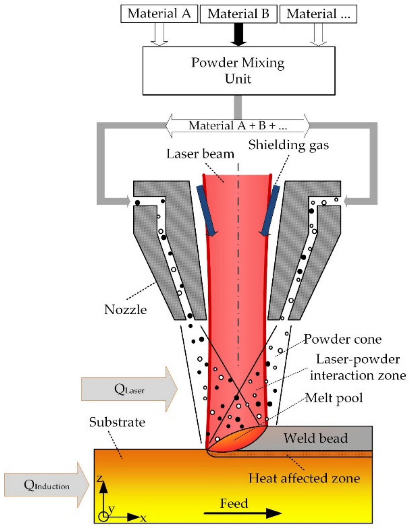
Figure 1.
Illustration of the multi-material LMD process with additional inductive substrate heating, reproduced and adapted with permission from [
10].
Figure 1.
Illustration of the multi-material LMD process with additional inductive substrate heating, reproduced and adapted with permission from [
10].
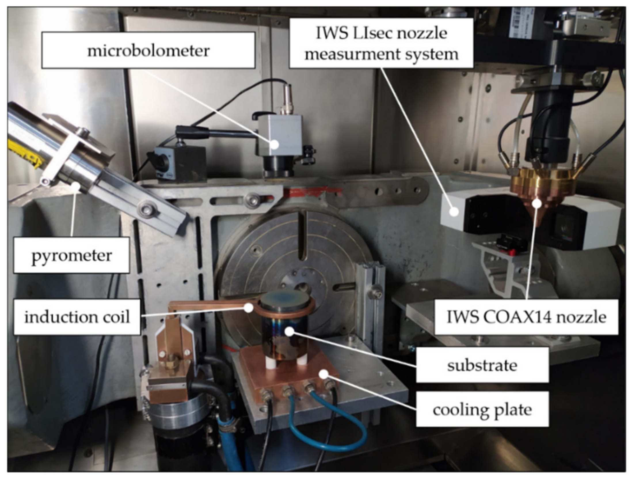
Figure 2.
Test set up for the conducted LMD trials.
Figure 2.
Test set up for the conducted LMD trials.
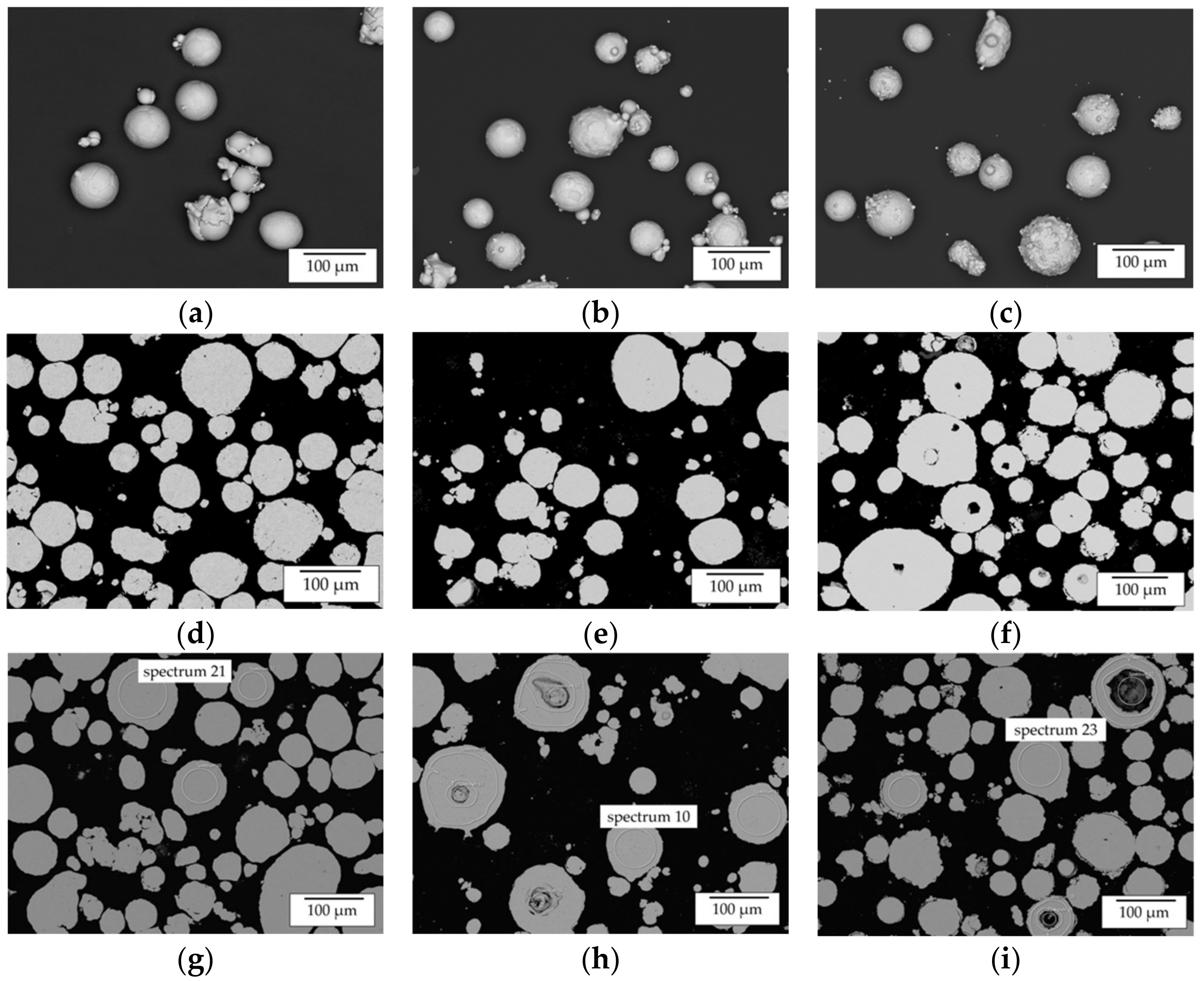
Figure 3.
Overview of SEM images of the used powder material—(a–c) SEM of loose powder particles (a—Al, b—Ni; c—NiAl); (d–f) SEM of powder particle cross sections (d—Al, e—Ni; f—NiAl); (g–i) SEM of powder particle cross sections with marked regions, which were analyzed by EDX (g—Al, h—Ni; i—NiAl).
Figure 3.
Overview of SEM images of the used powder material—(a–c) SEM of loose powder particles (a—Al, b—Ni; c—NiAl); (d–f) SEM of powder particle cross sections (d—Al, e—Ni; f—NiAl); (g–i) SEM of powder particle cross sections with marked regions, which were analyzed by EDX (g—Al, h—Ni; i—NiAl).
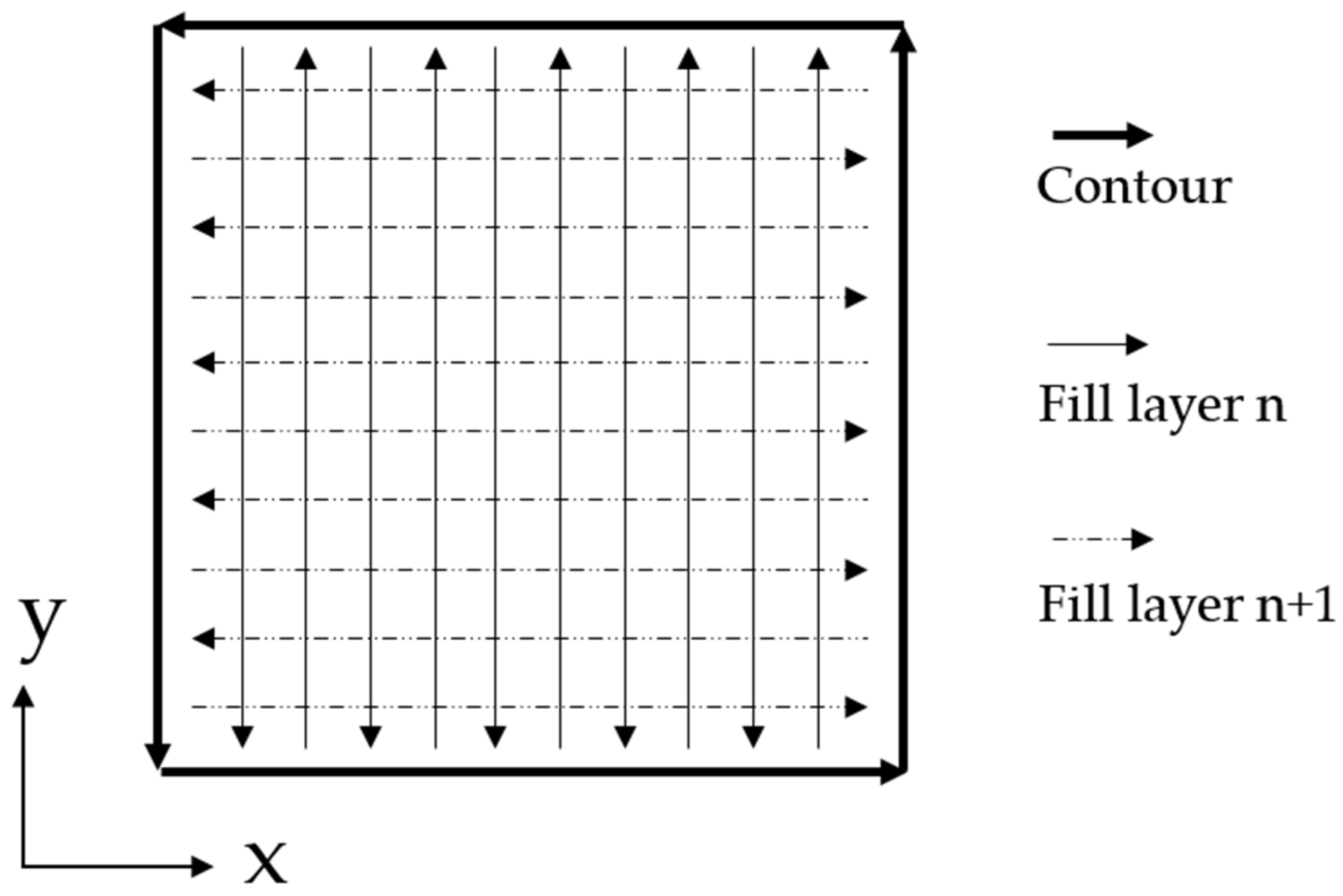
Figure 4.
Weld path pattern for single-layers and multi-layer build-ups.
Figure 4.
Weld path pattern for single-layers and multi-layer build-ups.
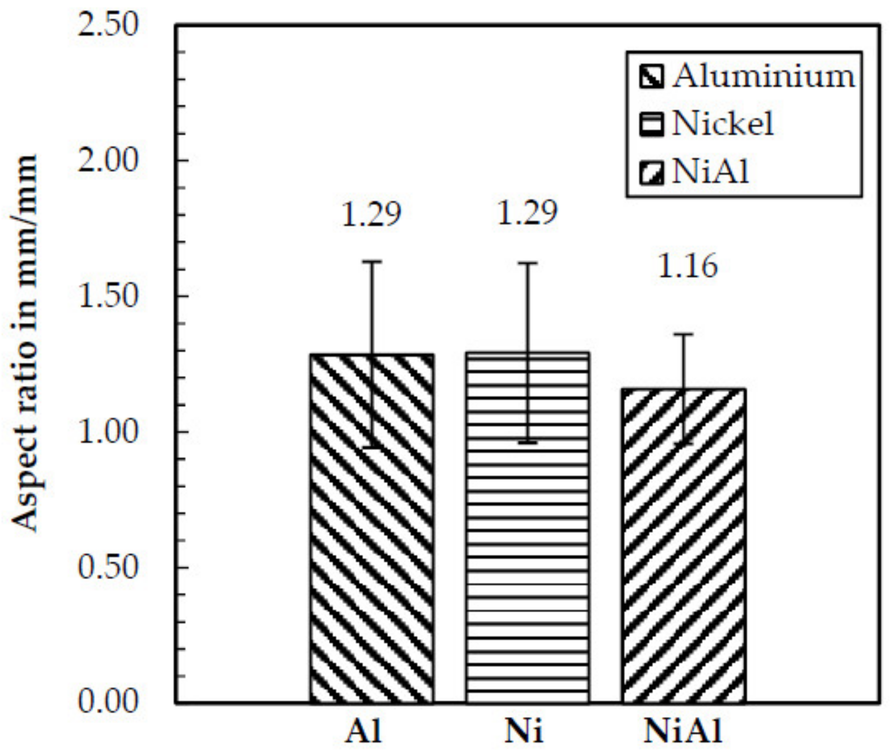
Figure 5.
Aspect ratio of the used powders determined by image analysis.
Figure 5.
Aspect ratio of the used powders determined by image analysis.
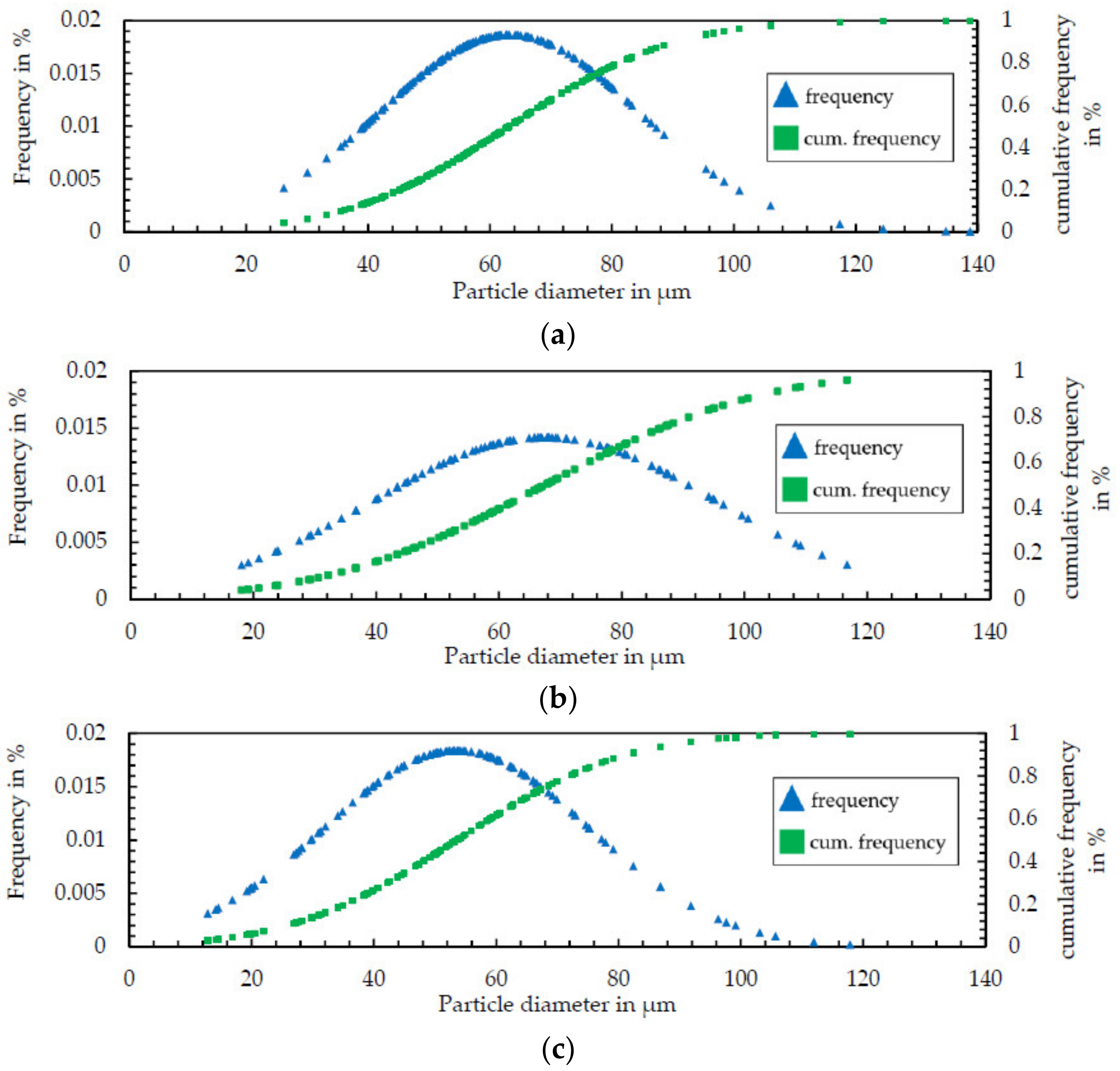
Figure 6.
Particle size distribution of the used Ni50Al50 powder (a), Al powder (b) and Ni-alloy 201 powder (c) determined by image analysis.
Figure 6.
Particle size distribution of the used Ni50Al50 powder (a), Al powder (b) and Ni-alloy 201 powder (c) determined by image analysis.
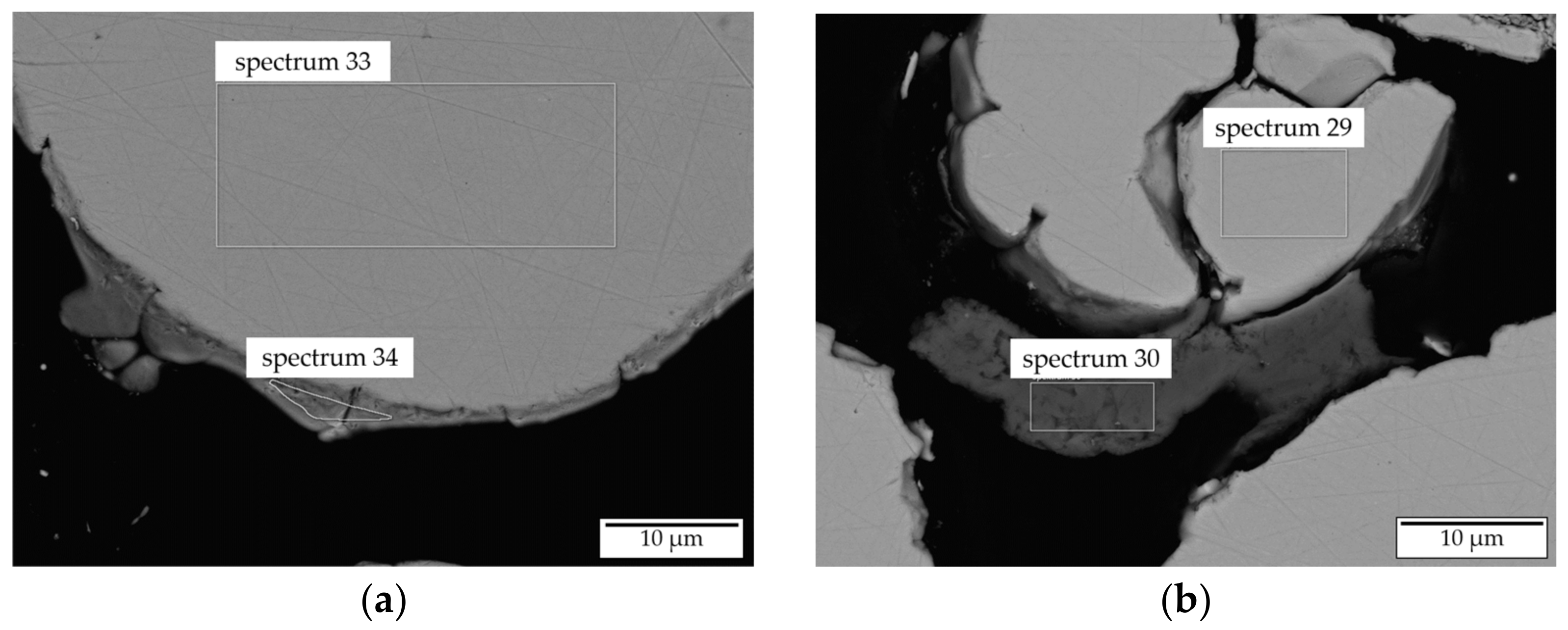
Figure 7.
SEM images of Ni50Al50 powder cross sections with the marked regions investigated by EDX ((a)—region 33 and 34; (b)—region 29 and 30).
Figure 7.
SEM images of Ni50Al50 powder cross sections with the marked regions investigated by EDX ((a)—region 33 and 34; (b)—region 29 and 30).
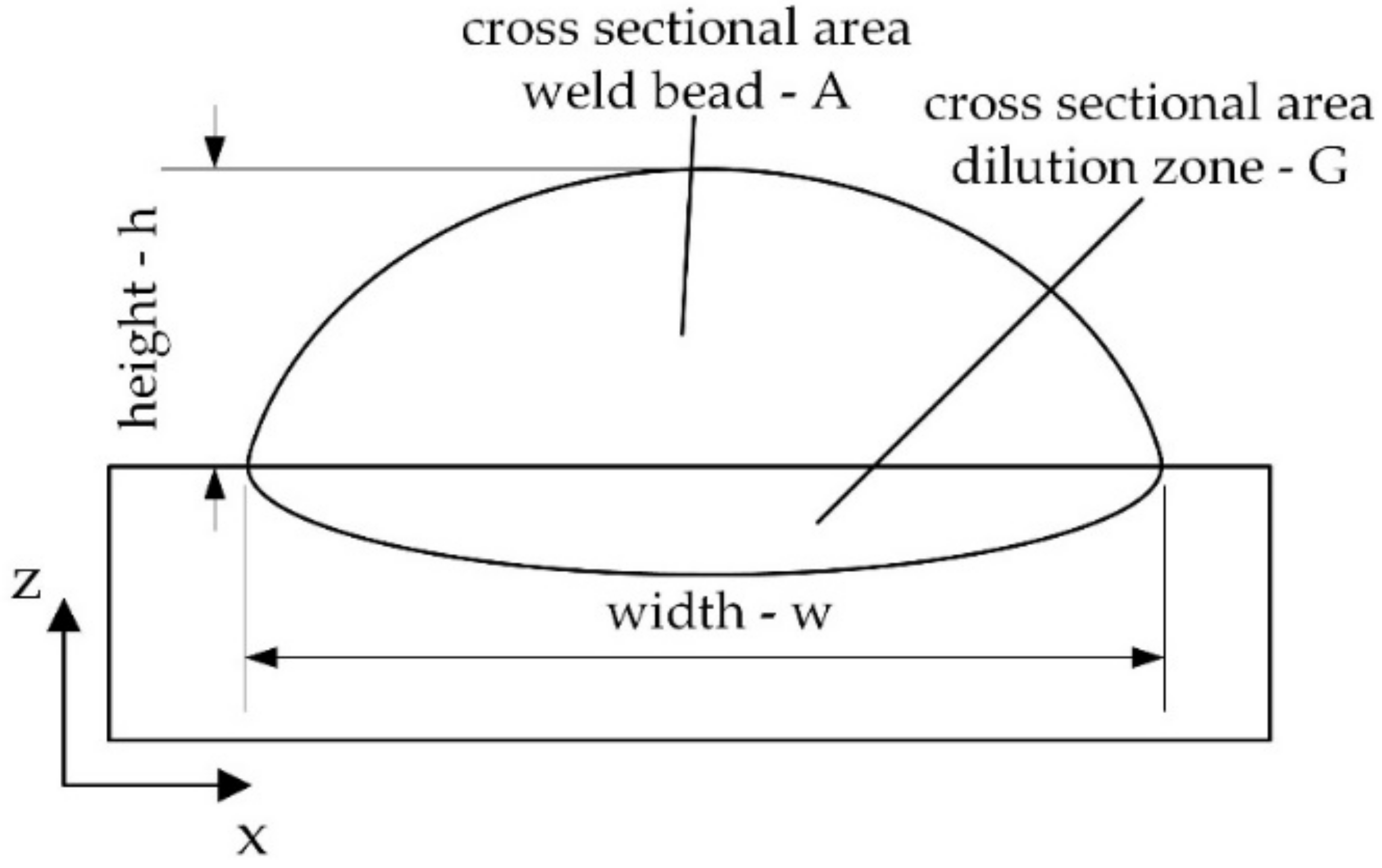
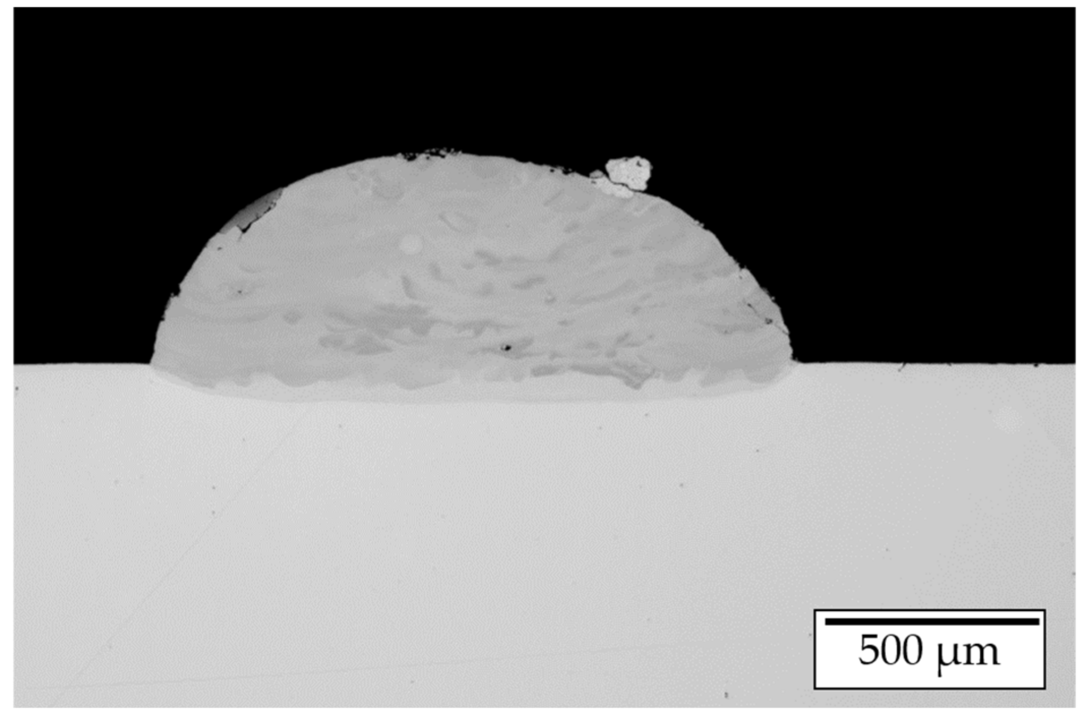
Figure 8.
Geometrical features of single LMD weld tracks.
Figure 8.
Geometrical features of single LMD weld tracks.
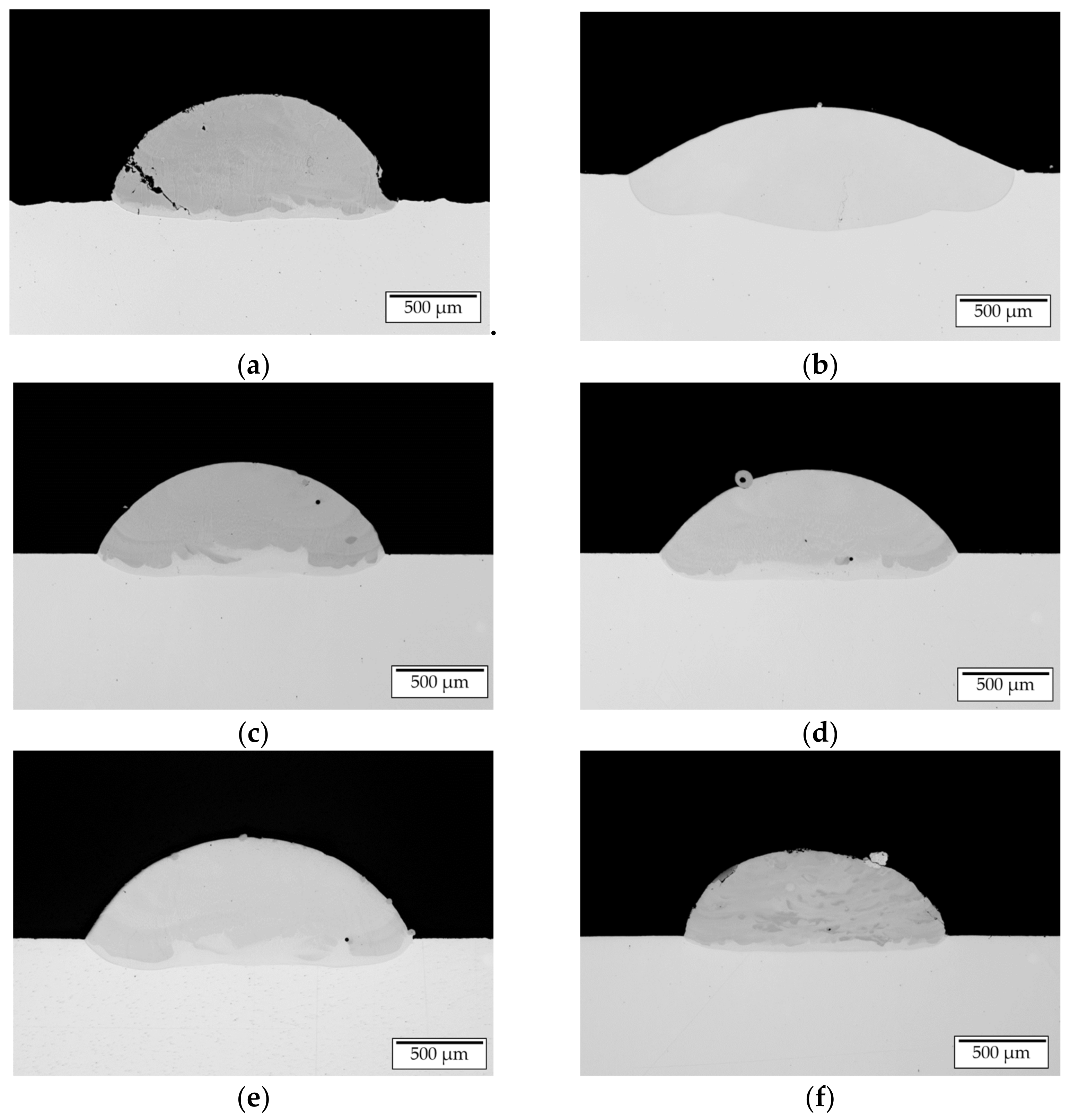
Figure 9.
LOM images of cross sections of manufactured single tracks (a)—set 1, (b)—set 2, (c)—set 3, (d)—set 4, (e)—set 5, (f)—set 6.
Figure 9.
LOM images of cross sections of manufactured single tracks (a)—set 1, (b)—set 2, (c)—set 3, (d)—set 4, (e)—set 5, (f)—set 6.
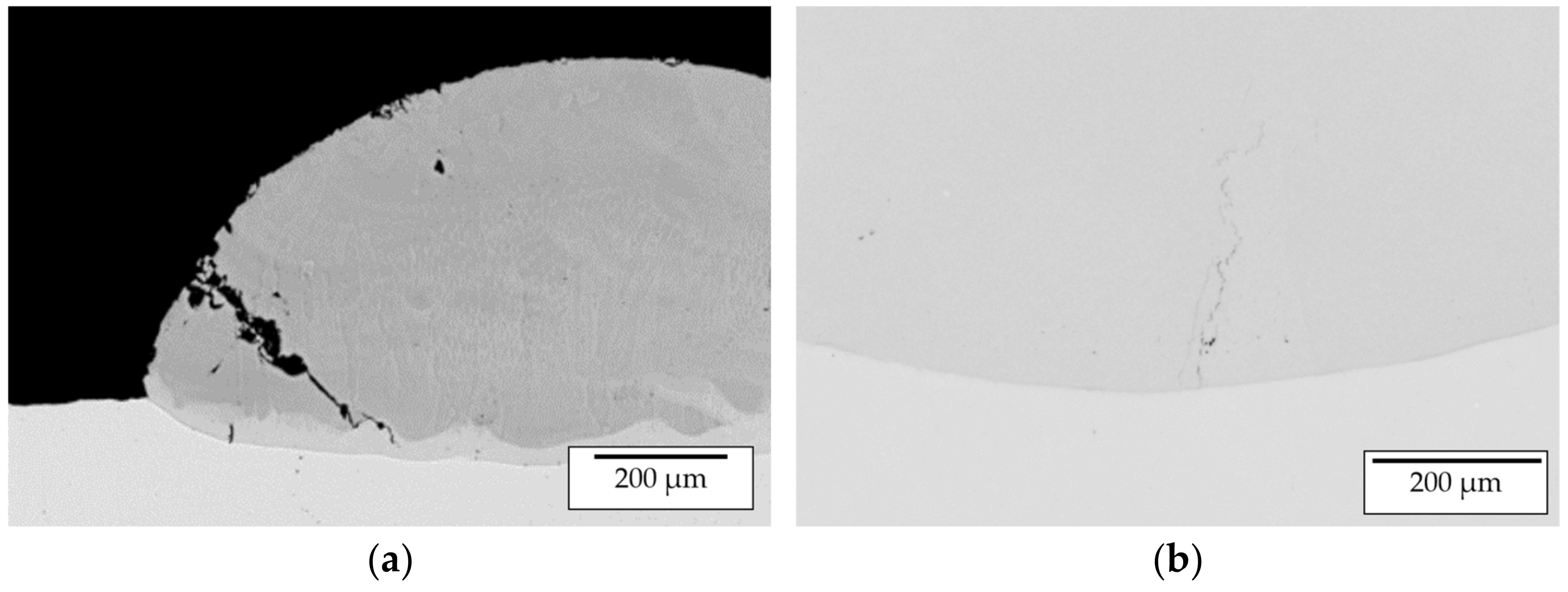
Figure 10.
(a) Cold cracking due to processing without substrate pre-heating; (b) hot crack formation within single track.
Figure 10.
(a) Cold cracking due to processing without substrate pre-heating; (b) hot crack formation within single track.
Figure 11.
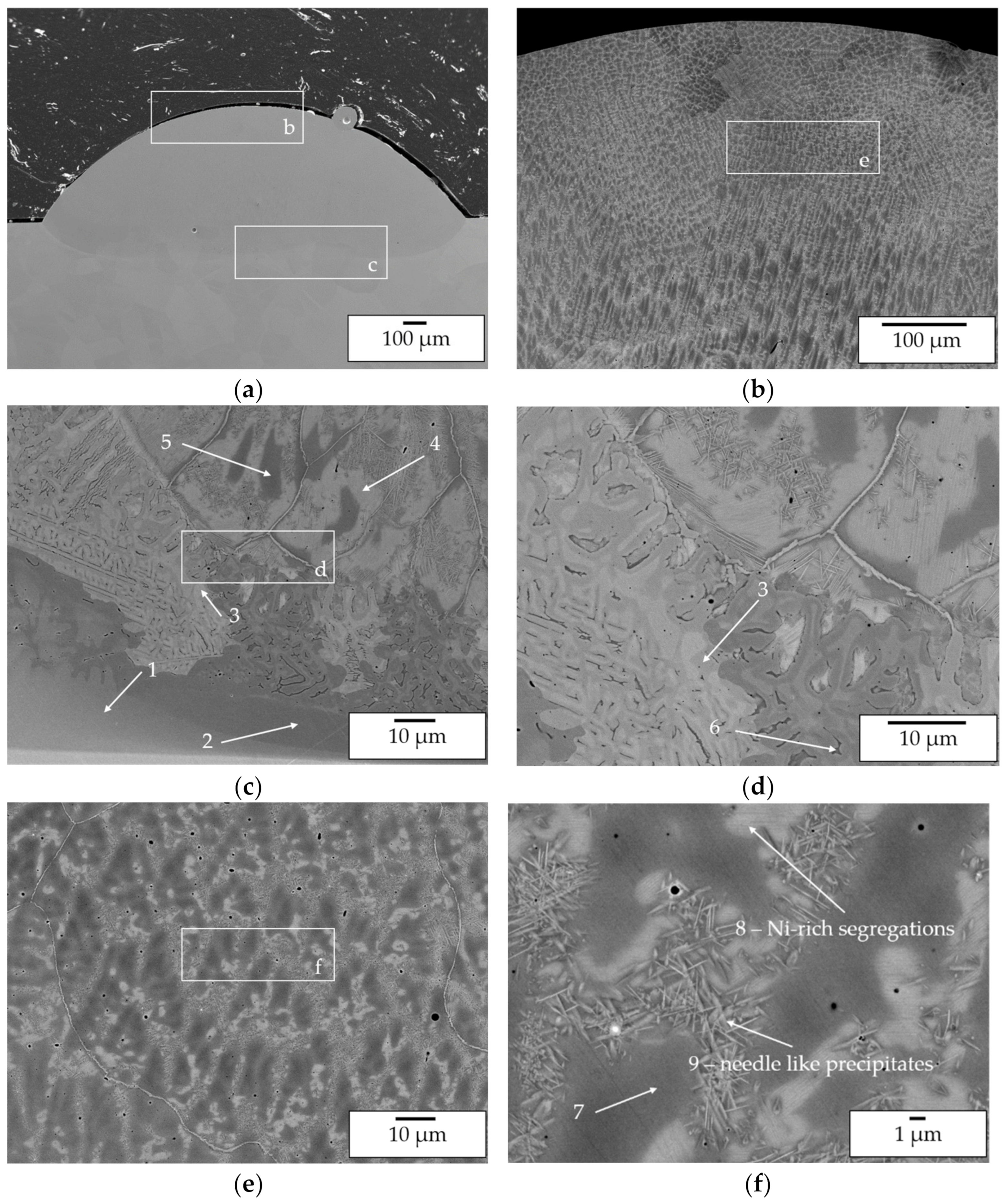
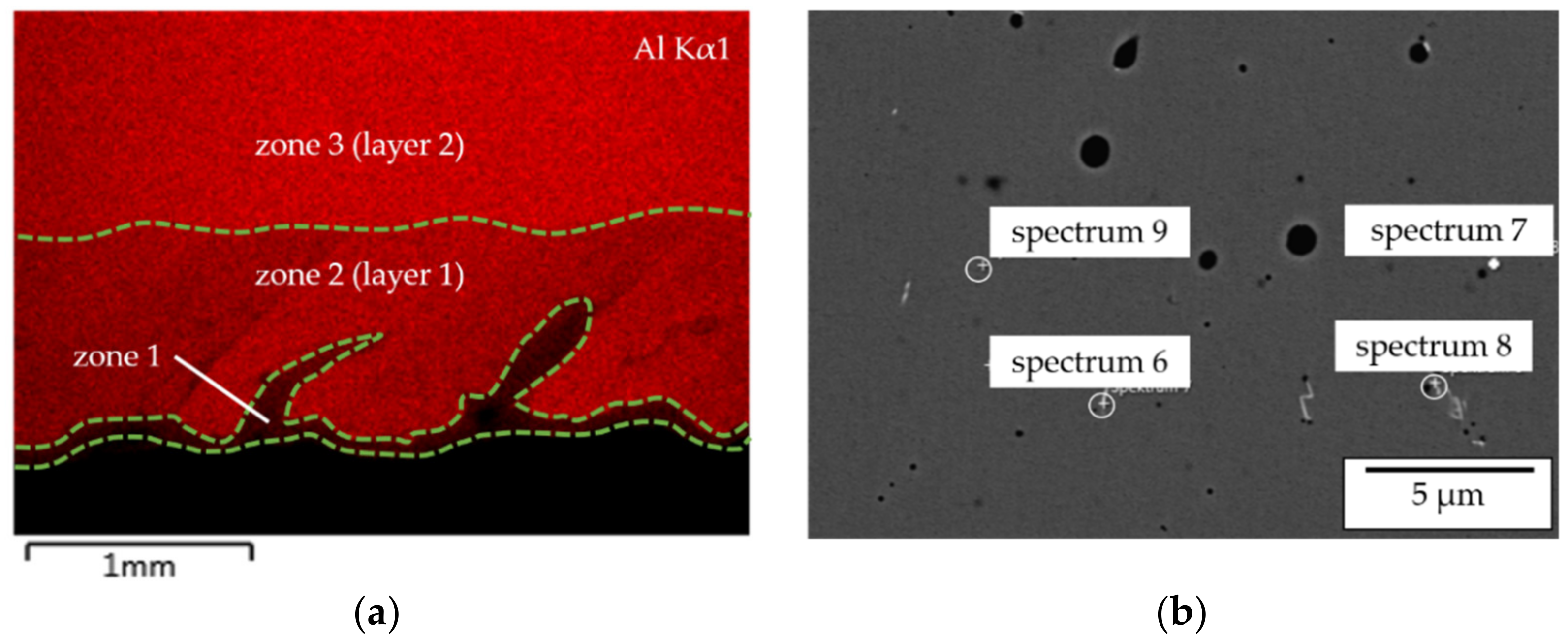
SEM images of a weld track deposited with parameter set 4; (a) overview of the weld track; (b) top region of weld track at 200× magnification; (c) transition region from substrate to weld track at 100× magnification with marked regions 1–5 investigated by EDX; (d) transition zone from substrate to weld track at 2000× magnification with marked region 3 and 6 investigated by EDX; (e) top region of weld track at 1000× magnification; (f) top region of weld track at 5000× magnification with marked regions 7–9 investigated by EDX.
Figure 11.
SEM images of a weld track deposited with parameter set 4; (a) overview of the weld track; (b) top region of weld track at 200× magnification; (c) transition region from substrate to weld track at 100× magnification with marked regions 1–5 investigated by EDX; (d) transition zone from substrate to weld track at 2000× magnification with marked region 3 and 6 investigated by EDX; (e) top region of weld track at 1000× magnification; (f) top region of weld track at 5000× magnification with marked regions 7–9 investigated by EDX.
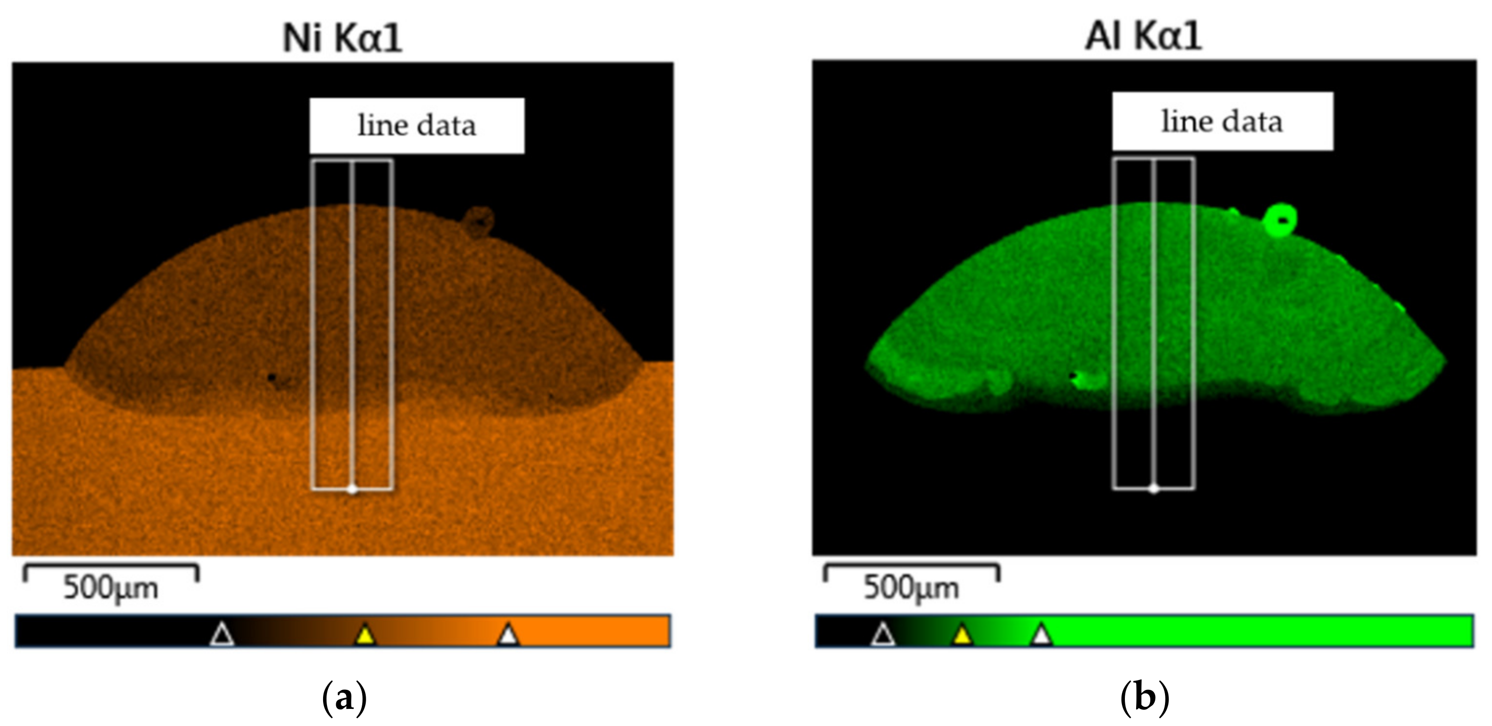
Figure 12.
EDX mapping of the Ni (a) and as well as Al (b) content within of a weld track deposited at 900 °C pre-heating temperature, 800 W laser power and 400 mm/min feeding speed.
Figure 12.
EDX mapping of the Ni (a) and as well as Al (b) content within of a weld track deposited at 900 °C pre-heating temperature, 800 W laser power and 400 mm/min feeding speed.
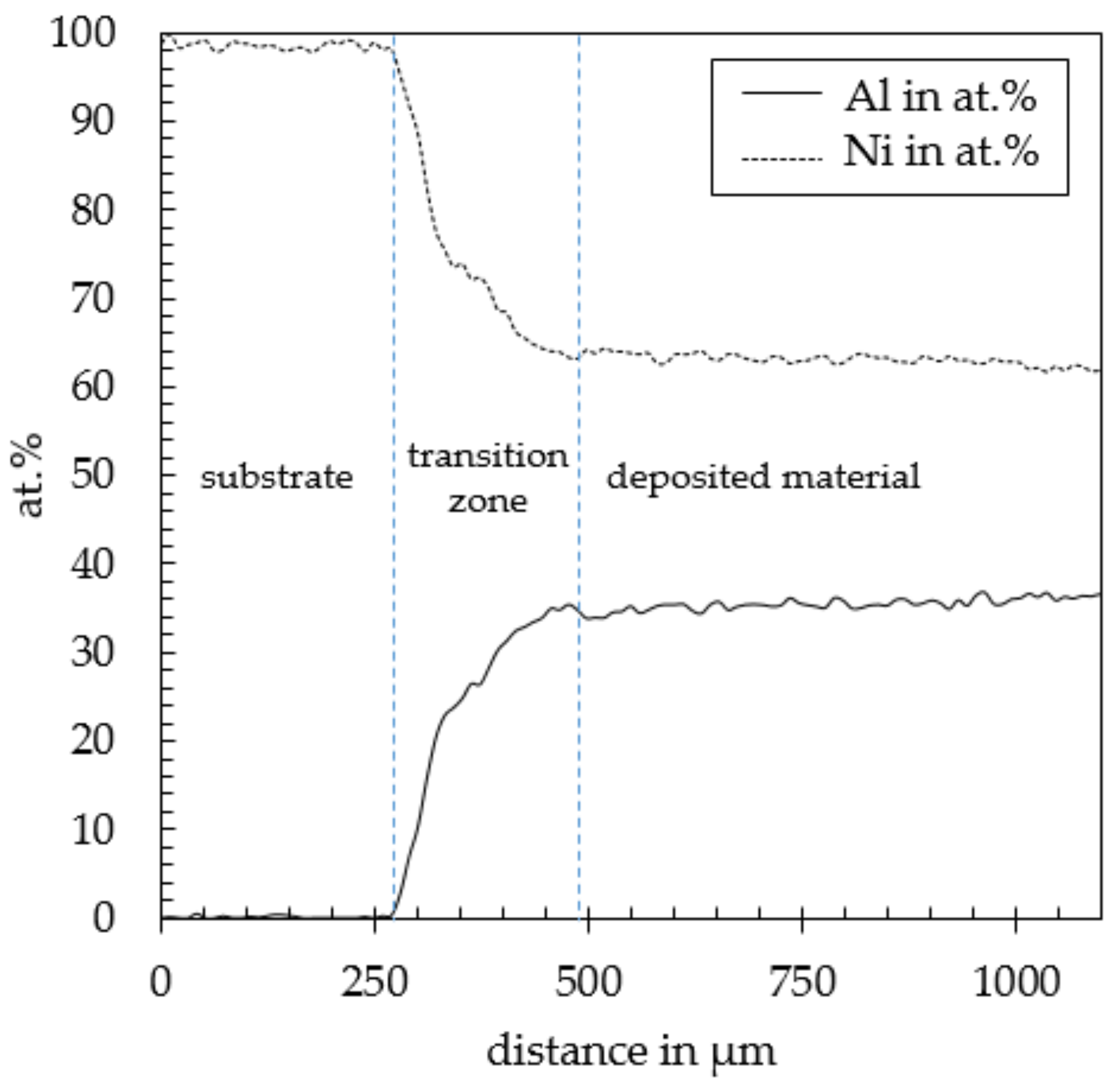
Figure 13.
EDX data along the weld track showing the high degree of dilution in weld track deposited at 900 °C pre-heating temperature, 800 W laser power and 400 mm/min feeding speed.
Figure 13.
EDX data along the weld track showing the high degree of dilution in weld track deposited at 900 °C pre-heating temperature, 800 W laser power and 400 mm/min feeding speed.
Figure 14.
LOM image of a single track manufactured by in-situ alloying of elemental Ni and Al.
Figure 14.
LOM image of a single track manufactured by in-situ alloying of elemental Ni and Al.
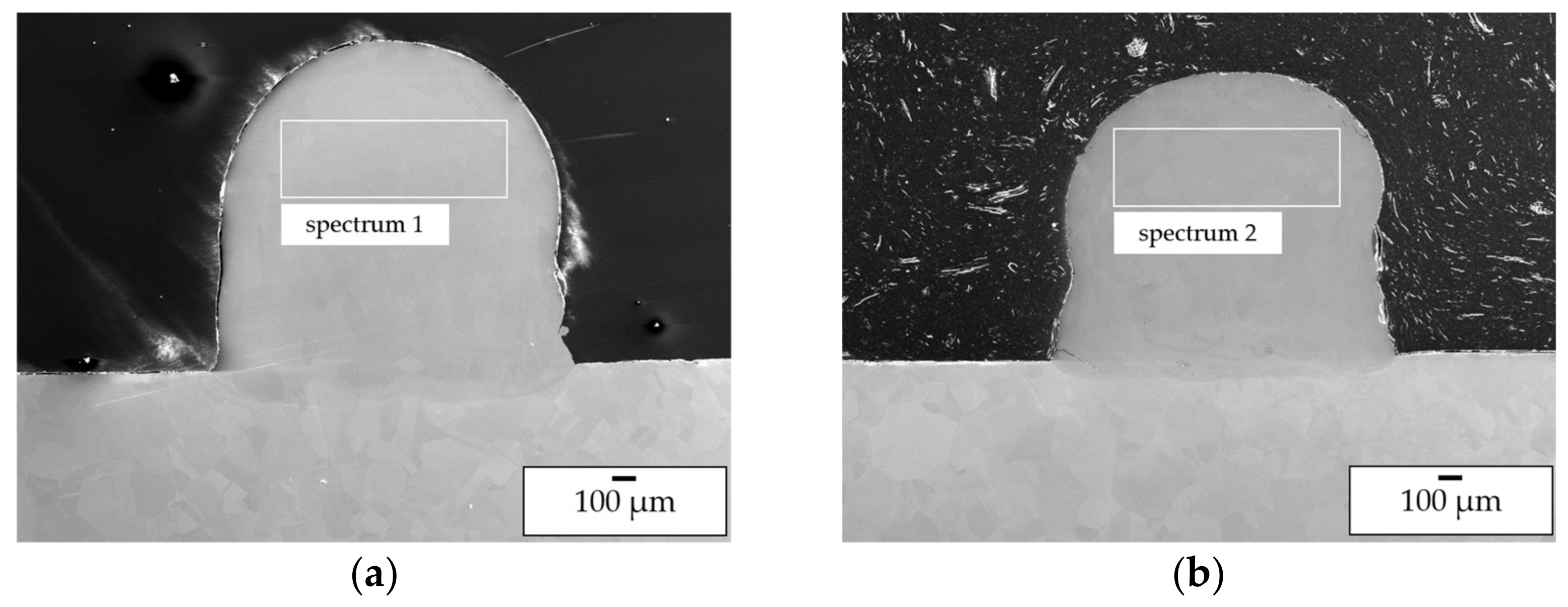
Figure 15.
SEM BSE images of wall specimens consisting of three tracks manufactured using pre-alloyed powder (a) and in situ alloying (b).
Figure 15.
SEM BSE images of wall specimens consisting of three tracks manufactured using pre-alloyed powder (a) and in situ alloying (b).
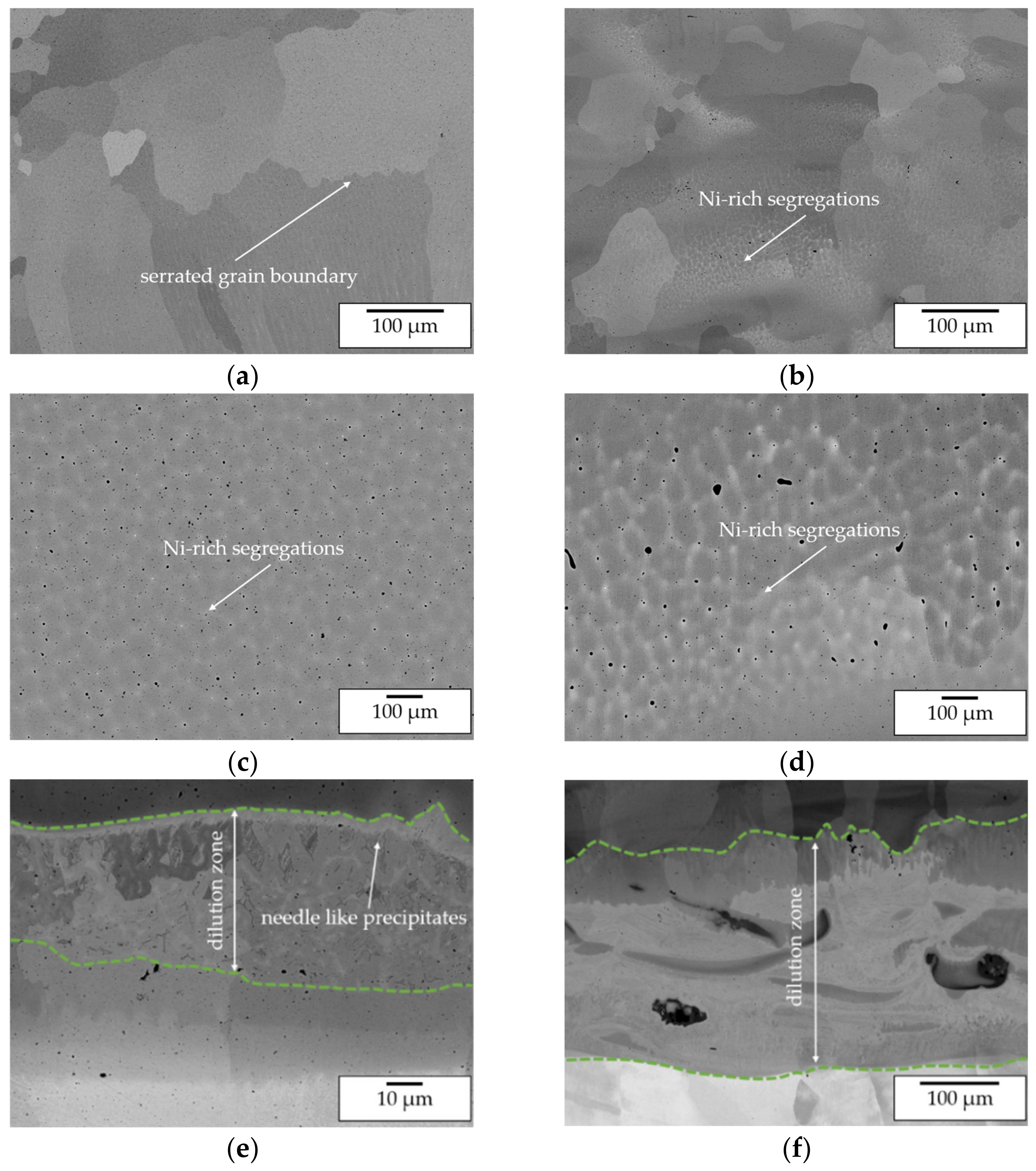
Figure 16.
SEM images of manufactured wall specimens—(a) top layer, pre-alloyed powder processing; (b) top layer, in situ alloying; (c) Ni-rich segregations, pre-alloyed powder processing; (d) Ni-rich segregations, in situ alloying; (e) transition zone, pre-alloyed powder processing; (f) transition zone, in situ alloying.
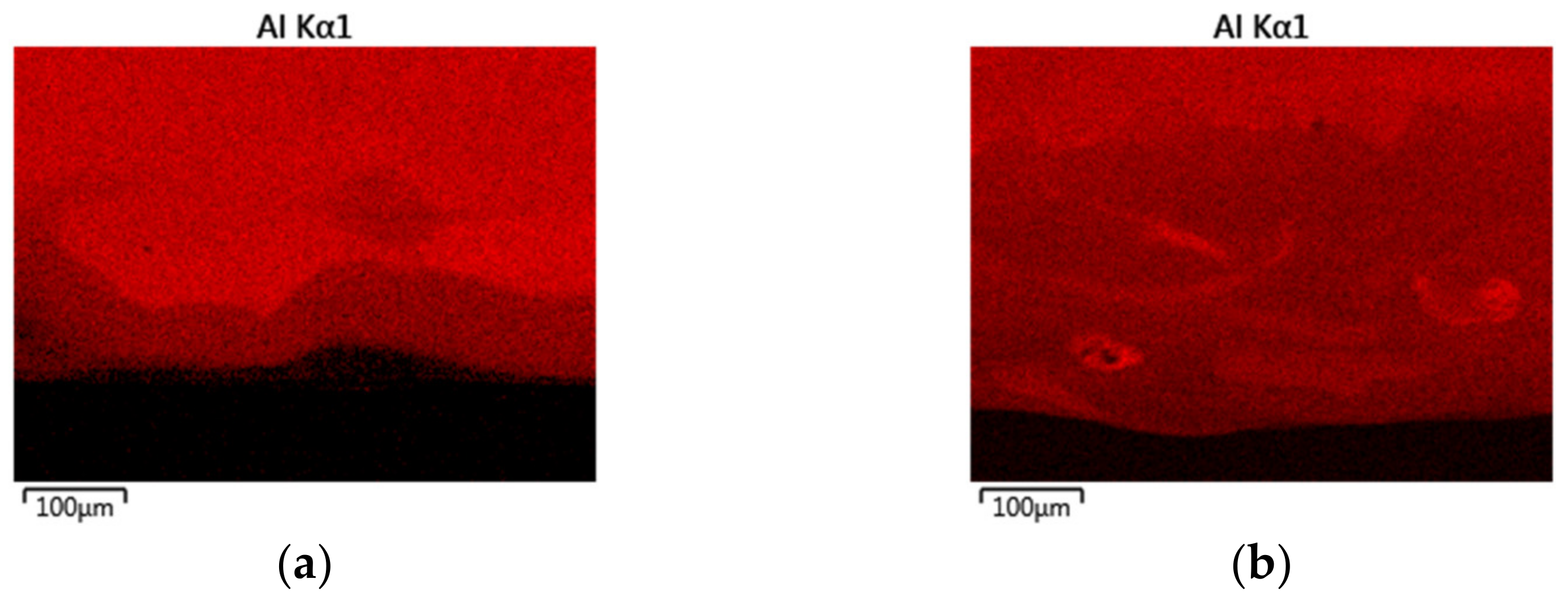
Figure 17.
EDX mapping of the Al distribution within the transition zone showing the differences in intermixing between the processing of pre-alloyed (a) and elemental (b) powders.
Figure 17.
EDX mapping of the Al distribution within the transition zone showing the differences in intermixing between the processing of pre-alloyed (a) and elemental (b) powders.
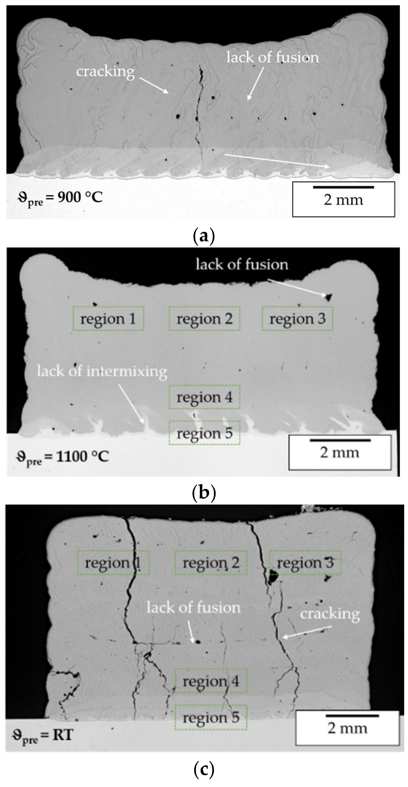
Figure 18.
LOM images of cuboid specimens manufactured using pre-alloyed powder ((a) preheating temperature 900 °C; (b) preheating temperature 1100 °C) and in situ alloying ((c) no preheating), marked regions indicate areas analyzed by XRD.
Figure 18.
LOM images of cuboid specimens manufactured using pre-alloyed powder ((a) preheating temperature 900 °C; (b) preheating temperature 1100 °C) and in situ alloying ((c) no preheating), marked regions indicate areas analyzed by XRD.
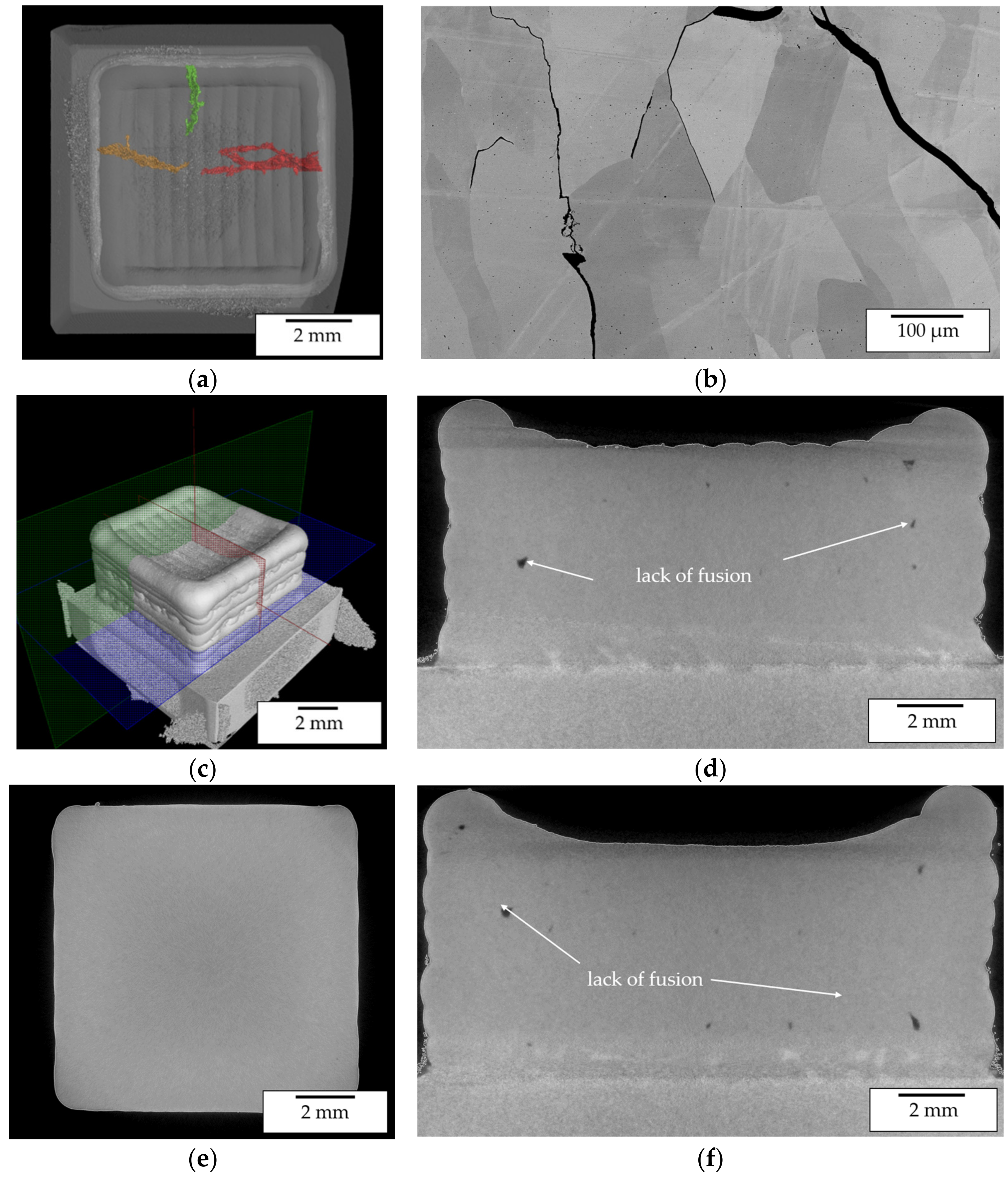
Figure 19.
(a) CT image exhibiting crack formation perpendicular to the alternating welding direction in a cuboid specimen manufactured at 900 °C preheating temperature using pre-alloyed powder; (b) SEM image of crack propagation within cuboid specimen; (c) CT iso-view image of cuboid specimen; (d) CT image of cross section in zx-plane; (e) CT image of cross section in xy-plane; (f) CT image of cross section in zy-plan.
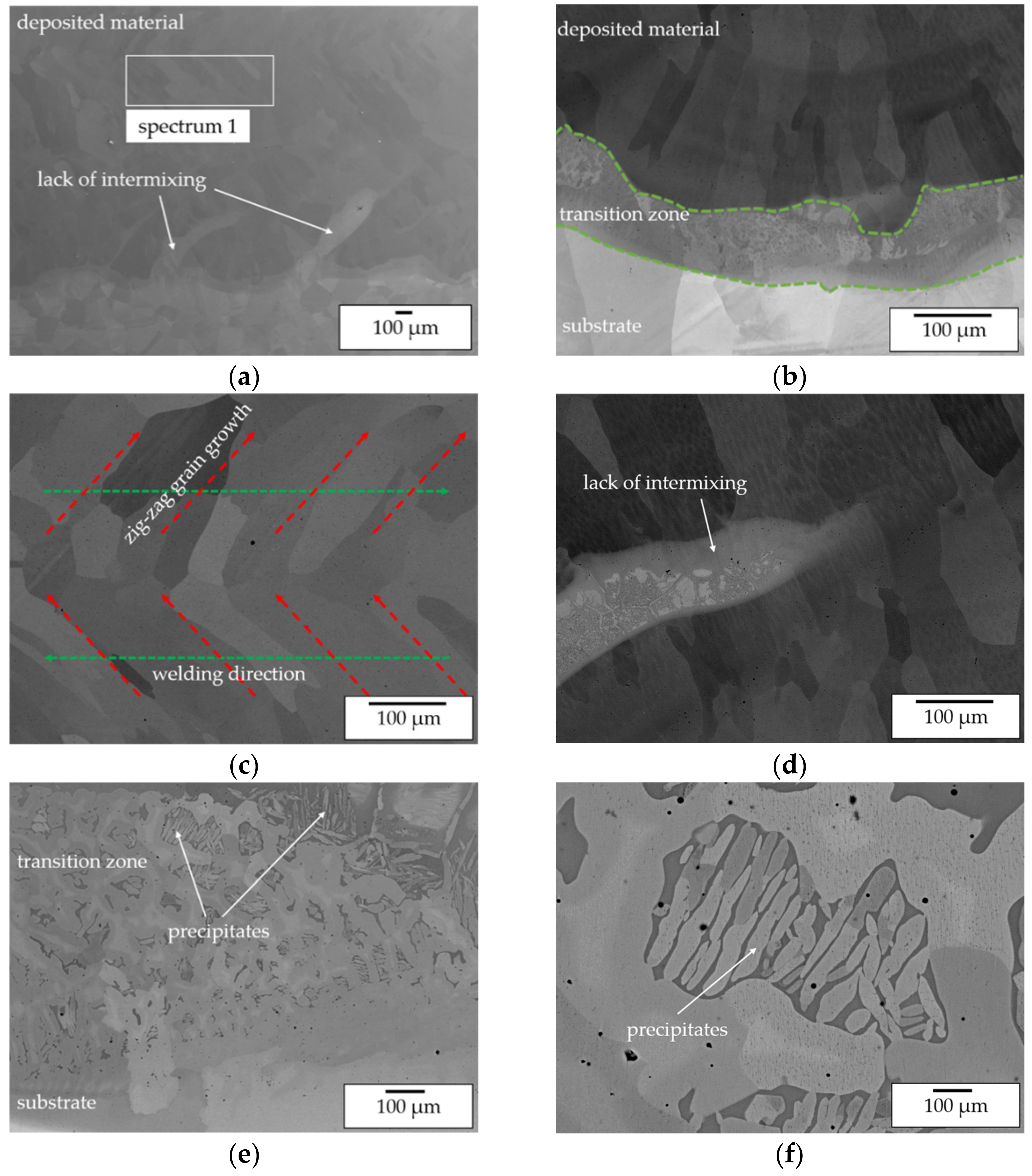
Figure 20.
SEM BEC images of a cuboid specimen manufactured with pre-alloyed powder at 1100 °C pre-heating temperature—(a) overview showing transition from Ni substrate to the deposited single phase β-NiAl material; (b) Ni-NiAl transition zone at 200× magnification; (c) zig-zag grain structure of the deposited single phase β-NiAl material; (d) lack of intermixing causing multi-phase Ni-rich regions; (e) transition zone at 1000× magnification; (f) transition zone at 500× magnification showing the formation of precipitates.
Figure 21.
(a) EDX mapping of the Al distribution within the transition zone; (b) EDX analysis of Zr-rich precipitates within the deposited material.
Figure 21.
(a) EDX mapping of the Al distribution within the transition zone; (b) EDX analysis of Zr-rich precipitates within the deposited material.
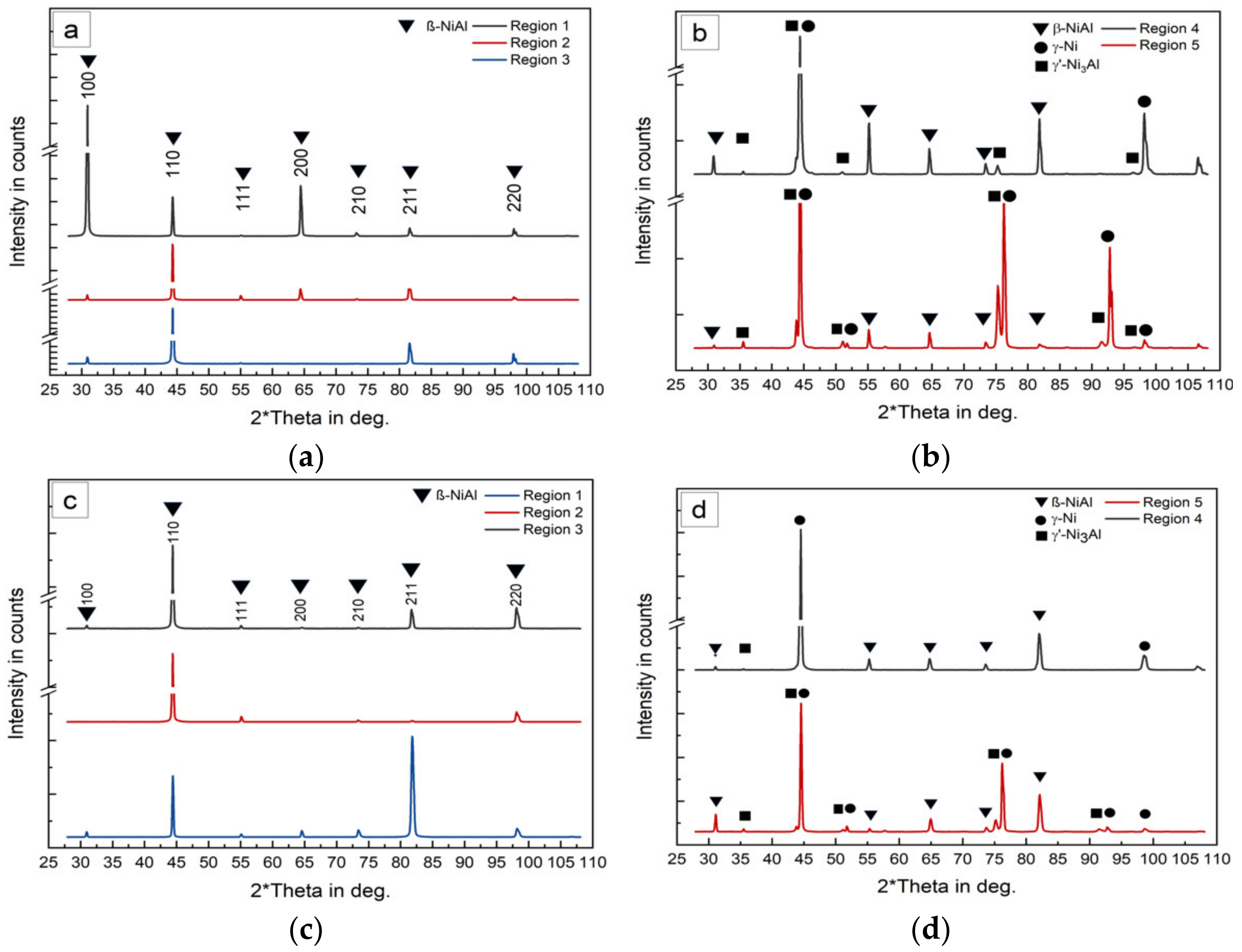
Figure 22.
XRD patterns in different regions of a cuboid specimen manufactured using pre-alloyed powder (
a,
b) and in situ alloying (
c,
d), reference in
Figure 14.
Figure 22.
XRD patterns in different regions of a cuboid specimen manufactured using pre-alloyed powder (
a,
b) and in situ alloying (
c,
d), reference in
Figure 14.
Table 1.
Comparison of state-of-the art nickel-based superalloy IN 718 and β-NiAl [
3,
4].
Table 1.
Comparison of state-of-the art nickel-based superalloy IN 718 and β-NiAl [
3,
4].
| Properties | β-NiAl | IN 718 |
|---|
| density (g·cm−3) | 5.9 | 8.2 |
| therm. conductivity (W·m−1·K−1) | 76.0 | 11.4 |
| melting range (°C) | 1638 | 1260–1336 |
| ϑmax creep resistance (°C) | 1100 | 700 |
| ϑmax oxidation resistance (°C) | 1400 | 1000 |
Table 2.
Equipment used for the presented experimental investigations.
Table 2.
Equipment used for the presented experimental investigations.
| Equipment | Type |
|---|
| Laser source | Laserline LDF 1500–400, Germany |
| Deposition system | Fraunhofer IWS COAX 14, Germany |
| Powder feeder | GTV PF 2/2, Luckenbach, Germany |
| Induction system | EMAG eldec MICO 50/80, Dornstetten,
Germany |
| IR-Camera | Optris PI 640, Berlin, Germany |
| Pyrometer | Advanced Energy Impac IGA 6/23, Frankfurt, Germany |
| Light Optical Microscope (LOM) | Olympus GX51, Japan |
| Scanning Electron Microscopy (SEM) | Jeol JSM 6610, Japan |
| Energy-dispersive X-ray spectroscopy (EDX) | Oxford instruments X-MAX, Abingdon, UK |
Table 3.
Chemical composition of the powder and substrate material.
Table 3.
Chemical composition of the powder and substrate material.
| Alloy | Ni (at.%) | Al (at.%) | Fe (at.%) | Si (at.%) | Mn (at.%) |
|---|
| Ni | 99.92 | 0.00 | 0.042 | 0.032 | 0.003 |
| Al | 0.00 | 99.9 | 0.019 | 0.015 | 0.001 |
| Ni50Al50 | 52.86 | 47.0 | 0.031 | 0.024 | 0.002 |
| Alloy 201 | 99.82 | 0.00 | 0.042 | 0.032 | 0.099 |
Table 4.
Overview of the process parameters and pre-heating temperature for the analyzed single tracks made of pre-alloyed powder. (RT—room temperature).
Table 4.
Overview of the process parameters and pre-heating temperature for the analyzed single tracks made of pre-alloyed powder. (RT—room temperature).
| Set | Laser Power (W) | Feeding Speed (mm/min) | Temperature (°C) |
|---|
| 1 | 1500 | 400 | RT |
| 2 | 1500 | 400 | 700 |
| 3 | 800 | 400 | 700 |
| 4 | 800 | 400 | 900 |
| 5 | 800 | 400 | 1100 |
| 6 | 1250 | 400 | RT |
Table 5.
Elemental composition of selected powder particles.
Table 5.
Elemental composition of selected powder particles.
| Spectrum | Ni (at.%) | Al (at.%) | Si (at.%) |
|---|
| 10 | 98.3 | - | - |
| 21 | - | 98.5 | - |
| 23 | 50.8 | 49.2 | - |
| 29 | 51.6 | 48.4 | - |
| 30 | 1.0 | 94.31 | - |
| 33 | 51 | 49 | - |
| 34 | 94.6 | 1.4 | 0.3 |
Table 6.
Geometrical features of the deposited tracks for the selected sets of parameters.
Table 6.
Geometrical features of the deposited tracks for the selected sets of parameters.
| Set | (mm)
| (mm)
| | | | |
|---|
| 1 | 1.74 | 0.58 | 0.73 | 0.16 | 0.33 | 0.18 |
| 2 | 2.34 | 0.39 | 0.57 | 0.63 | 0.17 | 0.53 |
| 3 | 1.62 | 0.52 | 0.63 | 0.17 | 0.32 | 0.21 |
| 4 | 1.67 | 0.56 | 0.69 | 0.19 | 0.34 | 0.22 |
| 5 | 1.8 | 0.52 | 0.65 | 0.27 | 0.29 | 0.29 |
| 6 | 1.66 | 0.52 | 0.67 | 0.16 | 0.31 | 0.19 |
Table 7.
Regions analyzed by EDX within a single track manufactured at 900 °C pre-heating temperature, 800 W laser power and 400 mm/min feeding speed, reference
Figure 11.
Table 7.
Regions analyzed by EDX within a single track manufactured at 900 °C pre-heating temperature, 800 W laser power and 400 mm/min feeding speed, reference
Figure 11.
| Region | Spectrum | Ni (at.%) | Al (at.%) |
|---|
| Transition zone | 1 | 82.9 | 17.1 |
| 2 | 75.8 | 24.2 |
| 3 | 78.4 | 21.6 |
| 4 | 64.3 | 35.7 |
| 5 | 63.4 | 36.6 |
| 6 | 64.0 | 36.0 |
| Top zone | 7 | 62.5 | 37.5 |
| 8 | 64.1 | 35.9 |
| 9 | 65.7 | 34.3 |
Table 8.
Chemical composition of the analyzed region marked in
Figure 21.
Table 8.
Chemical composition of the analyzed region marked in
Figure 21.
| Spectrum | Ni (at.%) | Al (at.%) | Zr (at.%) |
|---|
| 6 | 49.9 | 32.9 | 17.2 |
| 7 | 50.1 | 36.4 | 13.4 |
| 8 | 48.9 | 43.4 | 16.7 |


