Article

Improvement of the Machining Performance of the TW-ECDM Process Using Magnetohydrodynamics (MHD) on Quartz Material

1
Industrial Engineering Department, Pandit Deendayal Energy University, Gandhinagar 382007, India
2
Mechanical Engineering Department, Pandit Deendayal Energy University, Gandhinagar 382007, India
3
Materials Engineering, Indian Institute of Technology, Gandhinagar-382355, India
4
Production & Industrial Engineering Department, Punjab Engineering College, Chandigarh 160012, India
5
Mechanical Engineering, Imperial College London, Exhibition Rd., London SW7 2AZ, UK
6
Design, Manufacturing & Engineering Management, University of Strathclyde, Glasgow G1 1XJ, UK
7
Savaria Institute of Technology, ELTE Eötvös Loránd University, 9700 Szombathely, Hungary
*
Authors to whom correspondence should be addressed.
Submission received: 23 March 2021 / Revised: 27 April 2021 / Accepted: 29 April 2021 / Published: 3 May 2021
(This article belongs to the Special Issue Machinability of Metallic Materials and Composites)

Abstract

:
Many microslits are typically manufactured on quartz substrates and are used to improve their industrial performance. The fabrication of microslits on quartz is difficult and expensive to achieve using recent traditional machining processes due to its hardness, electrically insulating nature, and brittleness. The key objective of the current study was to demonstrate the fabrication of microslits on quartz material through a magnetohydrodynamics (MHD)-assisted traveling wire-electrochemical discharge micromachining process. Hydrogen gas bubbles were concentrated around the entire wire surface during electrolysis. This led to a less active dynamic region of the wire electrode, which decreased the adequacy of the electrolysis process and the machining effectiveness. The test results affirmed that the MHD convection approach evacuated the gas bubbles more rapidly and improved the void fraction in the gas bubble scattering layer. Furthermore, the improvements in the material removal rate and length of the cut were 85.28% and 48.86%, respectively, and the surface roughness was reduced by 30.39% using the MHD approach. A crossover methodology with a Taguchi design and ANOVA was utilized to study the machining performance. This exploratory investigation gives an unused strategy that shows a few advantages over the traditional TW-ECDM process.

1. Introduction

In recent times, the usage of miniature products and their applications has significantly increased. This has led to an increase in the demand to create complex geometries with precise dimensions and high quality. These devices are comprehensively studied, which allows for constructive applications for chemical and biological investigation [1]. Generally, microchannels/slits are made of glass and polymer materials [2]. The microchannel chips that are made from polymeric materials have many limitations, viz. low solidity after exposure to a heated atmosphere, meager chemical resistance and optical properties, and low porousness to moisture [3,4]. Therefore, quantifiable fabrication methods have been examined for quartz-glass-based microchannels [5]. The patterns created in glass and ceramics are difficult to create due to the brittleness of quartz glass. This led to glass and ceramics being replaced by polydimethylsiloxane (PDMS) in many applications [6]. Quartz glass may be an immaculate shape of silica with a SiO2 content of more than 99.9% and it has been used widely in lenses, computers, resonators, windows, smartphones, GPS equipment, communication (3C) engineering, and electronic industries for high-quality tuned circuits. Quartz is widely used in micro device testing, metrology components, jewelry, gemstones, frequency control, mirror substrates, piezoelectric applications for converting electrical to mechanical energy (and vice versa), and medical incision devices [6,7,8,9]. Owing to its higher hardness, brittleness, and higher melting point, machining quartz is difficult [10] and thus quartz was used as the workpiece material for the study.
The literature reveals that microslits on quartz material can be fabricated using various unconventional machining processes. Overcut and rough surfaces were observed with ultrashort laser pulse processes [11]. When using a Nd:YAG laser, damage and thermal cracks on the the inner machine surface were observed [12,13]. When an abrasive slurry jet was applied to machine the quartz, a large wavy pattern was observed and the material removal rate decreased [14]. Microedge cracks and burrs were noticed when a laser-assisted dry microgrinding process was applied [15]. Burrs can be reduced using laser-assisted dry microgrinding machining processes but the heat affected zone (HAZ) across the surface is a challenge [16]. When powder-mixed rotary ultrasonic motion was applied to quartz, the material removal rate increased but the chances of crack propagation limits its use [17]. Rounded cracks were formed and the machined surface melted when using the electrochemical spark trepanning process [18]. A high aspect ratio was obtained using the ultra-short laser-machining processes; however, the surface roughness and surface quality were poor [19]. Furthermore, these processes had a high setup and machining cost. Other developed and broadly acknowledged machining processes, such as electrochemical machining (ECM) and wire electrical discharge machining (W-EDM), are only able to machine electrically conducting materials [20,21,22]. To overcome the previously stated key impediments, there emerges a need to create an advanced hybrid machining process that can machine different electrically nonconducting materials and make strides in the quality and nature of the machining performance [23,24].
TW-ECDM is an eminent micromachining approach with enormous potential for machining (slicing/cutting) two-dimensional and complicated profiles of a wide variety of hard, thermal-shock-resistant, indispensable, brittle, and electrically insulating materials, such as glass, zirconia, alumina, and composites. It is also known as the traveling wire electrochemical spark machining (TW-ECSM) process. A TW-ECDM process is a hybrid approach of the ECM and W-EDM processes that offers a 5 to 50 times higher material removal rate than W-EDM and ECM, and it diminishes the tool wear rate [25]. The TW-ECDM process is steadier than W-EDM and gives a better surface finish when contrasted with ECM. In the TW-ECDM process, both the electric discharge erosion and electrochemical dissolution (ESD) impacts are utilized for the evacuation of the material [26]. This helps to machine the workpiece and electrochemical dissolution gives a better and smoother surface finish. 
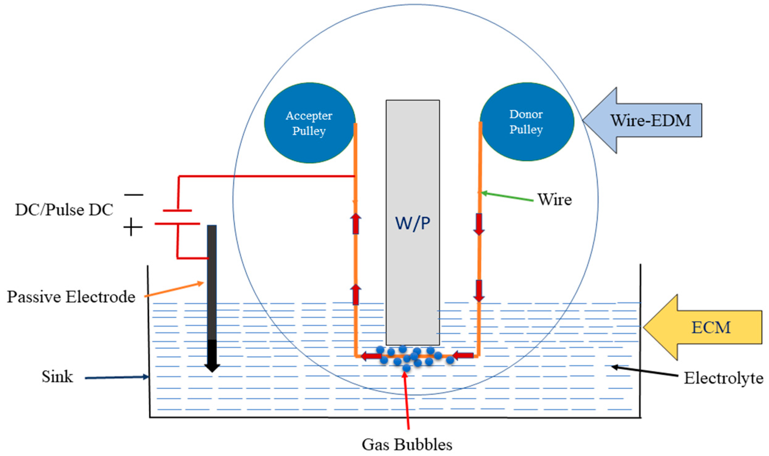
Figure 1 schematically demonstrates the TW-ECDM process. In this procedure, two terminals (electrodes) are utilized, which are plunged into the electrolyte. The electrolyte could be either alkaline or acidic. A traveling (circulating) wire is used as a cathode, which is used to cut or slice the workpiece and the auxiliary (assistant or passive) cathode is utilized as an anode. A circulating wire is kept away (0.1–0.5 mm) from the workpiece and the passive electrode is kept around 30–80 mm away from the machining zone to preserve the current density. With an increase in DC power, electrolysis is observed, and further increasing the voltage results in gas bubble generation, which is responsible for generating the spark [27]. It was observed that gas bubble formation increases with the applied voltage that was responsible for generating the spark. By further increasing the voltage, the bubbles begin to break down and provide a steady gas film around the wire. If the potential difference is high enough for a given pair of electrodes, sparking is observed, where this spark causes a streamline of high-energy electrons that are transferred with exceptionally high speed toward the workpiece. This burst of electrons produces compressive shock waves on the surface of the workpiece, which results in removing the material via melting, vaporization, and thermal erosion [28,29,30].
Many researchers have studied various aspects of the TW-ECDM process. Table 1 represents the various wires (tool electrodes) and their sizes, workpiece materials, and key findings regarding the TW-ECDM process till now. The use of a pulse DC supply reduced the surface roughness as compared to simple DC, and therefore, pulse a DC supply was selected for the present study [31]. The machining performance was improved by keeping a minimum distance between the wire and the workpiece [32]. Thermal cracks, the HAZ, and a high kerf width were found for a higher voltage, which reduced the precision and quality of machined slits, and therefore, it needs to be minimized. The electric field through the tool electrode (wire) and electrolyte was found to be responsible for producing the spark. A titrated flow for the electrolyte in the TW-ECDM process was proposed to improve the gas film formation, quality of the machined slits, and reduce the waste of the electrolyte [33]. It flushed the burrs from the cutting area and produced a stable gas film; as a result, a long and straight slit with a minimum kerf width was observed. The use of controlled electrolyte flow enhanced the machining efficiency and quality at a lesser cost. The addition of SiC particles with the titrated electrolytic flow was explored and, as a result, the surface texture improved by 80% and the mean slit breadth reduced from 200 to 185 μm [34].
The combined effects of the sparking mechanism, electrolysis, and abrasive cutting on the surface roughness, slit expansion, and MRR were reported. It was noticed that the reciprocating mechanism in TW-ECDM helped to machine the irregular cross-section [36]. Furthermore, by adding abrasive particles into the electrolyte, the slit expansion was reduced because the abrasive particles disturbed the accumulated gas bubbles that formed an isolating film around the wire. To minimize the slit expansion, the duty factor should be low and the power frequency should be high. Therefore, during the present study, to reduce the slit expansion/kerf width, a low duty factor and a high power frequency were selected.
During machining, when the wire is in contact with the electrolyte, a high electric field intensity occurs at that spot; as a result, wire breakage occurs. Another reason for frequent wire breakage is the breakdown of the gas film [28]. Discharge current flows in KOH for less time as compared to NaOH. Furthermore, the impulsive force is lower, and therefore, the slit expansion is reduced [36]; as such, in the present study, a KOH electrolyte was used. Recent studies of the W-EDM process showed that the use of a coated wire in W-EDM gives better machining performance and improves the strength, conductivity, flushability, cutting speed, cooling, and sparking abilities [47]. A coated wire runs smoothly without rupturing in comparison to a conventional wire, and consequently, a zinc-coated brass wire was chosen because of its cooling, flushability, and cutting speed abilities [48].
All the prior detailed research regarding this topic is restricted to the fabrication of microslits on quartz and it is clear that a need still exists for an electrolyte and a wire that can efficiently machine microslits. During the electrolysis process, bubbles form and stick on the surface of the wire (tool electrode) after a less active surface area of wire becomes available, which reduces the efficiency of the electrolysis process. Furthermore, bombarding electrons raise the temperature of the workpiece for a short time, and due to the quenching phenomenon, the temperature of the workpiece decreases; thus, better electrolysis is required for stable machining. Moreover, for stable and efficient machining performance, it is required to reduce the wire breakage, improve the gas film formation, eliminating the debris (fine size) from the machining area, and provide a uniform electrolysis process. For this reason, a stable and efficient machining process, along with a better electrolysis process, are crucial determinants of the quartz machining quality and merit further analysis. The MHD approach can be a potential solution as it improves the electrolysis process and flushes debris from the machining area. To produce stable machining operations, the wire breakage phenomenon needs to be minimized, and thus, a zinc-coated brass wire was used to reduce the wire breakage during the process. Therefore, in the present work, an experiment was undertaken to fabricate microslits on quartz material with the integration of MHD-assisted TW-ECDM and a zinc-coated brass wire approach. The applied voltage, percentage of electrolyte concentration, and wire speed were selected as the input process parameters, and the material removal rate (MRR), length of cut (LOC), and surface roughness (Ra) were selected as the quality characteristics. The subsequent section illustrates the materials and methods that were used to conduct the investigation.

2. Experimental Methodology

As discussed in the introduction section, owing to the higher hardness, nonconductivity, and higher melting point, the processing of quartz is difficult, and thus, quartz with the size of 75 × 25 × 2 mm was used as the workpiece material for this study [33]; some major properties of quartz material are given in 
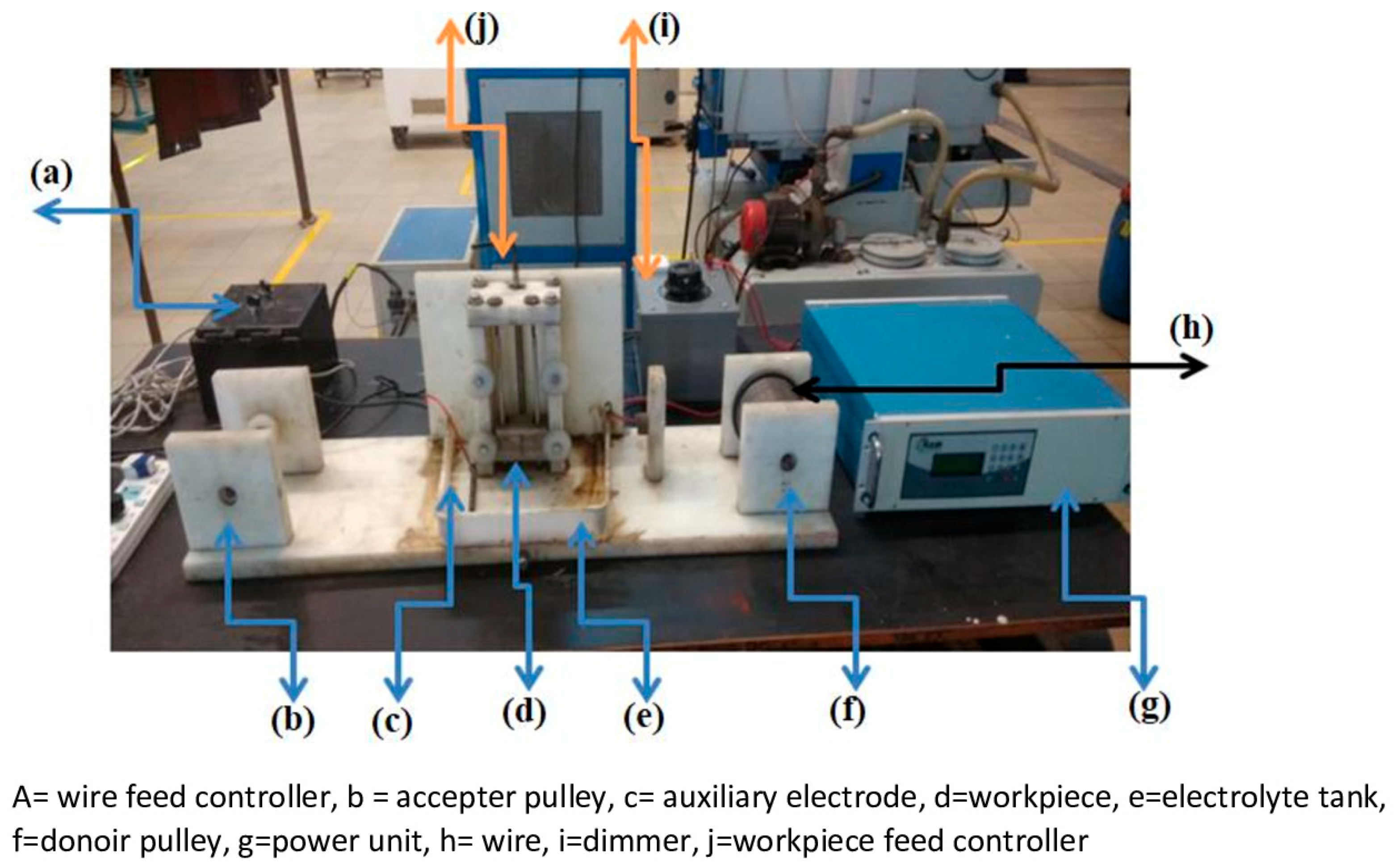
Table 2. The TW-ECDM setup was designed and developed and the major units of the setup are as follows: passive (auxiliary) and the active (wire) electrodes, machining chamber, pulse DC power supply, wire feed controller, tank (contained the electrolyte), workpiece clamping, and the feed mechanism as shown in Figure 2.
A polymer-based material was utilized for the setup fabrication due to its exceptional scratch- and chemical-resistant nature. The size of the electrolyte tank was 120 × 100 × 40 mm. The passive (auxiliary) electrode was made of a 20 mm diameter graphite rod that was 80 mm in length. In the proposed study, a pulse mode DC power supply with a maximum voltage of 220 V and a current of 6 A was deployed. The positive and negative ends were connected to the anode and cathode, respectively. For guiding the wire, the pulley was made of Teflon material to maintain proper tension. A NaOH electrolyte was selected over KOH for better performance [
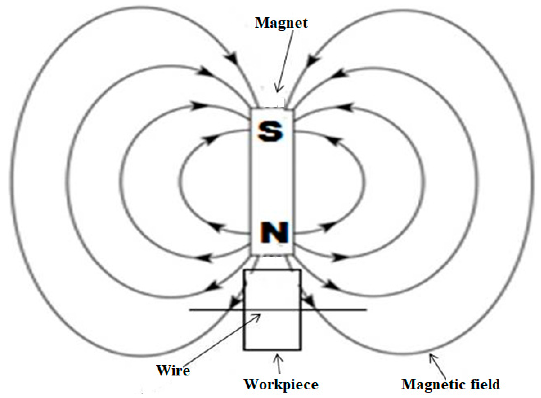
36]. In the present work, a neodymium permanent magnet (disc type) was used to produce magnetic fields and the properties of the magnet are presented in Table 3. The workpiece and magnet were kept at a right angle to each other to obtain a better magnetic effect, as depicted in Figure 3.
For the analysis of the experimental results, MINITAB-17 software (Gandhinagar, Gujarat, India) was used to evaluate the performance of the process. An L9 orthogonal array (OA) was used to consider the variable parameters of voltage, electrolyte concentration, and wire feed (speed). Three response parameters, namely, the material removal rate (MRR), length of cut (LOC), and surface roughness (Ra) were considered.

Initial Trials

The conditions for the initial trials are summarized in Table 4.
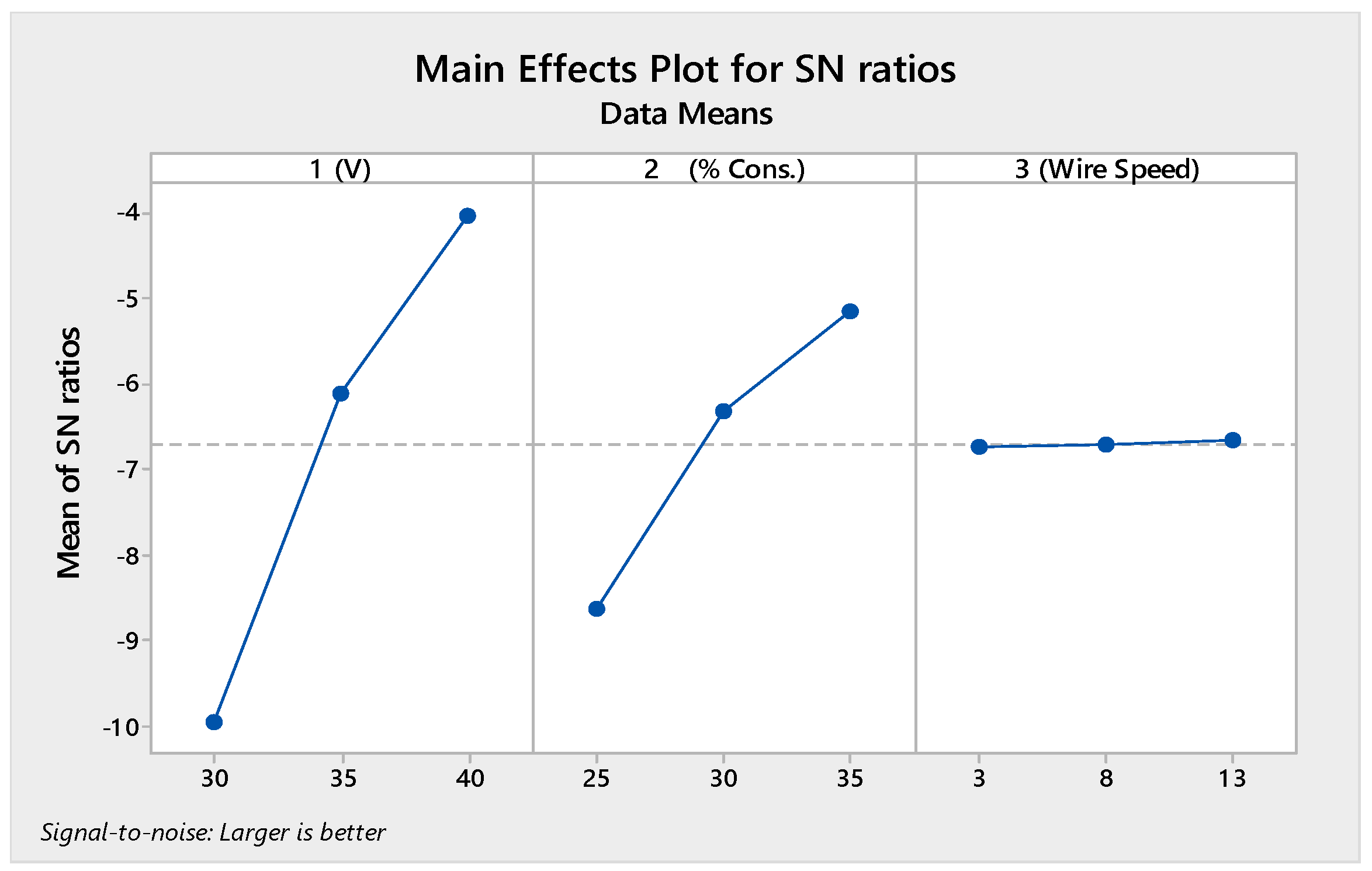
Based on the initial trials, the available literature, and experimental restrictions, the range of input process parameters was selected to be wire speed: 0–15 m/min, electrolyte concentration: 25 to 35 (g/L), and voltage: 30–40 V. During the experiment, three levels of each input process parameter were selected, which are shown in Table 5. In addition to the Taguchi method, analysis of variance (ANOVA) was used to measure the impact of each input process parameter on the MRR, LOC, and Ra. It also indicated the relative contribution of each input process parameter on the response. In the Taguchi design, the signal and noise represent the desired mean value and the undesirable (i.e., standard deviation) value of the output characteristics, respectively. In the present study, the interactions between the input machining parameters were neglected.
MRR was calculated using Equation (1):
M R R = ( W b W a t )
where Wb and Wa represent the weight of the workpiece before and after the experiment (mg/min), respectively, and t is the total machining time (min), where each experiment was designed for 10 min of machining time.
A METTLER TOLEDO model was used to measure the weight of the workpiece. To measure the LOC, a scanning electron microscope was used. A surface roughness tester (model no-ISR-S400) was used to measure Ra. Equations (2)–(4) show the improvement ratio calculations of MRR, LOC, and Ra, respectively:
M R R I m p r o v e m e n t ( % ) = ( M R R w m f M R R w o m f M R R w o m f ) × 100
where MRRwmf is the material removal rate with a magnetic field (MHD) and MRRwomf is the material removal rate without a magnetic field (MHD);
R a I m p r o v e m e n t ( % ) = ( R a w o m f R a w m f R a w o m f ) × 100
where 
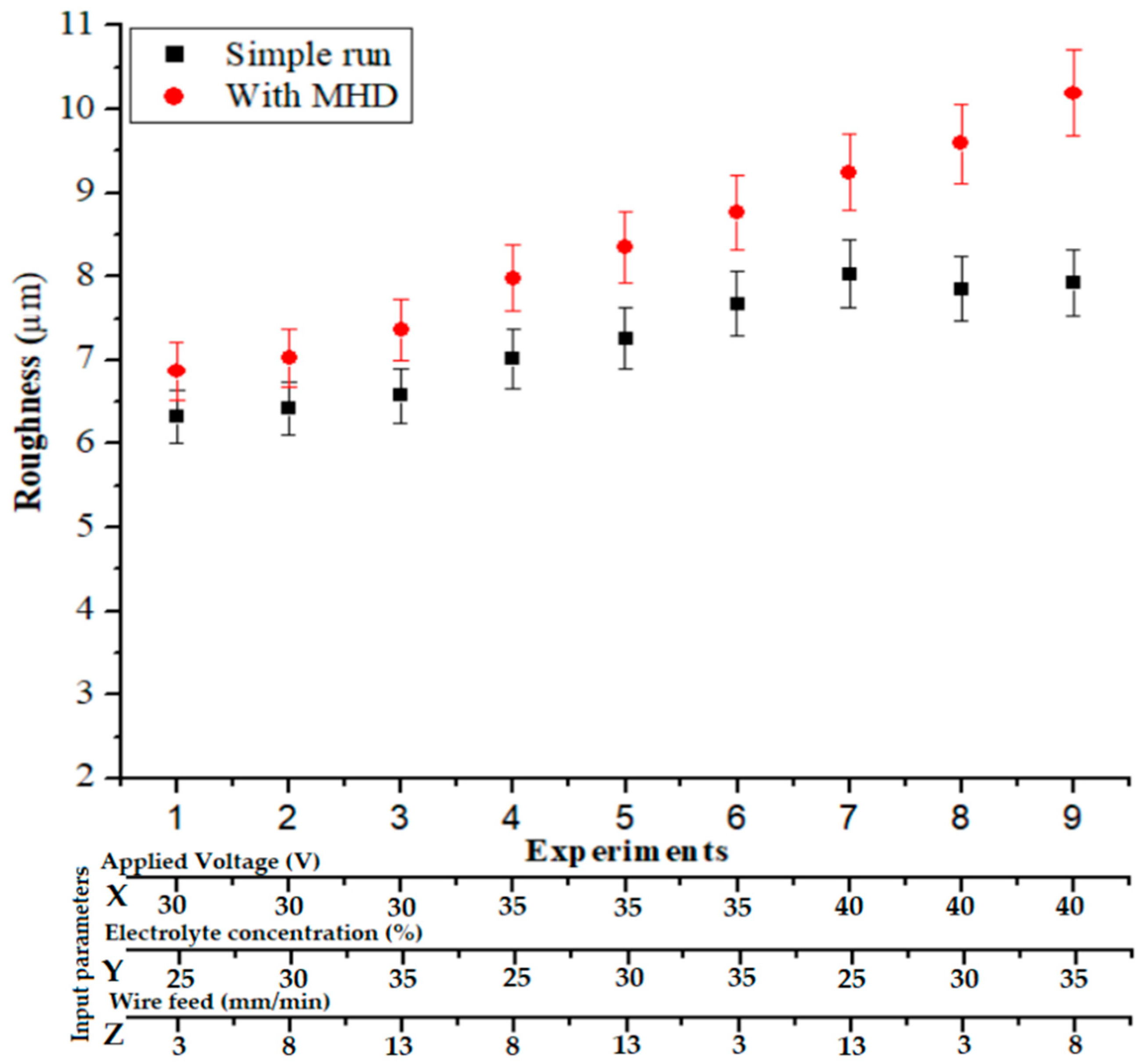
Rawmf is the surface roughness with a magnetic field (MHD) and Rawomf is the surface roughness without a magnetic field (MHD);
L O C I m p r o v e m e n t ( % ) = ( L O C w m f L O C w o m f L O C w o m f ) × 10
where LOCwmf is the length of cut with a magnetic field (MHD) and LOCwomf is the length of cut without a magnetic field (MHD).

3. Experimental Results and Discussion

Table 5 shows the combinations of input parameters for the response parameters as per the selected L9 orthogonal array. In the current study, the signal-to-noise (S/N) ratio was calculated for MRR and LOC based on larger being better and for Ra based on smaller being better. The S/N ratio was evaluated as per Equation (5) [49,50]: The S/N ratio values shown in Table 6.
S N = 10 × log ( mean square deviation )

3.1. Response Parameters

All the measured response parameters: material removal rate (MRR), Length of cut and Surface roughness (Ra) has been analyzed.

3.1.1. Material Removal Rate (MRR)

The best parametric set for all output parameters using the MHD method was found using L9 OA. Figure 4 demonstrates the signal-to-noise ratio plot for the MHD method for MRR. Table 7 shows the ANOVA table for the MRR response that was generated using the MHD method.
It is clear from Figure 4 and Table 7 that the voltage had the most important impact on the MRR, followed by the percentage of electrolyte concentration and wire speed. At low voltage, the sparking energy was lower, resulting in a lower MRR. Whenever the supply voltage increased, the rate of electrolysis increased, and therefore, high-intensity sparks were generated. Due to these high-intensity sparks, a larger crater was formed as compared to the lower-intensity sparks, resulting in a large quantity of material removed from the workpiece. With an increase in the concentration values, higher amounts of ions were available for electrolysis processes; hence, the rate of electrolysis was increased, and therefore, more bubbles were generated, which produced a stable highly dense gas film. This was responsible for the rise in MRR. The wire feed rate did not considerably affect the process performance. The optimal parametric set for the MRR was X3Y3Z3. The effect of increasing the machining voltage on the average maximum feed rate was greater than the effect of increasing the electrolyte concentration.

3.1.2. Length of Cut (LOC)

Figure 5 displays the SN ratio graph for the MHD method and Table 8 illustrates the ANOVA table for the LOC created using the MHD method; it is evident that the voltage provided the greatest impact on the LOC, followed by the wire speed and the concentration percentage. As explained regarding the MRR, an increase in applied voltage increased the rate of electrolysis; hence, high-intensity sparks and the formation of a large crater were observed, which was responsible for the production of a large slit/cut along the cutting direction. The percentage of the electrolyte concentration and the wire speed negligibly affected the process. The increased electrolyte concentration with an increased wire speed resulted in a higher amount of ions available for the electrolysis process. Hence, increases in the rate of electrolysis and cutting speed were responsible for the increase in the LOC. The optimal parametric set for the LOC was X3Y3Z3.

3.1.3. Surface Roughness (Ra)

Figure 6 illustrates the SN ratio graph and Table 9 demonstrates the ANOVA for Ra when using the MHD approach; it is evident that the voltage had a significant effect on Ra, followed by the electrolyte concentration and wire feed. As the voltage increased, the intensity of the sparks increased and side sparking also increased; therefore, a large crater was formed, which was responsible for generating coarse surfaces on the cutting area. As the wire speed increased, the tool electrode (wire) dragged the bubbles at a high speed away from the cutting area, resulting in an uneven spark that caused the rough surface. The optimal parametric set for Ra was X1Y1Z2.

3.2. Comparative Analysis

3.2.1. Material Removal Rate Analysis

Similar investigation conditions were also utilized during the analysis of the MRR with and without using the MHD approach. From Figure 7, it is clear that the MRR was significantly improved by 25.35% to 85.28% when using the MHD approach. In the MHD approach, the electrolyte distribution happened uniformly, allowing for more regular, steady, and high-intensity sparks to produce more hydrogen bubbles. However, in comparison with the approach without MHD, the electrolyte-enhanced stirring effect increased the MRR. Under the magnetic field at right angles to the electric field, a Lorentz force was produced, which was responsible for stirring the ions in the narrow gap between the tool wire and quartz. This could increase the void fraction and uncover the gas bubble’s surface. Furthermore, the electrolyte movement increased and removed the burrs from the quartz. Additionally, the coating on the wire increased the wire’s strength, prevented wire breakage, and increased the MRR and machining efficiency. The concentration of the solution generally affected both the dimensions of the channels created using chemical etching and the concentration of the spark energy, where the spark intensity affected the dimensions of the channels created by the process. Furthermore, when it was difficult to extend the electrolyte to the wire (tool), a downward force was exerted on the tool wire, which gently moved the tool toward the workpiece. At lower depths, the electrolyte easily reached the cutting area, where the removal of materials and continued chemical etching was more easily achieved. Due to the electric sparks striking the workpiece, which increased the local temperature and reduced the material viscosity, chemical corrosion occurred in a more favorable environment. In this area, the electric sparks were the main determinant of the material removal rate, and thus, it can be stated that machining was achieved in the electric discharge regime.

3.2.2. Length of Cut Analysis

Similar investigation conditions were also utilized to analyze the LOC with and without using the MHD approach. Figure 8 shows an improvement in the LOC under the influence of a magnetic field by 7.04% to 48.86%. In the MHD method, the constant stirring caused a high-strength spark such that a large volume of material was removed from the quartz glass across the machining direction; due to the uniform electrolytic movement, this reduced overcut and increased the LOC. The electrolytic concentration affected the chemical etching regarding the magnitudes of the channels created and the concentration of the spark energy, where the spark intensity affected the dimensions of the microslits created by the process. Because the increase in voltage enhanced the sparks, this also improved the channel length. On the other hand, the presence of the sparks that jumped from the bottom of the tool to the workpiece played a major role in the material removal and determined the channel size. Increasing the voltage amplified the sparks and increased the length of the channel.

3.2.3. Surface Roughness (Ra) Analysis

To analyze the effects of machining without and with using the MHD approach on Ra, the same experimental conditions were used. From Figure 9, under the use of the MHD method, the average surface roughness decreased by 30.39%.to 9.06%. An increase in the applied voltage led to increased electrolysis formation, which caused high-strength sparks and, consequently, the generation of a bigger cavity that produced an irregular profile. The electrolyte stirring effect gave a finer surface profile than with the MHD method. Furthermore, debris was removed during the operation. During the MHD method, the electrolysis phenomenon was more steady and the sparking was higher at a higher level of electrolyte concentration; therefore, a fine average surface roughness with lower overcut was created. The more stable the gas film, the less time out of the whole machining process was devoted to forming the gas film, and the more time was devoted to the electric discharge, resulting in more spark energy. Increasing the spark energy led to more material removed per spark, resulting in a lower surface quality.

3.3. Mathematical Models and the Additivity Test

Multiple regression analysis was utilized to establish the correlations between the regulating process variables and the response features by adjusting the linear equation for the experimental values. The interaction of variable parameters was not considered due to L9 OA selection. Under two separate working conditions (with and without the MHD approach), the following mathematical equations could be used to model the machining of quartz glass with wire-ECDM, where Equations (6)–(8) show the mathematical models for the without-MHD run (simple run) for MRR, LOC, and Ra, respectively:
M R R = 0.4390 + 0.01390 × ( X ) + 0.00931 × ( Y ) 0.00173 × ( Z )
L O C = 3570 + 138.26 × ( X ) + 11.27 × ( Y ) + 5.93 × ( Z )
R a = 2.834 + 0.25907 × ( X ) + 0.07377 × ( Y ) 0.00897 × ( Z )
Equations (9)–(11) show the mathematical models for the with-MHD run for MRR, LOC, and Ra, respectively:
M R R = 1.171 + 0.03173 × ( X ) + 0.01902 × ( Y ) 0.00286 × ( Z )
L O C = 5264 + 179.2 × ( X ) + 38.49 × ( Y ) 5.50 × ( Z )
R a = 1.201 + 0.1494 × ( X ) + 0.0267 × ( Y ) + 0.0001 × ( Z )
where X is the voltage (V), Y is the % electrolyte concentration (g/L), Z is the wire speed (m/min).
These mathematical models needed to be validated if it was to support an intermediary combination of process variables without a standard orthogonal array; hence, trials were run to check their validity. Table 10 represents the selected set of process variables and the response values. The error percentage demonstrates the slight deviation of the experimental value from the result predicted by the regression equations within limits. Furthermore, Table 11 shows the additivity test for the optimal parametric set.

3.4. Surface Profile Analysis Using SEM

Figure 10a,b shows the SEM images of the microslit produced on the quartz workpiece at 30 V, a 25% electrolyte concentration, and a 3 m/min wire speed for both the conventional and MHD-assisted processes. For the conventional process, the machined profile was found to have been rough and somewhat inconsistent. Figure 10b depicts the microslits in the workpiece under the application of MHD for the same parameter settings. The magnetic field assisted with eliminating the surface irregularities from the machined workpiece; therefore, the machined slits were found to be straighter with an enhanced cutting profile.

4. Conclusions

In this research, microslits with high aspect ratios were effectively fabricated on quartz via the MHD-assisted TW-ECDM process using a coated wire. A set of experiments with a lab-developed magnetically assisted TW-ECDM facility were conducted to study the magnetic field output effects. The effects of the voltage, percentage of concentration, and wire speed on the MRR, LOC, and Ra were presented. The following findings can be reported based on the experiments:
  • The proposed magnet-assisted TW-ECDM process that used a zinc-coated brass wire was a useful method for microslit fabrication with a high aspect ratio on quartz material. The MHD method improved the electrolysis and reduced the burrs from the small gap between the workpiece and the tool wire.
  • Due to the magnetic flux density over the current density, the electrolysis process was significantly improved. When using the MHD method, the MRR was increased from 25.35 to 85.28% in comparison to the non-MHD approach. Furthermore, the LOC improved by 7.04% to 48.86% for the MHD approach. 25
  • The electrolytic concentration affected the chemical etching regarding both the magnitudes of the channels created and the concentration of the spark energy, where the spark intensity affected the dimensions of the microslits created by the process. Furthermore, when using the MHD method, a decrease in the surface roughness percentage was found to vary from 30.39% to 9.06% in comparison to the non-MHD method.
  • Increasing the spark energy led to more sparking, resulting in a lower surface quality. The SEM image analysis showed better surface quality with the use of a coated wire during machining. The use of a coated wire minimized wire breakage and improved the effectiveness of machining, the MRR, the LOC, and the cutting speed. Moreover, electrolyte losses were reduced, resulting in lower costs and less environmental contaminants.

Author Contributions

A.D.O.: conceptualization, experimentation, resources, data curation, experimental setup, design of the experiments, measurements, writing—original draft, writing—review and editing. A.K.: validation, resources, project administration, visualization, supervision, writing—review and editing. V.B.: validation, resources, visualization, supervision, writing—review and editing. A.A.: writing—review and editing, validation, visualization, supervision. M.K.: writing—original draft preparation, conceptualization, methodology, software, formal analysis, design of the experiments. C.I.P.: formal analysis, design of the experiments, writing—review and editing. T.S.: formal analysis, design of the experiments, writing—review and editing. All authors have read and agreed to the published version of the manuscript.

Funding

This research was fully funded by the Office of Research and Sponsored Program (ORSP), Pandit Deendayal Energy University (P.D.E.U.), Gandhinagar-Gujarat, India. Project number: ORSP/R&D/SRP/2017/AOAK.

Institutional Review Board Statement

Not applicable.

Informed Consent Statement

Not applicable.

Data Availability Statement

The data are available from the corresponding author upon request.

Conflicts of Interest

The authors declare no conflict of interest.

References

  1. Fiorini, G.S.; Chiu, D.T. Disposable microfluidic devices: Fabrication, function, and application. Biotechniques 2005, 38, 429–446. [Google Scholar] [CrossRef] [Green Version]
  2. Liu, L.; Jiang, Z.; Rahman, S.; Shams, M.I. Bin; Jing, B.; Kannegulla, A.; Cheng, L.J. Quasi-optical terahertz microfluidic devices for chemical sensing and imaging. Micromachines 2016, 7, 75. [Google Scholar] [CrossRef] [PubMed] [Green Version]
  3. Bilal, A.; Jahan, M.; Talamona, D.; Perveen, A. Electro-Discharge Machining of Ceramics: A Review. Micromachines 2018, 10, 10. [Google Scholar] [CrossRef] [PubMed] [Green Version]
  4. Rolf Wuthrich, J.D.A.Z. Copyright. In Micromachining Using Electrochemical Discharge Phenomenon; Elsevier: Amsterdam, The Netherlands, 2015; p. iv. ISBN 9780323241427. [Google Scholar]
  5. Peng, W.Y.; Liao, Y.S. Study of electrochemical discharge machining technology for slicing non-conductive brittle materials. J. Mater. Process. Technol. 2004, 149, 363–369. [Google Scholar] [CrossRef]
  6. Nycz, M.; Arkusz, K.; Pijanowska, D.G. Influence of the silver nanoparticles (AgNPs) formation conditions onto titanium dioxide (TiO2) nanotubes based electrodes on their impedimetric response. Nanomaterials 2019, 9, 1072. [Google Scholar] [CrossRef] [Green Version]
  7. Mandal, A.; Dixit, A.R.; Chattopadhyaya, S.; Paramanik, A.; Hloch, S.; Królczyk, G. Improvement of surface integrity of Nimonic C 263 super alloy produced by WEDM through various post-processing techniques. Int. J. Adv. Manuf. Technol. 2017, 93, 433–443. [Google Scholar] [CrossRef]
  8. Arkusz, K.; Nycz, M.; Paradowska, E. Electrochemical evaluation of the compact and nanotubular oxide layer destruction under ex vivo ti6al4v eli transpedicular screw implantation. Materials (Basel) 2020, 13, 176. [Google Scholar] [CrossRef] [Green Version]
  9. Kumar, M.; Satsangi, P.S. A study on machining performance of wire electric discharge grinding (WEDG) process during machining of tungsten alloy micro-tools. Sadhana Acad. Proc. Eng. Sci. 2021, 46. [Google Scholar] [CrossRef]
  10. Kumar, S.; Dvivedi, A. On machining of hard and brittle materials using rotary tool micro-ultrasonic drilling process. Mater. Manuf. Process. 2019, 34, 736–748. [Google Scholar] [CrossRef]
  11. Varel, H.; Ashkenasi, D.; Rosenfeld, A.; Wähmer, M.; Campbell, E.E.B. Micromachining of quartz with ultrashort laser pulses. Appl. Phys. A Mater. Sci. Process. 1997, 65, 367–373. [Google Scholar] [CrossRef]
  12. Huang, Z.; Feng, C.L. Study of machining microchannels on quartz by the laser-induced plasma. Adv. Mater. Res. 2011, 154–155, 1655–1658. [Google Scholar] [CrossRef]
  13. Qin, S.J.; Li, W.J. Micromachining of complex channel systems in 3D quartz substrates using Q-switched Nd:YAG laser. Appl. Phys. A Mater. Sci. Process. 2002, 74, 773–777. [Google Scholar] [CrossRef]
  14. Qi, H.; Fan, J.; Wang, J. A study of the micro-machining process on quartz crystals using an abrasive slurry jet. Proc. Inst. Mech. Eng. Part B J. Eng. Manuf. 2015, 229, 421–434. [Google Scholar] [CrossRef]
  15. Hu, M.F.; Xie, J.; Su, H.H.; Liu, J.N. Study on laser-assisted dry micro-ground surface of difficult-to-cut materials. Int. J. Adv. Manuf. Technol. 2018, 94, 2919–2928. [Google Scholar] [CrossRef]
  16. Kumar, V.; Singh, H. Rotary Ultrasonic Drilling of Silica Glass BK-7: Microstructural Investigation and Process Optimization Through TOPSIS. Silicon 2019, 11, 471–485. [Google Scholar] [CrossRef]
  17. Sindhu, D.; Thakur, L.; Chandna, P. Parameter Optimization of Rotary Ultrasonic Machining on Quartz Glass Using Response Surface Methodology (RSM). Silicon 2019. [Google Scholar] [CrossRef]
  18. Jain, V.K.; Chak, S.K. Electrochemical spark trepanning of alumina and quartz. Mach. Sci. Technol. 2000, 4, 277–290. [Google Scholar] [CrossRef]
  19. Lin, Y.-C.; Lee, C.-C.; Lin, H.-S.; Hong, Z.-H.; Hsu, F.-C.; Hung, T.-P.; Lyu, Y.-T. Fabrication of microfluidic structures in quartz via micro machining technologies. Microsyst. Technol. 2017, 23, 1661–1669. [Google Scholar] [CrossRef]
  20. Oza, A.D.; Kumar, A.; Badheka, V.; Arora, A. Traveling Wire Electrochemical Discharge Machining (TW-ECDM) of Quartz Using Zinc Coated Brass Wire: Investigations on Material Removal Rate and Kerf Width Characteristics. Silicon 2019, 11, 2873–2884. [Google Scholar] [CrossRef]
  21. Kumar, M.; Vaishya, R.O.; Suri, N.M.; Manna, A. An Experimental Investigation of Surface Characterization for Zirconia Ceramic Using Electrochemical Discharge Machining Process. Arab. J. Sci. Eng. 2020. [Google Scholar] [CrossRef]
  22. Banker, K.S.; Oza, A.D.; Dave, R.B. Performance Capabilities of EDM machining using Aluminum, Brass and Copper for AISI 304L Material. Int. J. Appl. Innov. Eng. Manag. 2013, 2, 186–191. [Google Scholar]
  23. Kumar, M.; Vaishya, R.O.; Oza, A.D.; Suri, N.M. Experimental Investigation of Wire-Electrochemical Discharge Machining (WECDM) Performance Characteristics for Quartz Material. Silicon 2020, 12, 2211–2220. [Google Scholar] [CrossRef]
  24. Vaishya, R.O.; Oza, A.D.; Gupta, A. Multiple Parameter Optimization by Wire Electrochemical Discharge Machining Process on Quartz Glass. In Advances in Manufacturing Processes Select Proceedings of RAM 2020; Springer: Singapore, 2021; pp. 71–86. [Google Scholar]
  25. Mezquita, J.; Pau, M.; Mezquita, C. A novel carbonic anhydrase II mRNA isolated from mature chicken testis displays a TATA box and other promoter sequences in a leader 5′ untranslated region not present in somatic tissues. Gene 1994, 147, 231–235. [Google Scholar] [CrossRef]
  26. Bian, J.; Ma, B.; Liu, X.; Qi, L. Experimental study of toolwear in electrochemical discharge machining. Appl. Sci. 2020, 10, 5039. [Google Scholar] [CrossRef]
  27. Oza, A.D.; Kumar, A.; Badheka, V.; Nema, A.; Kumar, M. Quartz Micro-machining Using Wire Electrochemical Spark Machining Process. In Advances in Manufacturing Processes Select Proceedings of RAM 2020; Springer: Singapore, 2021; pp. 95–109. ISBN 978-981-15-9116-7. [Google Scholar]
  28. Singh, T.; Dvivedi, A.; Arya, R.K. Fabrication of micro-slits using W-ECDM process with textured wire surface: An experimental investigation on kerf overcut reduction and straightness improvement. Precis. Eng. 2019, 59, 211–223. [Google Scholar] [CrossRef]
  29. Chen, Y.; Feng, X.; Xin, G. Experimental Study on Ultrasonic Vibration-Assisted WECDM of Glass Microstructures with a High Aspect Ratio. Micromachines 2021, 12, 125. [Google Scholar] [CrossRef] [PubMed]
  30. Oza, A.D.; Kumar, A.; Badheka, V. Micro-Machining Characteristics of Quartz Using Travelling Wire-Electrochemical Discharge Machining (TW-ECDM) Process. In Proceedings of the International Conference on Precision, Meso, Micro and Nano Engineering (Copen-11), IIT Indore, India, 12–14December 2019. [Google Scholar]
  31. Ziki, J.D.A.; Wüthrich, R. Tool wear and tool thermal expansion during micro-machining by spark assisted chemical engraving. Int. J. Adv. Manuf. Technol. 2012, 61, 481–486. [Google Scholar] [CrossRef]
  32. Jain, V.K.; Rao, P.S.; Choudhary, S.K.; Rajurkar, K.P. Experimental Investigations into Traveling Wire Electrochemical Spark Machining (TW-ECSM) of Composites. J. Eng. Ind. 1991, 113, 75–84. [Google Scholar] [CrossRef]
  33. Kuo, K.Y.; Wu, K.L.; Yang, C.K.; Yan, B.H. Wire electrochemical discharge machining (WECDM) of quartz glass with titrated electrolyte flow. Int. J. Mach. Tools Manuf. 2013, 72, 50–57. [Google Scholar] [CrossRef]
  34. Kuo, K.Y.; Wu, K.L.; Yang, C.K.; Yan, B.H. Effect of adding SiC powder on surface quality of quartz glass microslit machined by WECDM. Int. J. Adv. Manuf. Technol. 2015, 78, 73–83. [Google Scholar] [CrossRef]
  35. Manna, A.; Kundal, A. An experimental investigation on fabricated TW-ECSM setup during micro slicing of nonconductive ceramic. Int. J. Adv. Manuf. Technol. 2013, 76, 29–37. [Google Scholar] [CrossRef]
  36. Yang, C.T.; Song, S.L.; Yan, B.H.; Huang, F.Y. Improving machining performance of wire electrochemical discharge machining by adding SiC abrasive to electrolyte. Int. J. Mach. Tools Manuf. 2006, 46, 2044–2050. [Google Scholar] [CrossRef]
  37. Singh, Y.P.; Jain, V.K.; Kumar, P.; Agrawal, D.C. Machining piezoelectric (PZT) ceramics using an electrochemical spark machining (ECSM) process. J. Mater. Process. Technol. 1996, 58, 24–31. [Google Scholar] [CrossRef]
  38. Liu, J.W.; Yue, T.M.; Guo, Z.N. Wire electrochemical discharge machining of Al2O3 particle reinforced aluminum alloy 6061. Mater. Manuf. Process. 2009, 24, 446–453. [Google Scholar] [CrossRef]
  39. Bhuyan, B.K.; Yadava, V. Modelling and optimisation of travelling wire electro-chemical spark machining process. Int. J. Ind. Syst. Eng. 2014, 18, 139. [Google Scholar] [CrossRef]
  40. Mitra, N.S.; Doloi, B.; Bhattacharyya, B. Predictive analysis of criterial yield during travelling wire electrochemical discharge machining of Hylam based composites. Adv. Prod. Eng. Manag. 2015, 10, 73–86. [Google Scholar] [CrossRef] [Green Version]
  41. Bhuyan, B.K.; Yadava, V. Experimental study of traveling wire electrochemical spark machining of borosilicate glass. Mater. Manuf. Process. 2014, 29, 298–304. [Google Scholar] [CrossRef]
  42. Yadav, P. Experimental Investigation for Performance Study of Wire Electrochemical Spark Cutting of Silica Epoxy Nanocomposites. Silicon 2019. [Google Scholar] [CrossRef]
  43. Oza, A.D.; Kumar, A.; Badheka, V. Improving quartz micro-machining performance by magnetohydrodynamic and zinc-coated assisted traveling wire-electrochemical discharge machining process. Mater. Today Proc. 2020, 28, 970–976. [Google Scholar] [CrossRef]
  44. Liu, Y.; Wei, Z.; Wang, M.; Zhang, J. Experimental investigation of micro wire electrochemical discharge machining by using a rotating helical tool. J. Manuf. Process. 2017, 29, 265–271. [Google Scholar] [CrossRef]
  45. Kumar, U.; Singh, M.; Singh, S. Wire-Electrochemical Discharge Machining of SiC Reinforced Z-Pinned Polymer Matrix Composite Using Grey Relational Analysis. Silicon 2020. [Google Scholar] [CrossRef]
  46. Singh, J.; Vaishya, R.; Kumar, M. Fabrication of micro features on quartz glass using developed WECDM setup. ARPN J. Eng. Appl. Sci. 2019, 14, 725–731. [Google Scholar]
  47. Maher, I.; Sarhan, A.A.D.; Hamdi, M. Review of improvements in wire electrode properties for longer working time and utilization in wire EDM machining. Int. J. Adv. Manuf. Technol. 2014, 76, 329–351. [Google Scholar] [CrossRef] [Green Version]
  48. Sen, R.; Choudhuri, B.; Barma, J.D.; Chakraborti, P. Surface integrity study of WEDM with various wire electrodes: Experiments and analysis. Mach. Sci. Technol. 2020, 24, 569–591. [Google Scholar] [CrossRef]
  49. Singh, T.; Gangil, B.; Ranakoti, L.; Joshi, A. Effect of silica nanoparticles on physical, mechanical and wear properties of 509 natural fiber reinforced polymer composites. Polym. Compos. 2021. [Google Scholar] [CrossRef]
  50. Singh, T.; Gangil, B.; Singh, B.; Verma, S.K.; Biswas, D.; Fekete, G. Natural-synthetic fiber reinforced homogeneous and 511 functionally graded vinylester composites: Effect of bagasse-Kevlar hybridization on wear behaviour. J. Mater. Res. Technol. 2019, 8, 5961–5971. [Google Scholar] [CrossRef]
Figure 1. The TW-ECDM process [20].
Materials 14 02377 g001
Figure 2. The TW-ECDM setup.
Materials 14 02377 g002
Figure 3. Positioning of the magnet and the workpiece [43].
Materials 14 02377 g003
Figure 4. SN ratio plot for the MRR.
Materials 14 02377 g004
Figure 5. SN ratio graph for LOC.
Materials 14 02377 g005
Figure 6. SN ratio graph for the LOC.
Materials 14 02377 g006
Figure 7. MRR with and without the MHD method being used.
Materials 14 02377 g007
Figure 8. LOC (μm) with and without using the MHD method.
Materials 14 02377 g008
Figure 9. Ra (μm) with and without using the MHD method.
Materials 14 02377 g009
Figure 10. SEM images of slits produced (a) without using the MHD approach and (b) using the MHD approach.
Materials 14 02377 g010
Table 1. Types of wire (tool electrode) used TW-ECDM processes [20].
Ref.Wire MaterialSize of Wire (Diameter)Workpiece MaterialObservations
[5]Stainless steel wire 0.25 mmOptical glass, quartz, and ceramic (Al2O3)Strong pulse DC supply was used to machine hard nonconducting materials.
[20]Zinc-coated brass wire0.15 mmQuartzCoated wire reduced the wire breakage and higher average surface roughness was observed because of craters, which could be minimized by providing flushing arrangements during the machining operation.
[23]Zinc-coated brass wire0.15 mmQuartzAt a higher voltage and electrolyte concentration level, thin cracks with slim necking were observed at the opening of the machined surface. Furthermore, during machining, the debris became embedded at the workpiece and in the machining zone.
[28]Textured Stainless-304 wire0.20 mmBorosilicate glassTextured wire improved the localized electric field intensity. Lower ECD energy decreased the straightness of the microslits due to the edge-chipping effect.
[29]Tungsten0.05 mmQuartz glassUltrasonic vibration refined the gas film’s thickness, improved the slit quality, and reduced the critical voltage.
[34]Brass wire0.15 mmQuartzBy using a SiC powder-mixed titrated electrolytic flow, the surface quality and machining precision was improved.
[35]Steel wire 0.070 and 0.090 mmAl2O3 ceramicBurrs, surface roughness, and slit expansion could be minimized by providing proper electrolyte flow.
[36]Brass wire0.25 mmGlass and quartzThe reciprocating mechanism was beneficial for the machining of the irregular cross-section. Adding abrasive particles in the electrolyte reduced the slit expansion and improved the quality of the machined cut.
[37]Brass wire0.50 mmZirconate titanateAt higher voltages, large crack propagation and a slight workpiece melting phenomenon were observed.
[38]Molybdenum wire0.18 mmAl2O3-particle-reinforced 6061 aluminum alloyA longer pulsating supply reduced the MRR and improve the quality of surface and slit
[39]Brass wire0.25 mmBorosilicate glassPulse DC power reduced the surafce roughness and Improve the material removal rate (MRR)
[40]Brass wire0.25 mmHylam-based compositeUnder different experimental conditions, the surface finish, kerf width, and MRR improved.
[41]Brass wire0.25 mmBorosilicate glassUsing a pulsed DC supply improved the MRR and reduced the kerf width via a selection of proper pulse on and off timings.
[42]Brass wire0.2 mmSilica–epoxy nanocompositesAt higher voltages, the MRR and roughness were higher because of a decrease in the silica particle concentration.
[43]Zinc-coated brass wire0.15 mmQuartzThe MRR increased from 21.47 to 75.82% and the surface roughness reduced from 22.25% to 7.93% under the application of the MHD approach with NaOH as an electrolyte.
[44]Tungsten0.1 mmGlassA rotating helical tool was proposed to construct a series of kerfs with a high aspect ratio. The gas film thickness could be increased using a proper electrolysis process.
[45]Ni-coated brass wire0.25 mmSiC-reinforced z-pinned polymer matrix compositesNonuniform cutting with a high diametrical overcut and lower material removal rate was observed.
[46]Zn-coated brass wire Quartz glassWire breakage occurred frequently and higher surface roughness, chips, and burrs were observed during machining of the surface.
Table 2. Selected properties of quartz glass [20].
ParametersValues
Thermal expansion coefficient (20–320 °C)5.11 × 10⁻⁷ cm/cm·°C
Density2.2 × 103 kg/m3
Hardness5.5–6.5 Mohs scale (N/mm2)
Dimension75(L) × 25(W) × 2(T) mm
Tensile strength50 × 107 Pa (N/m2)
Young’s modulus7.2 × 1010 Pa
Table 3. Selected properties of the magnet.
VariantDiameterLengthMagnetic Field
Nd-Fe-B
magnet (disc)
20 mm10 mm0.38 to 0.45 T (approx.) at the top surface
Table 4. Initial trial conditions.
ParametersRangeObservation
Voltage range<10 VNo electrolysis process was observed.
10–20 VGas bubble formation was low, resulting in poor sparking.
20–30 VLow intensity of sparking with uniform electrolysis.
30–40 VElectrolysis rate was higher and the spark intensity was uniform and higher.
Above 42 VUnstable sparking led to frequent wire breakage.
Percentage of electrolyte concentration rage<22%Very narrow sparking was observed.
22–40%Sufficient and smooth sparking was observed.
Above 40%Uneven side sparking with high-strength sparking.
Wire speed (m/min)<0–3 m/minWire breakage phenomenon with a coarse machined surface.
Between 3–13 m/minWire breakage phenomenon was lessened and side sparking was reduced.
Above 14 m/minCutting action was poor.
Table 5. Factors with their associated levels.
FactorsInput ParametersLevels
123
XApplied voltage (V)303540
YElectrolyte concentration (%)253035
ZWire feed (mm/min)3813
Table 6. S/N ratio for response parameters.
Exp. No.Factor LevelsS/N Ratio
XYZMRRLOCRa
1111−11.845385460.82982754−16.023956
2122−9.6719370360.71603662−16.156110
3133−8.3723862361.44080477−16.35395
4212−8.0636612864.10852656−16.919315
5223−5.5852404666.0414644−17.211551
6231−4.6910996465.60068046−17.698171
7313−5.9893868667.63446418−18.092147
8321−3.6579519167.56984763−17.898499
9332−2.3928760168.07781164−17.979985
Table 7. ANOVA for the MRR for the MHD approach.
FactorDOFSSMSF-Valuep-ValueContribution (%)
X20.151840.0759248.280.0271.672
Y20.0554290.02771417.620.05426.162
Z20.001440.000720.460.6860.679
Error20.0031450.001573 0.014
Total80.211862 98.529
Model Summary: R2—98.52%, R2Adj—94.06%
Table 8. ANOVA for the LOC for the MHD approach.
FactorDOFSSMSF-Valuep-ValueContribution (%)
X24,821,5412,410,770296.830.00395.034
Y2230,663115,33214.200.0660.045
Z2500325010.310.7650.098
Error216,2448122 0.320
Total85,073,450 95.499
Model Summary: R2—99.68%, R2Adj—98.72%
Table 9. ANOVA for the LOC for the MHD approach.
FactorDOFSSMSF-Valuep-ValueContribution (%)
X23.3781.68935.40.02792.64934573
Y20.1190.0591.20.4443.276678725
Z20.0530.0260.50.6421.457459676
Error20.0950.047 2.616790133
Total83.646 100.0002743
Model Summary: R2—97.38%; R2Adj—89.53%
Table 10. Additivity test.
Random Parametric Set for the Simple Runs
TW-ECDM ParametersMRRRaLOC
XYZABCABCABC
3035130.26840.28134.827.3567.403440.644991.151049.345.87
403030.39920.3911−2.069.5869.714991.3272289.132316.291.18
302530.21050.20552.46.8726.755441.69925.61877.345.5
Random Parametric Set for the MHD Runs
TW-ECDM ParametersMRRRaLOC
XYZABCABCABC
3035130.38140.409426.8436.5726.61880.7071329.151387.654.215
403030.65630.660220.5937.8517.97831.5953048.523042.2−0.207
302530.25570.24782−3.186.3276.35080.3741100.251057.75−4.017
where A signifies experimental values, B signifies mathematical equation values, and C signifies the error (%).
Table 11. Additivity test for the optimal parametric set.
Optimal Parametric Set for the MHD Run
MRR (mg/min)Ra (μm)LOC (μm)
0.80426.2473415.29
Publisher’s Note: MDPI stays neutral with regard to jurisdictional claims in published maps and institutional affiliations.

