1. Introduction
Particulate materials of different morphologies based on noble metals exhibit properties promising for practical applications. Pd-, Au- and Pt-based materials attract a lot of attention, as indicated by a large number of publications on their preparation and properties [
1,
2]. Noble metals are promising for electrocatalysis [
3], electrochemical biosensors [
4], energy conversion/storage devices, and fuel cells [
5]. Separate particles of noble metals and porous materials are obtained [
6]. The cost of the noble metals is a factor significantly limiting their large-scale application [
7,
8]. Alloying with base metals allows reducing the consumption of the noble metals. Studies show that the catalytic activity of alloys containing inexpensive (base) metals can be higher than that of the pure (unalloyed) noble metals [
6,
9].
Among a variety of noble metal-based particles and porous alloys, Fe-Pd alloys are of particular interest. The Fe-Pd alloys show the following functional properties: catalytic activity [
10,
11], magnetic shape memory (for the Fe
70Pd
30 composition) [
12], surface-enhanced Raman scattering [
13], and hydrogen absorption (Pd-rich alloy) [
14,
15]. Fe/Pd particles showed an electrocatalytic effect when compared with Pd [
16]. The properties of Fe-Pd alloys depend on their composition and structural characteristics [
17,
18,
19,
20].
The Fe-Pd alloys can be prepared by different methods. A porous PdFe alloy was fabricated through one-step mild dealloying of a PdFeAl ternary source alloy in NaOH solution [
21]. Thin films of Pd were obtained by the selective dissolution of iron in HCl solution from Fe
75Pd
25 films deposited on a gold-coated silicon oxide substrate [
13,
22]. In ref. [
20], a Fe-Pd alloy was formed by combining electrodeposition and selective dissolution. Pd/Fe wire electrodes were prepared via a galvanic replacement reaction between tetrachloropalladate (PdCl
42−) and a Fe wire [
23]. Fe-Pd alloy particles were obtained by reducing a mixture of iron and palladium compounds by sodium borohydride [
24,
25]. In ref. [
26], monodisperse FePd particles were prepared by polyol reduction of palladium acetylacetonate and thermal decomposition of iron pentacarbonyl. It was shown that particles of Fe
35Pd
65 can be obtained via the thermal decomposition of metal–organic compounds of iron and palladium [
27]. The Fe-Pd alloys can also be produced by physical methods. For example, Fe@Pd, Fe@Pt, and Fe@Au core–shell particles supported by silicon carbide were prepared by plasma sputtering deposition [
28].
Galvanic replacement is a promising method of the formation of metallic coatings and preparation of core–shell structures [
29,
30,
31,
32,
33]. This method is quite simple from the technological perspective. In this process, particles/objects of less noble metals of different sizes and morphologies are used as templates to tailor the structural characteristics of the resultant materials enriched with a more noble metal. The selective dissolution of less noble metals from the binary alloys obtained by galvanic replacement allows forming hollow particles and porous materials. In this manner, porous Au, Pt, Pd, Ru, Cu and Ni can be produced by dissolving a less noble metal from the corresponding alloys.
Fe-Pd powders have been obtained by galvanic replacement reaction starting from iron nanocubes as templates [
16]. To the best of our knowledge, no study has been conducted on the formation of Fe-Pd alloys by galvanic replacement reaction using micrometer-sized iron templates. These templates are widely available as commercial powders. In the present work, we investigated the morphological and phase transformations occurring upon galvanic replacement of iron by palladium, annealing of the products and selective dissolution of iron from the synthesized powder alloys. The goal of the study was to trace the structural evolution in the synthesized alloys and determine factors responsible for the structural changes.
2. Materials and Methods
Fe@Pd core–shell microparticles were synthesized by galvanic replacement reaction. Carbonyl iron (99.9%, “SyntezPKZh”, Dzerzhinsk, Russia) was used as a reactant and a template.
The iron powder was placed in a solution of PdCl2 in HCl acid for 3 min. Then, the solution was filtrated, and the residue was washed with deionized water several times and dried at room temperature. The concentration of PdCl2 in solution was selected such that ensured a Fe/Pd atomic ratio in the product of galvanic replacement of 4:1 upon full reduction of palladium ions.
The product of galvanic replacement was annealed in vacuum at 800 °C for 30 min.
Acid treatment of the as-synthesized core–shell particles and annealed powders was conducted in 35% HCl solution.
X-ray diffraction (XRD) patterns of the samples were recorded using a D8 ADVANCE diffractometer (Bruker AXS, Karlsruhe, Germany) with Cu Kα radiation. The crystallite sizes and the lattice parameters of the phases were calculated in TOPAS 4.2 software (Bruker AXS) by conducting Rietveld refinement of the experimentally recorded profiles.
Mössbauer spectroscopy (MS) was carried out on a NP 255/610 spectrometer (Budapest, Hungary) with a 57Co(Rh) source.
The morphology of the particles was studied by scanning electron microscopy using a S-3400 N microscope working at 30 kV (Hitachi, Tokyo, Japan). The elemental analysis of the alloys was carried out using an energy-dispersive spectroscopy (EDS) unit (NORAN Spectral System 7, Thermo Fisher Scientific Inc., Waltham, MA, USA) attached to the microscope. The initial iron particles and the synthesized core–shell particles were mounted into resin and polished to observe their cross-sectional structure.
3. Results and Discussion
3.1. Structural Characterization of the Iron Powder
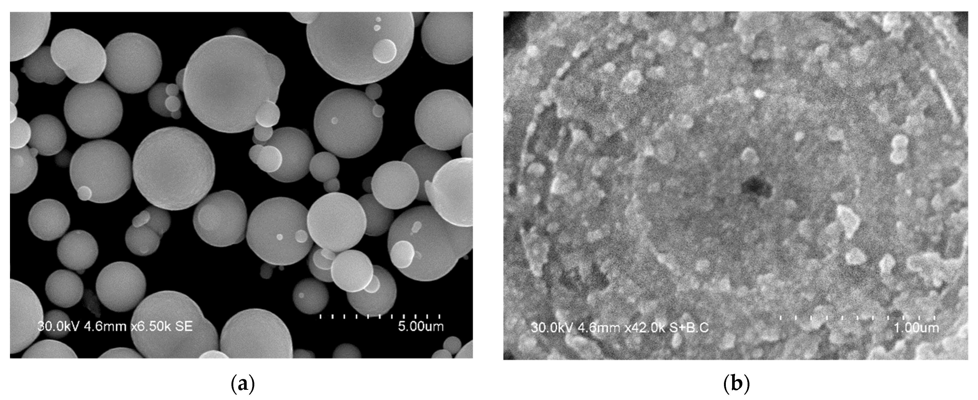
The particles of the iron powder used in the present work had a spherical shape (
Figure 1a). The structure of the particles was revealed by etching their polished cross-sections by a HNO
3-C
2H
5OH mixture. The multiple layers form an onion structure, each shell consisting of nanosized particles (
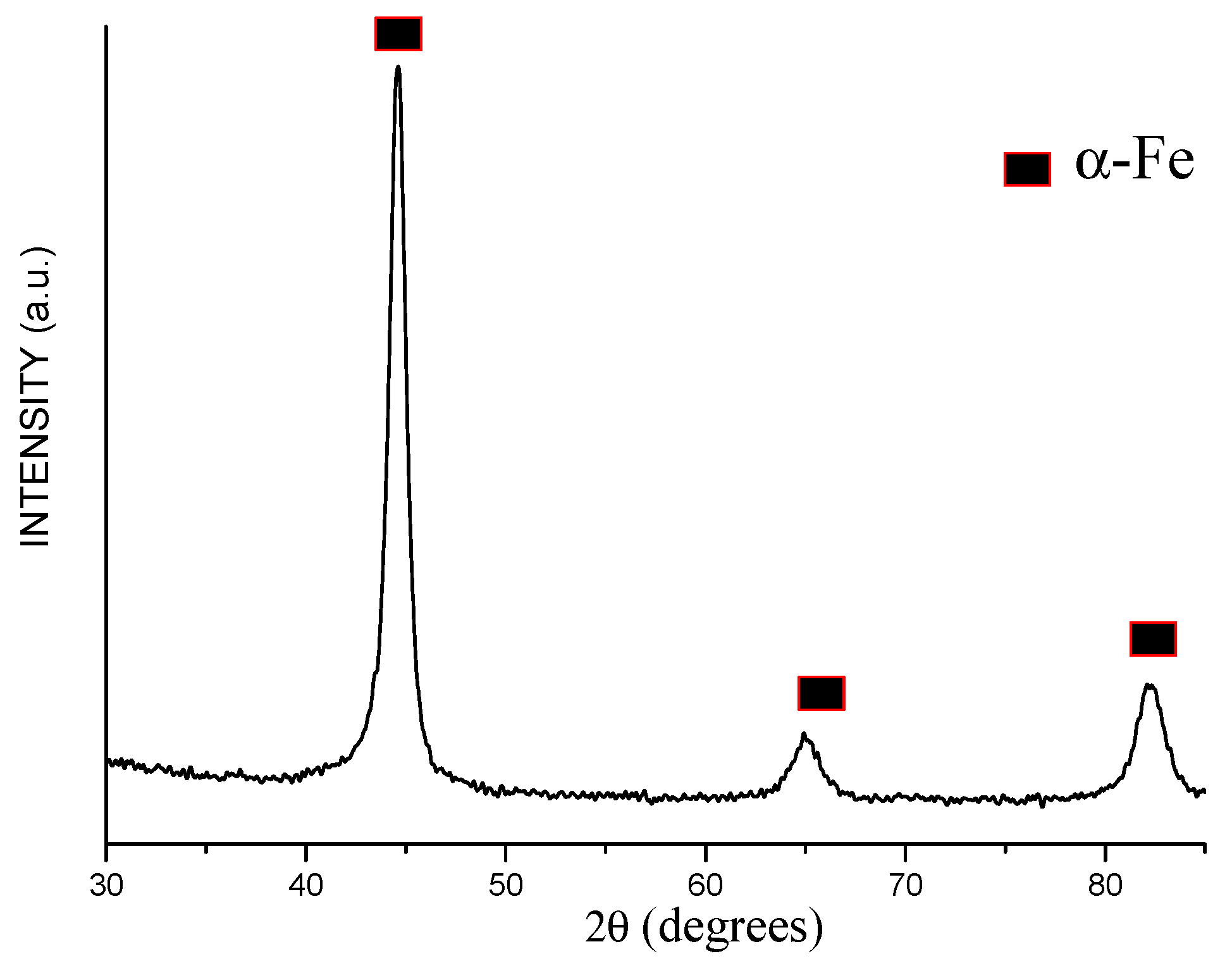
Figure 1b). The XRD peaks of the powder (
Figure 2) are those of body-centered cubic (bcc) iron (α-Fe). The peaks are significantly broadened. The crystallite size of iron was calculated to be 10 ± 1 nm. The lattice parameter of iron was determined to be 2.868 ± 0.001 Å, which is close to the lattice parameter of pure iron (PDF card 6-696).
The phase transformations in the Fe-Pd materials obtained in the present work (based on results of the XRD analysis) and the lattice parameters of the phases are presented in
Table 1.
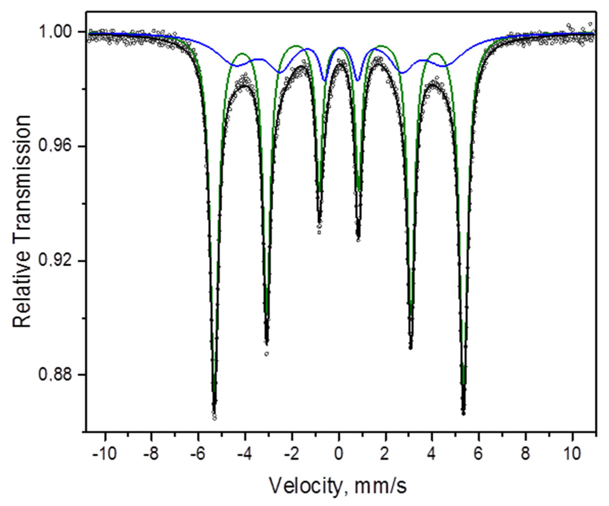
The Mössbauer spectrum of the carbonyl iron powder can be described as a superposition of two sextets (
Table 2,
Figure 3). The first sextet is due to the presence of α-Fe (
Figure 3, green line). The parameters of the second sextet (
Figure 3, blue line) suggest that it can originate from “disordered” α-Fe (the presence of multiple defects in the crystalline lattice of α-Fe), which agrees well with the results of XRD and microscopy investigations of the structure of this powder.
3.2. Formation of Fe@Pd Core–Shell Particles by Galvanic Replacement
In order to deposit palladium on the surface of iron particles, a galvanic replacement reaction was carried out. This reaction occurred upon treatment of the iron particles by PdCl
2 solution in HCl acid. The following scheme describes the chemical processes upon galvanic replacement:
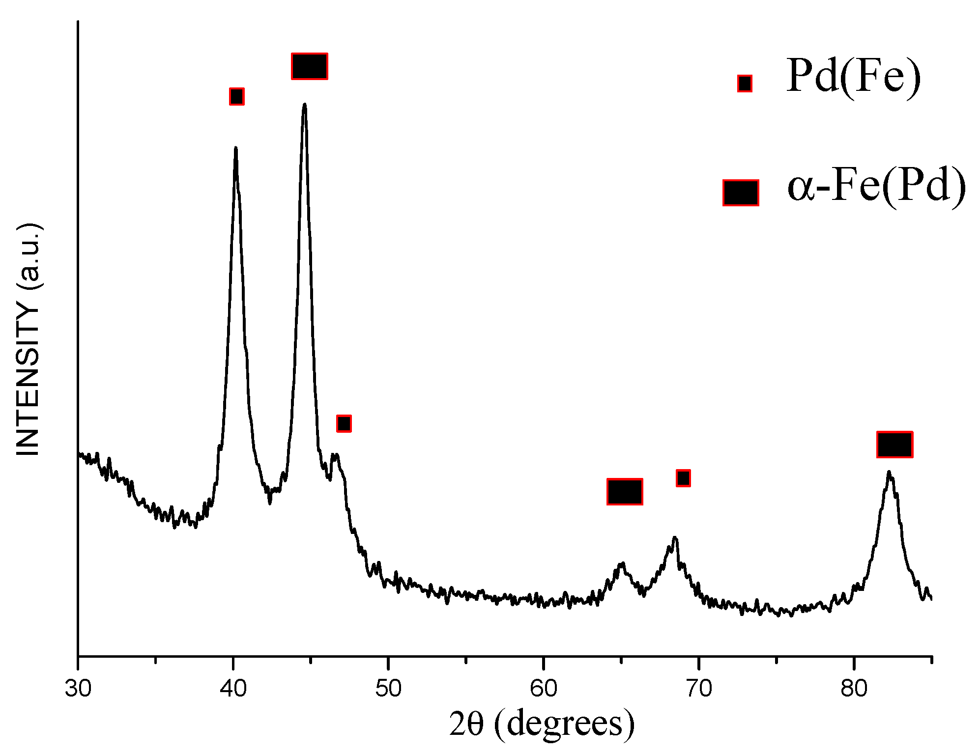
On the XRD pattern of the product of galvanic replacement, broadened reflections with positions close to those of metallic palladium (face-centered cubic (fcc) phase) are detected, along with reflections of α-Fe (
Figure 4). The lattice parameter of the fcc phase was calculated to be 3.879 ± 0.002 Å (
Table 1), which is lower than the lattice parameter of pure palladium (3.890 Å, PDF card 46-1043). This can be explained by the dissolution of iron in the palladium lattice (formation of Pd(Fe) solid solution) during the deposition of palladium on the iron surface (the atomic radius of iron is smaller than that of palladium). The crystallite size of the fcc was determined to be 7 ± 1 nm. The crystallite size of the bcc phase of the product of galvanic replacement was 11 ± 1 nm (did not change relative to the untreated iron powder). The lattice parameter of the bcc phase (2.873 ± 0.002 Å) was increased relative to pure iron (
Table 1).
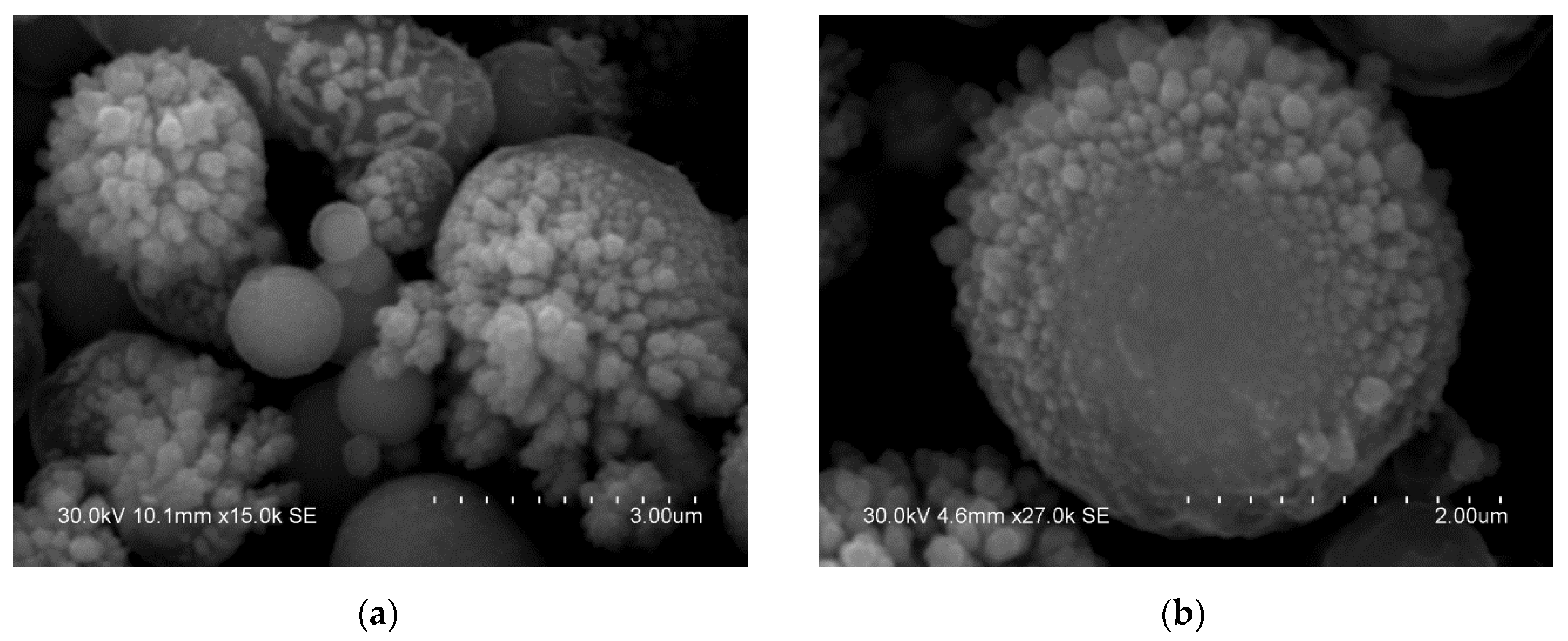
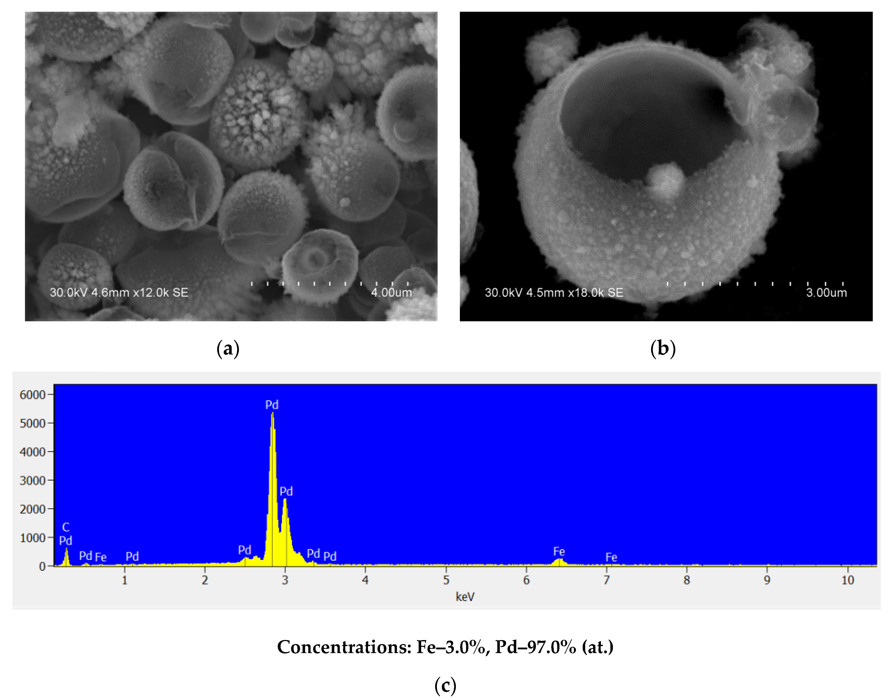
The electron microscopy images of the product of galvanic replacement show that a layer is formed on the surface of the iron particles (
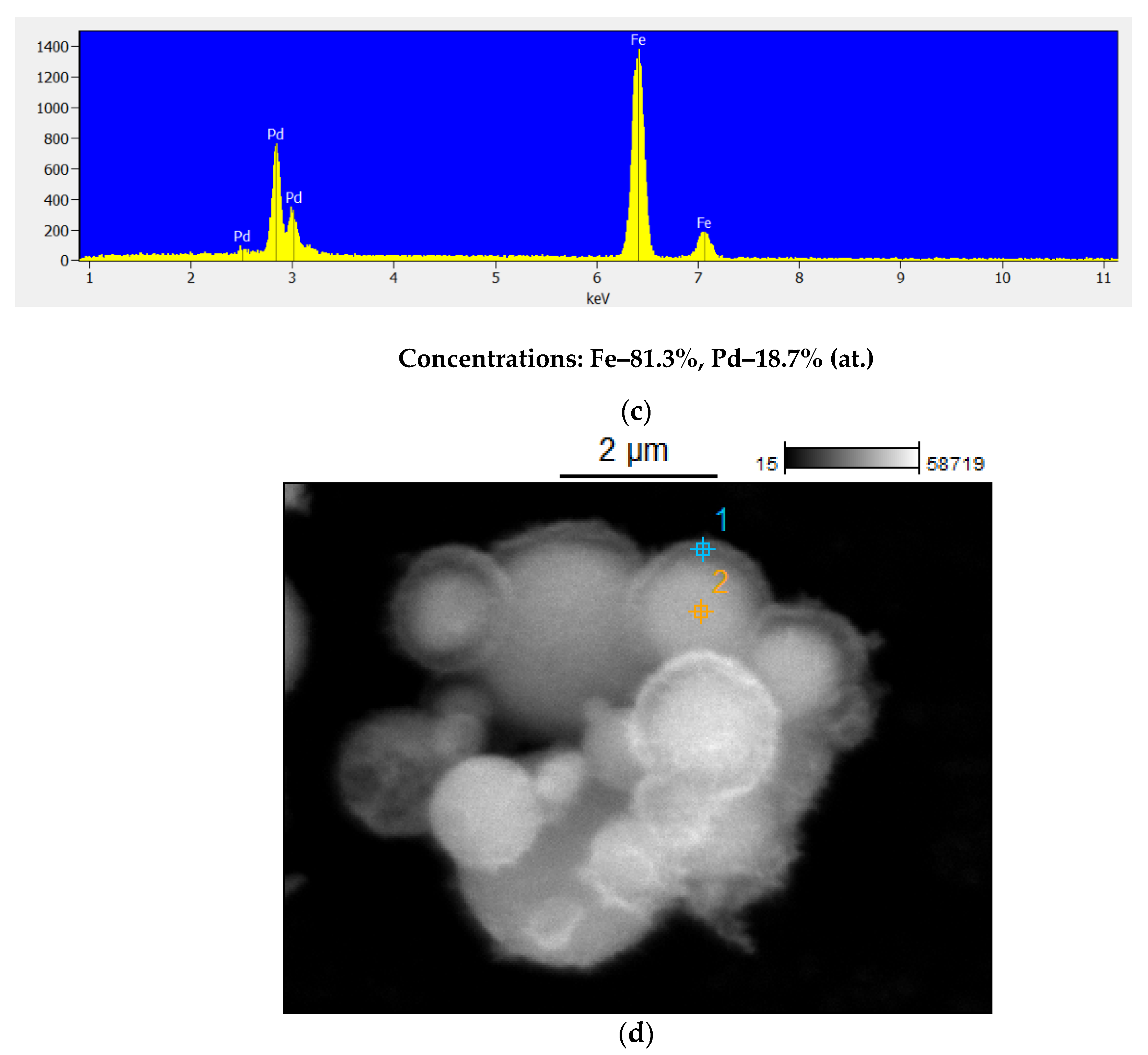
Figure 5a,b). This layer consists of separate submicron particles. The product of galvanic replacement is Fe@Pd core–shell particles, in which the core is Fe-based and the shell is Pd-based. It should be noted that some shells are not continuous and have orifices in them, which is typical for particles obtained by this method. The EDS analysis (
Figure 5c) shows that the Fe/Pd atomic ratio in the product of galvanic replacement is close to 4:1, which indicates a nearly full reduction of palladium ions present in the solution by metallic iron. In
Figure 5d, cross-sections of the core–shell particles are shown. The presence of shell is clearly visible in the image.
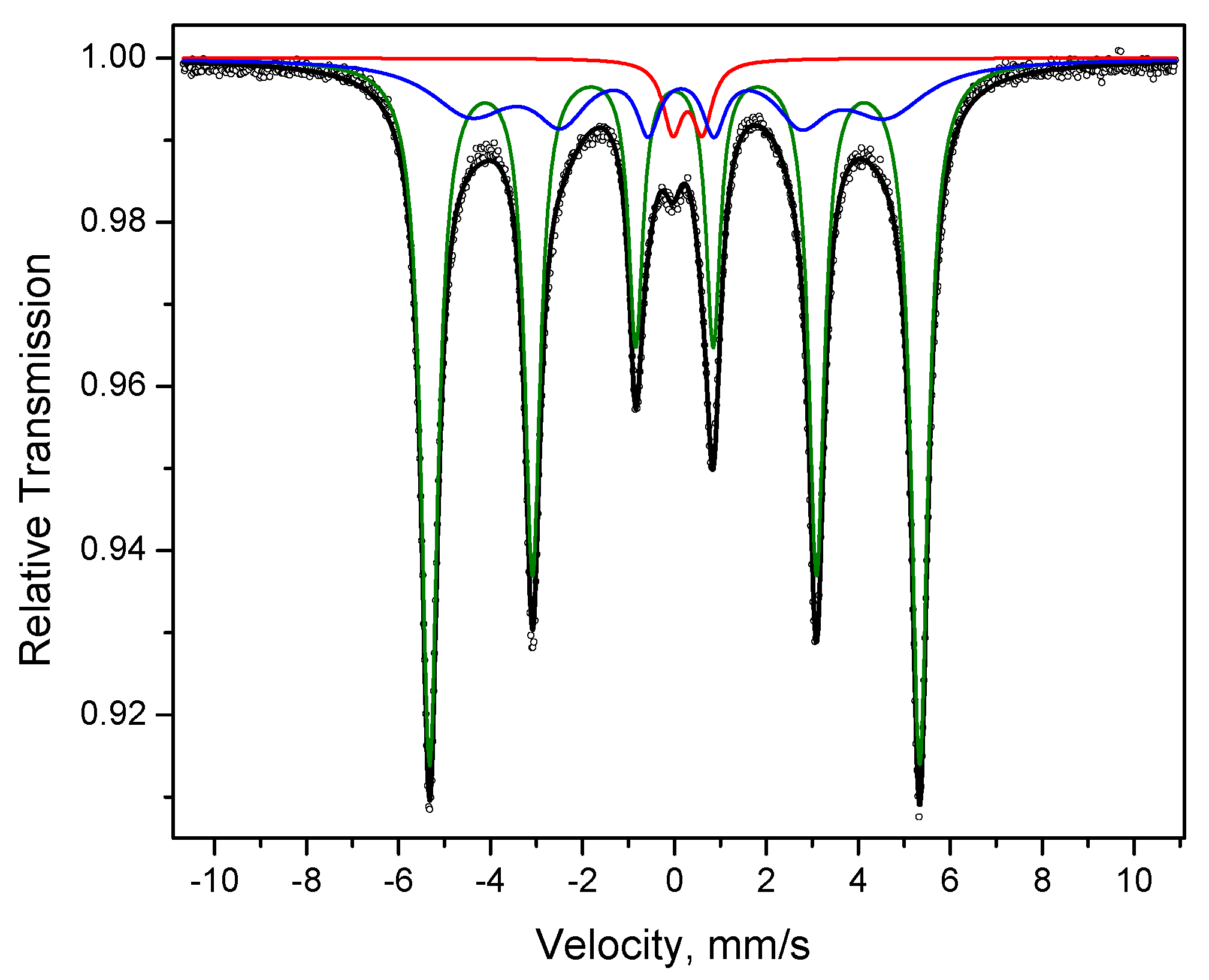
In the Mössbauer spectrum of the core–shell particles, two sextets are present corresponding to α-Fe (green line) and α-Fe with a “disordered” structure (blue line), as discussed in
Section 3.1 (
Figure 6). In addition, a doublet is present (red line), which can be related to the presence of Fe
3+. The presence of this doublet can be due to the formation of a small amount of the oxide phase during the preparation of the sample. A similar effect was earlier observed in ref. [
34].
3.3. Selective Dissolution of Iron from the Fe@Pd Core–Shell Particles: Formation of Hollow Palladium Particles
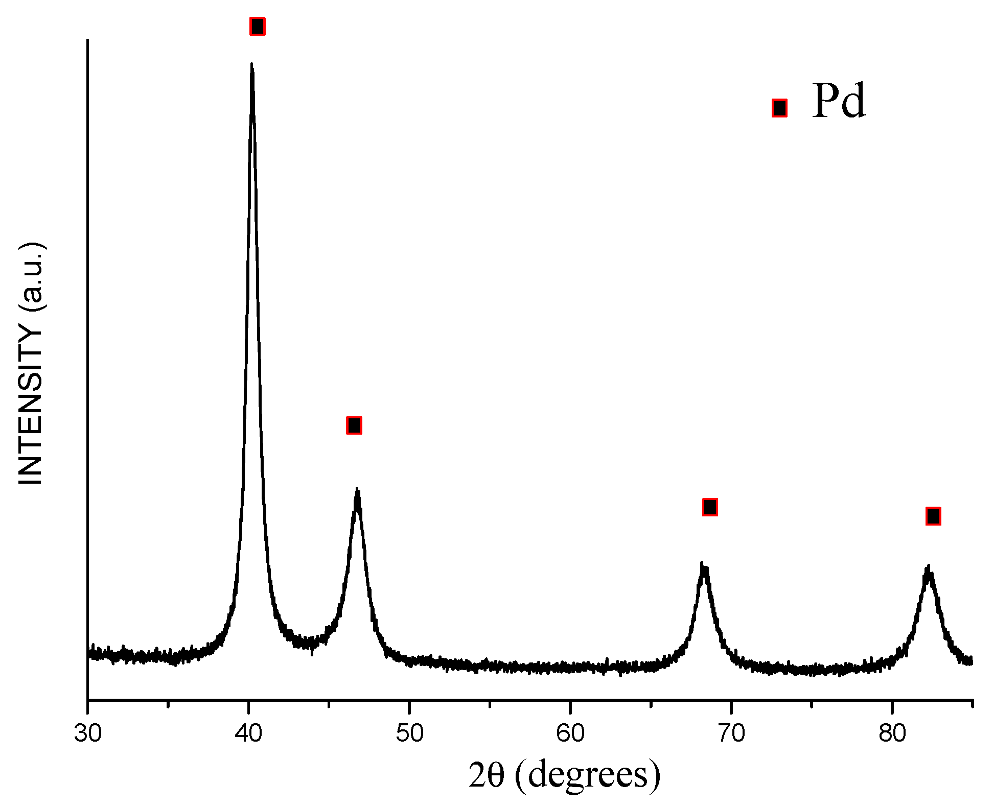
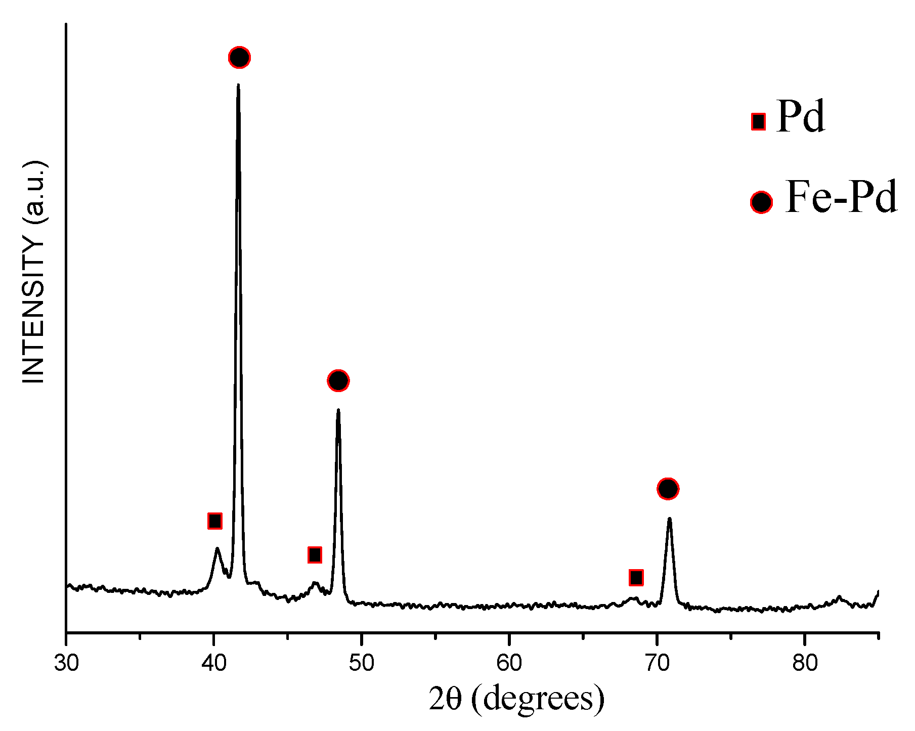
Upon treatment of the Fe@Pd core–shell particles by HCl solution, iron was selectively dissolved. On the XRD patterns of the product of acid treatment, only reflections of palladium are seen (
Figure 7). The crystallite size of the palladium is 11 ± 1 nm. The lattice parameter of palladium is 3.889 ± 0.001 Å, which is close to the lattice parameter of pure palladium.
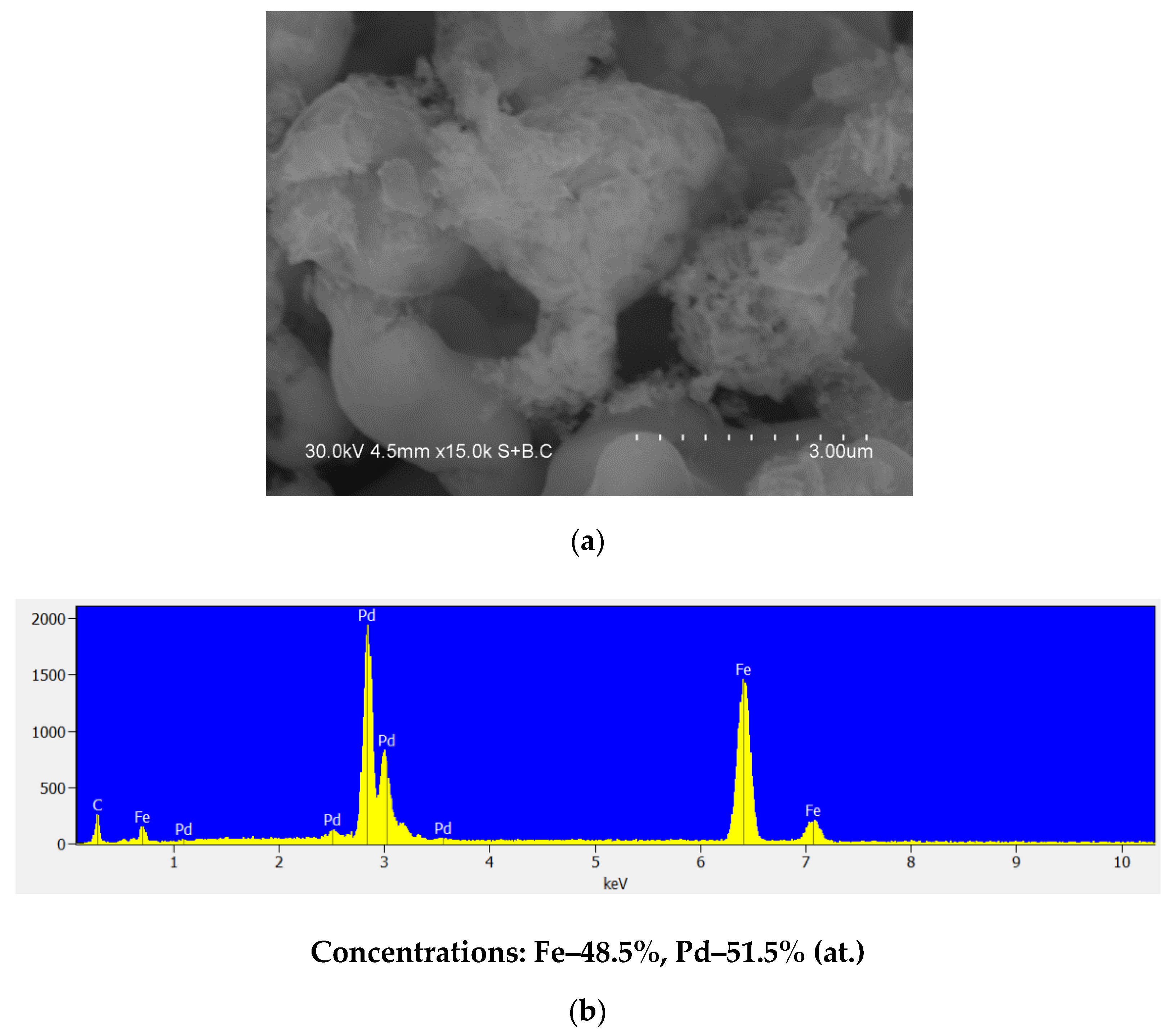
The electron microscopy images show that the acid treatment of the core–shell particles leads to the formation of hollow particles of palladium (
Figure 8a,b). While the lines of the iron phase are absent from the XRD profile of the hollow particles, the analysis conducted by EDS shows the presence of iron (
Figure 8c). The Fe/Pd atomic ratio in the shells was found to be equal to 1:32.
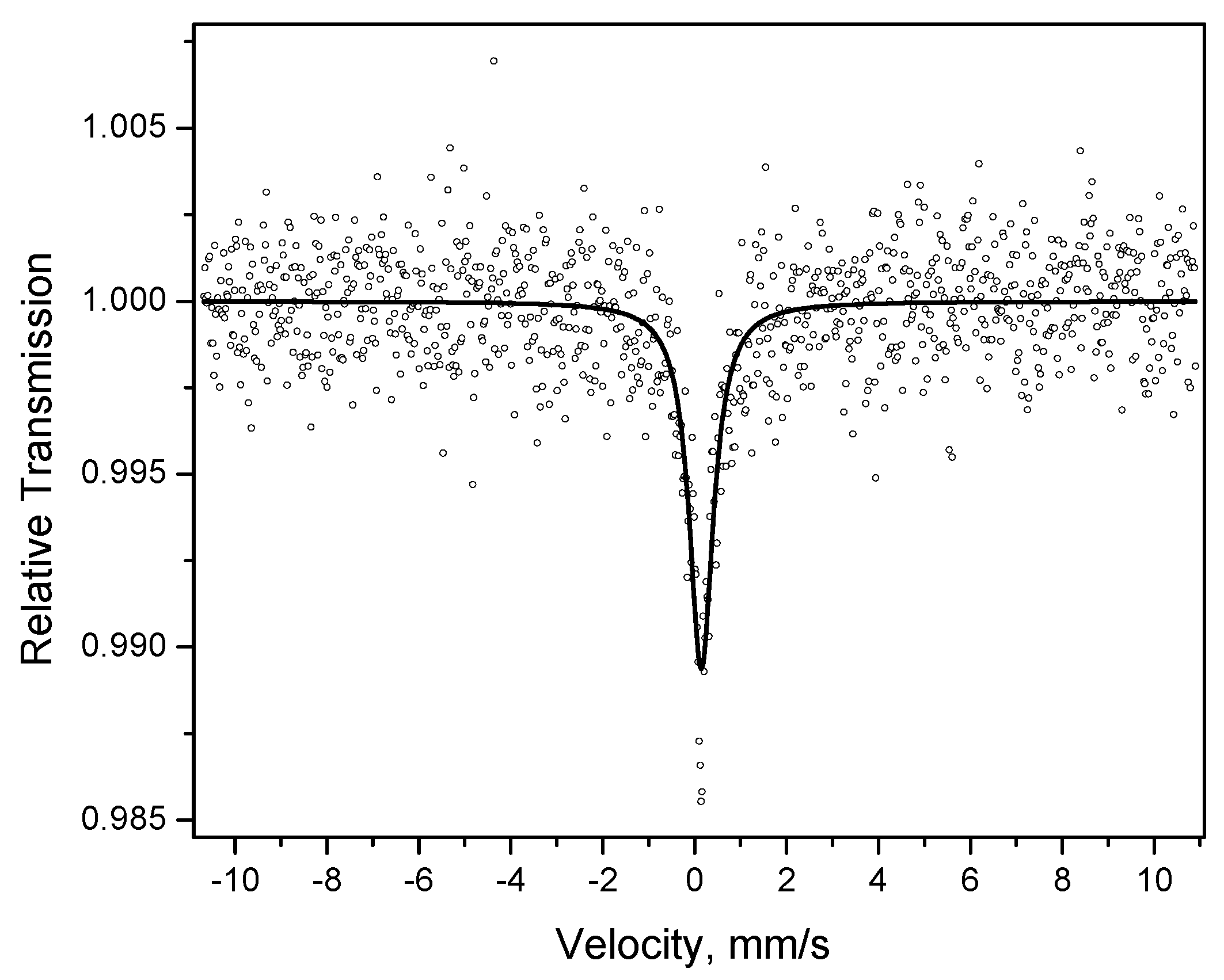
The Mössbauer spectrum of the hollow particles is a broad singlet with an isomer shift of 0.15 mm s
−1 (
Figure 9), which is close to the isomer shift of iron dissolved in palladium (0.17 mm s
−1) [
35]. This indicates the presence of iron dissolved in palladium (the formation of Pd(Fe) alloy hollow particles).
3.4. Phase and Structural Evolution of the Fe@Pd Particles upon Annealing
The Fe-Pd phase diagram is rather complex [
36,
37]. There exist two intermetallic compounds (FePd and FePd
3) in the system. Above 800 °C, the metals are fully mutually soluble. Below 200 °C, Fe
xPd
100−x solid solutions of fcc structure form at 0 < x < 10. When x > 70, solid solutions of bcc structure form.
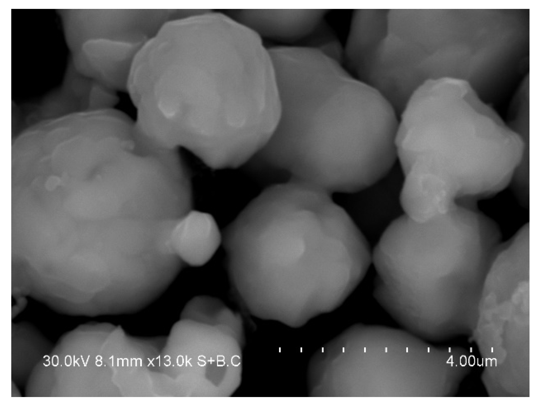
The electron microcopy investigations showed that the product of annealing of the core–shell Fe@Pd particles at 800 °C consists of dense particles 1–4 μm in size (
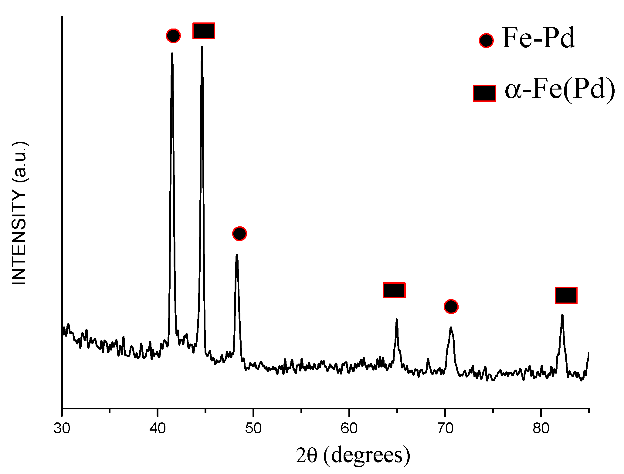
Figure 10). The XRD pattern of the annealed powder showed the peaks of a bcc phase and a fcc phase (
Figure 11). The latter shifted to higher angles relative to their positions on the pattern of the core–shell particles (
Figure 4). The crystallite size of the metals increased after annealing: the crystallite size of the bcc phase was 68 ± 18 nm, while that of the fcc phase was 64 ± 19 nm. The lattice parameter of the bcc phase was 2.875 ± 0.001 Å in the annealed powder. The calculated lattice parameter of the fcc phase was 3.773 ± 0.001 Å, which is smaller than the lattice parameter of metallic palladium (
Table 1). A significant reduction in the lattice parameter of the fcc phase can be explained by the formation of a Fe-Pd solid solution during annealing of the Fe@Pd core–shell particles. The concentration of palladium in this solid solution is ≈49 at %, as calculated using Vegard’s rule. The formation of a solid solution with a close lattice parameter was described in [
38] for a fcc structure of Fe
50Pd
50 composition. Thus, it can be concluded that annealing of the Fe@Pd core–shell particles activates diffusion and induces the formation of a Fe-rich fcc solid solution with a composition close to Fe
50Pd
50.
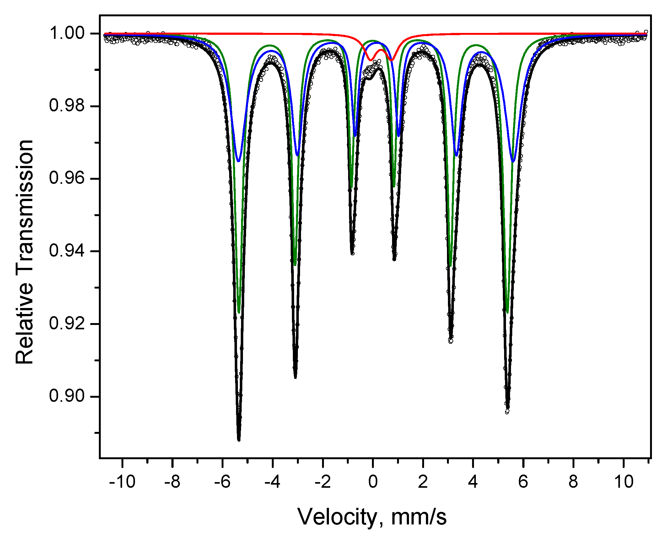
The Mössbauer spectrum of the alloy obtained by annealing of the Fe@Pd core–shell particles shows two sextets (
Figure 12). The parameters of one of them are close to those of α-Fe (green line), but the magnetic splitting is higher. The second sextet (blue line) has broadened lines, a greater isomer shift and even higher magnetic splitting. These characteristics suggest that the sextet is due to the presence of a Fe-rich Fe-Pd solid solution. In the spectrum, a doublet is present (red line), which can be related to the presence of Fe
3+ in a low concentration, as noted above.
3.5. Selective Dissolution of Iron from the Annealed Alloy
The treatment of the annealed powder in HCl solution led to the dissolution of iron from the bcc phase, as confirmed by the XRD analysis. No reflections of iron were detected (
Figure 13). After HCl treatment, the alloy was composed of a Fe-Pd solid solution with a lattice parameter of 3.773 ± 0.001 Å (major phase) and metallic palladium with crystallites of 10 ± 2 nm (minor phase). The fcc Fe-Pd solid solution formed during annealing remained stable during the acid treatment (
Table 1). The appearance of reflections of palladium is most likely due to the release of palladium upon the dissolution of iron from the bcc Fe(Pd) solid solution. The morphology of the particles can be seen in
Figure 14a. The overall composition of the system changes from the Fe/Pd atomic ratio of 4:1 before the acid treatment to 1:1 after the acid treatment (
Figure 14b). So, the acid treatment leads to the Pd enrichment of the system as a whole.
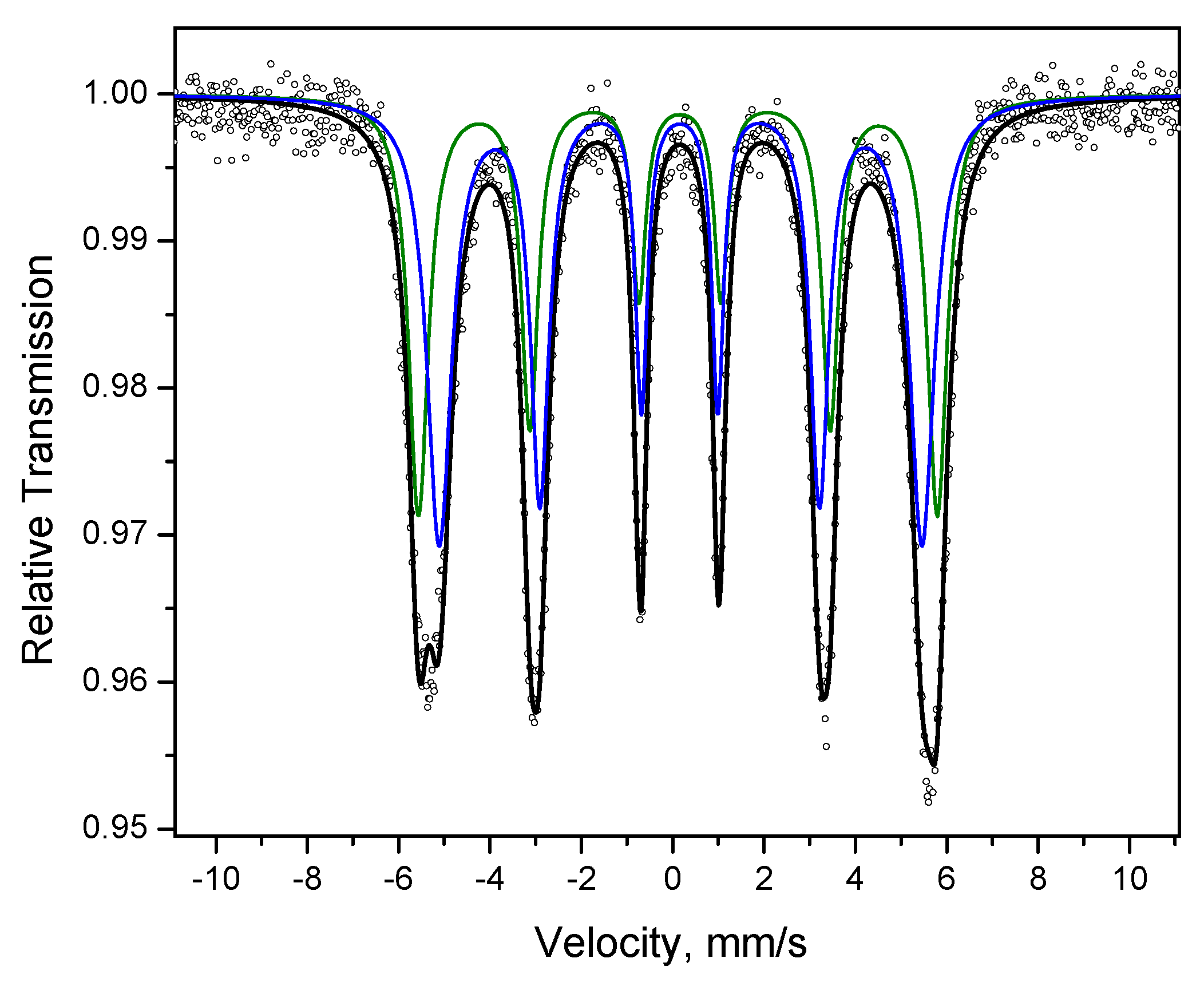
The Mössbauer spectrum of the powder after annealing and treatment in HCl solution (
Figure 15) shows two sextets with parameters characteristic of Fe-rich Fe-Pd solid solutions marked in
Table 2 as (I) and (II). This confirms that the solid solution was resistant to acid treatment and was preserved in the system. It should be noted that the acid treatment of the as-synthesized Fe@Pd core–shell particles and annealed powder produces different results. While it is possible to dissolve iron from the as-synthesized core-shell particles almost fully, the Fe-rich Fe-Pd solid solution formed upon annealing remains stable to the acid attack.
4. Summary
The morphological and structural features of Fe-Pd alloys formed by galvanic replacement, annealing and acid treatment have been studied. As galvanic replacement occurred, iron was replaced by palladium, which resulted in the formation of Fe@Pd core–shell microparticles. Based on results of XRD and Mössbauer spectroscopy, it was concluded that the Pd-based shells were a fcc Pd(Fe) solid solution. HCl acid treatment of the Fe@Pd core–shell particles allowed selectively dissolving iron from the cores and forming hollow Pd(Fe) particles. Upon annealing of the Fe@Pd core–shell particles, a Fe-rich Fe-Pd solid solution formed, which was confirmed by both XRD and Mössbauer spectroscopy. HCl treatment of the Fe-Pd alloy formed by annealing of the core–shell particles led to the selective dissolution of iron from the Fe-based phase (bcc Fe(Pd) solid solution), while the Fe-rich Fe-Pd fcc solid solution remained stable during the acid treatment. This work has shown than galvanic replacement and selective dissolution can be used for obtaining Fe-Pd alloys in the form of core–shell and hollow particles. Annealing and acid treatment can be applied to modify the phase composition and the ratio of metals in these alloys.
Author Contributions
Conceptualization, B.B.B.; methodology, B.B.B.; investigation, S.A.P., D.V.D. and A.V.U.; writing—original draft preparation, B.B.B. and S.A.P.; writing—review and editing, D.V.D.; supervision, B.B.B.; funding acquisition, B.B.B. All authors have read and agreed to the published version of the manuscript.
Funding
This work is supported by the Ministry of Science and Higher Education of the Russian Federation within State Assignment to ISSCM SB RAS, project #121032500065-5.
Conflicts of Interest
The authors declare no conflict of interest. The funders had no role in the design of the study; in the collection, analyses, or interpretation of data; in the writing of the manuscript, or in the decision to publish the results.
References
- Wang, Z.; Liu, P.; Han, J.; Cheng, C.; Ning, S.; Hirata, A.; Fujita, T.; Chen, M. Engineering the internal surfaces of three-dimensional nanoporous catalysts by surfactant-modified dealloying. Nat. Comm. 2017, 8, 1066. [Google Scholar] [CrossRef] [PubMed]
- Xu, Y.; Zhang, B. Recent advances in porous Pt-based nanostructures: Synthesis and electrochemical applications. Chem. Soc. Rev. 2014, 43, 2439–2450. [Google Scholar] [CrossRef] [PubMed]
- Qiu, H.J.; Gao, J.; Wen, Y.; Chiang, F.K.; Yao, A.; Wang, J.; Liu, X.; Du, P.; Fang, G. A general and scalable approach to produce nanoporous alloy nanowires with rugged ligaments for enhanced electrocatalysis. J. Mater. Chem. A 2018, 6, 12541–12550. [Google Scholar] [CrossRef]
- Lu, L.; Kang, J. Amperometric nonenzymatic sensing of glucose at very low working potential by using a nanoporous PdAuNi ternary alloy. Microchim. Acta 2018, 185, 111. [Google Scholar] [CrossRef]
- Su, L.; Gan, Y.X. Nanoporous Ag and Ag–Sn anodes for energy conversion in photochemical fuel cells. Nano Energy 2012, 1, 159–163. [Google Scholar] [CrossRef]
- Lu, L. Nanoporous noble metal-based alloys: A review on synthesis and applications to electrocatalysis and electrochemical sensing. Microchim. Acta 2019, 186, 664. [Google Scholar] [CrossRef]
- Lu, L.; Huang, X.; Dong, Y.; Huang, Y.; Pan, X.; Wang, X.; Feng, M.; Luo, Y.; Fang, D. Facile method for fabrication of self-supporting nanoporous gold electrodes via cyclic voltammetry in ethylene glycol, and their application to the electrooxidative determination of catechol. Microchim. Acta 2015, 182, 1509–1517. [Google Scholar] [CrossRef]
- Weremfo, A.; Fong, S.T.C.; Khan, A.; Hibbert, D.B.; Zhao, C. Electrochemically roughened nanoporous platinum electrodes for non-enzymatic glucose sensors. Electrochim. Acta 2017, 231, 20–26. [Google Scholar] [CrossRef]
- Qiu, H.J.; Xu, H.T.; Li, X.; Wang, J.Q.; Wang, Y. Core–shell-structured nanoporous PtCu with high cu content and enhanced catalytic performance. J. Mater. Chem. A 2015, 3, 7939–7944. [Google Scholar] [CrossRef]
- Zhao, S.; Gorte, R.J. The activity of Fe-Pd alloys for the water-gas shift reaction. Catal. Lett. 2004, 92, 75–80. [Google Scholar] [CrossRef] [Green Version]
- Riva, J.S.; Juárez, A.V.; Urreta, S.E.; Yudi, L.M. Catalytic properties of Fe–Pd ferromagnetic nanowires at liquid/liquid interfaces. Electrochim. Acta 2019, 298, 379–388. [Google Scholar] [CrossRef]
- Kock, I.; Hamann, S.; Brunken, H.; Edler, T.; Mayr, S.G.; Ludwig, A. Development and characterization of Fe70Pd30 ferromagnetic shape memory splats. Intermetallics 2010, 18, 877–882. [Google Scholar] [CrossRef]
- Cialone, M.; Celegato, F.; Scaglione, F.; Barrera, G.; Deepti, R.; Coisson, M.; Tiberto, P.; Rizzi, P. Multifunctional ferromagnetic and SERS-active nanoporous FePd alloy synthesized via dealloying. Appl. Surf. Sci. 2021, 543, 148759. [Google Scholar] [CrossRef]
- Bryden, K.J. Pulsed Electrodeposition synthesis and hydrogen absorption properties of nanostructured palladium-iron alloy films. J. Electrochem. Soc. 1998, 145, 3339. [Google Scholar] [CrossRef]
- Jasen, P.V.; Gonzalez, E.A.; Castellani, N.J.; Juan, A. Theoretical study of hydrogen adsorption on FePd face-centered cubic alloy surfaces. Phys. Rev. B 2005, 71, 235422. [Google Scholar] [CrossRef]
- Najdovski, I.; O’Mullane, A.P.; Bhargava, S.K. Electrochemical properties of galvanically replaced iron nanocubes with gold and palladium. Electrochem. Comm. 2010, 12, 1535–1538. [Google Scholar] [CrossRef]
- Benhamoud, A.; Kharmouche, A. Synthesis, structural, and magnetic properties of Fe100−xPdx thin films. J. Supercond. Nov. Magn. 2020, 33, 1521–1526. [Google Scholar] [CrossRef]
- Shao, Z.; An, L.; Li, Z.; Huang, Y.; Hu, Y.; Ren, S.; Li, R. Eutectic crystallized FePd nanoparticles for liquid metal magnet. Chem. Commun. 2020, 56, 6555. [Google Scholar] [CrossRef]
- Soundararaj, A.; Mohanty, J. Magnetic properties of electrodeposited FePd alloy thin films. AIP Conf. Proc. 2017, 1832, 080066. [Google Scholar]
- Barrera, G.; Scaglione, F.; Cialone, M.; Celegato, F.; Coïsson, M.; Rizzi, P.; Tiberto, P. Structural and magnetic properties of FePd thin film synthesized by electrodeposition method. Materials 2020, 13, 1454. [Google Scholar] [CrossRef] [Green Version]
- Wang, J.; Wang, Z.; Zhao, D.; Xu, C. Facile fabrication of nanoporous PdFe alloy for nonenzymatic electrochemical sensing of hydrogen peroxide and glucose. Anal. Chim. Acta 2014, 832, 34–43. [Google Scholar] [CrossRef]
- Barrera, G.; Celegato, F.; Cialone, M.; Coïsson, M.; Rizzi, P.; Tiberto, P. Structural, wetting and magnetic properties of sputtered Fe70Pd30 thin film with nanostructured surface induced by dealloying process. Nanomaterials 2021, 11, 282. [Google Scholar] [CrossRef] [PubMed]
- Kobayashi, Y.; Yoshida, H.; Ahn, S.; Chang, G.; Oyama, M. Palladium deposition on nickel wire electrodes by a galvanic replacement reaction. ACS Appl. Energy Mater. 2019, 2, 2337–2343. [Google Scholar] [CrossRef]
- Zhou, Y.; Du, C.; Han, G.; Gao, Y.; Yin, G. Ultra-low Pt decorated PdFe alloy nanoparticles for formic acid electro-oxidation. Electrochim. Acta 2016, 217, 203–209. [Google Scholar] [CrossRef]
- Fu, Q.; Meng, Y.; Fang, Z.; Hu, Q.; Xu, L.; Gao, W.; Huang, X.; Xue, Q.; Sun, Y.; Lu, F. Boron nitride nanosheet-anchored Pd−Fe core−shell nanoparticles as highly efficient catalysts for Suzuki−Miyaura coupling reactions. ACS Appl. Mater. Interf. 2017, 9, 2469–2476. [Google Scholar] [CrossRef] [PubMed]
- Hou, Y.; Kondoh, H.; Kogure, T.; Ohta, T. Preparation and characterization of monodisperse FePd nanoparticles. Chem. Mater. 2004, 16, 5149–5152. [Google Scholar] [CrossRef]
- Russell, A.D.; Whittell, G.R.; Haddow, M.F.; Manners, I. Facile formation of FePd nanoparticles from single-source ferrocenophane precursors. Organometallics 2014, 33, 5349–5357. [Google Scholar] [CrossRef]
- Guo, X.; Brault, P.; Zhi, G.; Caillard, A.; Jin, G.; Guo, X. Structural evolution of plasma-sputtered core-shell nanoparticles for catalytic combustion of methane. J. Phys. Chem. C 2011, 115, 24164–24171. [Google Scholar] [CrossRef] [Green Version]
- Xia, X.H.; Wang, Y.; Ruditskiy, A.; Xia, Y.N. 25th anniversary article: Galvanic replacement: A simple and versatile route to hollow nanostructures with tunable and well-controlled properties. Adv. Mater. 2013, 25, 6313–6333. [Google Scholar] [CrossRef]
- Ali, R.; Ali, F.; Zahoor, A.; Shahid, R.N.; Tariq, N.H.; He, T.; Shahzad, M.; Asghar, Z.; Shah, A.; Mahmood, A.; et al. Effect of sintering path on the microstructural and mechanical behavior of aluminum matrix composite reinforced with pre-synthesized Al/Cu core-shell particles. J. Alloys Compd. 2021, 889, 161531. [Google Scholar] [CrossRef]
- Wang, C.; Xu, W.; Qin, Z.; Mintova, S. Spontaneous galvanic deposition of nanoporous Pd on microfibrous-structured Al-fibers for CO oxidative coupling to dimethyl oxalate. Catal. Comm. 2019, 119, 39–41. [Google Scholar] [CrossRef]
- Bokhonov, B.B.; Dudina, D.V. Preparation of porous materials by Spark Plasma Sintering: Peculiarities of alloy formation during consolidation of Fe@Pt core-shell and hollow Pt(Fe) particles. J. Alloys Compd. 2017, 707, 233–237. [Google Scholar] [CrossRef]
- Bokhonov, B.B.; Dudina, D.V. Preparation of nanoporous gold particles on diamond facets via galvanic replacement and dealloying. Diam. Relat. Mater. 2022, 123, 108860. [Google Scholar] [CrossRef]
- Semenova, E.; Vorobyova, S.; Fedotova, J.; Bayev, V. Iron-palladium composite nanoparticles. In Proceedings of the International Conference Nanomeeting: Physics, Chemistry and Applications of Nanostructures, Minsk, Belarus, 28–31 May 2013; pp. 289–292. [Google Scholar]
- Stevens, J.G. Isomer shift reference scales. Hyperfine Interact. 1983, 13, 221–236. [Google Scholar] [CrossRef]
- Massalsky, T.B. Binary Alloys Phase Diagrams; ASM International: Materials Park, OH, USA, 1986. [Google Scholar]
- Villars, P.; Calvert, L.D. Pearsosn’s Handbook of Crystallographic Data for Intermetallic Phases, 2nd ed.; ASM International: Materials Park, OH, USA, 1991. [Google Scholar]
- Burzo, E.; Vlaic, P. Magnetic properties of iron-palladium solid solutions and compounds. J. Optoelectr. Adv. Mater. 2010, 12, 1869–1878. [Google Scholar]
Figure 1.
Morphology (a) and internal structure (b) of the carbonyl iron particles.
Figure 1.
Morphology (a) and internal structure (b) of the carbonyl iron particles.
Figure 2.
X-ray diffraction (XRD) pattern of the carbonyl iron powder.
Figure 2.
X-ray diffraction (XRD) pattern of the carbonyl iron powder.
Figure 3.
Mössbauer spectrum of the carbonyl iron powder: dots—experimental data, black line—spectrum represented as a superposition of two sextets (green and blue lines).
Figure 3.
Mössbauer spectrum of the carbonyl iron powder: dots—experimental data, black line—spectrum represented as a superposition of two sextets (green and blue lines).
Figure 4.
XRD pattern of the Fe@Pd core–shell particles obtained by galvanic replacement reaction.
Figure 4.
XRD pattern of the Fe@Pd core–shell particles obtained by galvanic replacement reaction.
Figure 5.
(a,b) Morphology of the Fe@Pd core–shell particles obtained by galvanic replacement reaction, different magnifications, (c) energy-dispersive spectroscopy (EDS) of the Fe@Pd core–shell particles obtained by galvanic replacement reaction, (d) cross-section of the core–shell particles (concentration of Pd in point 1 is higher than in point 2, as determined by EDS).
Figure 6.
Mössbauer spectrum of the Fe@Pd core–shell particles obtained by galvanic replacement reaction: dots—experimental data, black line—spectrum represented as a superposition of two sextets (green and blue lines) and a doublet (red line).
Figure 6.
Mössbauer spectrum of the Fe@Pd core–shell particles obtained by galvanic replacement reaction: dots—experimental data, black line—spectrum represented as a superposition of two sextets (green and blue lines) and a doublet (red line).
Figure 7.
XRD pattern of the product of acid treatment of Fe@Pd core–shell particles (hollow particles of a Pd-based alloy).
Figure 7.
XRD pattern of the product of acid treatment of Fe@Pd core–shell particles (hollow particles of a Pd-based alloy).
Figure 8.
(a,b) Morphology of the product of acid treatment of Fe@Pd core–shell particles (hollow particles), different magnifications, (c) EDS of the product of acid treatment of Fe@Pd core–shell particles (hollow particles of the Pd-based alloy).
Figure 8.
(a,b) Morphology of the product of acid treatment of Fe@Pd core–shell particles (hollow particles), different magnifications, (c) EDS of the product of acid treatment of Fe@Pd core–shell particles (hollow particles of the Pd-based alloy).
Figure 9.
Mössbauer spectrum of the product of acid treatment of Fe@Pd core–shell particles (hollow particles): dots—experimental data, black line—spectrum (singlet).
Figure 9.
Mössbauer spectrum of the product of acid treatment of Fe@Pd core–shell particles (hollow particles): dots—experimental data, black line—spectrum (singlet).
Figure 10.
Morphology of the powder alloy obtained by annealing of the Fe@Pd core–shell particles.
Figure 10.
Morphology of the powder alloy obtained by annealing of the Fe@Pd core–shell particles.
Figure 11.
XRD pattern of the powder alloy obtained by annealing of the Fe@Pd core–shell particles (Fe-Pd is a Fe-rich solid solution).
Figure 11.
XRD pattern of the powder alloy obtained by annealing of the Fe@Pd core–shell particles (Fe-Pd is a Fe-rich solid solution).
Figure 12.
Mössbauer spectrum of the powder alloy obtained by annealing of the Fe@Pd core–shell particles: dots—experimental data, black line—spectrum represented as a superposition of two sextets (green and blue lines) and a doublet (red line).
Figure 12.
Mössbauer spectrum of the powder alloy obtained by annealing of the Fe@Pd core–shell particles: dots—experimental data, black line—spectrum represented as a superposition of two sextets (green and blue lines) and a doublet (red line).
Figure 13.
XRD pattern of the annealed powder treated in HCl solution (Fe-Pd is a Fe-rich solid solution).
Figure 13.
XRD pattern of the annealed powder treated in HCl solution (Fe-Pd is a Fe-rich solid solution).
Figure 14.
Morphology of the annealed powder treated in HCl solution (a), EDS of the annealed powder treated in HCl solution (b).
Figure 14.
Morphology of the annealed powder treated in HCl solution (a), EDS of the annealed powder treated in HCl solution (b).
Figure 15.
Mössbauer spectrum of the annealed powder treated in HCl solution: dots—experimental data, black line—spectrum represented as a superposition of two sextets (green and blue lines).
Figure 15.
Mössbauer spectrum of the annealed powder treated in HCl solution: dots—experimental data, black line—spectrum represented as a superposition of two sextets (green and blue lines).
Table 1.
Phases (as determined by X-ray diffraction) and their lattice parameters (Å) of the Fe-Pd alloys described in the present work. The lattice parameter of pure metallic palladium is 3.890 Å, pure metallic bcc iron—2.867 Å (bcc—body-centered cubic, fcc—face-centered cubic). Atomic radius of iron is 126 pm. Atomic radius of palladium is 137 pm.
| Powder | Bcc Fe | Bcc Fe(Pd) Solid Solution | Fcc Pd | Fcc Pd(Fe)/
Fcc Fe-Rich Fe-Pd Solid Solution * |
|---|
| Fe powder | +
2.868 ± 0.001 | - | - | - |
| Fe@Pd core–shell particles | - | +
2.873 ± 0.002 | - | +
3.879 ± 0.002 |
| Hollow Pd-based particles | - | - | +
3.889 ± 0.001 | - |
| Product of annealing of Fe@Pd at 800 °C | - | 2.875 ± 0.001 | - | (#) 3.773 ± 0.001 |
| Product of annealing of Fe@Pd at 800 °C after acid treatment | - | - | +
3.889 ± 0.001 | +
(#) 3.773 ± 0.001 |
Table 2.
Parameters of the Mössbauer spectra of the Fe-Pd powder alloys *.
Table 2.
Parameters of the Mössbauer spectra of the Fe-Pd powder alloys *.
| Powder | State of Iron | Area Fraction, % | δ, mm s−1 | Bhf, T | Δ, mm s−1 |
|---|
| Fe powder | α-Fe | 71 | 0.005 | 33.22 | 0.001 |
| disordered α-Fe | 29 | 0.086 | 27.50 | −0.02 |
Fe@Pd
core–shell particles | α-Fe | 71 | 0.005 | 33.23 | 0.002 |
| Fe3+ | 4 | 0.287 | - | 0.64 |
| disordered α-Fe | 25 | 0.116 | 28.14 | −0.03 |
| Hollow Pd-based particles | Pd(Fe) | 100 | 0.154 | - | - |
| Product of annealing of Fe@Pd at 800 °C | α-Fe | 51 | 0.001 | 33.38 | 0.007 |
| Fe-Pd solid solution | 46 | 0.135 | 34.15 | −0.02 |
| Fe3+ | 3 | 0.323 | - | 0.84 |
| Product of annealing of Fe@Pd at 800 °C after acid treatment | Fe-Pd solid solution (I) | 43 | 0.138 | 35.40 | −0.02 |
| Fe-Pd solid solution (II) | 57 | 0.164 | 32.94 | 0.01 |
| Publisher’s Note: MDPI stays neutral with regard to jurisdictional claims in published maps and institutional affiliations. |
© 2022 by the authors. Licensee MDPI, Basel, Switzerland. This article is an open access article distributed under the terms and conditions of the Creative Commons Attribution (CC BY) license (https://creativecommons.org/licenses/by/4.0/).


