Article

A New Wire Electrode for Improving the Machining Characteristics of High-Volume Fraction SiCp/Al Composite in WEDM

1
State Key Laboratory of High Performance Complex Manufacturing, College of Mechanical and Electrical Engineering, Central South University, Changsha 410083, China
2
Shenzhen Research Institute of Central South University, Shenzhen 518057, China
3
Guangdong Provincial Key Laboratory of Manufacturing Equipment Digitization, Guangdong HUST Industrial Technology Research Institute, Dongguan 523429, China
*
Author to whom correspondence should be addressed.
Submission received: 3 May 2022 / Revised: 22 May 2022 / Accepted: 29 May 2022 / Published: 9 June 2022
(This article belongs to the Special Issue Non-conventional Machining of Hard Materials)

Abstract

:
In wire electrical discharge machining, due to the random distribution of the insulating SiC particles, frequent wire rupture, low machining efficiency and surface quality when the common brass wire electrode (BWE) is used to process high-volume content SiCp/Al composite often appears. To address this issue, this paper proposes a new preparation method of zinc coating and surface microstructure on wire electrodes (ZCSMWE). The preparation process of ZCSMWE includes casting, coating, annealing and plastic processing. The experimental results show that, compared with BWE, ZCSMWE can increase material removal rate (MRR) by 16.67%, reduce surface roughness (Ra) by 21.18% and reduce wire rupture under the same discharge parameters. The analysis of workpiece surface topography shows that ZCSMWE can significantly decrease the recast layer and microcrack on the machined surface. The improvement mechanism of ZCSMWE main includes: The low work function zinc can promote the forming of the discharge channel. The vaporization of low boiling temperature zinc can reduce the temperature of the discharge gap and promote the ejecting of workpiece material. In addition, the surface microstructure on ZCSMWE can make the discharge spark more uniformly distributed and increase the proportion of the effective discharge, which contributes to making the discharge crater on the workpiece and wire electrode shallower and more uniform. The surface microstructure on ZCSMWE can also effectively improve the dielectric circulation, which can promote discharge debris to be expelled out and reduce the temperature in the discharge gap. Then, the wire rupture and microcracks on the workpiece surface can be reduced.

1. Introduction

A particle reinforced metal matrix composite (PR-MMC), such as SiCp/Al, possesses excellent comprehensive mechanical properties including high specified strength [1,2,3], outstanding thermal performance [4,5] and enhanced abrasion resistance [6,7]. Thus, SiCp/Al is widely employed in various fields, such as aerospace [8,9], the healthcare industry and precise molds [10,11]. However, traditional methods (such as milling and turning) employed in the fabrication of SiCp/Al workpieces require special-made and expensive tools (diamond tools) due to their high hardness and brittleness [12], whereas the contact machining would inevitably damage the PR-MMC surface.
WEDM is regarded as a non-contact processing method derived from EDM; therefore, its processing principle is quite similar to that of EDM [13,14,15]. In addition, the conductive workpiece applied with WEDM will be struck by electricity escaping from the wire electrode due to the fierce electric field [16,17,18], generating a large amount of heat, melting or the vaporizing material. Under this direction, wire electrical discharge machining (WEDM) is considered an effective way to process SiCp/Al [19]. Satishkumar et al. [20] focused on the influence of the parameters and the volume fraction of SiCp/Al on the machining performance in WEDM. Under this perspective, an L9 orthogonal array experiment was designed and the analysis of the extracted variance and response graphs was applied to analyze the results. It was pointed out that by increasing the volume fraction of the SiC particles, the MRR value would decrease and the Ra value would increase. Additionally, the recast layer would weaken the impact of the surface texture of wire on the erosion of the Al matrix. Yang Wenshu et al. [21] analyzed the process mechanism of the Al2024-65 vol.% SiC, where the processed surface was characterized by SEM, XRD, XPS, and TEM imaging. It was found that SiC particles were cut and the main process mechanism of the SiCp/Al mainly was combined by the melt of Al and the decomposition of SiC. In addition, the high melting point alloys of the wire electrode can strengthen the machining performance of the high-volume fraction SiCp/Al in WEDM. Wang Zhenlong et al. [22] applied micro-WEDM to process the medium volume SiCp/Al and mentioned that the recast layer could damage the machining surface. Furthermore, it was illustrated that the process mechanism of the ceramic particles was spalling and the recast layer could be thicker when the multi-cutting was applied. Murari V.P.G. et al. [23] used WEDM to cut low conductive Al(75%)-SiC(10%)-TiC(10%) composite. It was pointed out that the proposed oil + wax + paraffin dielectric medium could effectively improve the machining characteristics of MMC composite. Kumar H. [24] adopted WEDM to cut Al/10 wt.% SiC-MMC. A quadratic regression model for surface roughness (Ra) was obtained to optimize the machining parameters. The aforementioned studies demonstrated that the enrichment of the applied process mechanism of PR-MMC was successfully improved by the PR-MMC machining performance in WEDM. Nevertheless, the volume fraction of SiC particles in the workpieces in the previously reported studies was relatively low, while the high-volume fraction SiC/Al was more difficult to achieve stable processing due to frequent wire rupture.
Apart from the discharge processing parameters, the wire electrode is recognized as a conspicuous factor affecting the machining performance of WEDM [25,26,27,28]. It is interesting to notice that brass was the most applied wire electrode material during industrial production [29]. To further improve the machining characteristics of WEDM, a sizable amount of improvement project research has come up; surface coated wire is one of them. More specifically, Soutrik et al. [30] processed a titanium hybrid composite reinforced with boron powder via employing a zinc-coated wire electrode (ZCWE) in WEDM. A new optimization algorithm based on the desirable grey relational analysis was proposed to optimize the machining parameters. It was demonstrated that this new optimization algorithm can improve the machining performance more effectively. Saha et al. [31] studied the application of a nanostructured hardfacing material in WEDM. The various processing properties were characterized and the experimental parameters were optimized. The ZCWE was observed as being more suitable for processing nanostructured hardfacing material than the BWE due to its higher processing rate and lower surface roughness. Manjajah et al. [32] compared the machining performance between ZCWE and BWE in WEDM when processing a shape memory alloy. The MRR, surface roughness and surface morphology were systematically characterized and investigated. It was demonstrated that the ZCWE obtained higher MRR, better surface quality and less surface crack density. In addition, a small impact on the chemical composition of the surface was found. Sharma et al. [33] compared the BWE and ZCWE machining Inconel 706. The authors observed that under the same processing parameters, the brass wire could improve the surface quality; the surface topography is relatively smooth and the recast layer is thinner. Whereas ZCWE can increase the machining efficiency and reduce recast layer, but also lead to higher surface roughness. Radhakrishnan et al. [34] made the wire electrode vibrate at a different frequency value and investigated the white layer and surface roughness. The white layer and the surface roughness of the workpiece were both improved with the incorporation of ZCWE. By comparison with BWE, it possessed a thinner white layer and a lower surface roughness value. Ruma Sen et al. [35] compared brass wire, zinc-coated wire and silver-coated wire applied with Maraging steel 300 in WEDM. The processed surfaces with different wire electrodes were characterized and analyzed. It was concluded that the zinc-coated wire exhibited both better surface qualities and MRR. In addition, the silver-coated wire was considered an excellent candidate, in terms of enhancing the manufacturing performance under low discharge energy situations, because its high conductive brought uniform discharge sparks. In the aforementioned studies, the surface coated wire electrode was proved to promote the machining performance, but the material applied was not PR-MMC. The mechanism of the PR-MMC in WEDM varies from pure metal or other pure phase materials.
The goal of this paper is to propose a new preparation method of zinc coating and surface microstructure on wire electrode (ZCSMWE) for improving the machining characteristics of a high-volume fraction SiCp/Al composite in WEDM. A set of Taguchi experiments is implemented to analyze the effect of wire electrodes on the material removal rate and surface roughness. The SEM observation experiment of the workpiece is completed to analyze the effect of wire electrodes on the recast layer and microcracks. The wire rupture experiment and dielectric flow experiment are carried out to analyze the effect of wire electrodes on wire rupture and dielectric circulation.

2. Experiment Configuration

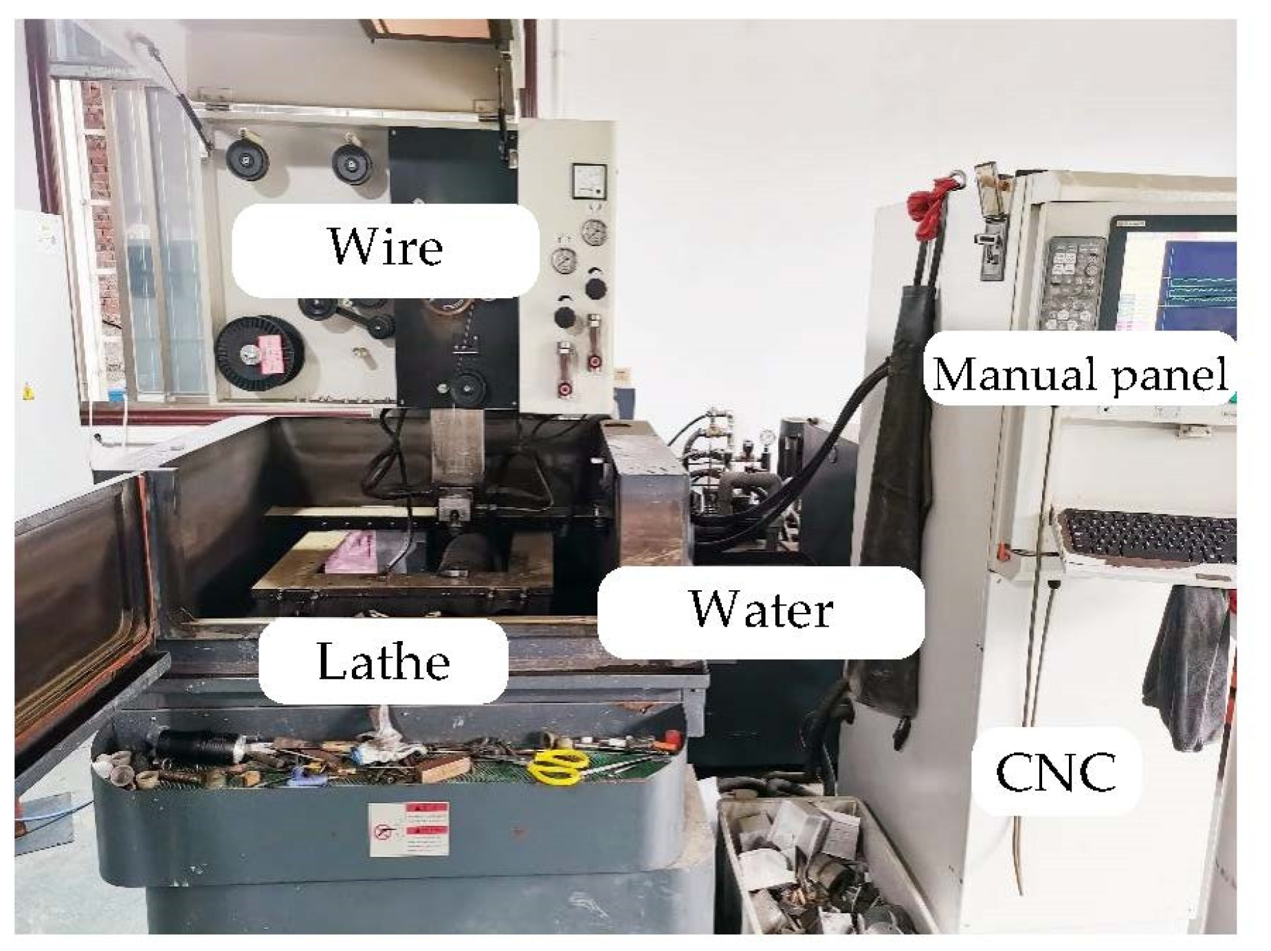
2.1. Machining Tools and Workpieces

In this work, the orthogonal experiment was conducted on a 5-axis low-speed wire electric discharge tool. Deionized water was also applied as the dielectric during the period of the machining. Figure 1 depicts the details of the machine tool. Additionally, the detailed parameters of the machine tool are described in Table 1. The diameter of both ZCSMWE and BWE is determined as 0.25 mm.
The workpiece material of this work was the SiC particle reinforced Al matrix with a volume fraction of 65%. It was produced by a pressure infiltration and its physical properties are listed in Table 2.

2.2. Experiment Design

Based on the previously reported experiments and our experiment experience [39,40,41,42], the Taguchi experiment with 5 factors and 5 levels was designed. In addition, experiments were applied with ZCSMWE and BWE for comparison. The following five factors are selected as pulse-on time (TON), pulse-off time (Toff), servo-voltage (SV), wire speed (WS) and wire tension (WT). Both MRR and Ra were chosen as the index of the machining performance, and the specific levels are presented in Table 3. The other processing parameters include: open voltage (85 V), discharge current (10 A) and feed rate (10 mm2/min).

2.3. Test Methods

(1)
MRR
The machining time was recorded by stopwatch and thus the MRR was calculated by Equation (1) [43,44].
M R R = L H t
where L is that cutting length constant that equals 10 mm, H is that workpiece thickness that equals 4 mm, and t stands for the machining time (units: s).
(2)
Surface roughness
The surface roughness was measured by employing an optical profilometer at 5× magnification. Ra was chosen to represent surface roughness.
(3)
Surface topography and chemical composition
The machined surface microstructural and its chemical composition were characterized by employing a scanning electrical microscope equipped with an energy dispersive spectrometer. The results were observed at 20 kV, with 500× magnification.

3. The Preparation Method of Zinc Coating and Surface Microstructure on Wire Electrode

The preparation process of the ZCSMWE includes: casting, coating, annealing and plastic processing, as shown in Figure 2.
(1)
Casting: The main material of the wire core was brass, which is composed of zinc (25 wt.%) and copper (74.8 wt.%). Some microelements were doped to improve the mechanical strength of the wire core, such as P (0.05 wt.%), Mg (0.05 wt.%) and Mn (0.08 wt.%). The temperature of the continuous casting was 950–1250 °C.
(2)
Coating: Due to the thermal corrosion effect, the wire electrode will wear or rupture in WEDM. The coating on the wire electrode will melt or vaporize before the wire core melts or vaporizes when the coating element has a low melting point. A part of thermal energy will be absorbed because of the latent heat of melting vaporizing. Then, the wear rate of the wire core will be reduced. Zinc was selected as the material of the coating layer in this paper. The electroplating method was chosen to form a zinc coating on the wire core. Before electroplating, the wire core completed the surface treatment of oil disposal, acid pickling and water rinsing. The electroplating current and electroplating voltage were 1500–3000 A and 150–220 V, respectively. The thickness of zinc coating was 5–20 μm. The copper and zinc alloy was formed on the interface of zinc coating and wire core after thermal alloying treatment at 390–440 °C for 2–10 h.
(3)
Annealing: The annealing temperature and time were 700 °C and 3 s, respectively. After high-temperature annealing, the compressive stress in the wire core and the tensile stress will form since the thermal expansion coefficient of the wire core is higher than that of the coating layer. Then, the surface of the wire electrode will split because of the unbalanced stress in the wire electrode.
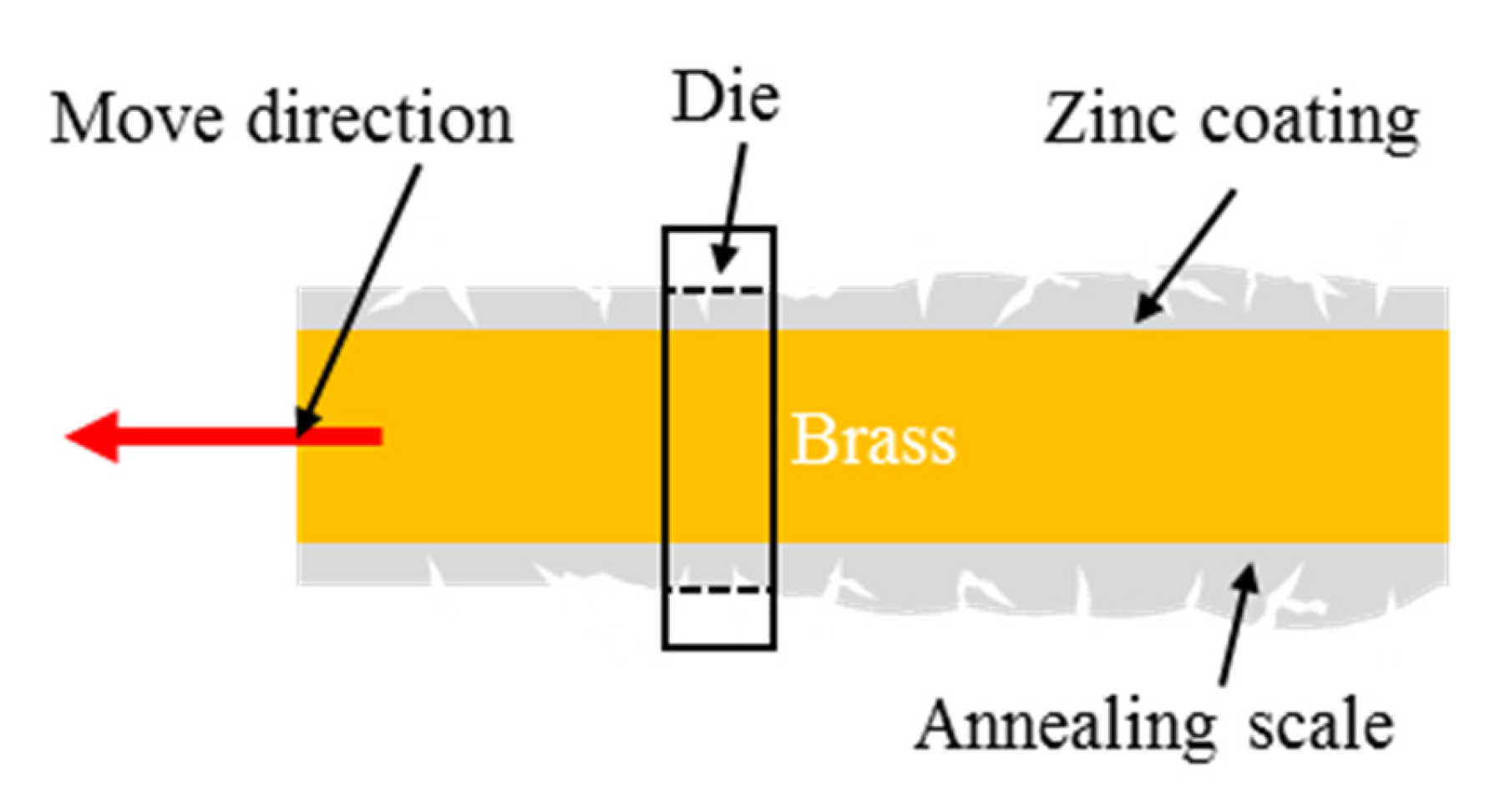
(4)
Plastic processing: The aim of plastic processing is to remove the scale after high-temperature annealing. As shown in Figure 3, the annealing scale will form on the wire electrode after annealing treatment. To remove the annealing scale, the wire electrode passes through a die with a diameter of 0.25 mm. Then, the microstructure of micro pits and microcracks will be exposed on the wire electrode.
Figure 4 shows the cross section and surface topography of the ZCSMWE. The cross section of ZCSMWE was treated by grinding, polishing and ultrasonic cleaning. The image of the cross section of ZCSMWE is observed by a metallographic microscope. The surface topography of ZCSMWE is observed by a scanning electrical microscope. It was found that the thickness of the Zinc coating was about 8–16 μm. The surface microstructure consists of a 5–10 μm diameter of the micro pit and a 10–50 μm length of the micro groove.
Table 4 displays the EDS results of the wire core and the surface of ZCSMWE. It is observed that the content of the copper element within the wire core of the ZCSMWE is relatively high, while Zn is relatively low, being 13.7% and 21.6%, respectively, which corresponds to the above introduction. After the tensile test, Young’s modulus of the ZCSMWE was 310 MPa, and BWE was 280 MPa, indicating that the ZCSMWE is less prone to rupture than BWE.

4. The Influences of ZCSMWE on the Machining Characteristics

4.1. MRR and Ra

Five factors and five levels of the Taguchi experiment were designed. The results of the cutting experiment are shown in Table 5; it can be concluded that ZCSMWE is able to significantly improve both the MRR and the surface quality compared with BWE. More specifically, the MRR by ZCSMWE increased by 4.02–16.67% and the surface roughness decreased by 4.54–21.18%. The specific factors and results are divulged in Table 5. Furthermore, when processing 65 vol.% SiCp/Al by ZCSMWE, the phenomenon of the wire breaking is less than that by BWE. In other words, the high-volume content SiCp/Al can be processed stably with the ZCSMWE in WEDM. Moreover, Figure 5 shows the measuring image of the surface roughness of the No. 11 workpiece, which is measured by an optical profiler. It can be seen that the Ra on the workpiece surface machined by BWE and ZCSMWE is 5.42 μm and 4.57 μm, respectively. The height difference of the micro profile on the workpiece surface machined by BWE and ZCSMWE is 25.6 μm and 16.6 μm, respectively. In addition, the micro bulges and pits on the workpiece surface machined by ZCSMWE are smaller and more uniform than that by BWE.

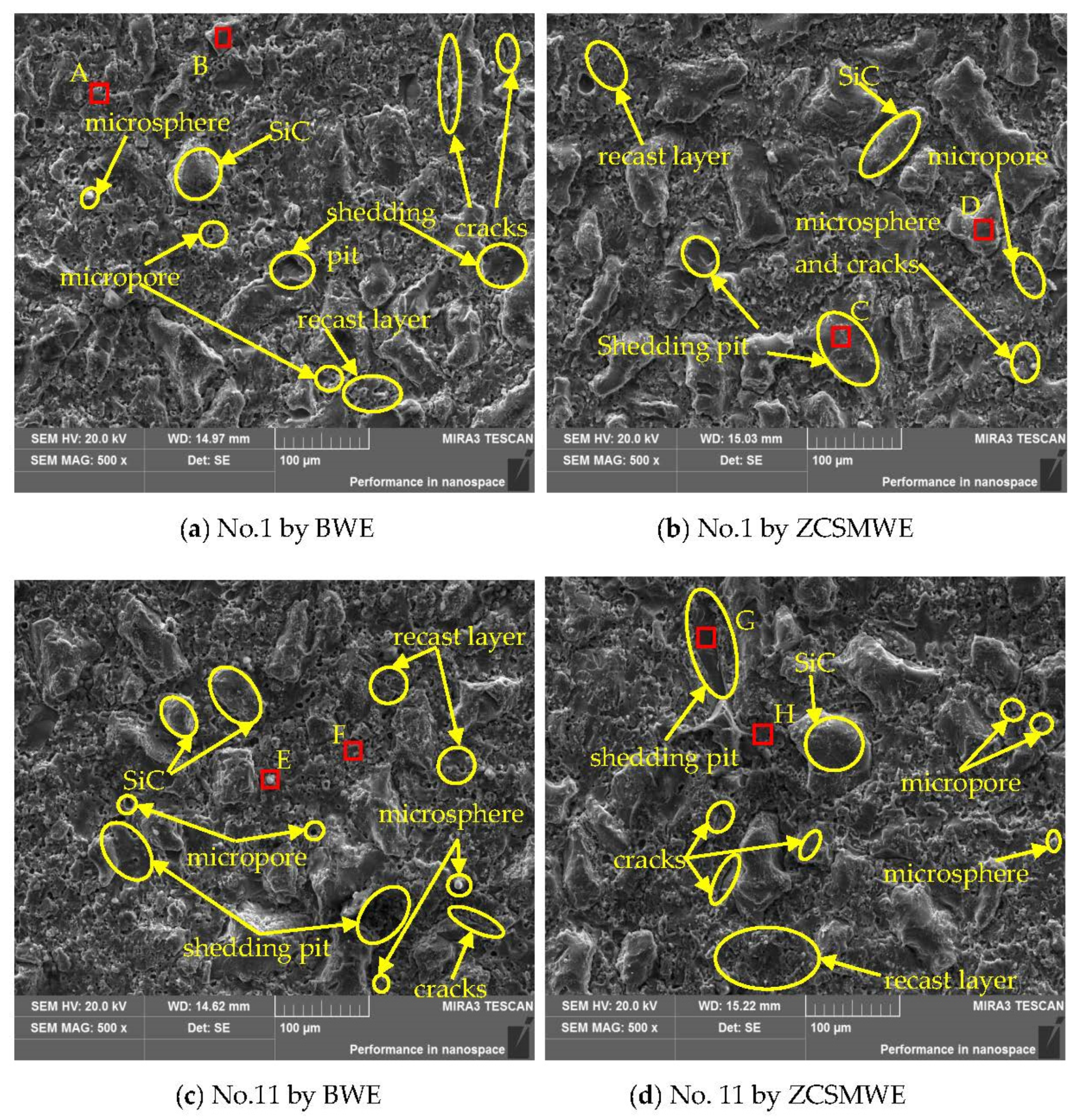
4.2. Workpiece Surface Topography

Figure 6 depicts the SEM diagram of the processed surface of the SiCp/Al. It can be found that, compared with BWE, the microspheres on the surface processed by ZCSMWE are rarer and smaller. In WEDM, if the discharge debris is not ejected by the flowing dielectric in time, a part of the material etched by a high temperature will stay in the discharge gap and be cooled down by the flowing dielectric, becoming balls and reattaching on the surface of the workpiece [45,46]. At the same time, a part of the debris will be adsorbed on the surface, hence forming the recast layer [47,48,49,50,51]. In addition, the cracks on the machining surface by ZCSMWE are both shorter and narrower, while the cracks on the machining surface by BWE are longer and wider. According to the theory of fracture mechanics, the effective width of the crack is positively correlated with its depth [52,53,54]. Therefore, it can be concluded that ZCSMWE is helpful in improving surface quality.
Table 6 and Figure 7 show the acquired energy dispersive spectroscopy (EDS) analysis results of workpiece surfaces in Figure 6. As can be concluded from Table 6 and Figure 7, both the oxidation and element transfer effects occurred when processing the SiCp/Al composite in WEDM [55,56,57,58]. It can be found that oxygen atoms generally take more account of the workpiece surface processed by BWE than those processed by ZCSMWE by enforcing the same processing parameters. Furthermore, a small amount of copper and zinc were found on the workpiece surface, indicating that the elements of the wire electrode were transferred from the surface of the wire to the workpiece surface during processing. By considering that both the workpiece material and the wire electrode would be etched at the same time due to the high temperature in WEDM, a small part of the wire electrode will be etched and re-attached to the processed surface of the workpiece after being cooled down by the dielectric. As can be observed from Table 6, in general, the migratory elements from the wire electrode of ZCSMWE are less than that of BWE. In other words, the discharge debris that is attached to the processed surface is significantly reduced and the surface morphology of the workpiece is improved.

4.3. Wire Rupture

Table 7 shows the wire rupture times of both BWE and ZCSMWE. It can be seen that, when BWE is used, most wire rupture times are one after the completed 10 mm cutting length under different process parameters. The wire rupture times are two at the relatively high material removal rate (0.34 mm2/s). When ZCSMWE is used, most wire rupture times are zero after the completed 10 mm cutting length. However, wire rupture occurs at a relatively high material removal rate (0.37 mm2/s). It means that, compared with BWE, ZCSMWE can significantly reduce the wire rupture frequency. The wire rupture frequency may increase with the material removal rate.
To further investigate the wire rupture at the relatively high material removal rate, several groups are selected from Table 5, as illustrated in Table 8. The same workpiece is applied and the process length was increased to 20 mm to obtain more reliable data. As can be found in Table 8, BWE owns a shorter stable process time and more frequent wire rupture times compared with ZCSMWE. More specifically, the longest stable cutting time is 180 s with wire rupture one time and the maximum times of wire rupture are three by BWE, while the longest cutting time by ZCSMWE is 262 s with the detection of no wire rupture.
As is mentioned in the above Section 1, the frequent wire rupture during the processing of the SiCp/Al structure in WEDM mainly comes from the irregular distribution of the high-volume fraction of SiC particles within the aluminum matrix. Since the surrounding aluminum is corroded, SiC particles fall into the discharge gap. As a result, there will be a considerable amount of detached insulation SiC particles within the narrow discharge gap, deteriorating the discharge condition, enhancing the discharge instability and then promoting the wire rupture effect.
Figure 8 depicts the SEM results of the wire electrode. From the acquired images it can be found that the discharge removing crater on the ZCSMWE is evener and thinner. On top of that, as a contrast, the surface topography of the processed BWE is much more complex with discrete, thicker discharge debris forming deeper and larger pits on the wire electrode surface. It is suggested that due to more discharge debris in the discharge channel and the higher temperature during the processing applied with BWE, the discharge condition is relatively poor. In addition, the arc and secondary discharges appear more frequently [59,60], over-processing both the wire electrode and the workpiece, and damaging the workpiece surface, which is consistent with the above-mentioned conclusions.
Table 9 illustrates the surface chemical composition of both ZCSMWE and BWE in Figure 8 before and after the process. As can be observed from Table 5, the MRR by ZCSMWE is generally higher than that by BWE; hence, more discharge debris would be generated when applied with ZCSMWE in WEDM. However, as is suggested in Table 9, the relative atomic content of both Al and Si on the BWE surface increases more than those of ZCSMWE. The implementation of a narrower discharge channel and higher temperature by BWE lead to the belated ejection of the discharged debris and their longer duration in the discharge channel. It is interesting to notice that not only more melted material will adhere to the wire electrode surface, but also the secondary discharge increases, damaging the surface of the workpiece. Moreover, the stranded insulating SiC particles make wire rupture appear more frequently, thus reducing the processing stability. Additionally, the relative atomic contents of Al and Si of ZCSMWE and BWE are not changed obviously before and after the application of the process. This effect could be originated from the underlying processing mechanism of SiCp/Al in WEDM, which is different from that of the pure metal materials. Specifically speaking, according to previously reported studies, during the processing of pure metal materials, pure metal was melted into liquid and ZCSMWE can adsorb plenty of the removed metal, which is conducive to the ejection of the discharged debris and the improvement of the discharge condition. As Figure 6 and Figure 8 indicate, the size of the SiC particles ranges from 50 to 150 μm, whereas the crack size of ZCSMWE is about 5–20 μm. The shedding SiC particles were not allowed to enter the cracks of ZCSMWE and be taken out. In addition, the Cu and Zn on the BWE surface decrease more than that on ZCSMWE, indicating less elemental transfer happens due to lower temperature with ZCSMWE, which is consistent with the EDS results of workpieces and the analysis in Section 4.2.

5. The Improvement Mechanism of ZCSMWE on the Machining Characteristics

5.1. The Effect of Zinc Coating

(1)
The low work function of zinc
The work function of zinc is less than copper (5.41 × 10⁻¹⁹ J and 7.52 × 10⁻¹⁹ J, respectively) [61,62,63]. Namely, the energy required for the zinc to escape from the surface is easier to achieve compared to that of the copper. This is helpful to promote the forming of the discharge channel. Then, it will bring some benefits: (a) the distance required for breaking down the dielectric is further, which signifies that a wider discharge channel appears, allowing more dielectric to flow in and bring out more discharge debris. Since the discharge channel is narrow (about 0.025 mm for 0.25 mm wire diameter), it is quite difficult to expel the discharge debris [64,65,66]. (b) The abnormal discharge in WEDM (such as short circuit and secondary discharge) mainly originates from the discharge debris in the discharge channel, while the abnormal discharge will significantly damage the surface quality. Therefore, as more discharge debris is expelled, better discharge conditions appear, whereas the secondary discharge is reduced and both the recast and white layers are diluted. As a result, a better surface topography will be formed. Furthermore, the manifestation of a wider discharge channel with more dielectric is advantageous to the ejection of the discharge debris and SiC particles, contributing to the reduced wire rupture phenomenon when processing particle-reinforced composites material. (c) Less energy is required for breaking down the dielectric and more flowing in the dielectric to cooldown, while the lower temperature will be maintained during the processing [67].
(2)
The low boiling temperature of zinc
Since the work function of zinc is lower and it is more likely to be dislodged from the surface under the application of an electric field, the processing temperature by ZCSMWE is reduced. In addition, zinc possesses a lower melting and boiling point than copper (419.5 °C melting, 907 °C boiling for zinc and 1083 °C melting, 2562 °C boiling for copper). Namely, the melting and boiling of zinc are more toilless, which can possibly further reduce the processing temperature in WEDM. At the same time, the oxidation reaction is closely related to the local temperature distribution. More specifically, at a lower temperature, the oxidation reaction rate can be retarded, homologously, whereas the surface quality of the workpiece is improved. Moreover, the higher temperature can result in stronger erosion of the wire electrode, making the BWE thinner during the processing. Obviously, the more fragile structures are more likely to rupture. In addition, ZCSMWE enables more discharge debris to be expelled, especially the distributed insulating SiC particles in the discharge channel, so that the discharge becomes relatively stable. In addition, the wider discharge channel allows an enhanced amount of dielectric to enter in and subsequently decrease the temperature, which may impose less erosion by ZCSMWE, contributing to the process stability.
In EDM, due to the high temperature, the removed materials from the anode and the cathode will be evolved into steam and jet into the discharge gap at the discharge point. Moreover, the jets from the two electrodes will meet at one point and then a collision event will happen, interacting with each other and finally generating a shear force that will push the materials and discharge debris out. The shear force is also considered a processing mechanism in EDM. Under this point of view, Yang Xiaodong investigated the machining performance and deduced the size of the discharge gap in EDM applied with zinc, brass and copper electrodes [68]. Interestingly, it was found that when the discharge time was less than 24 μs, the MRR of the zinc electrode was higher and the discharge gap was wider. Although the manifestation of a wider discharge gap led to the decrease in both the heat flow and temperature during processing, the influence of the shear force was greater than the influence of the discharge gap, so the zinc electrode had a greater MRR. Similarly, the mechanism of WEDM is similar to that of EDM. Along these lines, steam and shear stress will be developed, as is shown in Figure 9. Since the zinc-coated surface on ZCSMWE has a lower boiling point, wider discharge channels and stronger shear force, more workpiece material will be removed even at lower temperatures.
In addition, due to the lower temperature and similar thermal conductivity (zinc 116 W/(m·K) and copper 108.9 W/(m·K)), the zinc electrode exhibits lower wear in EDM, which can depress the element transfer phenomenon during the processing, resulting in a better surface quality of the zinc electrode. This conclusion is consistent with previously reported results.
Additionally, it was pointed out that in WEDM, the lower boiling point of zinc may lead to the creation of denser steam with higher jets velocity, which can take out more removed materials and discharge debris [69]. Notably, more insulating SiC particles within the discharge channel would be pushed out, promoting a more stable discharge. Moreover, the jet collision points are much closer to the workpiece and the direction of the shear forces would become horizontal, making the discharge craters processed by the zinc electrode bigger and shallower. This effect implies that the zinc electrode has a higher MRR and lower surface roughness when machining metal materials are employed.

5.2. The Effect of Surface Microstructure

(1)
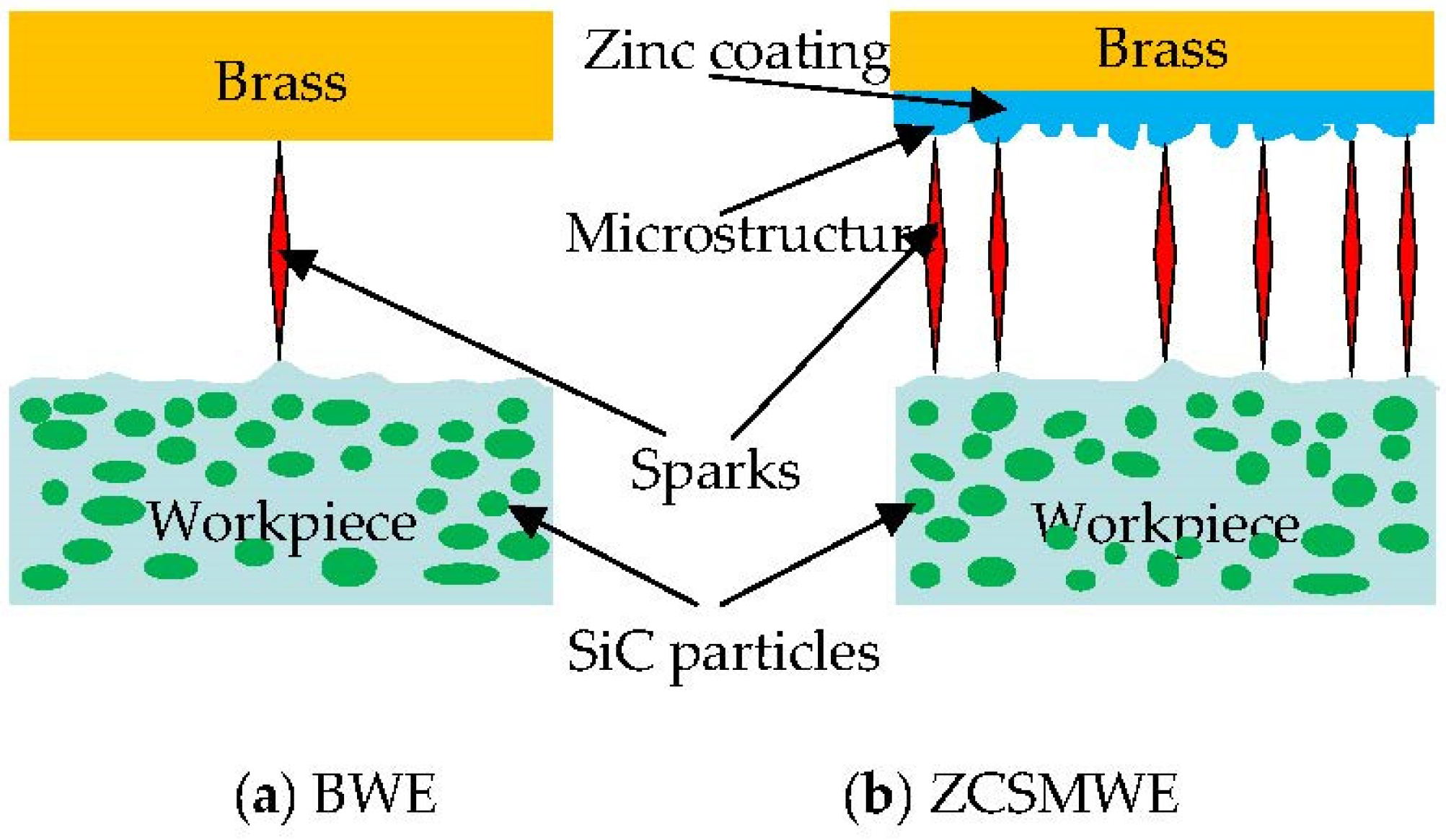
Promoting the discharge points more uniformly distributed
In WEDM, the application of an ultrahigh electric field (1 × 10⁶~1 × 10⁹ V/cm) by constantly feeding two energized poles is required to compel the electrons of the electrode to escape from the surface (field emission phenomenon). The electrons will be consequently accelerated by the field and bombard the surface of the workpiece, transforming their kinetic energy into heat and producing plenty of thermal erosion phenomenon of the workpiece material. From a theoretical point of view, when the workpiece surface is absolutely smooth, after the breakdown of the dielectric in the discharge gap, the electric field strength ought to be uniform and it will discharge evenly within the discharge channel. However, as is shown in Figure 10, the workpiece surface cannot be absolutely smooth, since some irregular convex can be observed. When an external voltage is applied to the wire electrode, the strongest field intensity will be firstly achieved at the regions of the convex. As a result, the electrons will be gathered in the small distance between the wire electrode and workpiece, whereas the discharge channel will be established for promoting the discharge process, contributing to the concentration of discharging at small parts of the region. Therefore, as a consequence of the undue processing, a large number of deep pits and more microcracks will be generated that will inevitably damage the surface quality. While many irregular protrusions on the surface by ZCSMWE can be observed, this will correspond to the workpiece surface convex. The microstructure on ZCSMWE can reduce the discharge spark concentration phenomenon. In other words, when the wire electrode is being fed close to the workpiece, the discharge point can be produced in multiple locations of the workpiece so as to avoid the phenomenon of centralized discharge and undue processing for the improvement of the surface quality. Furthermore, since the zinc layer is easier to be vaporized, the dissipated heat of the wire electrode will be conducted to the discharge gap by the steam from the tool electrode, which remarkably reduces the temperature of the electrode wire and the wire rupture in WEDM.
(2)
Promoting the dielectric circulation
As is shown in Figure 11, the experiments designed for the dielectric by ZCSMWE and BWE are illustrated as follows: (a) Two hosepipes are cut at the same length and filled with water; (b) A specially made rubber plug is applied to block the one side to ensure that water cannot outflow due to gravity; (c) The wire electrode traverses the rubber plug through the hole whose diameter is the same as wire electrode; (d) The wire electrode is electrified and removed. Therefore, water will be taken out by the movement of the wire electrode through the hole; (e) The time spent for the water to reach the two specific locations in the hosepipe by ZCSMWE and BWE is recorded. The specific experimental parameters are as follows: wire electrode diameter: 0.25 mm, hosepipe diameter: 4 mm, wire feed speed: 8 mm/s. The acquired results are shown in Table 10.
It is demonstrated that the shortest time spent to reach the specified location by ZCSMWE is 61 s with an average time of 67.5 s, while the time by BWE is just 84 s and 90 s from Table 10. Obviously, compared with BWE, ZCSMWE can increase dielectric cycling speed by about 25%, which means that ZCSMWE has a better drainage capability and chip removal capability.
The better drainage capacity of ZCSMWE mainly stems from its surface microstructure. Under this direction, the surface of BWE is smooth without Zn coating and its cracks, while the cracks on the ZCSMWE surface have the ability to absorb and store more water, which accelerates the ejection efficiency of the water exit from the processing area with the movement of the wire electrode. Due to the better drainage capacity, more discharge debris can be brought out with dielectric, whereas the secondary discharge during processing is reduced, the density of insulation SiC particles within the discharge gap is weakened and the stability of wire is strengthened. This interpretation is consistent with the previous analysis. In addition, the better drainage capacity of ZCSMWE is beneficial in promoting discharge debris to be expelled and reducing the temperature in the discharge gap, which is helpful to restrain wire rupture and microcracks on the workpiece surface.

6. Conclusions

The main conclusions can be drawn as follows:
  • Under the same parameters, compared with BWE, ZCSMWE can increase MRR by 16.67% and decrease Ra by 21.18%. ZCSMWE can also improve the surface quality, such as reducing recast layer thickness, microspheres, microcracks and oxidation.
  • Compared with BWE, ZCSMWE can decrease the size of the discharge crater and improve the uniformity of the discharge crater on the wire electrode. ZCSMWE can also improve the process stability in terms of stable process and wire rupture times. This is because the microstructure on ZCSMWE can reduce the discharge spark concentration phenomenon. Zinc coating vaporizes easily, which can reduce the temperature of the discharge gap and protect the wire core from melting and vaporizing.
  • Compared with BWE, ZCSMWE can increase the dielectric cycling speed by about 25%. The better dielectric circulation promotes more discharge debris to be expelled out and reduces the temperature in the discharge gap, which is helpful to restrain wire rupture and microcracks on the workpiece surface.

Author Contributions

Conceptualization, Z.C. and H.Z.; Data curation, H.Z., C.W. and H.Y.; Funding acquisition, Z.C., G.Z. and H.Y.; Investigation, C.W; Methodology, Z.C.; Resources, Z.C., G.Z. and H.Y.; Writing—original draft, Z.C. and H.Z.; Writing—review & editing, H.Y. All authors have read and agreed to the published version of the manuscript.

Funding

This research is supported by the National Natural Science Foundation of China (Grant No. 51805552), Natural Science Foundation of Hunan Province, China (Grant No. 2020JJ5721), Fundamental Research Funds for the Central Universities of Central South University (Grant No. 2022zzts0786), Natural Science Foundation of Guangdong Province, China (Grant No. 2022A1515011226), Central Government Funds for Guiding Local Scientific and Technological Development (Grant No. 2021Szvup167) and the project of Guangdong Provincial Key Laboratory of Manufacturing Equipment Digitization (Grant No. 2020B1212060014).

Institutional Review Board Statement

Not applicable.

Informed Consent Statement

Not applicable.

Data Availability Statement

Not applicable.

Conflicts of Interest

All authors declare that they have no known competing financial interests or personal relationships that could have appeared to influence the work reported in this paper.

References

  1. Ekici, R.; Kosedag, E.; Demir, M. Repeated low-velocity impact responses of SiC particle reinforced Al metal-matrix composites. Ceram Int. 2022, 48, 5338–5351. [Google Scholar] [CrossRef]
  2. Wang, Y.; Wei, W.; He, X.; Lan, X.; Sha, A.; Hao, W. Effects of Strength and Distribution of SiC on the Mechanical Properties of SiCp/Al Composites. Materials 2022, 15, 1288. [Google Scholar] [CrossRef] [PubMed]
  3. Jiang, X.D.; Xiao, D.H.; Teng, X.Y. Influence of vibration parameters on ultrasonic vibration cutting micro-particles reinforced SiC/Al metal matrix composites. Int. J. Adv. Manuf. Technol. 2022, 119, 6057–6071. [Google Scholar] [CrossRef]
  4. Mattli, M.R.; Matli, P.R.; Khan, A.; Abdelatty, R.H.; Yusuf, M.; Ashraf, A.A.; Kotalo, R.G.; Shakoor, R.A. Study of Microstructural and Mechanical Properties of Al/SiC/TiO2 Hybrid Nanocomposites Developed by Microwave Sintering. Crystals 2021, 11, 1078. [Google Scholar] [CrossRef]
  5. Singh, S.; Pal, K. Effect of texture evolution on mechanical and damping properties of SiC/ZnAl2O4/Al composite through friction stir processing. J. Mater. Res. Technol. 2019, 8, 222–232. [Google Scholar] [CrossRef]
  6. Bhoi, N.K.; Singh, D.H.; Pratap, S. Developments in the aluminum metal matrix composites reinforced by micro/nano particles—A review. J. Compos. Mater. 2020, 54, 813–833. [Google Scholar] [CrossRef]
  7. Zhang, J.F.; Andrä, H.; Zhang, X.X.; Wang, Q.Z.; Xiao, B.L.; Ma, Z.Y. An enhanced finite element model considering multi strengthening and damage mechanisms in particle reinforced metal matrix composites. Compos. Struct. 2019, 226, 10. [Google Scholar] [CrossRef]
  8. Ahlhelm, M.; Günther, P.; Scheithauer, U.; Schwarzer, E.; Günther, A.; Slawik, T.; Moritz, T.; Michaelis, A. Innovative and novel manufacturing methods of ceramics and metal-ceramic composites for biomedical applications. J. Eur. Ceram. Soc. 2016, 36, 2883–2888. [Google Scholar] [CrossRef]
  9. Mao, Y.; Li, J.X.; Vivek, A.; Daehn, G.S. High strength impact welding of 7075 Al to a SiC-reinforced aluminum metal matrix composite. Mater. Lett. 2021, 303, 130549. [Google Scholar] [CrossRef]
  10. Chen, Z.; Zhang, Y.M.; Zhang, G.J.; Huang, Y.; Liu, C. Theoretical and experimental study of magnetic-assisted finish cutting ferromagnetic material in WEDM. Int. J. Mach. Tool Manuf. 2017, 123, 36–47. [Google Scholar] [CrossRef]
  11. Wang, R.Q.; Huang, J.Y.; Liu, Q.; Wu, S.; Wu, J.; Ren, X.; Li, Y. The effect of particle size and mass ratio on the mechanical response of Al/PTFE/SiC composite with a 2(3) factorial design. RSC Adv. 2022, 12, 2810–2819. [Google Scholar] [CrossRef] [PubMed]
  12. Bian, R.; He, N.; Li, L.; Zhan, Z.B.; Wu, Q.; Shi, Z.Y. Precision milling of high volume fraction SiCp/Al composites with monocrystalline diamond end mill. Int. J. Adv. Manuf. Technol. 2014, 71, 411–419. [Google Scholar] [CrossRef]
  13. Ho, K.H.; Newman, S.T.; Rahimifard, S.; Allen, R.D. State of the art in wire electrical discharge machining (WEDM). Int. J. Mach. Tool Manuf. 2004, 44, 1247–1259. [Google Scholar] [CrossRef]
  14. Li, Z.L.; Liu, Y.T.; Cao, B.R.; Li, W. Modeling of material removal morphology and prediction of surface roughness based on WEDM successive discharges. Int. J. Adv. Manuf. Technol. 2022, 120, 2015–2029. [Google Scholar] [CrossRef]
  15. Zhang, Y.; Zhang, G.; Zhang, Z.; Zhang, Y.; Huang, Y. Effect of assisted transverse magnetic field on distortion behavior of thin-walled components in WEDM process. Chin. J. Aeronaut. 2022, 35, 291–307. [Google Scholar] [CrossRef]
  16. Chen, Z. Study on the white layer in wire electrical discharge trim cutting of bearing steel GCr15. Int. J. Adv. Manuf. Technol. 2019, 102, 375–2386. [Google Scholar] [CrossRef]
  17. Ming, W.Y.; Zhang, S.F.; Zhang, G.J.; Du, J.; Ma, J.; He, W.; Cao, C.; Liu, K. Progress in modeling of electrical discharge machining process. Int. J. Heat Mass Transf. 2022, 187, 122563. [Google Scholar] [CrossRef]
  18. Shastri, R.K.; Mohanty, C.P.; Dash, S.; Gopal, K.M.P.; Annamalai, A.R.; Jen, C.-P. Reviewing Performance Measures of the Die-Sinking Electrical Discharge Machining Process: Challenges and Future Scopes. Nanomaterials 2022, 12, 384. [Google Scholar] [CrossRef]
  19. Ming, W.Y.; Jia, H.J.; Zhang, H.M.; Zhang, Z.; Liu, K.; Du, J.; Shen, F.; Zhang, G. A comprehensive review of electric discharge machining of advanced ceramics. Ceram Int. 2020, 46, 21813–21838. [Google Scholar] [CrossRef]
  20. Satishkumar, D.; Kanthababu, M.; Vajjiravelu, V.; Anburaj, R.; Sundarrajan, N.T.; Arul, H. Investigation of wire electrical discharge machining characteristics of Al6063/SiCp composites. Int. J. Adv. Manuf. Technol. 2011, 56, 975–986. [Google Scholar] [CrossRef]
  21. Yang, W.S.; Chen, G.Q.; Wu, P.; Hussain, M.; Song, J.-B.; Dong, R.-H.; Hui, G. Electrical Discharge Machining of Al2024-65 vol% SiC Composites. Acta Metall Sin. 2017, 30, 447–455. [Google Scholar] [CrossRef] [Green Version]
  22. Wang, Z.L.; Geng, X.S.; Chi, G.X.; Wang, Y. Surface Integrity Associated with SiC/Al Particulate Composite by Micro-Wire Electrical Discharge Machining. Mater. Manuf. Process. 2014, 29, 532–539. [Google Scholar]
  23. Murari, V.P.G.; Selvakumar, G.; Sastry, C.C. Experimental Investigation of Wire-EDM Machining of Low Conductive Al-SiC-TiC Metal Matrix Composite. Metals 2020, 10, 1188. [Google Scholar]
  24. Kumar, H.; Manna, A.; Kumar, R. Modeling of Process Parameters for Surface Roughness and Analysis of Machined Surface in WEDM of Al/SiC-MMC. Trans. Indian Inst. Met. 2018, 71, 231–244. [Google Scholar] [CrossRef]
  25. Chen, Z.; Zhang, Y.M.; Zhang, G.J.; Li, W. Modeling and reducing workpiece corner error due to wire deflection in WEDM rough corner-cutting. J. Manuf. Process. 2018, 36, 557–564. [Google Scholar] [CrossRef]
  26. Sen, R.; Choudhuri, B.; Barna, J.D.; Chakraborti, P. An investigation on the effect of different coated electrodes on the surface quality of WEDM by varying discharge energy level. Int. J. Adv. Manuf. Technol. 2020, 106, 3285–3299. [Google Scholar] [CrossRef]
  27. Muthuramalingam, T.; Ramamurthy, A.; Sridharan, K.; Ashwin, A. Analysis of surface performance measures on WEDM processed titanium alloy with coated electrodes. Mater. Res. Express. 2018, 5, 126503. [Google Scholar] [CrossRef]
  28. Goyal, A. Investigation of material removal rate and surface roughness during wire electrical discharge machining (WEDM) of Inconel 625 super alloy by cryogenic treated tool electrode. J. King Saud Univ. Sci. 2017, 29, 528–535. [Google Scholar] [CrossRef]
  29. Li, L.; Wong, Y.S.; Fuh, J.Y.H. EDM performance of TiC/copper-based sintered electrodes. Mater. Design. 2001, 22, 669–678. [Google Scholar] [CrossRef]
  30. Bose, S.; Nandi, T. Experimental investigation of WEDM on titanium hybrid composite reinforced with boron powder: A novel approach. Eur. Phys. J. Plus 2020, 135, 914. [Google Scholar] [CrossRef]
  31. Saha, A.; Mondal, S.C. Multi-objective optimization in WEDM process of nanostructured hardfacing materials through hybrid techniques. Measurement 2016, 94, 46–59. [Google Scholar] [CrossRef]
  32. Manjaiah, M.; Narendranath, S.; Basavarajappa, S.; Gaitonde, V.N. Effect of electrode material in wire electro discharge machining characteristics of Ti50Ni50−xCux shape memory alloy. Precis. Eng. 2015, 41, 68–77. [Google Scholar] [CrossRef]
  33. Sharma, P.; Chakradhar, D.; Narendranath, S. Effect of Wire Material on Productivity and Surface Integrity of WEDM-Processed Inconel 706 for Aircraft Application. J. Mater. Eng. Perform. 2016, 25, 3672–3681. [Google Scholar] [CrossRef]
  34. Radhakrishnan, P.; Vijayaraghavan, L.; Babu, N.R. Assessment of material removal capability with vibration-assisted wire electrical discharge machining. J. Manuf. Process. 2017, 26, 323–329. [Google Scholar]
  35. Sen, R.; Choudhuri, B.; Barma, J.D.; Chakraborti, P. Surface integrity study of WEDM with various wire electrodes: Experiments and analysis. Mach. Sci. Technol. 2020, 24, 569–591. [Google Scholar] [CrossRef]
  36. Yan, H.; Kabongo, B.D.; Zhou, H.; Wu, C.; Chen, Z. Analysis and Optimization of the Machining Characteristics of High-Volume Content SiCp/Al Composite in Wire Electrical Discharge Machining. Crystals 2021, 11, 1342. [Google Scholar] [CrossRef]
  37. Chen, Z.; Zhou, H.B.; Yan, Z.J.; Han, F.; Yan, H. Machining characteristics of 65 vol.% SiCp/Al composite in micro-WEDM. Ceram Int. 2021, 47, 13533–13543. [Google Scholar] [CrossRef]
  38. Chen, Z.; Yan, Z.J.; Zhou, H.B.; Han, F.; Zhao, L.; Yan, H. One-step fabrication of the wear-resistant superhydrophobic structure on SiCp/Al composite surface by WEDM. Surf. Coat. Technol. 2021, 409, 126876. [Google Scholar] [CrossRef]
  39. Chen, Z.; Zhou, H.B.; Yan, Z.J.; Han, F.; Yan, H. A new high-speed observation system for evaluating the spark location in WEDM of Inconel 718. J. Mater. Res. Technol. 2021, 13, 184–196. [Google Scholar] [CrossRef]
  40. Yan, H.Z.; Bakadiasa, B.D.; Yan, Z.J.; Han, F.; Chen, Z. Sustainable production of high-uniformity workpiece surface quality in wire electrical discharge machining by fabricating surface microstructure on wire electrode. J. Clean. Prod. 2020, 259, 120881. [Google Scholar] [CrossRef]
  41. Chen, Z.; Yan, Z.J.; Yan, H.Z.; Han, F. Improvement of the machining characteristics in WEDM based on specific discharge energy and magnetic field-assisted method. Int. J. Adv. Manuf. Technol. 2019, 103, 3033–3044. [Google Scholar] [CrossRef]
  42. Yan, H.Z.; Bakadiasa, B.D.; Chen, Z.; Yan, Z.; Zhou, H.; Han, F. Attainment of high corner accuracy for thin-walled sharp-corner part by WEDM based on magnetic field-assisted method and parameter optimization. Int. J. Adv. Manuf. Technol. 2020, 106, 4845–4857. [Google Scholar] [CrossRef]
  43. Zhang, G.J.; Li, W.Y.; Zhang, Y.M.; Huang, Y.; Zhang, Z.; Chen, Z. Analysis and reduction of process energy consumption and thermal deformation in a micro-structure wire electrode electric discharge machining thin-wall component. J. Clean. Prod. 2020, 244, 118763. [Google Scholar] [CrossRef]
  44. Zhang, G.J.; Huang, H.; Zhang, Z.; Zhang, Y. Study on the effect of three dimensional wire vibration on WEDM based on a novel thermophysical model. Int. J. Adv. Manuf. Technol. 2019, 100, 2089–2101. [Google Scholar] [CrossRef]
  45. Chen, Z.; Huang, Y.; Huang, H.; Zhang, Z.; Zhang, G. Three-dimensional characteristics analysis of the wire-tool vibration considering spatial temperature field and electromagnetic field in WEDM. Int. J. Mach. Tool Manuf. 2015, 92, 85–96. [Google Scholar] [CrossRef]
  46. Yuan, Q.; Song, Y.C. Effect of SiCi(x)O(y) decomposition on densification of SiCO (Al) fibers during sintering process. J. Inorg. Mater. 2017, 31, 1320–1326. [Google Scholar]
  47. Li, C.J.; Xu, X.; Li, Y.; Tong, H.; Ding, S.; Kong, Q.; Zhao, L.; Ding, J. Effects of dielectric fluids on surface integrity for the recast layer in high speed EDM drilling of nickel alloy. J. Alloy. Compd. 2019, 783, 95–102. [Google Scholar] [CrossRef]
  48. Pramanik, A.; Basak, A.K.; Prakash, C.; Shankar, S.; Sharma, S.; Narendranath, S. Recast Layer Formation during Wire Electrical Discharge Machining of Titanium (Ti-Al6-V4) Alloy. J. Mater. Eng. Perform. 2022, 30, 8926–8935. [Google Scholar] [CrossRef]
  49. Zhang, M.; Liu, Z.D.; Pan, H.W.; Deng, C.; Qiu, M. Effect of no-load rate on recast layer cutting by ultra fine wire-EDM. Chin. J. Aeronaut. 2021, 34, 124–131. [Google Scholar] [CrossRef]
  50. Gholipoor, A.; Shabgard, M.; Arghavanian, R. Experimental Investigation of Recast Layer, Heat Affected Zone and Corrosion Resistance in WEDM of Inconel 617. J. Sci. Ind. Res. 2020, 79, 701–704. [Google Scholar]
  51. Wu, X.Y. Study of removing the recast layer by electrochemical dissolution with wire low feedrate in WEDM. Int. J. Adv. Manuf. Technol. 2019, 105, 1143–1156. [Google Scholar] [CrossRef]
  52. Mouralova, K.; Klakurkova, L.; Matousek, R.; Prokes, T.; Hrdy, R.; Kana, V. Influence of the cut direction through the semi-finished product on the occurrence of cracks for X210Cr12 steel using WEDM. Arch. Civ. Mech. Eng. 2018, 18, 1318–1331. [Google Scholar] [CrossRef]
  53. Mouralova, K.; Benes, L.; Bednar, J.; Zahradnicek, R.; Prokes, T.; Fries, J. Analysis of Machinability and Crack Occurrence of Steels 1.2363 and 1.2343ESR Machined by Die-Sinking EDM. Coatings 2020, 10, 406. [Google Scholar] [CrossRef]
  54. Isahak, A.H.; Adullah, M.F.; Faidzi, M.K.; Ali, A.; Mubasyir, M.M. Fatigue Crack Growth Behaviour of Sandwiched Metal Panel of Aluminium and Mild Steel under Constant Amplitude Loading. Int. J. Integr. Eng. 2020, 12, 81–90. [Google Scholar] [CrossRef]
  55. Kumar, A.; Sharma, R.; Gujral, R. Investigation of crack density, white layer thickness, and material characterization of biocompatible material commercially pure titanium (grade-2) through a wire electric discharge machining process using a response surface methodology. Proc. Inst. Mech. Eng. Part E J. Process Mech. Eng. 2021, 235, 2073–2097. [Google Scholar] [CrossRef]
  56. Al Zubaidi, F.N.; Walton, K.L.; Tompson, R.V.; Ghosh, T.K.; Loyalka, S.K. Emissivity of Grade 91 Ferritic Steel: Additional Measurements on Role of Surface Conditions and Oxidation. Nucl. Technol. 2020, 207, 1257–1269. [Google Scholar] [CrossRef]
  57. Kopp, A.; Smeets, R.; Jung, O.; Kröger, N.; Klink, A. Defined surface adjustment for medical magnesium implants by electrical discharge machining (EDM) and plasma electrolytic oxidation (PEO). Cirp Ann.-Manuf. Technol. 2019, 68, 583–586. [Google Scholar] [CrossRef]
  58. Guo, W.J.; Anantharajan, S.K.; Liu, K.; Deng, H. Investigation of Electrochemical Oxidation Behaviors and Mechanism of Single-Crystal Silicon (100) Wafer under Potentiostatic Mode. Coatings 2020, 10, 586. [Google Scholar] [CrossRef]
  59. Wang, Y.; Wang, Y.X.; Xiong, W.; Chai, H. Study on motion and distribution of debris in USV-MF complex-assisted WEDM-LS. Int. J. Adv. Manuf. Technol. 2021, 116, 667–683. [Google Scholar] [CrossRef]
  60. Pan, H.W.; Liu, Z.D.; Li, C.R.; Zhang, Y.; Qiu, M. Enhanced debris expelling in high-speed wire electrical discharge machining. Int. J. Adv. Des. Manuf. Technol. 2017, 93, 2913–2920. [Google Scholar] [CrossRef]
  61. Jubimol, J.; Sreejith, M.S.; Kartha, C.S.; Vijayakumar, K.P.; Louis, G. Analysis of spray pyrolysed copper zinc sulfide thin films using photoluminescence. J. Lumin. 2018, 203, 436–440. [Google Scholar] [CrossRef]
  62. Hegazy, S.A.; Abou-Gabal, H.; Soliman, M.B.; Hassan, M.H. Preparation and characterization of copper zinc tin sulfide-selenide thin films using a single target RF sputtering method. Thin. Solid Films 2019, 692, 137583. [Google Scholar] [CrossRef]
  63. Abd El-Gawad, A.H.M.; Khalil, A.A.I.; Gadallah, A.S. Influence of preparation conditions on the properties of silver doped copper-zinc sulfide thin films prepared via sol-gel spin coating technique. Optik 2021, 223, 165561. [Google Scholar] [CrossRef]
  64. Zahoor, S.; Azam, H.A.; Mughal, M.P.; Ahmed, N.; Rehman, M.; Hussain, A. WEDM of complex profile of IN718: Multi-objective GA-based optimization of surface roughness, dimensional deviation, and cutting speed. Int. J. Adv. Des. Manuf. Technol. 2021, 114, 2289–2307. [Google Scholar] [CrossRef]
  65. Sivaprakasam, P.; Hariharan, P. Surface characteristics of nano powder mixed micro-wire electrical discharge machining on inconel alloy. Mater. Today Proc. 2021, 38, 494–498. [Google Scholar] [CrossRef]
  66. Evran, S. Surface roughness and material removal rate analyses of hard copper alloy in wire electrical discharge machining. Emerg. Mater. Res. 2020, 9, 730–737. [Google Scholar] [CrossRef]
  67. Zhang, Y.Q.; Liu, Z.D.; Pan, H.W.; Qiu, M. Motion Characteristics of Discharge Channel in WEDM. Mater. Manuf. Processes 2021, 36, 583–598. [Google Scholar] [CrossRef]
  68. Yue, X.M.; Yang, X.D.; Kunieda, M. Comparison of Electrical Discharge Machining Speed of Tool Electrodes with Different Thermo-physical Properties Related to Ease of Boiling. Procedia CIRP 2018, 68, 138–143. [Google Scholar] [CrossRef]
  69. Yue, X.M.; Yang, X.D.; Kunieda, M. Influence of metal vapor jets from tool electrode on material removal of workpiece in EDM. Precis Eng. 2018, 53, 278–288. [Google Scholar] [CrossRef]
Figure 1. Practical map of the machine tools.
Materials 15 04098 g001
Figure 2. The preparation process of the ZCSMWE.
Materials 15 04098 g002
Figure 3. The schematic diagram of plastic processing during preparing zinc coating.
Materials 15 04098 g003
Figure 4. The cross section and surface topography of ZCSMWE: (a) Cross section; (b) Surface topography.
Materials 15 04098 g004
Figure 5. The measuring image of the workpiece surface roughness: (a) No. 11 by BWE; (b) No. 11 by ZCSMWE.
Materials 15 04098 g005
Figure 6. SEM images of the workpiece surface topography.
Materials 15 04098 g006
Figure 7. EDS result of the workpiece surface chemical composition.
Materials 15 04098 g007
Figure 8. SEM images of the wire electrode surface topography.
Materials 15 04098 g008
Figure 9. Interaction of jets under BWE and ZCSMWE.
Materials 15 04098 g009
Figure 10. Depiction of the discharge condition by BWE and ZCSMWE.
Materials 15 04098 g010
Figure 11. Depiction of the dielectric flow experiment by BWE and ZCSMWE.
Materials 15 04098 g011
Table 1. Detailed parameters of the machine tools.
Parameters Values
Maximum Current100 A
Open circuit voltage50–140 V
Pulse-on time50–1200 ns
Pulse-off time4–50 μs
Servo voltage16–75 V
Feed rate0.1–500 mm2/min
Wire tension 3–22 N
Table 2. Physical properties of the 65%vol. SiCp/Al [36,37,38].
Physical PropertiesValues
Density3.03 g/cm3
Thermal conductivity 200 W(m·k)@25 °C
Thermal expansion coefficient6.9 ppm
Young’s modulus188 GPa
shear modulus76 GPa
tensile strength488 MPa
Specific heat capacity 0.73 J/kg@25 °C
Table 3. Experimental parameters.
Parameter UnitSymbol
TonnsA
ToffμsB
SVVC
WSmm/sD
WTNE
Table 4. EDS chemical composition of the core and the surface of the ZCSMWE.
RegionFractionElements
COAlSiCuZn
Corewt.%21.483.180.230.0846.6728.36
at.%56.476.270.270.0923.1913.7
Surfacewt.%10.955.610.090.0239.7643.58
at.%35.6313.70.130.0324.4626.06
Table 5. Experimental design and results.
No.ABCDEMRRBRaBMRRSRaSImproM. %ImproR. %
1 150 10 41 8 11 0.20 4.70 0.22 4.14 11.48 11.95
2 150 11 43 9 12 0.17 4.55 0.20 4.30 15.08 5.41
3 150 12 45 10 13 0.16 4.89 0.18 4.64 15.77 5.05
4 150 13 47 11 14 0.14 4.74 0.16 4.37 13.77 7.81
5 150 14 49 12 15 0.13 4.43 0.14 4.18 8.30 5.64
6 200 10 43 10 14 0.20 4.97 0.23 4.48 14.29 9.86
7 200 11 45 11 15 0.19 5.12 0.20 4.51 4.02 11.91
8 200 12 47 12 11 0.18 4.91 0.18 4.68 4.11 4.68
9 200 13 49 8 12 0.15 5.18 0.17 4.93 14.17 4.83
10 200 14 41 9 13 0.19 5.31 0.22 4.80 15.00 9.60
11 250 10 45 12 12 0.22 5.42 0.24 4.57 9.70 15.68
12 250 11 47 8 13 0.19 5.03 0.21 4.65 12.50 7.55
13 250 12 49 9 14 0.16 5.22 0.19 4.74 15.74 9.20
14 250 13 41 10 15 0.21 5.13 0.24 4.77 13.77 7.02
15 250 14 43 11 11 0.21 5.32 0.22 5.05 7.78 5.08
16 300 10 47 9 15 0.24 5.57 0.28 5.25 16.67 5.75
17 300 11 49 10 11 0.21 5.35 0.24 5.06 14.12 5.42
18 300 12 41 11 12 0.26 5.68 0.30 5.23 14.81 7.92
19 300 13 43 12 13 0.24 5.43 0.28 4.28 13.79 21.18
20 300 14 45 8 14 0.22 5.37 0.24 4.28 9.70 20.30
21 350 10 49 11 13 0.27 5.30 0.29 4.56 7.19 13.96
22 350 11 41 12 14 0.34 5.07 0.37 4.84 9.26 4.54
23 350 12 43 8 15 0.30 5.20 0.33 4.33 9.76 16.73
24 350 13 45 9 11 0.26 5.14 0.29 4.73 9.35 7.98
25 350 14 47 10 12 0.23 5.24 0.25 4.39 8.86 16.22
MRRB: MRR by BWE, RaB: surface roughness of the BWE, MRRS: MRR by ZCSMWE, RaS: surface roughness of the ZCSMWE, ImproM.: the relative improvement of MRR from BWE to ZCSMWE, ImproR.: the relative improvement of Ra from BWE to ZCSMWE.
Table 6. Chemical composition of the workpieces surface.
RegionFractionElement
COAlSiCuZn
Awt.%26.2610.3210.7450.0520.63
at.%43.2812.767.8835.270.620.19
Bwt.%26.235.23.1563.531.550.34
at.%44.416.612.38460.490.11
Cwt.%37.834.390.2256.750.330.47
at.%57.635.020.1536.970.10.13
Dwt.%34.516.630.258.050.230.37
at.%53.497.720.1438.480.070.11
Ewt.%18.8253.3819.956.541.210.1
at.%26.5756.5912.543.950.320.03
Fwt.%23.9610.1624.1640.561.060.09
at.%4012.7317.9528.950.340.03
Gwt.%30.573.39.2556.540.090.25
at.%49.784.036.7139.380.030.07
Hwt.%41.8111.7826.4219.440.310.24
at.%59.0312.4916.6111.740.080.06
Table 7. Wire rupture times of both BWE and ZCSMWE.
No.ABCDEBRTSSRTS
1 150 10 41 8 11 1 0
2 150 11 43 9 12 1 0
3 150 12 45 10 13 1 0
4 150 13 47 11 14 1 0
5 150 14 49 12 15 1 0
6 200 10 43 10 14 1 0
7 200 11 45 11 15 1 0
8 200 12 47 12 11 1 0
9 200 13 49 8 12 1 0
10 200 14 41 9 13 1 0
11 250 10 45 12 12 1 0
12 250 11 47 8 13 1 0
13 250 12 49 9 14 1 0
14 250 13 41 10 15 1 0
15 250 14 43 11 11 1 0
16 300 10 47 9 15 1 0
17 300 11 49 10 11 1 0
18 300 12 41 11 12 1 0
19 300 13 43 12 13 1 0
20 300 14 45 8 14 1 0
21 350 10 49 11 13 1 0
22 350 11 41 12 14 2 1
23 350 12 43 8 15 1 0
24 350 13 45 9 11 1 0
25 350 14 47 10 12 1 0
BRTS: wire rupture times of BWE SRTS: wire rupture times of ZCSMWE.
Table 8. Stable process time and wire rupture times of both BWE and ZCSMWE.
No.ABCDEBST(s)BRTSSST(s)SRTS
1 300 12 41 11 12 180 1 262 0
2 350 11 41 12 14 95 3 183 1
3 350 12 43 8 15 160 2 240 0
BST: max stable process time of BWE, BRTS: wire rupture times of BWE, SST: max stable process time of ZCSMWE, SRTS: wire rupture times of ZCSMWE.
Table 9. Chemical composition of the wire electrode.
RegionFractionElement
COAlSiCuZn
Iwt.%11.662.360.13052.6833.18
at.%39.465.990.19033.7120.64
Jwt.%10.955.610.090.0239.7643.58
at.%35.6313.70.130.0324.4626.06
Kwt.%12.586.650.821.144929.81
at.%37.9315.051.11.4727.9316.52
Lwt.%10.359.990.550.5635.6742.87
at.%31.4122.760.740.7320.4623.9
Table 10. Time needed for the dielectric by BWE and ZCSMWE.
No.BWE(s)ZCSMWE(s)
18461
29674
Publisher’s Note: MDPI stays neutral with regard to jurisdictional claims in published maps and institutional affiliations.

