

Influence of the Geometrical Features of the Cutting Edges of Abrasive Grains on the Removal Efficiency of the Ti6Al4V Titanium Alloy

 , ,
, ,
Abstract
:1. Introduction
2. Materials and Methods
2.1. Experiment and Model Validation
- Sample displacement system with pneumatic drive;
- Phantom v12.1 high-speed camera with an optical system which allowed for ×100 magnification;
- Spotlight with illuminance of 4.6 million lux.
2.2. FEM Model
2.2.1. Boundary Conditions of the Process
2.2.2. Constitutive Model
- σ*—is the tensile maximum principal stress
- σ—is the effective stress
- dε—is the effective strain increment
2.2.3. Workpiece Mesh Generation
2.2.4. Generate Contact or Friction
- fs—frictional stress
- k—shear yield stress
- m—friction factor
2.2.5. Step Control
- One of the smallest elements in the workpiece was measured;
- The maximum cutting speed of the grain was estimated;
- The value from p. 1 was divided by the result from p. 2 and about 1/3 of this value was taken as the time step.
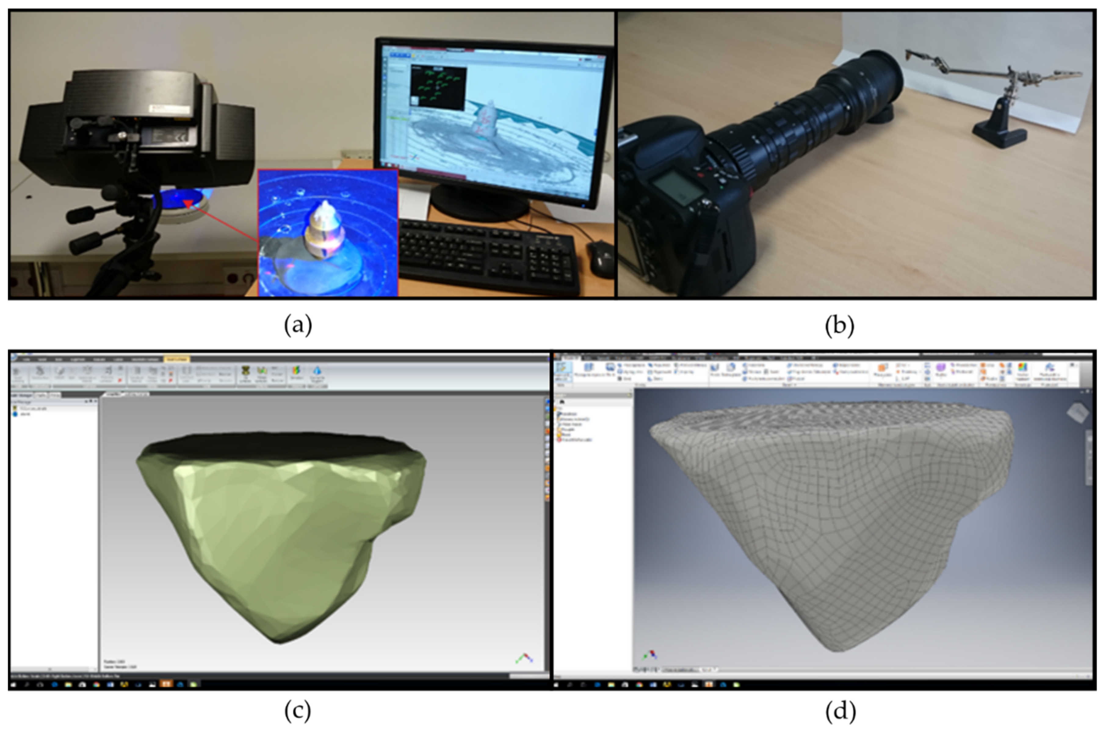
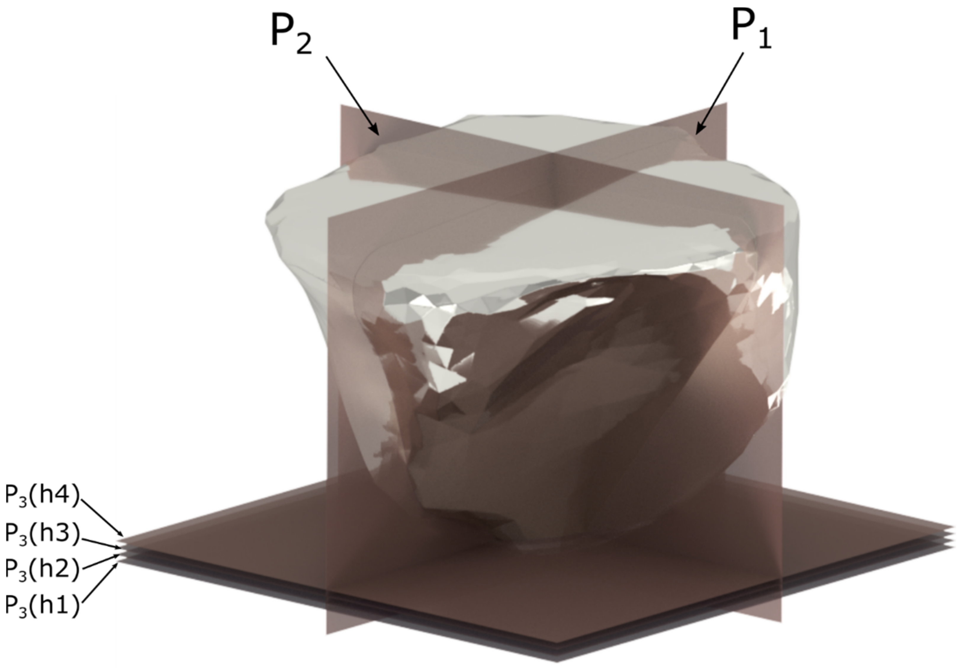
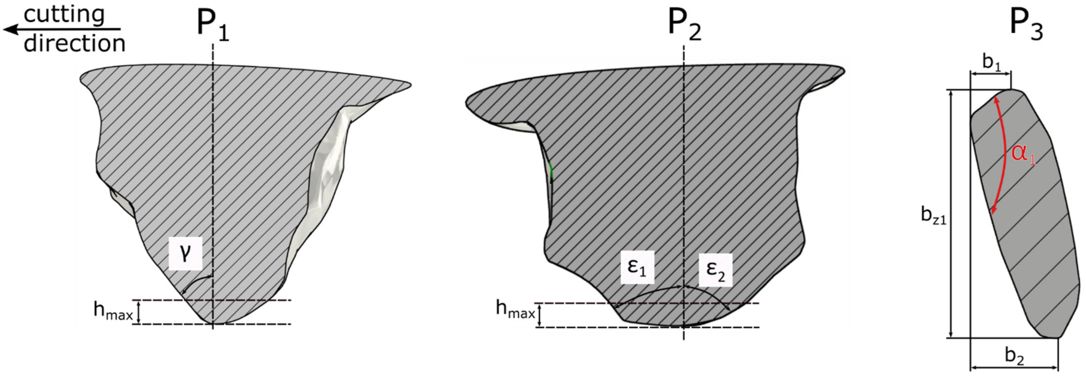
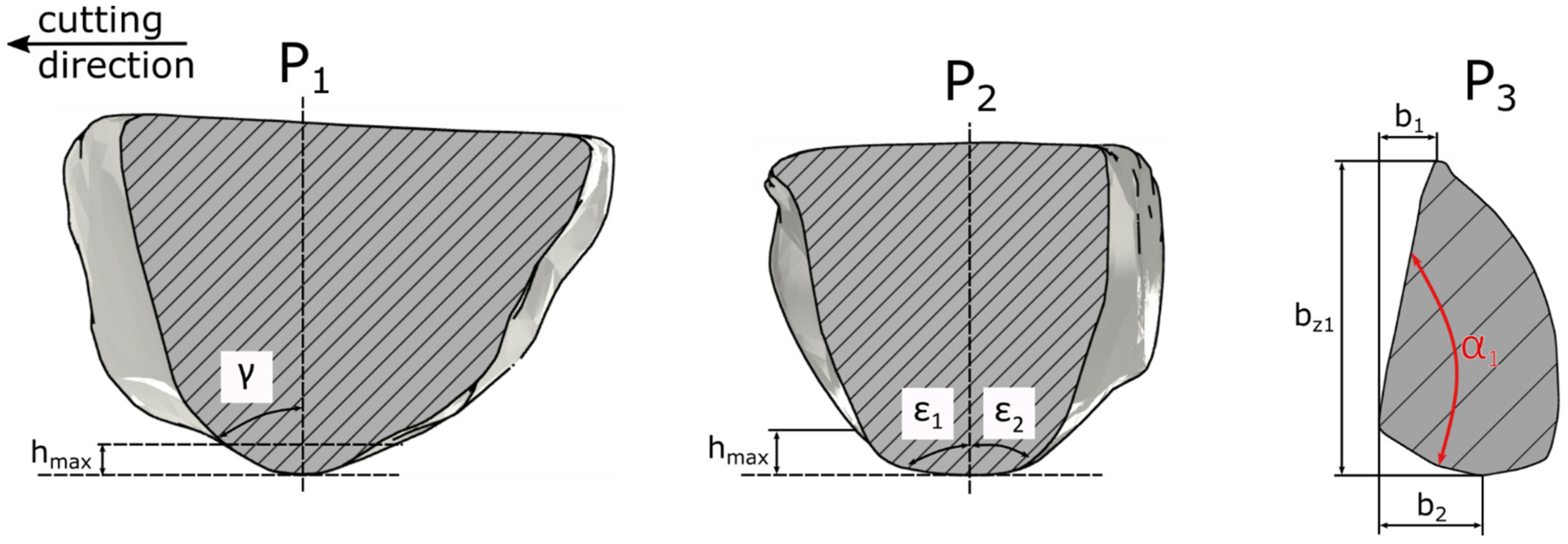
2.3. Methodology for Evaluating the Geometrical Characteristics of Abrasive Grains
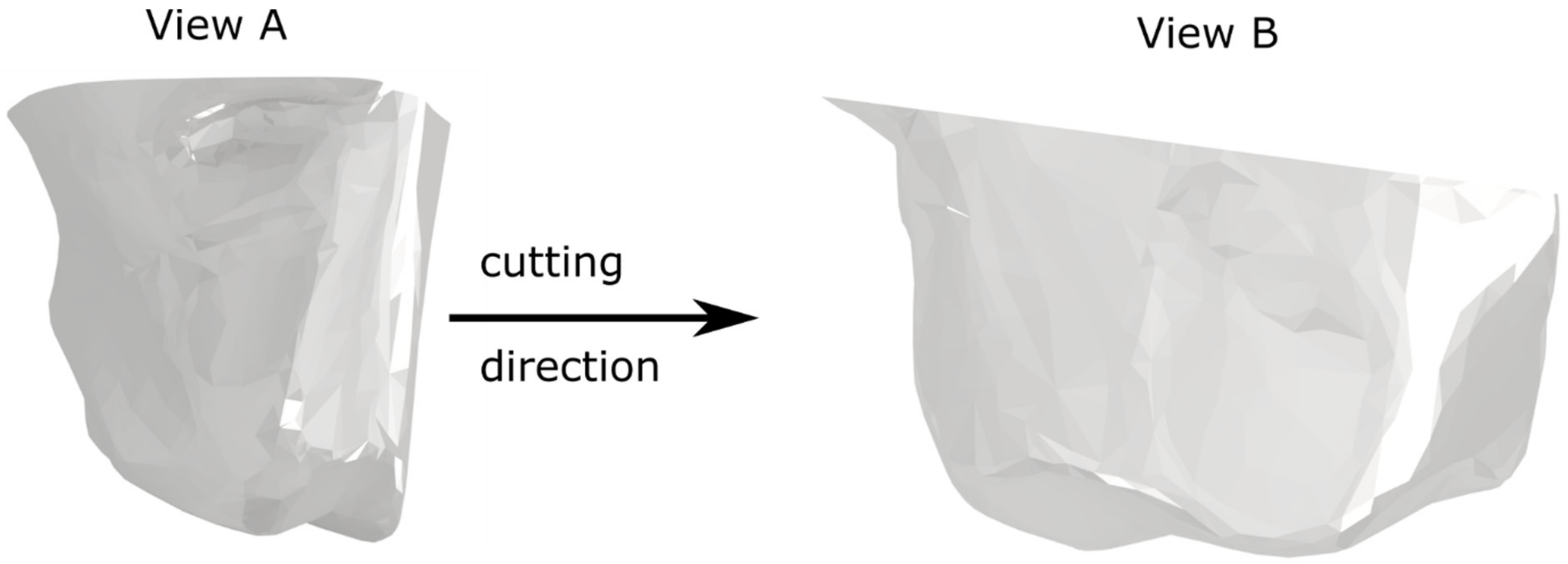
Analysis of the Geometrical Features of the Abrasive Grain
3. Results and Discussion
3.1. Experimental Validation of Computer Models
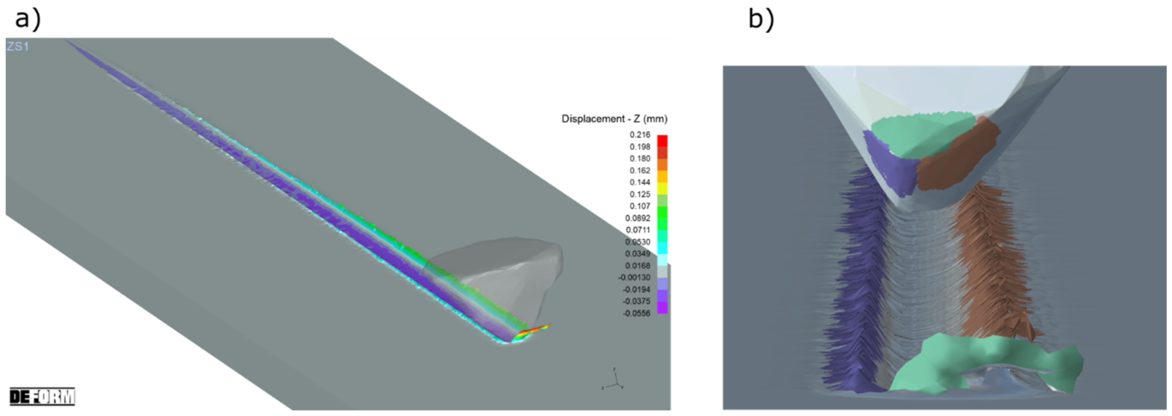
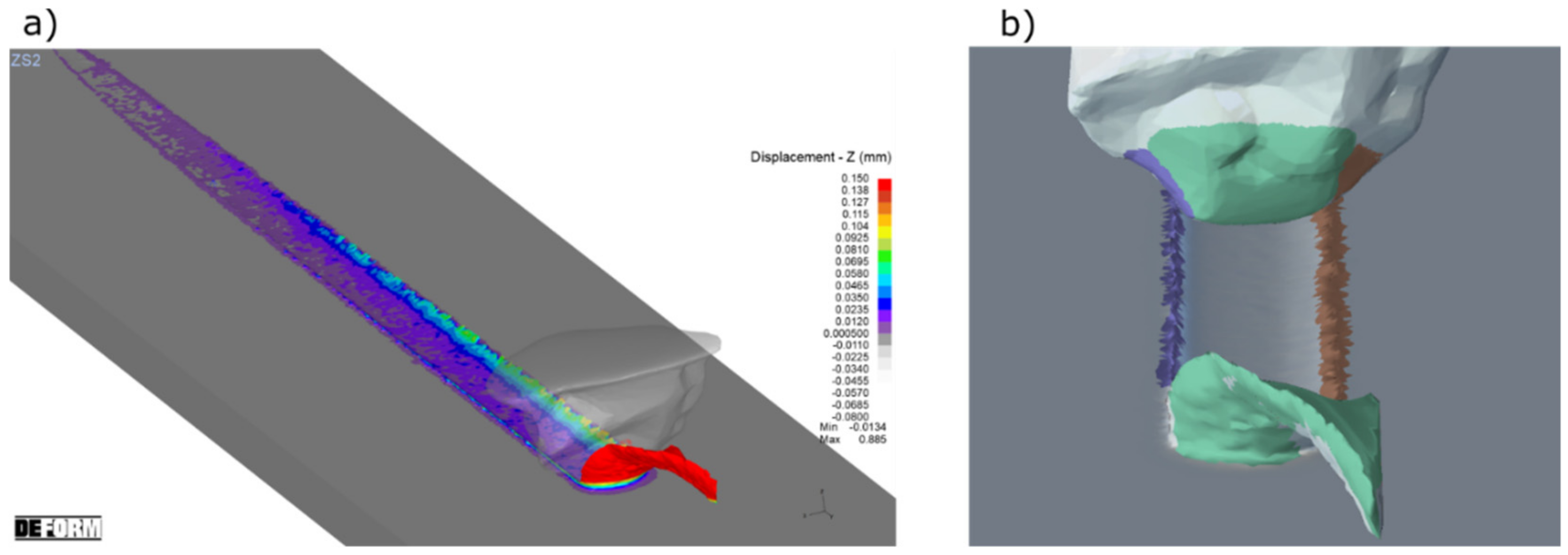
3.2. The Analysis of Material Removal Process by the Grains with Different Shapes
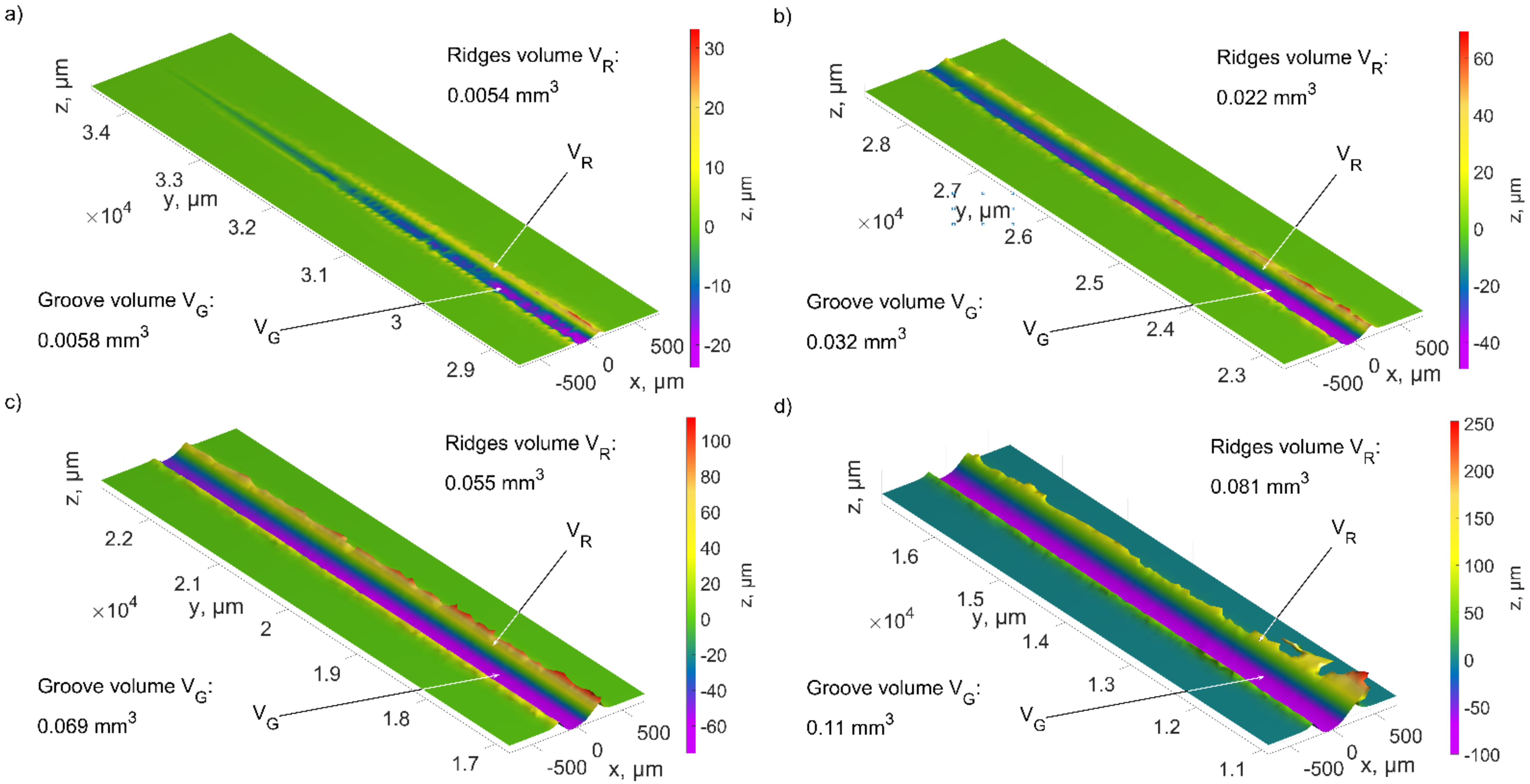
3.3. The Analysis of the Geometrical Features of the Abrasive Grain on the Efficiency of Material Removal
- The ratio of the rake angle γ to the apex angle ε of the abrasive grain;
- The ratio of the length of the cutting zone bb (the path that the material moves to the sides of the abrasive grain) to the width of the cutting zone bz;
- The opening angle α of the abrasive grain;
4. Conclusions
- Modeling of the cutting process with a single abrasive grain using FEM enabled the analysis of lateral ridges and chip formation process in the cutting with a single abrasive grain.
- Based on the value of the bb/bz ratio, it can be concluded that if: bb/bz < 1, the material will be removed in the form of a chip with a large width, small-volume ridges will be produced, the cutting efficiency will be high; if bb/bz = 1, the material will be removed in the form of a chip with a small width, there will be lateral ridges of considerable volume; if bb/bz > 1, a small volume of chip should be expected, large-volume ridges will be produced, and the cutting efficiency will be low.
- The opening angle α of the abrasive grain allowed to assess the effectiveness of material removal. A small opening angle α of up to 60° resulted in increased lateral material flows and thus low cutting efficiency. With large opening angles of 120–180°, the material was deposited as a wide chip, significantly increasing the efficiency of the material removal process.
- The developed models of the relationship between the geometrical parameters of the cutting blades (rake angle γ, apex angle ε, opening angle α, width bz and the length of the cutting zone bb) allowed us to determine the material removal efficiency for abrasive grains with different geometries.
Author Contributions
Funding
Institutional Review Board Statement
Informed Consent Statement
Data Availability Statement
Conflicts of Interest
References
- Wang, T.; Zou, L.; Li, H.; Huang, Y. A prediction model of residual stress for belt-grinding blade based on geometrical characteristic and progressive wear of abrasive grains. Int. J. Numer. Methods Eng. 2022, 123, 2814–2836. [Google Scholar] [CrossRef]
- Lipiński, D.; Kacalak, W.; Bałasz, B. Optimization of sequential grinding process in a fuzzy environment using genetic algorithms. J. Braz. Soc. Mech. Sci. Eng. 2019, 41, 96. [Google Scholar] [CrossRef]
- Arrazola, P.J.; Özel, T. Investigations on the effects of friction modeling in finite element simulation of machining. Int. J. Mech. Sci. 2010, 52, 31–42. [Google Scholar] [CrossRef]
- Ezugwu, E.O. Key improvements in the machining of difficult-to-cut aerospace superalloys. Int. J. Mach. Tool Manufact. 2005, 45, 1353–1367. [Google Scholar] [CrossRef]
- Mohammadali, K.; Bahman, A.; Sergey, S.; Peter, K. The effect of dressing parameters on micro-grinding of titanium alloy. Precis. Eng. 2018, 51, 176–185. [Google Scholar]
- Li, X.; Ma, S.; Meng, F.J. Surface integrity of GH4169 affected by cantilever finish grinding and the application in aero-engine blades. Chin. J. Aeronaut. 2015, 28, 1539–1545. [Google Scholar] [CrossRef]
- Chen, X.; Öpöz, T.T.; Oluwajobi, A. Analysis of grinding surface creation by single-grit approach. J. Manuf. Sci. Eng. 2017, 139, 121007. [Google Scholar] [CrossRef]
- Anderson, D.; Warkentin, A.; Bauer, R. Novel Experimental Method to Determine the Cutting Effectiveness of Grinding Grits. Exp. Mech. 2011, 51, 1535–1543. [Google Scholar] [CrossRef]
- Merchant, M.E. Mechanics of the Metal Cutting Process. I. Orthogonal Cutting and a Type 2 Chip. J. Appl. Phys. 1945, 16, 267–275. [Google Scholar] [CrossRef]
- Merchant, M.E. Mechanics of the Metal Cutting Process. II. Plasticity Conditions in Orthogonal Cutting. J. Appl. Phys. 1945, 16, 318–324. [Google Scholar] [CrossRef]
- Nakayama, K.; Arai, M. Comprehensive chip form classification based on the cutting mechanism. Ann. CIRP 1992, 41, 71–74. [Google Scholar] [CrossRef]
- Malkin, S.; Lenz, E. Negative rake cutting to simulate chip formation in grinding. Ann. CIRP 1979, 28, 209–212. [Google Scholar]
- Rasim, M.; Mattfeld, P.; Klocke, F. Analysis of the grain shape influence on the chip formation in grinding. J. Mater. Process. Technol. 2015, 226, 60–68. [Google Scholar] [CrossRef]
- Yuan, X.; Wang, C.; Sun, Q.; Zhao, L. Numerical and Experimental Research on the Brushing Aluminium Alloy Mechanism Using an Abrasive Filament Brush. Materials 2021, 14, 6647. [Google Scholar] [CrossRef]
- Rypina, Ł.; Lipiński, D.; Bałasz, B.; Kacalak, W.; Szatkiewicz, T. Analysis and Modeling of the Micro-Cutting Process of Ti-6Al-4V Titanium Alloy with Single Abrasive Grain. Materials 2020, 13, 5835. [Google Scholar] [CrossRef] [PubMed]
- Doman, D.A.; Warkentin, A.; Bauer, R. Finite element modelling approaches in grinding. Int. J. Mach. Tools Manuf. 2009, 49, 109–116. [Google Scholar] [CrossRef]
- Doman, D.A.; Warkentin, A.; Bauer, R. Experimentally validated finite element model of the rubbing and ploughing phases in scratch test. J. Mach. Tools Manuf. 2009, 223, 1519–1527. [Google Scholar] [CrossRef]
- Zhao, B.; Jiang, G.; Ding, W.; Xiao, G.; Huan, H.; Wang, Y.; Su, H. Characterisation of the wear properties of a single-aggregated cubic boron nitride grain during Ti–6Al–4V alloy grinding. Wear 2020, 452–453, 203296. [Google Scholar] [CrossRef]
- Zhao, B.; Ding, W.; Zhou, Y.; Su, H.; Xu, J. Effect of grain wear on material removal behaviour during grinding of Ti-6Al-4V titanium alloy with single aggregated cBN grain. Ceram. Int. Vol. 2019, 45, 14842–14850. [Google Scholar] [CrossRef]
- Dai, C.; Yu, T.; Ding, W.; Xu, J.; Yin, Z.; Li, H. Single diamond grain cutting-edges morphology effect on grinding mechanism of Inconel 718. Precis. Eng. 2019, 55, 119–126. [Google Scholar] [CrossRef]
- Xie, Y.; Williams, J.A. The generation of worn surfaces by the repeated interaction of parallel grooves. Wear 1993, 162–164 Pt B, 864–872. [Google Scholar] [CrossRef]
- Axinte, D.; Butler-Smith, P.; Akgun, C.; Kolluru, K. On the influence of single grit micro-geometry on grinding behavior of ductile and brittle materials. Int. J. Mach. Tools Manuf. 2013, 74, 12–18. [Google Scholar] [CrossRef]
- Karkalos, N.E.; Markopoulos, A.P. Molecular Dynamics Study of the Effect of Abrasive Grains Orientation and Spacing during Nanogrinding. Micromachines 2020, 11, 712. [Google Scholar] [CrossRef]
- Gao, Y.; Wang, F.; Liang, Y.; Han, J.; Su, J.; Tong, Y.; Liu, L. Cutting Performance of Randomly Distributed Active Abrasive Grains in Gear Honing Process. Micromachines 2021, 12, 1119. [Google Scholar] [CrossRef] [PubMed]
- Johnson Cook, W.H. A constitutive model and data for metals subjected to large strains, high strain rates and high temperatures. In Proceedings of the Seventh International Symposium on Ballistics, The Hague, The Netherlands, 19–21 April 1983; pp. 541–547. [Google Scholar]
- Lee, W.; Lin, C. High-temperature deformation behaviour of Ti6A14V alloy evaluated by high strain-rate compression tests. J. Mater. Process. Technol. 1998, 75, 127–136. [Google Scholar] [CrossRef]
- Umbrello, D. Finite element simulation of conventional and high speed machining of Ti6Al4V alloy. J. Mater. Process. Technol. 2008, 196, 79–87. [Google Scholar] [CrossRef]
- Sima, M.; Özel, T. Modified material constitutive models for serrated chip formation simulations and experimental validation in machining of titanium alloy Ti-6Al-4V. Int. J. Mach. Tools Manuf. 2010, 50, 943–960. [Google Scholar] [CrossRef]
- Cockroft, M.D.; Latham, D.J. Ductility and the workability of metals. J. Inst. Met. 1968, 96, 33–39. [Google Scholar]
- Alexandrov, S.; Jeng, Y.-R. An efficient method for the identification of the modified Cockroft–Latham fracture criterion at elevated temperature. Arch. Appl. Mech. 2013, 83, 1801–1804. [Google Scholar] [CrossRef]
- Gocmen, A.; Sartkulvanich, P.; Altan, T. Effects of flow stress and friction models in finite element simulation of orthogonal cutting a sensitivity analysis. Mach. Sci. Technol. 2005, 9, 1–26. [Google Scholar]
- Astakhov, V.P.; Outeiro, J.C. Modeling of the contact stress distribution at the tool–chip interface. Mach. Sci. Technol. 2005, 9, 85–99. [Google Scholar] [CrossRef]
- Özel, T. The influence of friction models on finite element simulations of machining. Int. J. Mach. Tools Manuf. 2006, 46, 518–530. [Google Scholar] [CrossRef]
- DEFORM. v12sp2 System Documentation; Scientific Forming Technologies Corporation: Columbus, OH, USA, 2 July 2020. [Google Scholar]
- Kacalak, W.; Lipiński, D.; Szafraniec, F.; Zawada-Tomkiewicz, A.; Tandecka, K.; Królczyk, G. Metrological basis for assessing the state of the active surface of abrasive tools based on parameters characterising their machining potential. Measurement 2020, 165, 108068. [Google Scholar] [CrossRef]


| Material | A, MPa | B, MPa | C | n | M |
|---|---|---|---|---|---|
| Ti-6Al-4V | 782.7 | 498.4 | 0.028 | 0.28 | 1.0 |
| Grain | Depth of Cut | b1 [mm] | b2 [mm] | bz1 [mm] | γ [°] | ε1 [°] | ε2 [°] | α [°] | |
|---|---|---|---|---|---|---|---|---|---|
| ZS1 | h1 | 0.20 | 0.33 | 0.19 | 2.79 | −81 | 78 | 74 | 41 |
| h2 | 0.23 | 0.50 | 0.26 | 2.81 | −74 | 63 | 40 | 44 | |
| h3 | 0.27 | 0.54 | 0.31 | 2.61 | −70 | 57 | 39 | 46 | |
| h4 | 0.30 | 0.51 | 0.36 | 2.25 | −54 | 54 | 40 | 50 | |
| ZS2 | h1 | 0.09 | 0.19 | 0.56 | 0.50 | −68 | 84 | 84 | 128 |
| h2 | 0.11 | 0.19 | 0.71 | 0.42 | −48 | 78 | 77 | 135 | |
| h3 | 0.09 | 0.21 | 0.79 | 0.38 | −47 | 37 | 73 | 139 | |
| h4 | 0.12 | 0.24 | 0.86 | 0.42 | −42 | 37 | 61 | 135 | |
| ZS3 | h1 | 0.10 | 0.16 | 0.50 | 0.52 | −82 | 83 | 81 | 126 |
| h2 | 0.13 | 0.30 | 0.60 | 0.72 | −64 | 78 | 59 | 112 | |
| h3 | 0.20 | 0.36 | 0.69 | 0.81 | −61 | 59 | 49 | 104 | |
| h4 | 0.19 | 0.41 | 0.74 | 0.81 | −60 | 47 | 48 | 105 |
Publisher’s Note: MDPI stays neutral with regard to jurisdictional claims in published maps and institutional affiliations. |
© 2022 by the authors. Licensee MDPI, Basel, Switzerland. This article is an open access article distributed under the terms and conditions of the Creative Commons Attribution (CC BY) license (https://creativecommons.org/licenses/by/4.0/).
Share and Cite
Rypina, Ł.; Lipiński, D.; Banaszek, K.; Kacalak, W.; Szafraniec, F. Influence of the Geometrical Features of the Cutting Edges of Abrasive Grains on the Removal Efficiency of the Ti6Al4V Titanium Alloy. Materials 2022, 15, 6189. https://0-doi-org.brum.beds.ac.uk/10.3390/ma15186189
Rypina Ł, Lipiński D, Banaszek K, Kacalak W, Szafraniec F. Influence of the Geometrical Features of the Cutting Edges of Abrasive Grains on the Removal Efficiency of the Ti6Al4V Titanium Alloy. Materials. 2022; 15(18):6189. https://0-doi-org.brum.beds.ac.uk/10.3390/ma15186189
Chicago/Turabian StyleRypina, Łukasz, Dariusz Lipiński, Kamil Banaszek, Wojciech Kacalak, and Filip Szafraniec. 2022. "Influence of the Geometrical Features of the Cutting Edges of Abrasive Grains on the Removal Efficiency of the Ti6Al4V Titanium Alloy" Materials 15, no. 18: 6189. https://0-doi-org.brum.beds.ac.uk/10.3390/ma15186189