
Review of Modeling Techniques for Analysis and Assessment of RC Beam–Column Joints Subjected to Seismic Loads
 , , , , ,
  , and
, and 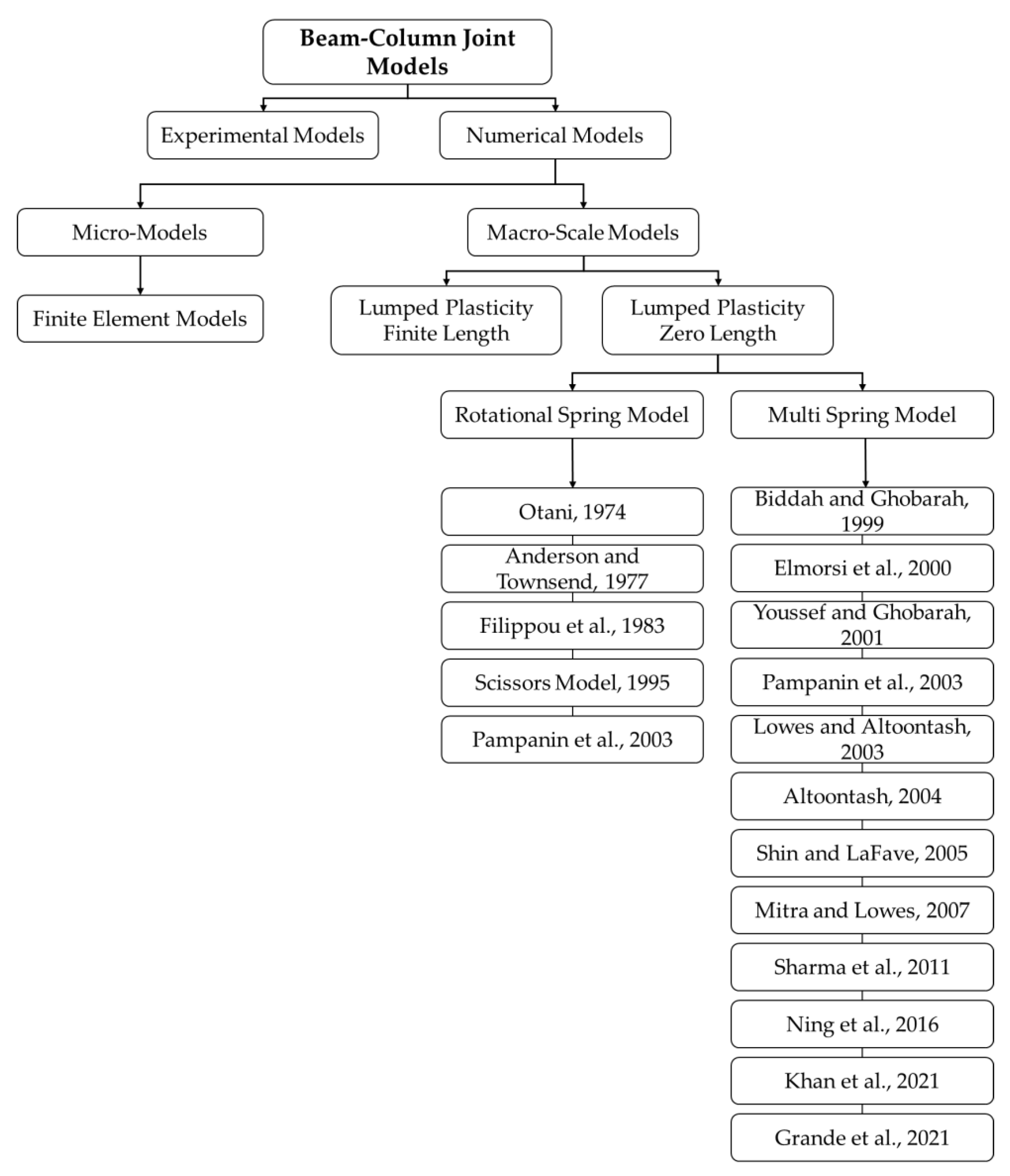
Abstract
:1. Introduction
1.1. Research Impact
1.2. Experimental Models
1.3. Analytical Models
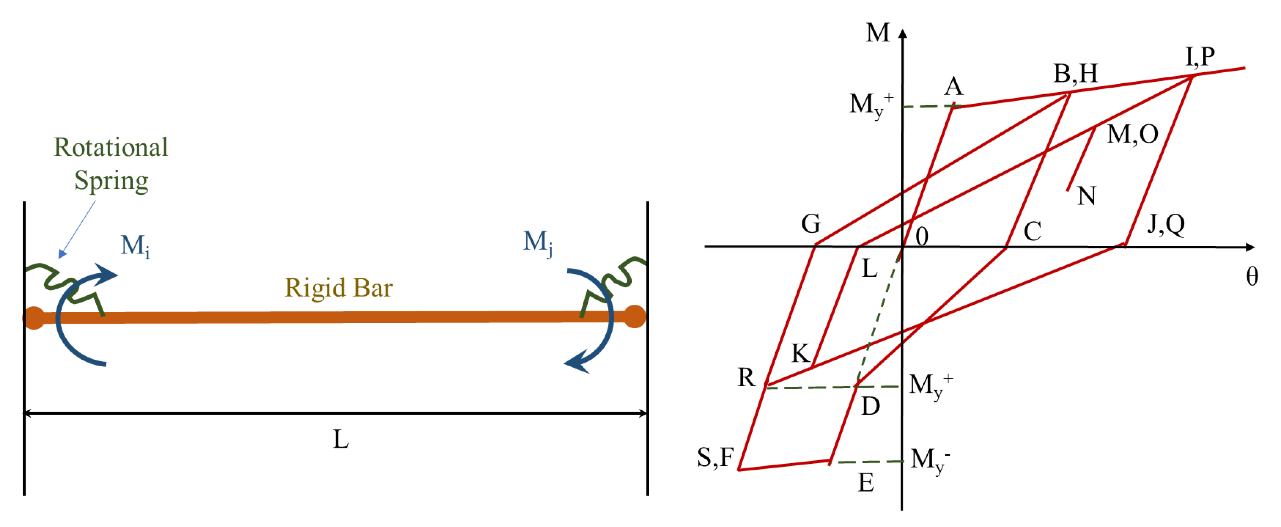
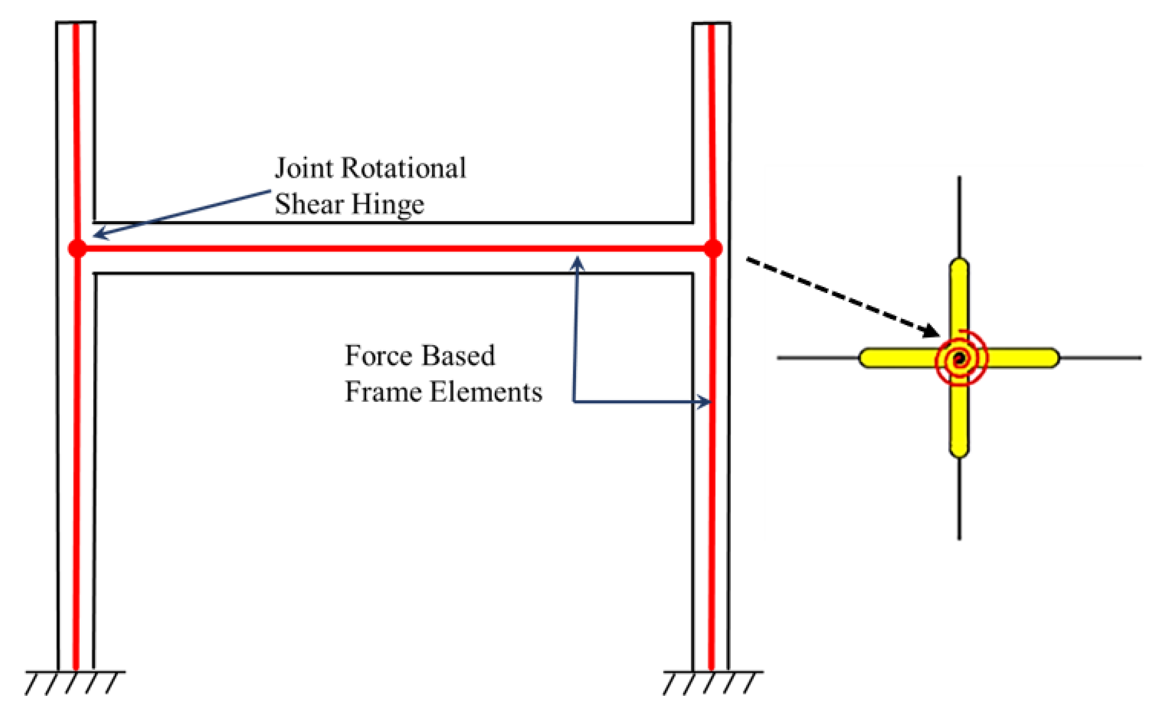
1.3.1. Rotational Hinge Models
Summary of Rotational Spring Models
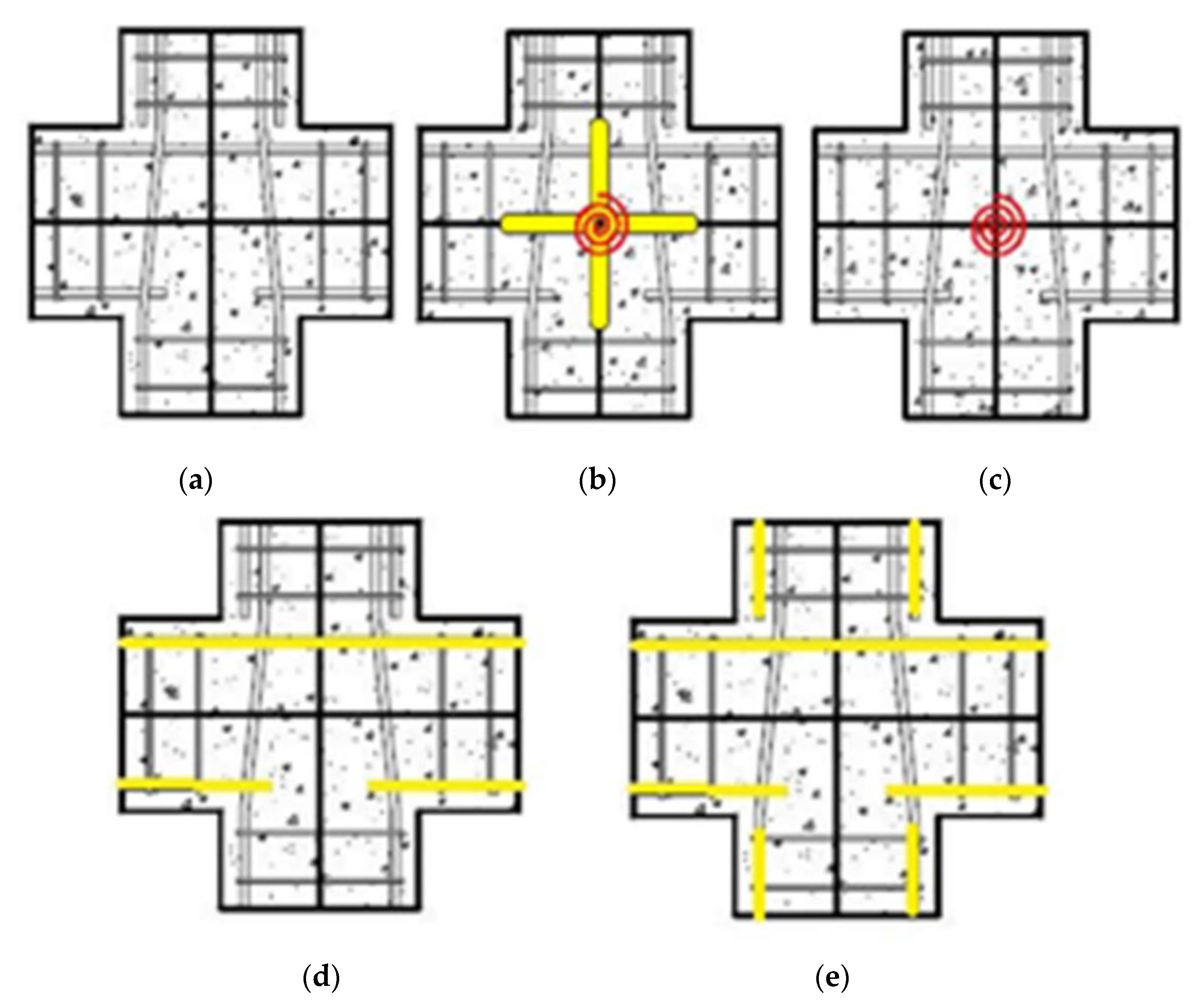
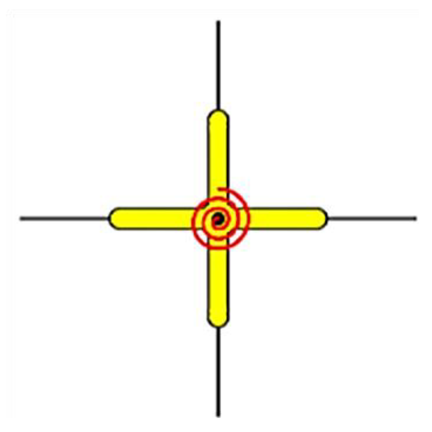
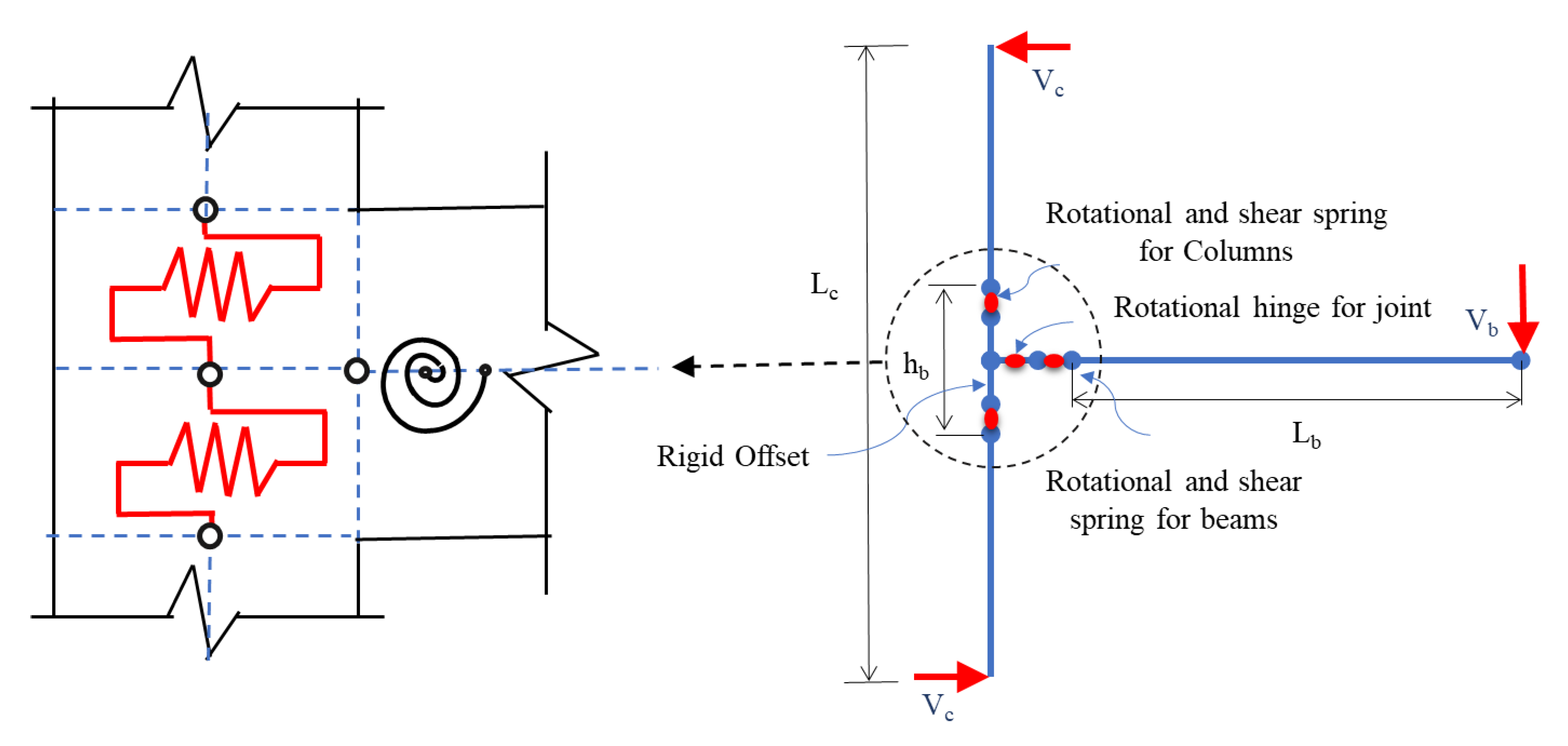
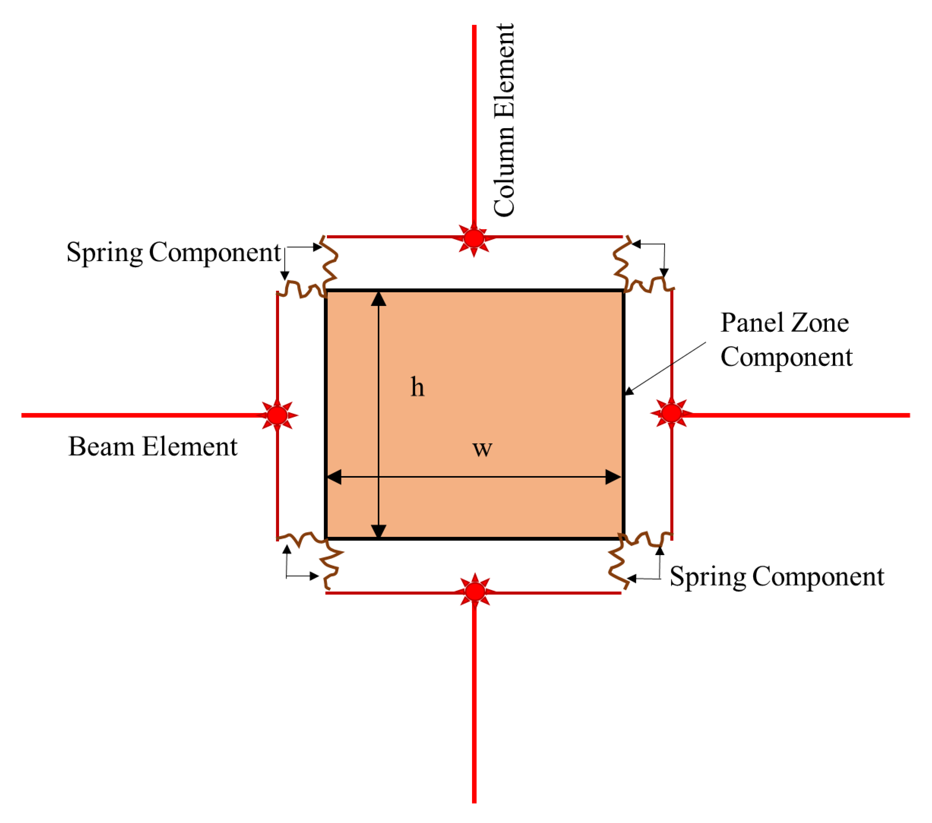
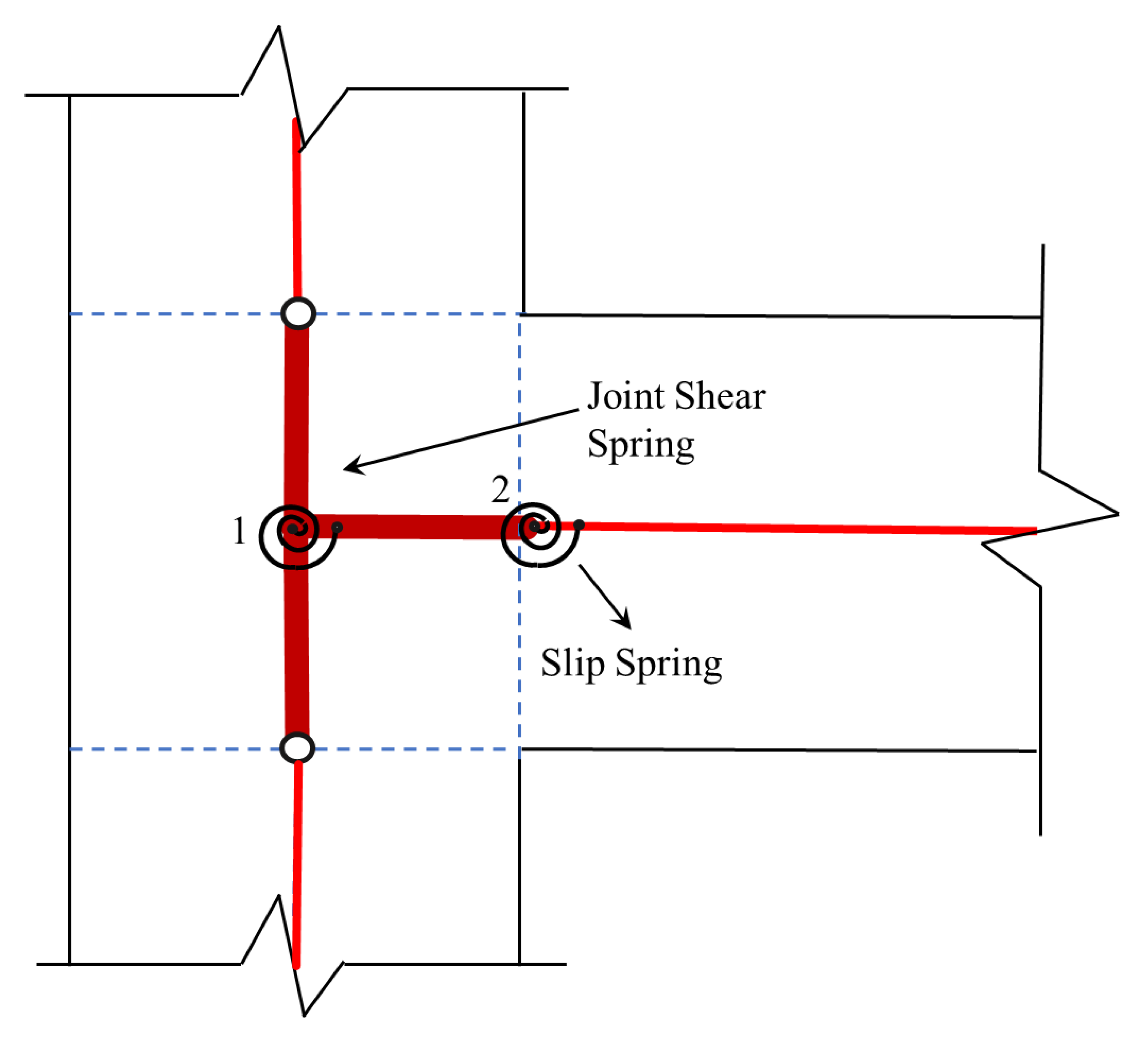
1.3.2. Multi-Spring Models
- They necessitate a greater computational effort than rotating hinge models.
- They frequently necessitate the inclusion of a unique feature in software.
- Most available models are incompatible with gravity-designed frame joints.
1.4. Lumped-Plasticity Approach
Spread Plasticity Approach
1.5. Finite Element (FE) Numerical Modeling
2. Conclusions
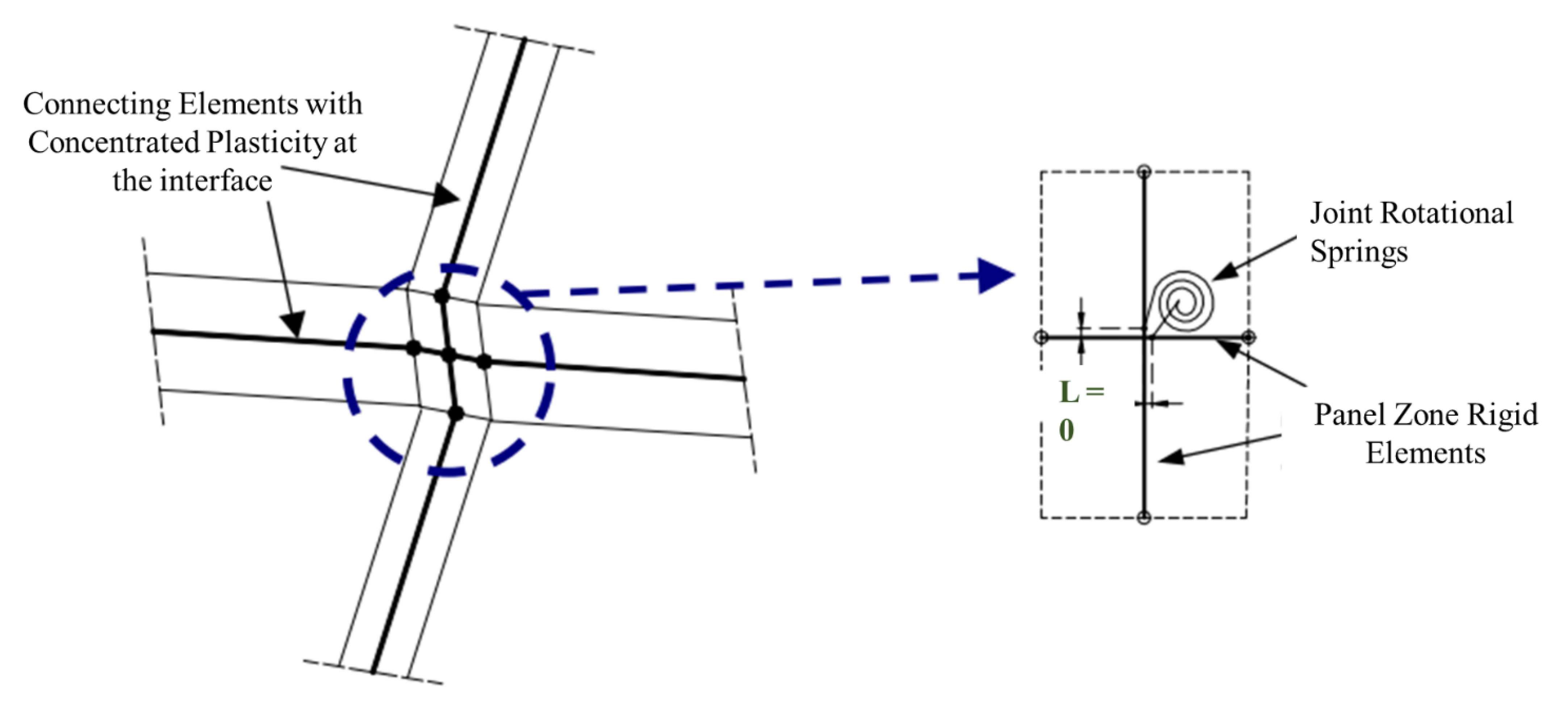
- In rotational spring models, a central zero-length element is used to connect the elastic beams and columns to the joint. The entire non-linear behavior is lumped in a single rotational spring, due to which, it is difficult to individually assess the joint panel shear, interface shear, and bar–slip mechanism.
- -
- In this scenario, determining the M-θ properties necessitates extensive experimental data for the calibration and validation of the model.
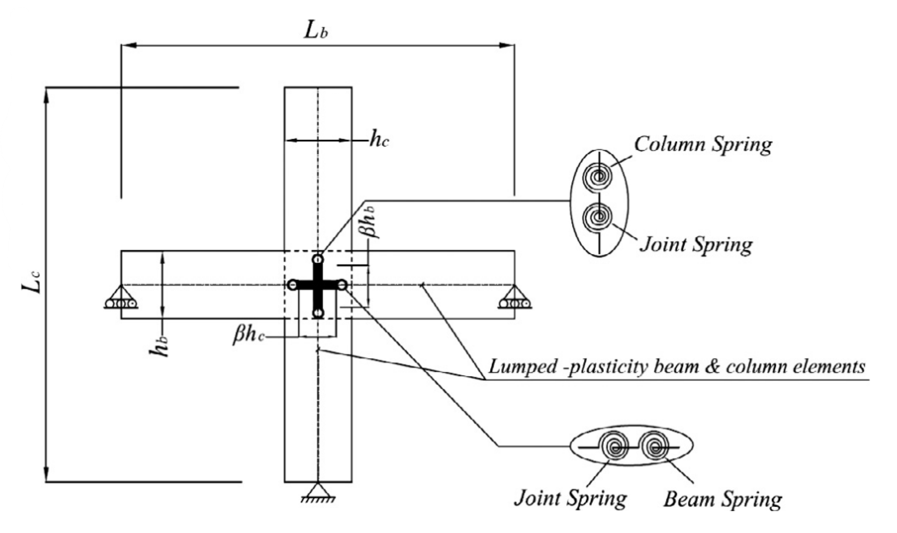
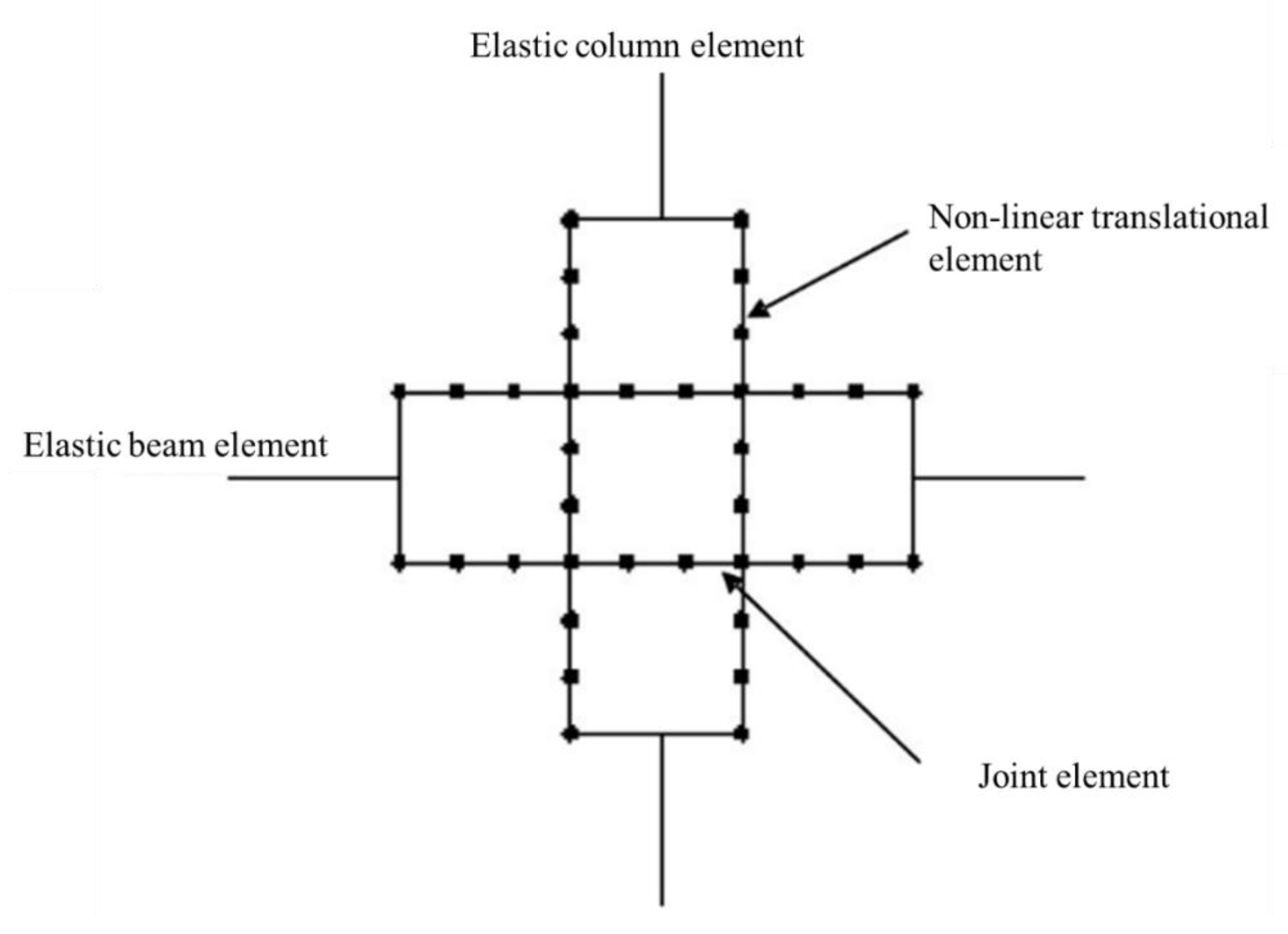
- A much more realistic and widely accepted approach is the multi-spring modeling technique, as it captures the individual responses using separate springs for each joint mechanism and is applicable to the analysis or assessment of entire structures.
- -
- The behavior is presented through non-linear translational or rotational springs.
- -
- With these models, more accurate and realistic simulation results can be obtained with a slight increase in computational effort, and computer memory requirements are compared to lumped plasticity or rotational spring approaches.
- -
- The computational effort and computer memory demand is still significantly low compared to the FE model.
- -
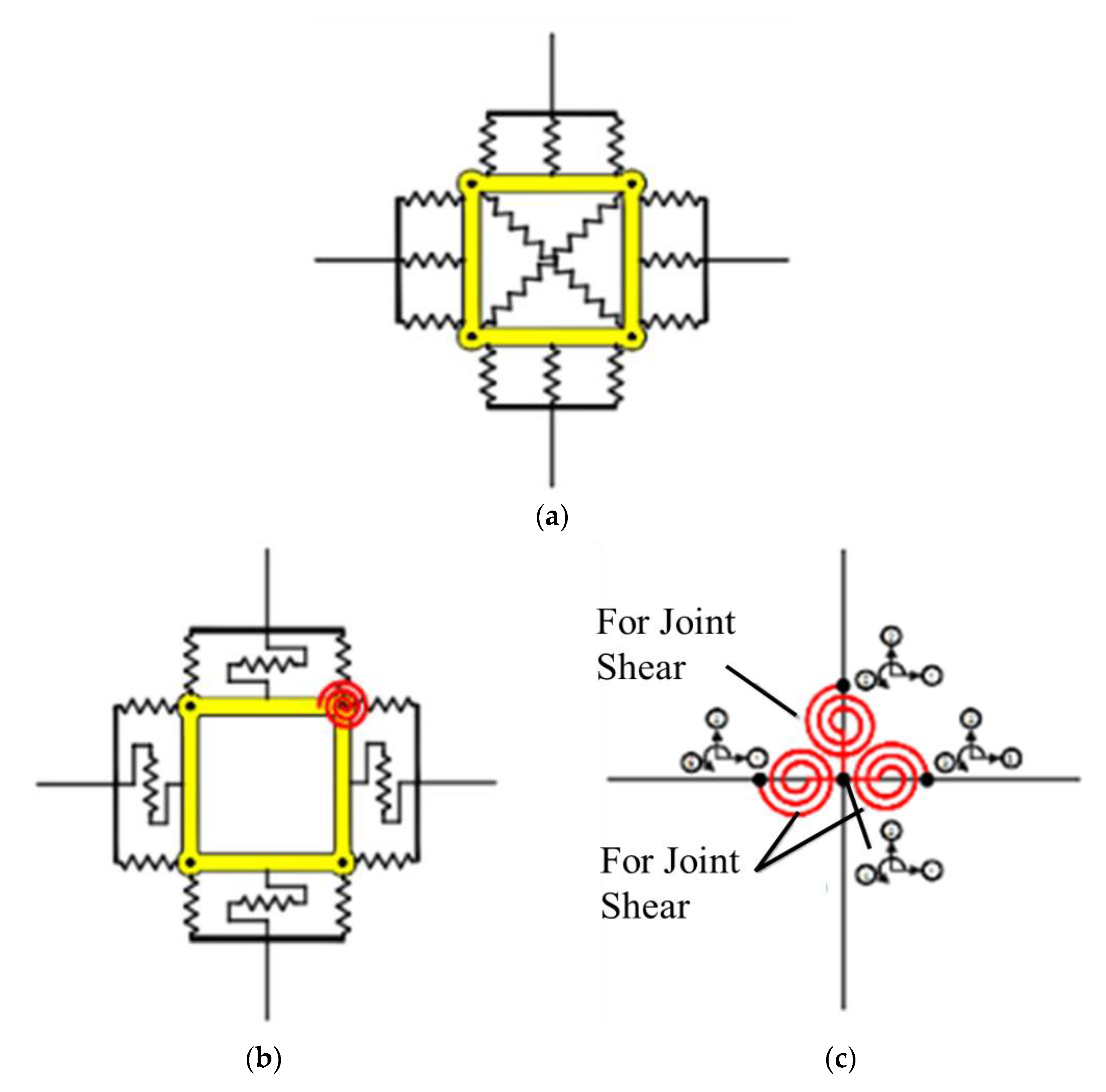
- However, a separate material and constitutive model needs to be assigned to each zero-length spring/hinge for governing its non-linear response.
- -
- Several multi-spring models are not suitable for RC frames without shear reinforcement in the joint core, which is a more critical deficiency in gravity-designed frames.
- -
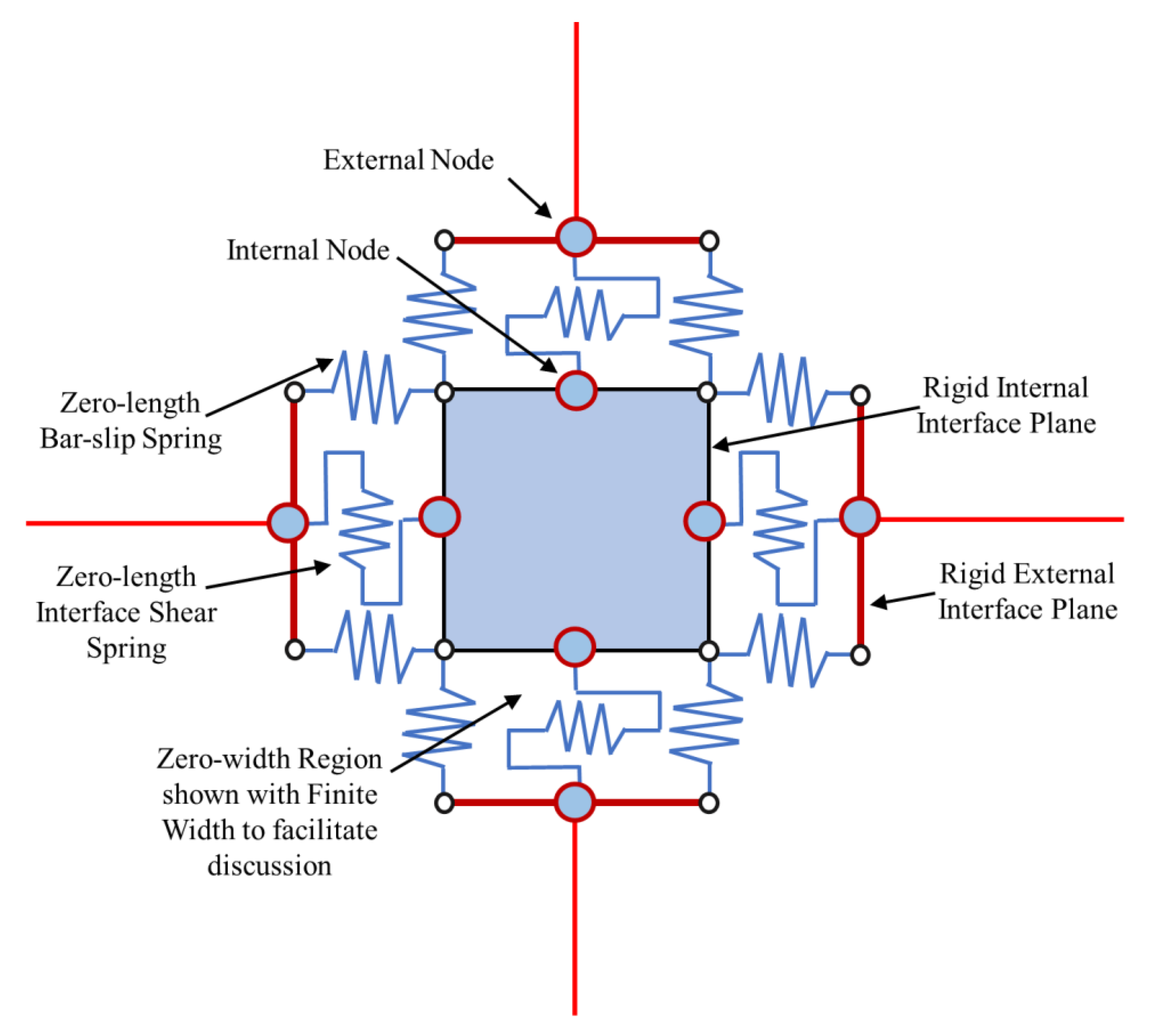
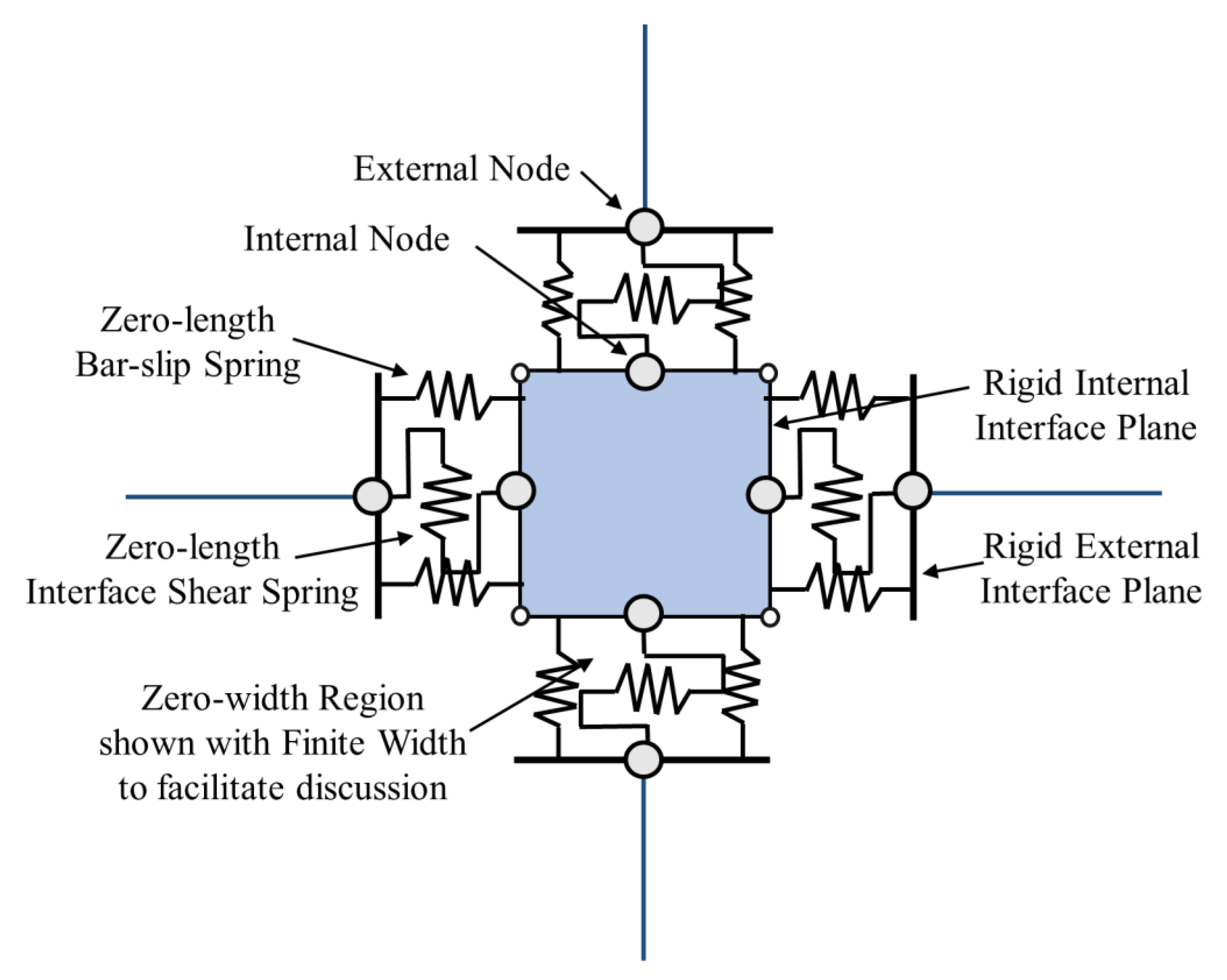
- The most accurate approximation is carried out by using the model by Lowes et al., 2007, as it covers almost all of the mechanisms individually through linear and rotational springs. However, the computational effort is significantly increased.
- -
- The scissors model is the simplest, with minimal computational effort. However, only the joint panel rotation is captured. The bar–slip mechanism at the interface is not considered.
- -
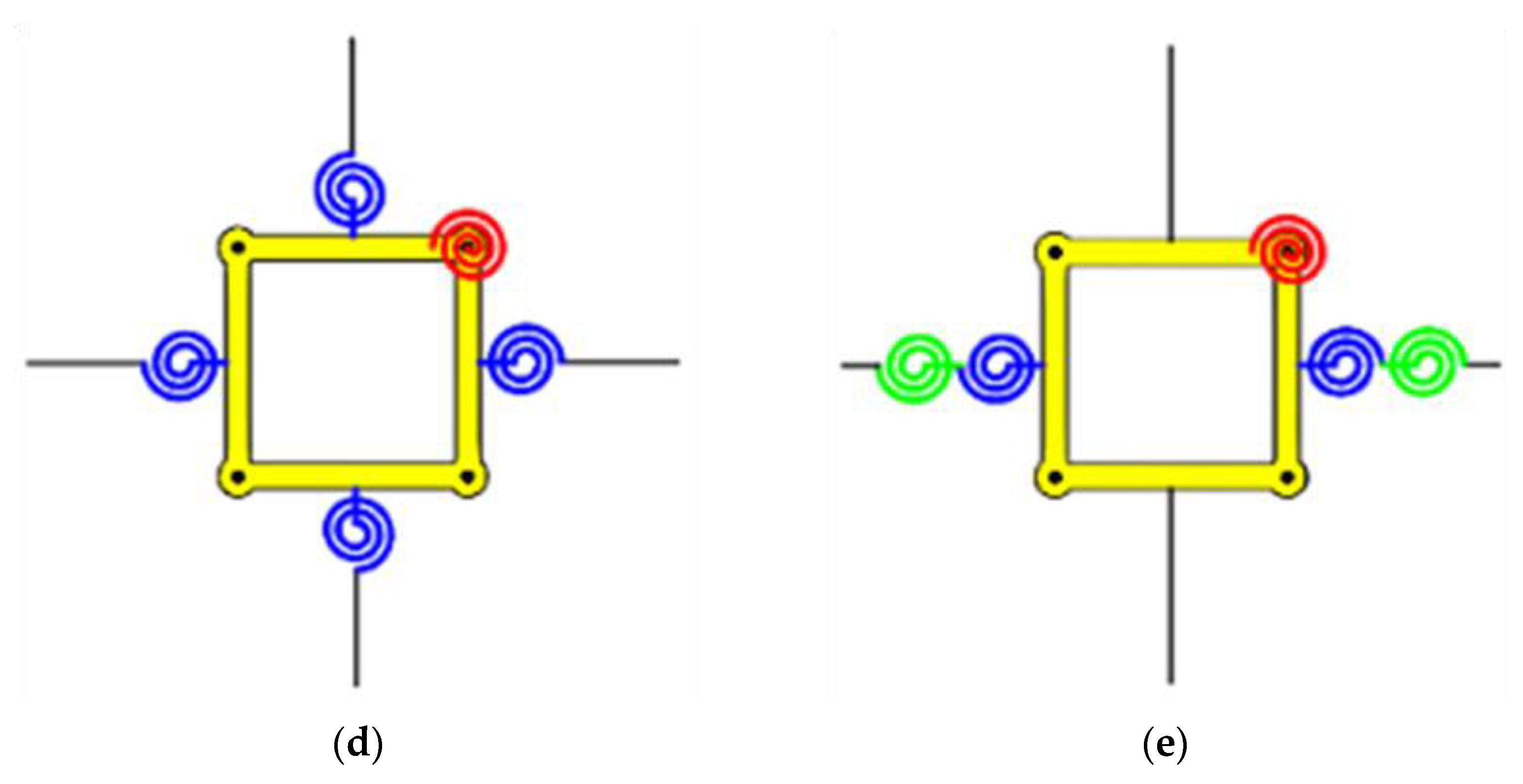
- In multi-spring models, the model by Grande et al. can be considered as the most efficient in terms of both the accuracy and computational effort. Both the interface and joint panel response have been covered efficiently using two springs. The fact that the bar–slip mechanism is more critical at the beam–joint interface is effectively used to minimize the computational effort.
Author Contributions
Funding
Institutional Review Board Statement
Informed Consent Statement
Data Availability Statement
Acknowledgments
Conflicts of Interest
References
- Pantazopoulou, S.J.; Bonacci, J.F. On earthquake-resistant reinforced concrete frame connections. Can. J. Civ. Eng. 1994, 21, 307–328. [Google Scholar] [CrossRef]
- Genesio, G.; Sharma, A.; Eligehausen, R.; Pampanin, S.; Reddy, G.R.; Vaze, K.K. Experimental Investigations on Seismic Retrofitting of Reinforced Concrete Beam-Column Joints. In Proceedings of the 14th Symposium on Earthquake Engineering, Roorkee, India, 17–19 December 2010. [Google Scholar]
- Alath, S. Modeling Inelastic Shear Deformation in Reinforced Concrete Beam-Column Joints. Retrospective Theses and Dissertations. Master’s Thesis, College of Engineering, University of Central Florida, Orlando, FL, USA, January 1995. Available online: https://stars.library.ucf.edu/rtd/3135 (accessed on 12 April 2022).
- Sadjadi, R.; Kianoush, M.R. Effect of Modeling Features on Response of Reinforced Concrete Frames. In Proceedings of the 3th World Conference on Earthquake Engineering, Vancouver, BC, Canada, 1–6 August 2004. [Google Scholar]
- Biddah, A.; Ghobarah, A. Modelling of shear deformation and bond slip in reinforced concrete joints. Struct. Eng. Mech. 1999, 7, 413–432. [Google Scholar] [CrossRef]
- Li, B.; Kai, Q.; Xue, W. Effects of Eccentricity on the Seismic Rehabilitation Performance of Nonseismically Detailed Interior Beamwide Column Joints. J. Compos. Constr. 2012, 16, 507–519. [Google Scholar] [CrossRef]
- Grande, E.; Imbimbo, M.; Napoli, A.; Nitiffi, R.; Realfonzo, R. A Nonlinear Macro-Model for the Analysis of Monotonic and Cyclic Behaviour of Exterior RC Beam-Column Joints. Front. Mater. 2021, 8, 289. [Google Scholar] [CrossRef]
- Khan, M.S.; Basit, A.; Ahmad, N. A simplified model for inelastic seismic analysis of RC frame have shear hinge in beam-column joints. Structures 2021, 29, 771–784. [Google Scholar] [CrossRef]
- Townsend, W.H.; Hanson, R.D. Hysteresis loops for reinforced concrete beam-column connections. In Proceedings of the 5th World Conference on Earthquake Engineering, Rome, Italy, 25–29 June 1973; Volume 1, pp. 1131–1134. [Google Scholar]
- Anderson, J.C.; Townsend, W.H. Models for RC Frames with Degrading Stiffness. J. Struct. Div. 1977, 103, 2361–2376. [Google Scholar] [CrossRef]
- Soleimani, D.; Popov, E.P.; Bertero, V.V. Hysteretic Behavior of Reinforced Concrete Beam-Column Subassemblages. ACI J. Proc. 1979, 76, 1179–1196. [Google Scholar] [CrossRef]
- Giberson, M.F. Two Nonlinear Beams with Definitions of Ductility. J. Struct. Div. ASCE 1969, 95, 137–157. [Google Scholar] [CrossRef]
- Otani, S. Nonlinear dynamic analysis of reinforced concrete building structures. Can. J. Civ. Eng. 1980, 7, 333–344. [Google Scholar] [CrossRef]
- Takeda, T.; Sozen, M.A.; Nielsen, N.N. Reinforced Concrete Response to Simulated Earthquakes. J. Struct. Div. 1970, 96, 2557–2573. [Google Scholar] [CrossRef]
- Banon, H.; Biggs, J.M.; Irvine, H.M. Seismic Damage in Reinforced Concrete Frames. J. Struct. Div. 1981, 107, 1713–1729. [Google Scholar] [CrossRef]
- Alva, G.M.S.; Canha, R.M.F.; Filho, J.O.; El Debs, A.L. Numerical model for analysis of reinforced concrete beams under repeated cyclic loads. Numerical model for analysis of reinforced concrete beams under repeated cyclic loads modelo numérico para análise de vigas de concreto armado sob cargas cíclicas repetidas. Sci. Eng. J. 2017, 22, 105–114. [Google Scholar] [CrossRef]
- Sharma, A.; Reddy, G.R.; Vaze, K.K.; Ghosh, A.K.; Kushwaha, H.S.; Eligehausen, R. Joint Model to Simulate Inelastic Shear Behavior of Poorly Detailed Exterior and Interior Beam-Column Connections Reinforced with Deformed Bars under Seismic Excitations; Bhabha Atomic Research Centre: Mumbai, India, 2009. [Google Scholar]
- Filippou, F.C. Nonlinear Analysis of Reinforced Concrete Frames Under Cyclic Load Reversals Mixed Formulations for Nonlinear Static and Dynamic Analysis of Cables View Project Large Displacement Non-Linear Analysis View Project. Available online: https://www.researchgate.net/publication/267718899 (accessed on 1 March 2022).
- Filippou, F.C.; Popov, E.P.; Bertero, V.V. Modeling of R/C Joints under Cyclic Excitations. J. Struct. Eng. 1983, 109, 2666–2684. [Google Scholar] [CrossRef]
- Grundy, P.; Loi, F.T. Deflection analysis of strain hardening structures under repeated loading. Int. J. Mech. Sci. 1978, 20, 21–35. [Google Scholar] [CrossRef]
- Hoffmann, G.W.; Kunnath, S.K.; Reinhorn, A.M.; Mander, J.B. Gravity-Load-Designed Reinforced Concrete Buildings: Seismic Evaluation of Existing Construction and Detailing Strategies for Improved Seismic Resistance. In Technical Report NCEER-92–0016; National Center for Earthquake Engineering Research, State University of New York at Buffalo: Buffalo, NY, USA, 1992; p. 100. [Google Scholar]
- Park, R.; Priestley, M.J.N.; Gill, W.D. Ductility of Square-Confined Concrete Columns. J. Struct. Div. 1982, 108, 929–950. [Google Scholar] [CrossRef]
- El-Metwally, S.E.; Chen, W.F. Moment-Rotation Modeling of Reinforced Concrete Beam-Column Connections. ACI Struct. J. 1988, 85, 384–394. [Google Scholar] [CrossRef]
- Deng, C.-G.; Bursi, O.; Zandonini, R. A hysteretic connection element and its applications. Comput. Struct. 2000, 78, 93–110. [Google Scholar] [CrossRef]
- Kunnath, S.K.; Hoffmann, G.; Reinhorn, A.M.; Mander, J.B. Gravity-Load-Designed Reinforced Concrete Buildings—Part I: Seismic Evaluation of Existing Construction. ACI Struct. J. 1995, 92, 343–354. [Google Scholar] [CrossRef]
- Pampanin, S.; Magenes, G.; Carr, A. Modelling of Shear Hinge Mechanism in Poorly Detailed RC Beam-Column Joints. In 5th International Short Course Seismic Analysis of Structures Using OpenSees: Finite Element-Based Framework and Civil Engineering Applications; University of Canterbury, Civil Engineering: Christchurch, New Zealand, 2003; Available online: https://www.researchgate.net/publication/29486881_Modelling_of_shear_hinge_mechanism_in_poorly_detailed_RC_beam-column_joints (accessed on 1 March 2022).
- Carr, A. Ruaumoko Theory Manual Damage Avoidance Design (DAD) View project Seismic Modelling of RC Shear Walls with shear-flexure-axial interaction-New damping models for non-linear dynamic analyses. View Project. 2007, 3–14. [Google Scholar] [CrossRef]
- Calvi, G.M.; Calvi, G.M.; Magenes, G.; Pampanin, S. Experimental Test on a Three Storey RC Frame Designed for Gravity Only Paper No 727, Elsevir Science LTD. 2002. Available online: http://citeseerx.ist.psu.edu/viewdoc/summary?doi=10.1.1.508.5242 (accessed on 15 April 2022).
- Wang, G.-L.; Dai, J.-G.; Teng, J. Shear strength model for RC beam–column joints under seismic loading. Eng. Struct. 2012, 40, 350–360. [Google Scholar] [CrossRef]
- Yu, J.; Tan, K.-H. Experimental and numerical investigation on progressive collapse resistance of reinforced concrete beam column sub-assemblages. Eng. Struct. 2011, 55, 90–106. [Google Scholar] [CrossRef]
- Omidi, M.; Behnamfar, F. A numerical model for simulation of RC beam-column connections. Eng. Struct. 2015, 88, 51–73. [Google Scholar] [CrossRef]
- Celik, O.C.; Ellingwood, B.R. Modeling Beam-Column Joints in Fragility Assessment of Gravity Load Designed Reinforced Concrete Frames. J. Earthq. Eng. 2008, 12, 357–381. [Google Scholar] [CrossRef]
- Shin, M.; LaFave, J.M. Seismic performance of reinforced concrete eccentric beam-column connections with floor slabs. Struct. J. 2004, 101, 403–412. Available online: https://www.researchgate.net/publication/261992599 (accessed on 26 April 2022).
- De Risi, M.T.; Ricci, P.; Verderame, G.M. Modelling exterior unreinforced beam-column joints in seismic analysis of non-ductile RC frames. Earthq. Eng. Struct. Dyn. 2016, 46, 899–923. [Google Scholar] [CrossRef]
- Jeon, J.S.; Desroches, R.; Brilakis, I.; Lowes, L.N. Aftershock Probabilistic Seismic Demand Model of Damaged Non-Ductile Reinforced Concrete Frames in California. In Structures Congress 2013: Bridging Your Passion with Your Profession—Proceedings of the 2013 Structures Congress, 2013; pp. 2638–2649. Available online: https://ascelibrary.org/doi/10.1061/9780784412848.230 (accessed on 19 October 2022).
- Vollum, R.L.; Newman, J.B. Strut and tie models for analysis/design of external beam—Column joints. Mag. Concr. Res. 1999, 51, 415–425. [Google Scholar] [CrossRef] [Green Version]
- Kim, J.; LaFave, J.; Song, J. Joint shear behaviour of reinforced concrete beam–column connections. Mag. Concr. Res. 2009, 61, 119–132. [Google Scholar] [CrossRef]
- Uzumeri, S.M. Strength and ductility of cast-in-place beam-column joints. In From the American Concrete Institute Annual Convention; No. SP-53 Conference Paper; Symposium on Reinforced Concrete Structures in Seismic Zones, San Francisco, CA, USA, 1977; American Concrete Institute: Detroit, MI, USA, 1977. [Google Scholar]
- Shin, M.; Lafave, J.M. Testing and Modeling for Cyclic Joint Shear Deformations in RC Beam-Column Connections. In Proceedings of the 3th World Conference on Earthquake Engineering, Vancouver, BC, Canada, 1–6 August 2004. [Google Scholar]
- LaFave, J.M.; Shin, M. Discussion of “Modeling Reinforced-Concrete Beam-Column Joints Subjected to Cyclic Loading” by Laura, N. Lowes and Arash Altoontash. J. Struct. Eng. 2005, 131, 992–993. [Google Scholar] [CrossRef] [Green Version]
- Iskef, A.E.; Gatuingt, F.; Ragueneau, F.; Giry, C. Modeling the Nonlinear Mechanical Response of Reinforced Concrete Structures by Simplified Approaches—Archive Ouverte HAL. Available online: https://hal.archives-ouvertes.fr/hal-01623728/ (accessed on 13 April 2022).
- Nitiffi, R.; Grande, E.; Imbimbo, M.; Napoli, A.; Realfonzo, R. Exterior RC Beam-Column Joints: Experimental Outcomes and Modeling Issues; Pisa University Press: Pisa, Italy, 2019; pp. 149–159. [Google Scholar] [CrossRef]
- Pampanin, S.; Calvi, G.M.; Moratti, M. Seismic Behaviour of R.C. Beam-Column Joints Designed for Gravity Loads. In Proceedings of the 12th European Conference on Earthquake Engineering, London, UK, 9–13 September 2002. [Google Scholar]
- Kumar, R. A Review on Seismic Behavior of RC Beam-Column Joints ‘Capacity Building for Climate Change Adaptation and Mitigation with a Special Focus on Sustainable Habitat and Risk Management’ View project Seismic Performance Assessment of Elevated Water Tanks View Project. 2014. Available online: https://www.researchgate.net/publication/298407816 (accessed on 13 April 2022).
- De Risi, M.T.; Ricci, P.; Verderame, G.M. A Nonlinear Macro Model for Numerical Simulation of Exterior RC Joints without Transverse Reinforcement Nonlinear Modeling of RC Structures Using Opensees View Project Experimental Assessment of URM Infill Walls Out-of-Plane Behaviour and In-Plane/Out-of-Plane Interaction Effects View Project. Available online: https://www.researchgate.net/publication/277669257 (accessed on 13 April 2022).
- Youssef, M.; Ghobarah, A. Modelling of RC Beam-Column Joints and Structural Walls. J. Earthq. Eng. 2001, 5, 93–111. [Google Scholar] [CrossRef]
- Lowes, L.N.; Mitra, N.; Altoontash, A. A Beam-Column Joint Model for Simulating the Earthquake Response of Reinforced Concrete Frames; Pacific Earthquake Engineering Research Center University of California: Berkeley, CA, USA, 2003; Available online: https://www.academia.edu/download/36467656/A_Beam-Column_Joint_Model_for_Simulating_the.pdf (accessed on 21 December 2021).
- Altoontash, A. Simulation and Damage Models for Performance Assessment of Reinforced Concrete Beam-Column Joints; Stanford University: Palo Alto, CA, USA, 2004; Available online: https://opensees.berkeley.edu/OpenSees/doc/Altoontash_Dissertation.pdf (accessed on 29 January 2022).
- Celik, O.C. Probabilistic Assessment of Non-Ductile Reinforced Concrete Frames Susceptible to Mid-America Ground Motions; Georgia Institute of Technology: Atlanta, GA, USA, 2007. [Google Scholar]
- Hsu, T.T. Softened Truss Model Theory for Shear and Torsion. ACI Struct. J. 1988, 85, 624–635. [Google Scholar] [CrossRef]
- Vecchio, F.J.; Collins, M.P. Compression Response of Cracked Reinforced Concrete. J. Struct. Eng. 1993, 119, 3590–3610. [Google Scholar] [CrossRef]
- Meyer, C. Sarcf-II User’s Guide Seismic Analysis of Reinforced Concrete Frames; National Center for Earthquake Engineering Research, State University of New York: Buffalo, NY, USA, 1990. [Google Scholar]
- Kazuhiro, K.; Shunsuke, O.; Hiroyuki, A. Development of design criteria for RC interior beam-column joints. In Design of BeamColumn Joints for Seismic Resistance (SP123); American Concrete Institute: Detroit, MI, USA, 1991; pp. 97–123. [Google Scholar]
- Kurose, Y. Recent Studies of Reinforced Concrete Beam-Column Joints in Japan; PMFSL Report 87-8; Department of Civil Engineering, University of Texas: Austin, TX, USA, 1987; p. 164. [Google Scholar]
- Elmorsi, M.; Kianoush, M.R.; Tso, W.K. Modeling bond-slip deformations in reinforced concrete beam-column joints. Can. J. Civ. Eng. 2000, 27, 490–505. [Google Scholar] [CrossRef]
- Berra, M.; Castellani, A.; Ciccotelli, S.; Coronelli, S. Bond–slip effects on reinforced concrete elements under earth-quake loading. J. Eur. Assoc. Earth-Quake Eng. 1994, 3, 3–10. [Google Scholar]
- Cowell, A.D.; Bertero, V.V.; Popov, E.P. An Investiga-Tion of Local Bond–Slip under Variation of Specimen Parameters; EERC Report 82-23; Earthquake Engineering Research Center, University of California: Berkeley, CA, USA, 1982. [Google Scholar]
- Bertero, V.V.; Popov, E.P. Seismic behaviour of ductilemoment resisting reinforced concrete frames. In Reinforced Con-Crete Structures in Seismic Zones. ACI Special Publication SP-53; American Concrete Institute: Detroit, MI, USA, 1977. [Google Scholar]
- Ciampi, V.; Eligehausen, R.; Bertero, V.V.; Popov, E.P. Analytical Model for Concrete Anchorages of Reinforcing Barsunder Generalized Excitations; EERC Report 82-23; Earthquake Engineering Research Center, University of California: Berkeley, CA, USA, 1982. [Google Scholar]
- Keuser, M.; Mehlhorn, G. Finite element models forbond problems. ASCE J. Struct. Eng. 1987, 113, 2160–2173. [Google Scholar] [CrossRef]
- Menegotto, M.; Pinto, P.E. Method of Analysis for Cycli-Cally Loaded Reinforced Concrete Plane Frames Including Changesin Geometry and Non-Elastic Behavior of Elements under Com-Bined Normal Force and Bending; IABSE Symposium on the Re-Sistance and Ultimate Deformability of Structures Acted on by Well-Defined Repeated Loads; International Association for Bridge and Structural Engineering: Lisbon, Spain, 1973. [Google Scholar]
- Monti, G.; Filippou, F.C.; Spacone, E. Finite element foranchored bars under cyclic load reversals. ASCE J. Struct. Eng. 1997, 123, 614–623. [Google Scholar] [CrossRef]
- Morita, S.; Kaku, T. Slippage of reinforcement in beam–column joint of reinforced concrete frames. In Proceedings of the 8th World Conference on Earthquake Engineering, San Francisco, CA, USA, 21–28 July 1984; Prentice-Hall, Inc.: Englewood Cliffs, NJ, USA, 1984; Volume IV, pp. 477–484. [Google Scholar]
- Stevens, N.J.; Uzumeri, S.M.; Collins, M.P. Reinforced concrete subjected to reversed cyclic shear-Experiments and constitutive model. ACI Struct. J. 1991, 88, 135–146. [Google Scholar]
- Mitra, N.; Lowes, L.N. Evaluation and advancement of a reinforced concrete beam-column joint model. In Proceedings of the 13th World Conference on Earthquake Engineering, Vancouver, BC, Canada, 1–6 August 2004; pp. 1–6. [Google Scholar]
- Shin, M.; LaFave, J.M. Reinforced concrete edge beam column slab connections subjected to earthquake loading. Mag. Concr. Res. 2004, 56, 273–291. [Google Scholar] [CrossRef]
- Jeremic, B.; Bao, Y. Modeling of Reinforced Concrete Beam-Column Joint. ECI 248 Term Project Report; Civil and Enviromental Engineering Department, University of California: Davis, CA, USA, 2005. [Google Scholar]
- Tajiri, S.; Shiohara, H.; Kusuhara, F. A new macroelement of reinforced concrete beam-column joint for elasto-plastic plane frame analysis. In Proceedings of the Eighth National Conference of Earthquake Engineering, San Francisco, CA, USA, 18–22 April 2006. [Google Scholar]
- Bao, Y.; Kunnath, S.K.; El-Tawil, S.; Lew, H.S. Macromodel-Based Simulation of Progressive Collapse: RC Frame Structures. J. Struct. Eng. 2008, 134, 1079–1091. [Google Scholar] [CrossRef]
- Anderson, M.; Lehman, D.; Stanton, J. A cyclic shear stress–strain model for joints without transverse reinforcement. Eng. Struct. 2008, 30, 941–954. [Google Scholar] [CrossRef]
- Mitra, N.; Lowes, L.N. Evaluation, Calibration, and Verification of a Reinforced Concrete Beam–Column Joint Model. J. Struct. Eng. 2007, 133, 105–120. [Google Scholar] [CrossRef] [Green Version]
- Pan, Z.; Guner, S.; Vecchio, F.J. Modeling of interior beam-column joints for nonlinear analysis of reinforced concrete frames. Eng. Struct. 2017, 142, 182–191. [Google Scholar] [CrossRef] [Green Version]
- Sharma, A.; Eligehausen, R.; Reddy, G. A new model to simulate joint shear behavior of poorly detailed beam–column connections in RC structures under seismic loads, Part I: Exterior joints. Eng. Struct. 2011, 33, 1034–1051. [Google Scholar] [CrossRef]
- Ning, C.-L.; Yu, B.; Li, B. Beam-Column Joint Model for Nonlinear Analysis of Non-Seismically Detailed Reinforced Concrete Frame. J. Earthq. Eng. 2015, 20, 476–502. [Google Scholar] [CrossRef]
- Sivaselvan, M.V.; Reinhorn, A.M. Hysteretic Models for Deteriorating Inelastic Structures. J. Eng. Mech. 2000, 126, 633–640. [Google Scholar] [CrossRef]
- McKenna, F. OpenSees: A Framework for Earthquake Engineering Simulation. Comput. Sci. Eng. 2011, 13, 58–66. [Google Scholar] [CrossRef]
- Mazza, F.; Mazza, M. Nonlinear analysis of spatial framed structures by a lumped plasticity model based on the Haar–Kàrmàn principle. Comput. Mech. 2010, 45, 647–664. [Google Scholar] [CrossRef]
- Vafaei, M.; Alih, S.C.; Fallah, A. The accuracy of the lumped plasticity model for estimating nonlinear behavior of reinforced concrete frames under gradually increasing vertical loads. Struct. Concr. 2019, 21, 65–80. [Google Scholar] [CrossRef]
- Bruschi, E.; Calvi, P.M.; Quaglini, V. Concentrated plasticity modelling of RC frames in time-history analyses. Eng. Struct. 2021, 243, 112716. [Google Scholar] [CrossRef]
- Roh, H.; Reinhorn, A.M.; Lee, J.S. Power spread plasticity model for inelastic analysis of reinforced concrete structures. Eng. Struct. 2012, 39, 148–161. [Google Scholar] [CrossRef]
- Izadpanaha, M.; Habibi, A. Evaluating the spread plasticity model of IDARC for inelastic analysis of reinforced concrete frames. Struct. Eng. Mech. 2015, 56, 169–188. [Google Scholar] [CrossRef]
- Kyakula, M.; Wilkinson, S. An Improved Spread Plasticity Model for Inelastic Analysis of R/C. Frames Subjected to Seismic Loading. In Proceedings of the 13th World Conference on Earthquake Engineering, Vancouver, BC, Canada, 1–6 August 2004. [Google Scholar]
- Izadpanah, M.; Habibi, A.R. New Spread Plasticity Model for Reinforced Concrete Structural Elements Accounting for Both Gravity and Lateral Load Effects. J. Struct. Eng. 2018, 144. [Google Scholar] [CrossRef]
- Lykidis, G.C.; Spiliopoulos, K.V. 3D Solid Finite-Element Analysis of Cyclically Loaded RC Structures Allowing Embedded Reinforcement Slippage. J. Struct. Eng. 2008, 134, 629–638. [Google Scholar] [CrossRef]
- Masi, A.; Santarsiero, G.; Lignola, G.P.; Verderame, G.M. Study of the seismic behavior of external RC beam–column joints through experimental tests and numerical simulations. Eng. Struct. 2013, 52, 207–219. [Google Scholar] [CrossRef]
- Niroomandi, A.; Najafgholipour, M.; Ronagh, H. Numerical investigation of the affecting parameters on the shear failure of Nonductile RC exterior joints. Eng. Fail. Anal. 2014, 46, 62–75. [Google Scholar] [CrossRef]
- Eligehausen, R.; Ožbolt, J.; Genesio, G.; Hoehler, M.S.; Pampanin, S. Three-dimensional Modelling of Poorly Detailed RC Frame Joints; University of Canterbury. Civil Engineering: Napier, New Zealand, 2006. [Google Scholar]


Publisher’s Note: MDPI stays neutral with regard to jurisdictional claims in published maps and institutional affiliations. |
© 2022 by the authors. Licensee MDPI, Basel, Switzerland. This article is an open access article distributed under the terms and conditions of the Creative Commons Attribution (CC BY) license (https://creativecommons.org/licenses/by/4.0/).
Share and Cite
Ilyas, M.; Ahmad, A.; Riaz, A.; Khan, F.A.; Sher, S.; Waseem, M.; Ali, S.Z.; Badrashi, Y.I.; Waqas, H.A.; Seitz, H.; et al. Review of Modeling Techniques for Analysis and Assessment of RC Beam–Column Joints Subjected to Seismic Loads. Materials 2022, 15, 7448. https://0-doi-org.brum.beds.ac.uk/10.3390/ma15217448
Ilyas M, Ahmad A, Riaz A, Khan FA, Sher S, Waseem M, Ali SZ, Badrashi YI, Waqas HA, Seitz H, et al. Review of Modeling Techniques for Analysis and Assessment of RC Beam–Column Joints Subjected to Seismic Loads. Materials. 2022; 15(21):7448. https://0-doi-org.brum.beds.ac.uk/10.3390/ma15217448
Chicago/Turabian StyleIlyas, Muhammad, Awais Ahmad, Abdullah Riaz, Fayaz Ahmad Khan, Sadaf Sher, Muhammad Waseem, Syeda Zunaira Ali, Yasir Irfan Badrashi, Hafiz Ahmed Waqas, Hermann Seitz, and et al. 2022. "Review of Modeling Techniques for Analysis and Assessment of RC Beam–Column Joints Subjected to Seismic Loads" Materials 15, no. 21: 7448. https://0-doi-org.brum.beds.ac.uk/10.3390/ma15217448