
Bimetallic Thin-Walled Box Beam Thermal Buckling Response

Department of Engineering Mechanics, Faculty of Engineering, University of Rijeka, 51000 Rijeka, Croatia
*
Author to whom correspondence should be addressed.
Materials 2022, 15(21), 7537; https://0-doi-org.brum.beds.ac.uk/10.3390/ma15217537
Submission received: 28 September 2022
/
Revised: 11 October 2022
/
Accepted: 24 October 2022
/
Published: 27 October 2022
(This article belongs to the Special Issue Feature Papers in Materials Simulation and Design)
Abstract
:A beam model for thermal buckling analysis of a bimetallic box beam is presented. The Euler–Bernoulli–Vlasov beam theory is employed considering large rotations but small strains. The nonlinear stability analysis is performed using an updated Lagrangian formulation. In order to account for the thermal effects of temperature-dependent (TD) and temperature-independent (TID) materials, a uniform temperature rise through beam wall thickness is considered. The numerical results for thin-walled box beams are presented to investigate the effects of different boundary conditions, beam lengths and material thickness ratios on the critical buckling temperature and post-buckling responses. The effectiveness and accuracy of the proposed model are verified by means of comparison with a shell model. It is revealed that all of the abovementioned effects are invaluable for buckling analysis of thin-walled beams under thermal load. Moreover, it is shown that the TD solutions give lower values than the TID one, emphasizing the importance of TD materials in beams.
1. Introduction
Thin-walled beams and structures are increasingly used in engineering branches, in standalone forms and as a stiffeners for plate- and shell-like structures, due to their high strength and light weight. However, these structures show susceptibility to local buckling and buckling failure [1,2]. Buckling analysis and the post-buckling response of such weight-optimized structures have been the topic of many research papers, such as [3,4,5,6], especially in the field of composite materials [7,8,9,10,11].
If the thermal environment is considered, the stability of structures has received significant attention in recent years: Duan et al. [12] performed thermal analysis of a beam element, Saha and Ali [13] presented a post-buckling mathematical model of a slender road under uniform temperature rise, while Cui and Hu [14] analyzed the thermal buckling and vibration of a beam. Jeyaraj et al. [15] investigated experimental and theoretical non-uniform heating of an isotropic beam. Burgreen and Mannit [16] and Burgreen and Regal [17] analysed the thermal buckling of bimetallic beams. In the case of composite beams, Aydogdu [18] obtained critical buckling temperatures of composite beams, Luan et al. [19] presented an analytical solution for buckling and vibration of FG beams, Kiani and Eslami [20,21] investigated buckling analysis under different types of thermal loads, while Giunta [22] analyzed FG beams under thermal/mechanical load using the Carrera unified formulation. However, there are not many papers about thermal buckling analyses of thin-walled structures: Libresceu [23] studied stability problems in a high-temperature environment and Ziane et al. [24] studied analytical methods for buckling and vibration responses of porous beams under thermomechanical loads.
In the present work, thermal buckling analysis of a thin-walled bimetallic box beam and frame structures is presented. The material is assumed to be linear, elastic and isotropic. The model is based on Euler–Bernoulli–Vlasov theory and on assumptions of large rotations and small strains. It is also assumed that the cross-section is not deformed in its own plane and that there are no shear strains in the middle surface. The nonlinear displacement field, which includes nonlinear displacement terms due to large rotation effects, is implemented. Using the UL description, the element geometric stiffness is derived. As an incremental iterative solution scheme, the Newton–Raphson method is used. Furthermore, this paper is a continuation of the research in which thermal buckling analysis of temperature-independent materials was conducted [25], which has now been further expanded with temperature-dependent materials’ properties. As far as the authors are aware, there is no beam model solution for thermal buckling analysis of thin-walled beam-type structures with temperature-dependent materials’ properties.
The numerical results for thin-walled box beams are presented to investigate the effects of different boundary conditions, namely clamped–clamped, simply supported and clamped–simply supported, beam lengths and material thickness ratios on the critical buckling temperature and post buckling responses. In order to demonstrate the accuracy of the numerical algorithm, benchmark examples using shell FEM code were developed. Numerical results show that the abovementioned effects have a huge impact on the buckling analysis.
2. Materials and Methods
2.1. Kinematics
Two sets of coordinate systems related to the angle of orientation are considered. The first one is a Cartesian (z, x, y) coordinate system where the z-axis coincides with the longitudinal beam that passes through the centroid O of each cross section, while the x- and y-axes are principal axes. The second one is a contour coordinate system where the s-axis is tangential to the middle surface directed along the contour line of the cross-section while the n-axis is perpendicular to the s-axis.
The field of incremental displacement measures of a cross section are defined as [8]:
where , and are the rigid-body translations of the cross-section centroid in the z-, x- and y-direction, respectively, while , and are the rigid-body rotations about the aforementioned axis; is a warping parameter of the cross-section.
In the case of small rotations, the incremental displacement field consists of the first-order displacement values:
where , and are the linear displacement increments of an arbitrary point on the cross-section defined by the and coordinates and the warping function . When the large rotations are considered, nonlinear displacement increments are expressed as follows:
and should be added to those from Equation (2).
Considering the nonlinear displacement field, the Green–Lagrange strain tensor components can be written as:
where and are the linear and nonlinear strain components corresponding to the linear displacement, while is the linear strain component corresponding to the nonlinear displacement due to the large rotations.
The contour mid-line displacement , and can be seen more detail in [26].
Due to the in-plane rigidity hypothesis of the cross-section, the non-zero strain components are [7]:
The stress resultants of the beam can be defined as:
where represents axial force, and are bending moments with respect to x- and y-axis, respectively, is the torsion moment and is the warping moment (bimoment). is the thickness of the closed section contour and is the St. Venant circuit flow [26].
2.2. Constitutive Equations
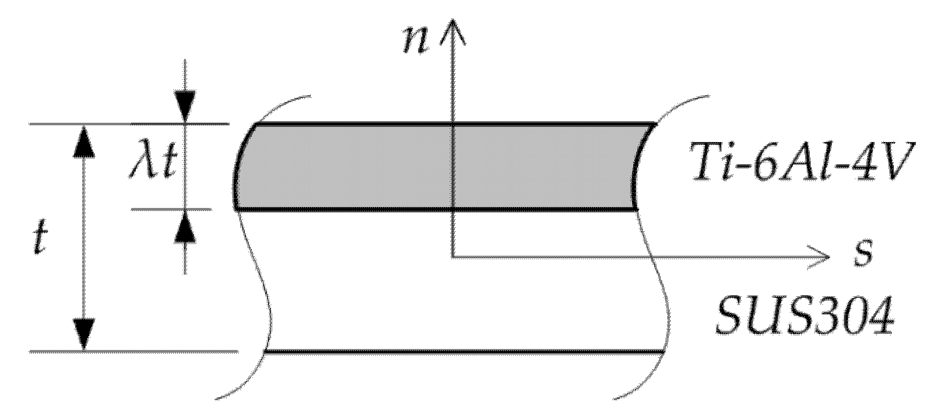
Consider a bimetallic beam made of two different metals. A beam wall with a core thickness of Ti–6Al–4V on the outer surface and SUS304 in the inner part of cross-section beam wall is shown in Figure 1. It is assumed that the layers of materials are perfectly bonded.
If the thermo-elastic material properties are considered as a function of temperature T, they can be calculated for each material, as described in [19,27]:
where P represents Young’s modulus and thermal expansion coefficient , while , ,, and are temperature-dependent coefficients listed in Table 1 for different metals [28]. For simplicity, Poisson’s ratio is assumed to be constant, .
It is assumed that the temperature of the whole beam is uniform and increased from the current ambient temperature to the critical value in incremental steps of 1 °C. If the axial displacements are prevented, the temperature at a point may be raised to , in the way that the beam buckles. is the temperature rise. The temperature that is read as the critical buckling temperature is the temperature difference compared to the ambient temperature. The process can be described as quasi-adiabatic since the heat exchange between the environment and the beam is neglected.
The stress–strain relations of the bimetallic beam can be written as:
where
Using Equations (5), (10) and (11), the beam forces can be expressed in a matrix form as:
where represents the thin-walled beam stiffness, as shown in Appendix A. and are thermal force and thermal moments, respectively:
2.3. Finite Element Formulation
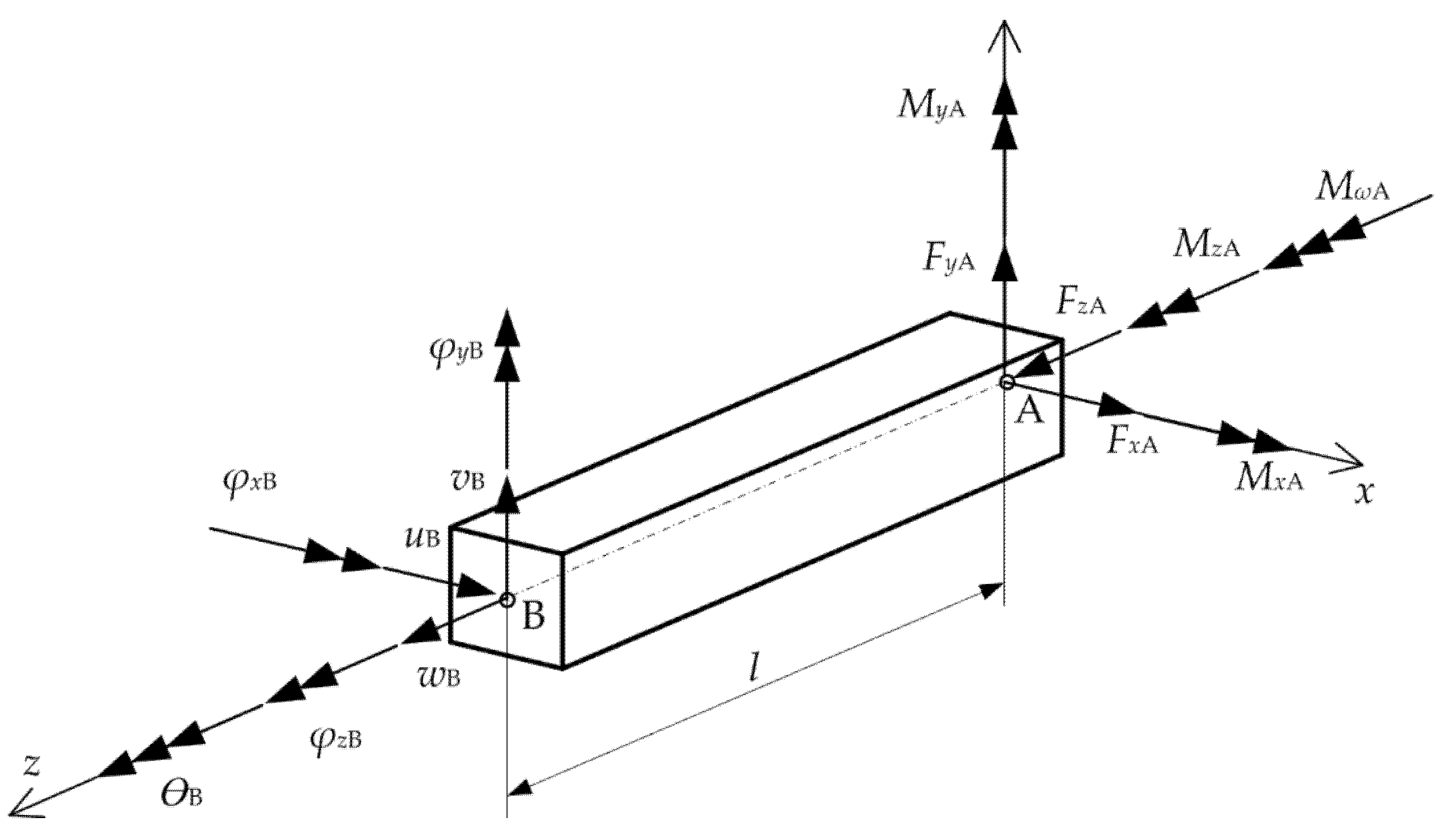
A two-nodded beam element with 14 degrees of freedom is shown in Figure 2. The nodal displacements and nodal force vectors are as follows:
where the superscript e denotes the eth finite element. It should be noted that nodal displacement and nodal forces and are defined in the centroid , while other nodal components are defined in the shear center.
Applying the principle of the virtual work, the incremental equilibrium equations of a beam element in linearized form are:
where the equations from the left side consist of incremental virtual elastic strain energy:
and the incremental virtual geometric potential:
On the right side of the equations, the terms represent the virtual work completed by external forces at the end and at the beginning of the present increment:
In these equations, is the second Piola–Kirchoff stress tensor, denotes the surface tractions, presents the stress–strain tensor and the symbol indicates virtual quantities. By applying the linear interpolation functions for displacement and cubic interpolations for , and , one can obtain:
where is the nodal force vector, is the elastic stiffness matrix and is the geometric stiffness matrix of the beam element. Nonlinear equilibrium equations are solved using the Newton–Raphson method as incremental iterative approach [29,30], and the explicit form of the terms given in nonlinear components were described previously in [31].
3. Results and Discussion
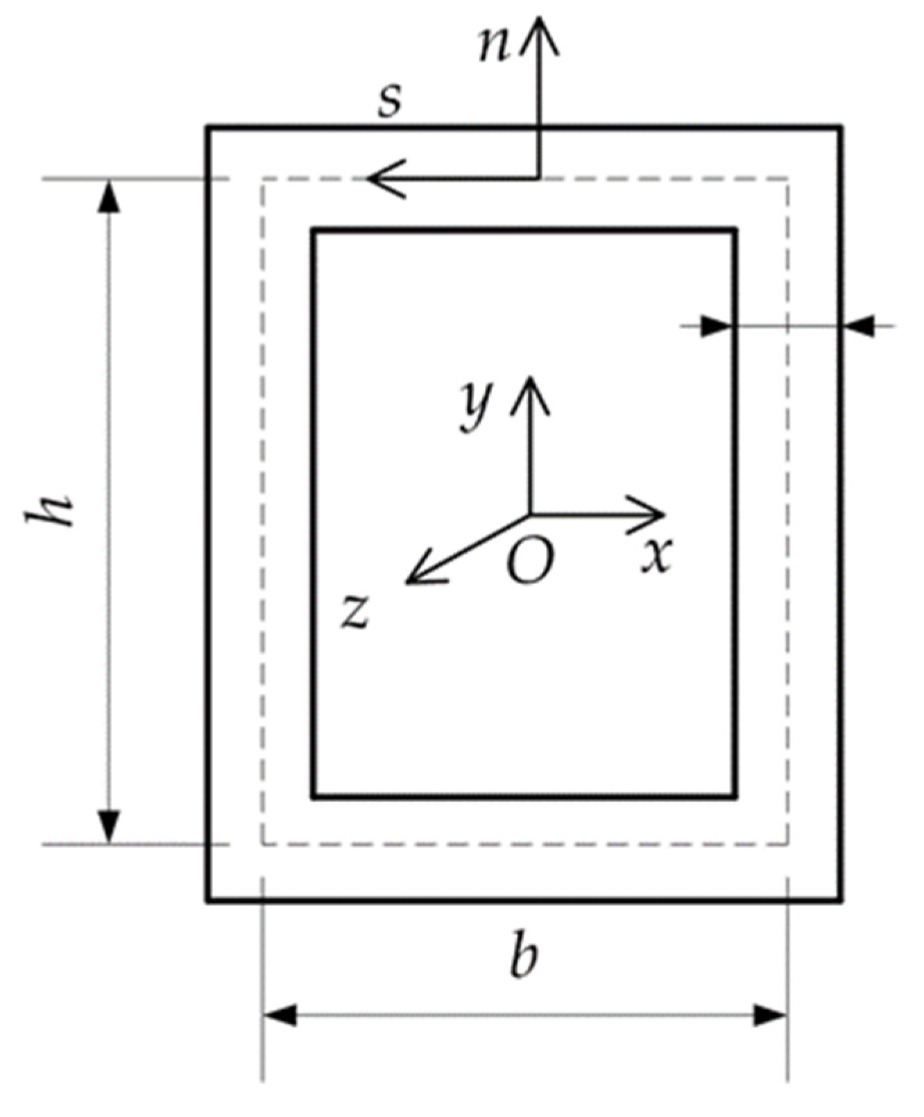
In numerical examples, the thin-walled box beam with height , width and thickness is considered (Figure 3). For verification purposes, the critical buckling temperatures were obtained by shell FEM commercial code [32]. In order to simulate the bimetallic material, the beam walls were divided into two layers of different metals with a variable thickness ratio λ. Note that for , the beam wall is fully SUS304, while as the index thickness ratio λ increases, the beam wall becomes fully Ti-6Al-4V.
3.1. Box Beam
In the first example, the eigenvalue results of the box beam for different boundary conditions, which are clamped–clamped (C-C), clamped–simply supported (C-S) and simply supported (S-S), beam lengths of , and and different material thickness ratios λ are given in Table 2, Table 3 and Table 4. Critical buckling temperatures are given for the first two flexural buckling modes. As the thickness ratio λ increases, the critical buckling temperatures increase as well due to the material properties of TI-6Al-4V. Furthermore, longer beams obtain lower critical buckling temperatures. As expected, clamped–clamped beams exhibit the highest eigenvalues for every beam length. Good agreement of the present results and solutions derived from the 2D model for both flexural buckling modes is achieved.
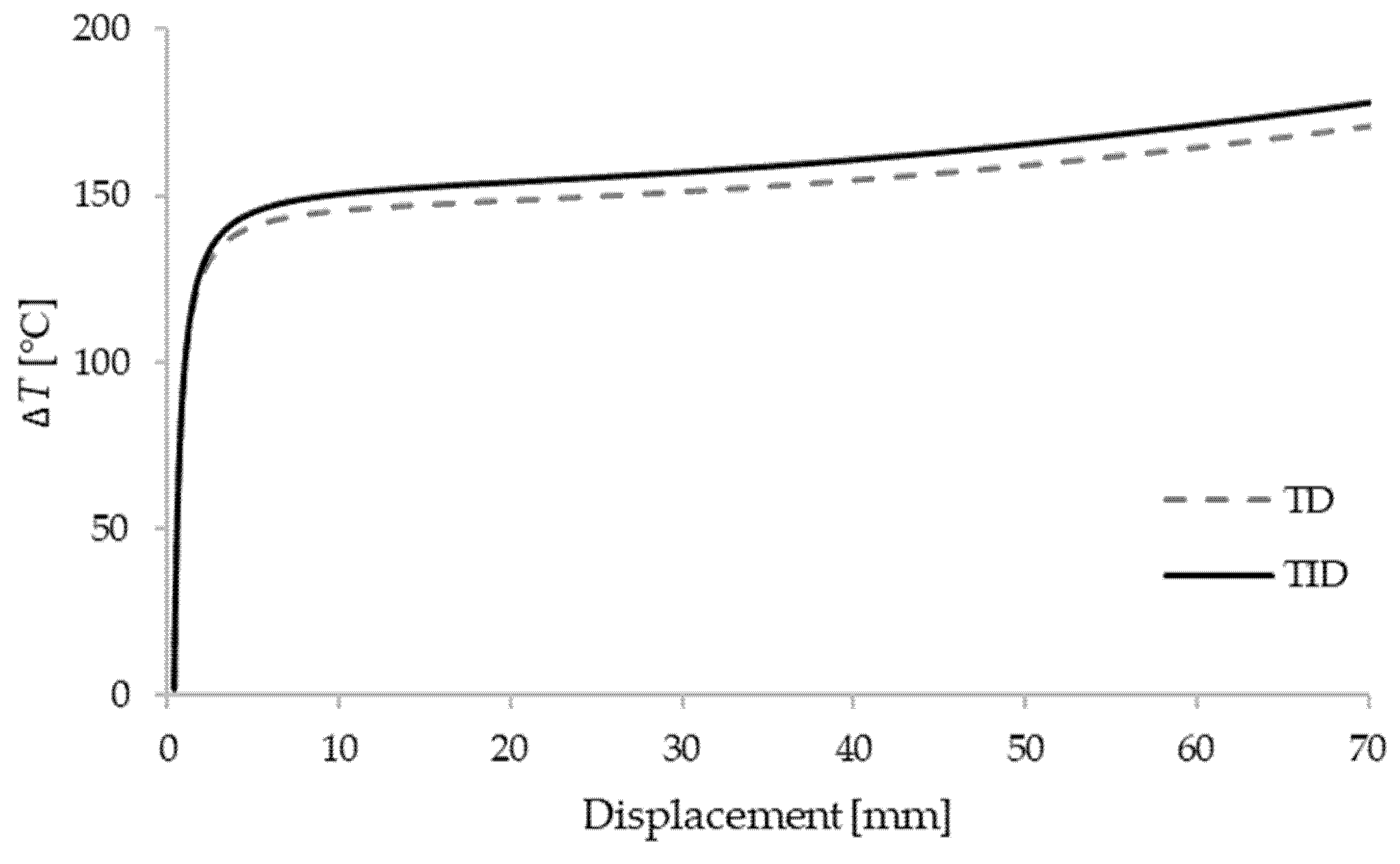
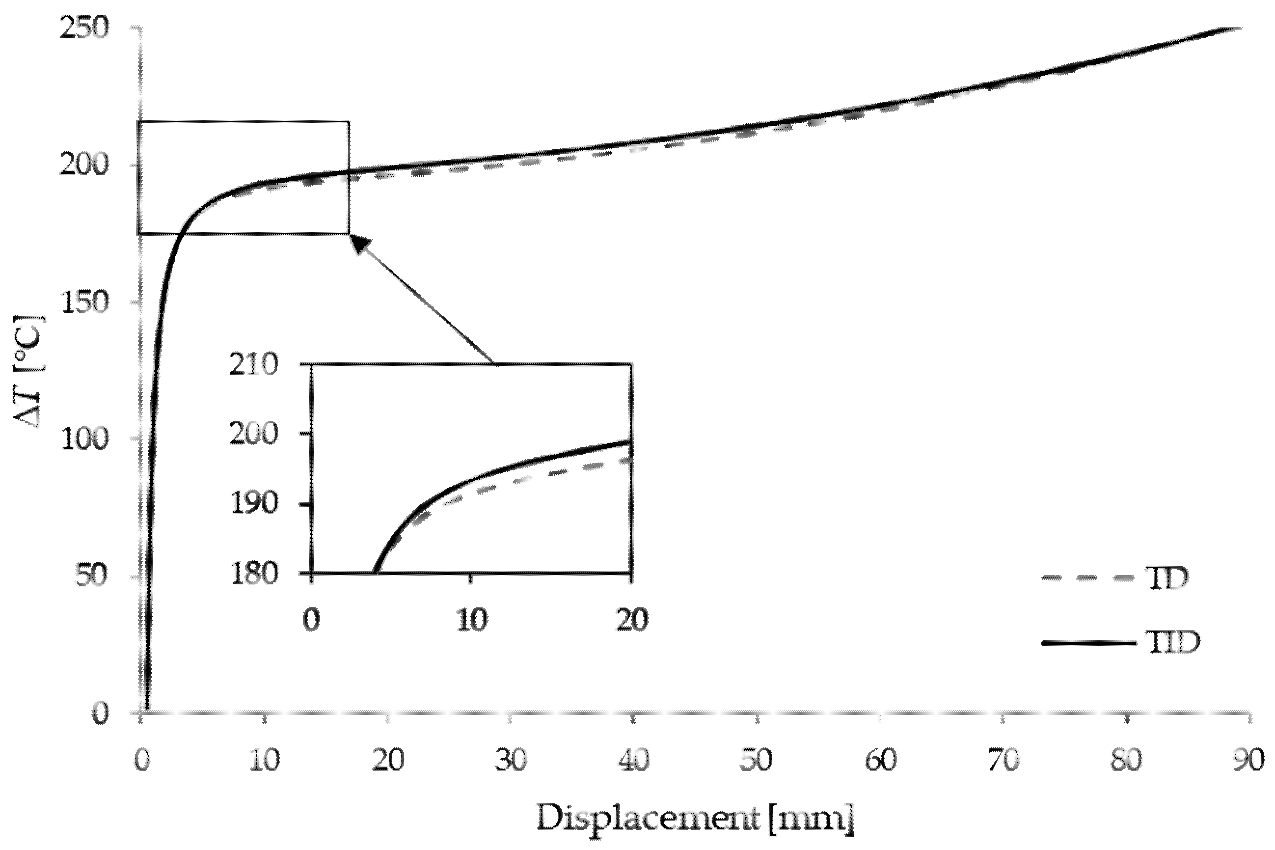
In order to further perform the nonlinear stability analysis of the box beam, a perturbation force of intensity is introduced in the y-axis direction at the midpoint of the clamped–clamped beam. Temperature–displacement curves of the shortest beam with the comparison of temperature-dependent (TD) and temperature-independent (TID) materials are shown in Figure 4, Figure 5 and Figure 6. The results are given for different thickness ratios: , and . It can be seen that curves match very well with the critical buckling temperatures achieved in the eigenvalue manner. As expected, TD solutions obtained lower critical buckling temperatures. In the case of , the difference in critical temperature is around 4%, for the difference is 3.3%, and for it is 1.5%.
3.2. L-Frame
Furthermore, the model is tested for thermal buckling analysis of an L-frame with the length of both legs being and cross-section described in the previous chapter (Figure 7). The frame is fixed at points A and C, while at point B, in-plane translations are prevented.
To verify the results, the critical buckling temperatures for the full SUS304,, and full Ti-6Al-4V , sections are solved by a shell commercial code. To perform nonlinear analysis, a small perturbation force acting in the z-axis direction at point B is applied. The results are shown in Figure 8 for pure metals and for , and . The good recognition of the critical values can be noted. It can be observed that with an increase in the proportion of Ti-6Al-4V material, higher critical temperatures are achieved.
4. Conclusions
A thin-walled beam model capable of thermal buckling analysis has been presented. By means of the updated Lagrangian formulation, the incremental equilibrium equations have been developed using the nonlinear displacement field of the cross-section, taking into account the effects of large rotations. The reliability of the present model was verified by studying the benchmark examples, and the values obtained with the proposed model are in good agreement with those of the shell model. The effects of boundary conditions, the length of the beam and material thickness ratio on the critical buckling temperature and post-buckling response are of great importance. Additionally, it is shown that the TD solutions provide lower values than those of the TID solutions. The model was found to be efficient in predicting eigenvalues and nonlinear buckling behavior.
Author Contributions
Conceptualization, S.K.S. and D.L.; methodology, S.K.S., G.T. and D.L.; software, S.K.S. and D.B.; validation, S.K.S. and D.B.; formal analysis, S.K.S., G.T. and D.L.; investigation, S.K.S.; resources, D.L. and G.T.; data curation, S.K.S.; writing—original draft preparation, S.K.S.; writing—review and editing, S.K.S. and D.L.; visualization, S.K.S.; supervision D.L. and G.T.; project administration, D.L.; funding acquisition, D.L. and G.T. All authors have read and agreed to the published version of the manuscript.
Funding
This research was funded by the Croatian Science Foundation, grant number: IP-2019-04-8615 and University of Rijeka, grant numbers: uniri-tehnic-18-107 and uniri-tehnic-18-139.
Institutional Review Board Statement
Not applicable.
Informed Consent Statement
Not applicable.
Data Availability Statement
Not applicable.
Acknowledgments
The research presented in this paper was made possible by the financial support of Croatian Science Foundation.
Conflicts of Interest
The authors declare no conflict of interest.
Appendix A
References
- Trahair, N.S. Flexural-Torsional Buckling of Structures; CRC Press: Boca Raton, FL, USA, 1993. [Google Scholar]
- Alfutov, N.A. Stability of Elastic Structures; Springer: Berlin/Heidelberg, Germany, 2000. [Google Scholar]
- Bin Kamarudin, M.N.; Mohamed Ali, J.S.; Aabid, A.; Ibrahim, Y.E. Buckling Analysis of a Thin-Walled Structure Using Finite Element Method and Design of Experiments. Aerospace 2022, 9, 541. [Google Scholar] [CrossRef]
- Turkalj, G.; Brnić, J. Nonlinear Stability Analysis of Thin-Walled Frames Using Ul–Esa Formulation. Int. J. Struct. Stab. Dyn. 2004, 4, 45–67. [Google Scholar] [CrossRef]
- Nguyen, N.D.; Vo, T.P.; Nguyen, T.K. An Improved Shear Deformable Theory for Bending and Buckling Response of Thin-Walled FG Sandwich I-Beams Resting on the Elastic Foundation. Compos. Struct. 2020, 254, 112823. [Google Scholar] [CrossRef]
- Pagani, A.; Augello, R.; Carrera, E. Frequency and Mode Change in the Large Deflection and Post-Buckling of Compact and Thin-Walled Beams. J. Sound Vib. 2018, 432, 88–104. [Google Scholar] [CrossRef]
- Lanc, D.; Turkalj, G.; Vo, T.P.; Brnić, J. Nonlinear Buckling Behaviours of Thin-Walled Functionally Graded Open Section Beams. Compos. Struct. 2016, 152, 829–839. [Google Scholar] [CrossRef] [Green Version]
- Lanc, D.; Vo, T.P.; Turkalj, G.; Lee, J. Buckling Analysis of Thin-Walled Functionally Graded Sandwich Box Beams. Thin-Walled Struct. 2015, 86, 148–156. [Google Scholar] [CrossRef] [Green Version]
- Banat, D.; Mania, R.J.; Degenhardt, R. Stress State Failure Analysis of Thin-Walled GLARE Composite Members Subjected to Axial Loading in the Post-Buckling Range. Compos. Struct. 2022, 289, 115468. [Google Scholar] [CrossRef]
- Nguyen, T.-T.; Kim, N.-I.; Lee, J. Analysis of Thin-Walled Open-Section Beams with Functionally Graded Materials. Compos. Struct. 2016, 138, 75–83. [Google Scholar] [CrossRef]
- Nguyen, T.; Lee, J. Optimal Design of Thin-Walled Functionally Graded Beams for Buckling Problems. Compos. Struct. 2017, 179, 459–467. [Google Scholar] [CrossRef]
- Jin, M.X.; Xiang, D.Z. Thermally-Induced Bending-Torsion Coupling Vibration of Large Scale Space Structures. Comput. Mech. 2007, 40, 707–723. [Google Scholar] [CrossRef]
- Saha, S. Thermal Buckling and Postbuckling Characteristics of Extensional Slender Elastic Rods. J. Mech. Eng. 2009, 40, 1–8. [Google Scholar] [CrossRef] [Green Version]
- Cui, D.F.; Hu, H.Y. Thermal Buckling and Natural Vibration of the Beam with an Axial Stick—Slip—Stop Boundary. J. Sound Vib. 2014, 333, 2271–2282. [Google Scholar] [CrossRef]
- George, N.; Jeyaraj, P.; Murigendrappa, S.M. Thin-Walled Structures Buckling of Non-Uniformly Heated Isotropic Beam: Experimental and Theoretical Investigations. Thin Walled Struct. 2016, 108, 245–255. [Google Scholar] [CrossRef]
- Burgreen, D.; Manitt, P.J. Thermal Buckling of a Bimetallic Beams. J. Eng. Mech. Div. 1969, 95, 421–432. [Google Scholar] [CrossRef]
- Burgreen, D.; Regal, D. Higher Mode Buckling of Bimetallic Beam. J. Eng. Mech. Div. 1971, 97, 1045–1056. [Google Scholar] [CrossRef]
- Aydogdu, M. Thermal Buckling Analysis of Cross-Ply Laminated Composite Beams with General Boundary Conditions. Compos. Sci. Technol. 2007, 67, 1096–1104. [Google Scholar] [CrossRef]
- Trinh, L.C.; Vo, T.P.; Thai, H.T.; Nguyen, T.K. An Analytical Method for the Vibration and Buckling of Functionally Graded Beams under Mechanical and Thermal Loads. Compos. Part B Eng. 2016, 100, 152–163. [Google Scholar] [CrossRef]
- Kiani, Y.; Eslami, M.R. Thermal Buckling Analysis of Functionally Graded Material Beams. Int. J. Mech. Mater. Des. 2010, 6, 229–238. [Google Scholar] [CrossRef]
- Kiani, Y.; Eslami, M. Thermomechanical Buckling Dependent FGM Beams Of. Lat. Am. J. Solids Struct. 2013, 10, 223–246. [Google Scholar] [CrossRef]
- Giunta, G.; Crisafulli, D.; Belouettar, S.; Carrera, E. A Thermo-Mechanical Analysis of Functionally Graded Beams via Hierarchical Modelling. Compos. Struct. 2013, 95, 676–690. [Google Scholar] [CrossRef]
- Librescu, L.; Oh, S.Y.; Song, O. Thin-Walled Beams Made of Functionally Graded Materials and Operating in a High Temperature Environment: Vibration and Stability. J. Therm. Stress. 2005, 28, 649–712. [Google Scholar] [CrossRef]
- Ziane, N.; Meftah, S.A.; Ruta, G.; Tounsi, A. Thermal Effects on the Instabilities of Porous FGM Box Beams. Eng. Struct. 2017, 134, 150–158. [Google Scholar] [CrossRef]
- Kvaternik Simonetti, S.; Turkalj, G.; Lanc, D. Thin-Walled Structures Thermal Buckling Analysis of Thin-Walled Closed Section FG Beam-Type Structures. Thin-Walled Struct. 2022, 181, 110075. [Google Scholar] [CrossRef]
- Gjelsvik, A. The Theory of Thin-Walled Bars; Wiley: New York, NY, USA, 1981. [Google Scholar]
- Shen, H.S.; Wang, Z.X. Nonlinear Analysis of Shear Deformable FGM Beams Resting on Elastic Foundations in Thermal Environments. Int. J. Mech. Sci. 2014, 81, 195–206. [Google Scholar] [CrossRef]
- Reddy, J.N.; Chin, C.D. Thermomechanical Analysis of Functionally Graded Cylinders and Plates. J. Therm. Stress. 1998, 21, 593–626. [Google Scholar] [CrossRef]
- Turkalj, G.; Brnic, J.; Kravanja, S. A Beam Model for Large Displacement Analysis of Flexibly Connected Thin-Walled Beam-Type Structures. Thin-Walled Struct. 2011, 49, 1007–1016. [Google Scholar] [CrossRef]
- Bathe, K.J. Finite Element Procedure; Klaus-Jurgen Bathe, 2007. Available online: https://www.amazon.com/Finite-Element-Procedures-K-J-Bathe/dp/097900490X (accessed on 27 September 2022).
- Turkalj, G.; Brnic, J.; Prpic-Orsic, J. Large Rotation Analysis of Elastic Thin-Walled Beam-Type Structures Using ESA Approach. Comput. Struct. 2003, 81, 1851–1864. [Google Scholar] [CrossRef]
- Ansys Mechanical; Release 18.1; Help System. ANSYS, Inc.: Canonsburg, PA, USA. Available online: https://www.ansys.com/academic/terms-and-conditions (accessed on 27 September 2022).
Figure 1.
Bimetallic beam wall.

Figure 2.
Nodal force vectors and displacements.

Figure 3.
Box beam cross-section.

Figure 4.
Critical temperatures vs. displacement for a clamped–clamped beam with .

Figure 5.
Critical temperatures vs. displacement for a clamped–clamped beam with .

Figure 6.
Critical temperatures vs. displacement for a clamped–clamped beam with .

Figure 7.
L-frame.

Figure 8.
Displacements of the L-frame for several values of the material thickness ratio.


Table 1.
Temperature dependent coefficients [19].
Table 1.
Temperature dependent coefficients [19].
| Material | Properties | P0 | P1 | P1 | P2 | P3 |
|---|---|---|---|---|---|---|
| Ti–6Al–4V | E (Pa) | 122.56 × 10⁹ | 0.0 | −4.586 × 10⁻⁴ | 0.0 | 0.0 |
| α (1/K) | 7.5788 × 10⁻⁶ | 0.0 | 6.638 × 10⁻⁴ | –3.147 × 10⁻⁶ | 0.0 | |
| SUS304 | E (Pa) | 201.04 × 10⁹ | 0.0 | 3.079 × 10⁻⁴ | –6.534 × 10⁻⁷ | 0.0 |
| α (1/K) | 12.330 × 10⁻⁶ | 0.0 | 8.086 × 10⁻⁴ | 0.0 | 0.0 |
Table 2.
Critical buckling temperatures of the beam for different boundary conditions and material thickness ratios.
Table 2.
Critical buckling temperatures of the beam for different boundary conditions and material thickness ratios.
| λ | |||||||||
|---|---|---|---|---|---|---|---|---|---|
| BC | Mode | Method | 0 | 0.2 | 0.4 | 0.5 | 0.6 | 0.8 | 1 |
| C-C | Y | Present | 128.87 | 135.26 | 145.83 | 153.64 | 164.09 | 199.19 | 284.51 |
| Shell | 130.22 | 138.77 | 151.18 | 159.72 | 170.71 | 205.83 | 287.97 | ||
| X | Present | 239.24 | 252.56 | 273.89 | 288.9 | 308.62 | 373.43 | 528.16 | |
| Shell | 238.95 | 254.69 | 277.45 | 293.11 | 313.24 | 377.6 | 527.52 | ||
| C-S | Y | Present | 66.58 | 69.91 | 75.39 | 79.44 | 84.84 | 102.97 | 146.98 |
| Shell | 65.98 | 70.313 | 76.604 | 80.936 | 86.504 | 104.29 | 145.66 | ||
| X | Present | 122.87 | 130.02 | 140.09 | 148.58 | 158.73 | 192.03 | 271.48 | |
| Shell | 120.46 | 128.39 | 139.88 | 147.78 | 157.93 | 190.37 | 265.92 | ||
| S-S | Y | Present | 32.72 | 34.368 | 37.07 | 39.06 | 41.72 | 50.62 | 72.24 |
| Shell | 32.196 | 34.314 | 37.39 | 39.507 | 42.226 | 50.904 | 71.077 | ||
| X | Present | 60.28 | 60.29 | 69.07 | 72.86 | 77.83 | 94.15 | 133.08 | |
| Shell | 58.725 | 62.6 | 68.208 | 72.063 | 77.015 | 92.827 | 129.64 | ||
Table 3.
Critical buckling temperatures of the beam for different boundary conditions and material thickness ratios.
Table 3.
Critical buckling temperatures of the beam for different boundary conditions and material thickness ratios.
| λ | |||||||||
|---|---|---|---|---|---|---|---|---|---|
| BC | Mode | Method | 0 | 0.2 | 0.4 | 0.5 | 0.6 | 0.8 | 1 |
| C-C | Y | Present | 73.17 | 76.83 | 82.85 | 87.3 | 93.24 | 113.16 | 161.54 |
| Shell | 73.542 | 78.368 | 85.375 | 90.2 | 96.405 | 116.24 | 162.35 | ||
| X | Present | 135.52 | 142.96 | 154.88 | 163.38 | 174.53 | 211.15 | 298.53 | |
| Shell | 135.02 | 143.91 | 156.78 | 165.62 | 177 | 213.37 | 298.08 | ||
| C-S | Y | Present | 37.63 | 39.52 | 42.63 | 44.91 | 47.97 | 58.21 | 83.07 |
| Shell | 37.323 | 39.774 | 43.33 | 45.783 | 48.933 | 58.997 | 82.396 | ||
| X | Present | 69.35 | 73.33 | 79.45 | 83.81 | 89.53 | 108.31 | 153.09 | |
| Shell | 68.256 | 72.754 | 79.261 | 83.736 | 89.487 | 107.87 | 150.68 | ||
| S-S | Y | Present | 18.45 | 19.38 | 20.9 | 22.03 | 23.53 | 28.55 | 40.73 |
| Shell | 18.211 | 19.409 | 21.149 | 22.346 | 23.885 | 28.793 | 40.204 | ||
| X | Present | 33.95 | 35.9 | 38.9 | 41.04 | 43.84 | 53.03 | 74.95 | |
| Shell | 33.278 | 35.473 | 38.651 | 40.836 | 43.642 | 52.603 | 73.466 | ||
Table 4.
Critical buckling temperatures of the beam for different boundary conditions and material thickness ratios.
Table 4.
Critical buckling temperatures of the beam for different boundary conditions and material thickness ratios.
| λ | |||||||||
|---|---|---|---|---|---|---|---|---|---|
| BC | Mode | Method | 0 | 0.2 | 0.4 | 0.5 | 0.6 | 0.8 | 1 |
| C-C | Y | Present | 47.03 | 49.39 | 53.27 | 56.13 | 59.95 | 72.75 | 103.83 |
| Shell | 47.158 | 50.252 | 54.745 | 57.839 | 61.818 | 74.536 | 104.11 | ||
| X | Present | 86.74 | 91.72 | 99.37 | 104.82 | 111.98 | 135.47 | 191.49 | |
| Shell | 86.605 | 92.308 | 100.56 | 106.23 | 113.53 | 136.86 | 191.19 | ||
| C-S | Y | Present | 24.14 | 25.35 | 27.35 | 28.81 | 30.77 | 37.34 | 53.28 |
| Shell | 23.965 | 25.538 | 27.823 | 29.397 | 31.419 | 37.881 | 52.906 | ||
| X | Present | 44.43 | 46.99 | 50.91 | 53.71 | 57.38 | 69.4 | 98.09 | |
| Shell | 43.872 | 46.763 | 50.945 | 53.822 | 57.518 | 69.335 | 96.854 | ||
| S-S | Y | Present | 11.82 | 12.42 | 13.39 | 14.11 | 15.07 | 18.29 | 26.09 |
| Shell | 11.695 | 12.464 | 13.582 | 14.35 | 15.338 | 18.491 | 25.818 | ||
| X | Present | 21.74 | 22.99 | 24.91 | 26.28 | 28.08 | 33.96 | 47.99 | |
| Shell | 21.396 | 22.807 | 24.85 | 26.255 | 28.059 | 33.82 | 47.234 | ||
Publisher’s Note: MDPI stays neutral with regard to jurisdictional claims in published maps and institutional affiliations. |
© 2022 by the authors. Licensee MDPI, Basel, Switzerland. This article is an open access article distributed under the terms and conditions of the Creative Commons Attribution (CC BY) license (https://creativecommons.org/licenses/by/4.0/).
Share and Cite
MDPI and ACS Style
Simonetti, S.K.; Turkalj, G.; Banić, D.; Lanc, D. Bimetallic Thin-Walled Box Beam Thermal Buckling Response. Materials 2022, 15, 7537. https://0-doi-org.brum.beds.ac.uk/10.3390/ma15217537
AMA Style
Simonetti SK, Turkalj G, Banić D, Lanc D. Bimetallic Thin-Walled Box Beam Thermal Buckling Response. Materials. 2022; 15(21):7537. https://0-doi-org.brum.beds.ac.uk/10.3390/ma15217537
Chicago/Turabian StyleSimonetti, Sandra Kvaternik, Goran Turkalj, Damjan Banić, and Domagoj Lanc. 2022. "Bimetallic Thin-Walled Box Beam Thermal Buckling Response" Materials 15, no. 21: 7537. https://0-doi-org.brum.beds.ac.uk/10.3390/ma15217537
Note that from the first issue of 2016, this journal uses article numbers instead of page numbers. See further details here.