
High-Performance Thermal Interface Materials with Magnetic Aligned Carbon Fibers


Abstract
:
1. Introduction
2. Materials and Methods
2.1. Materials
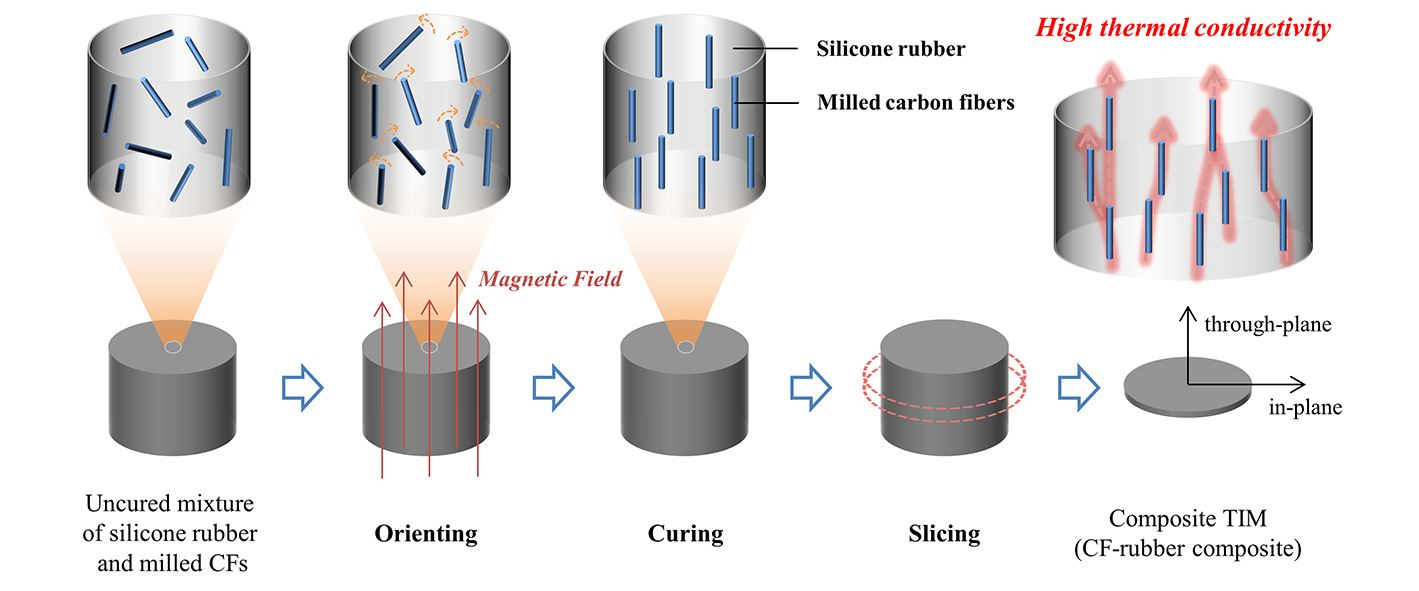
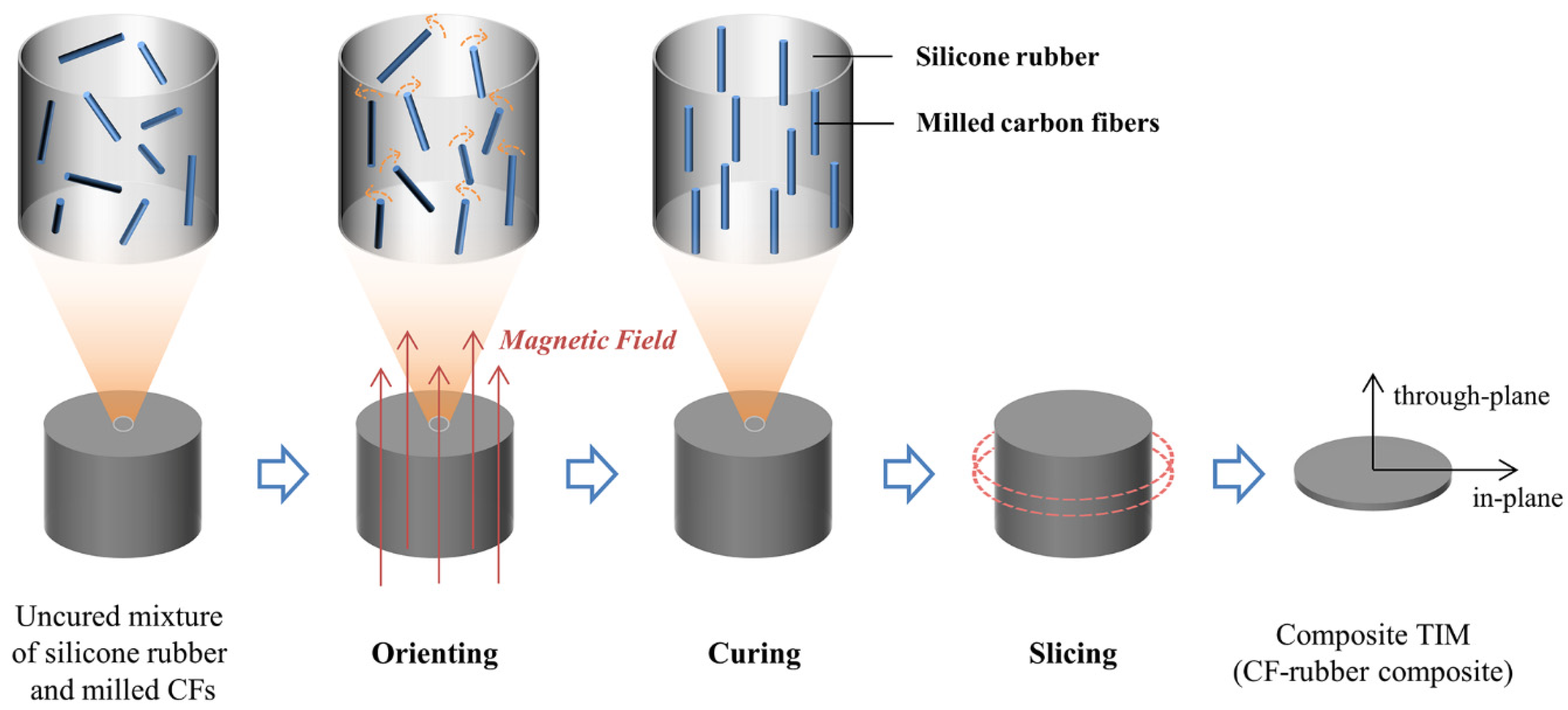
2.2. Preparations
2.3. Characterizations
3. Results and Discussion
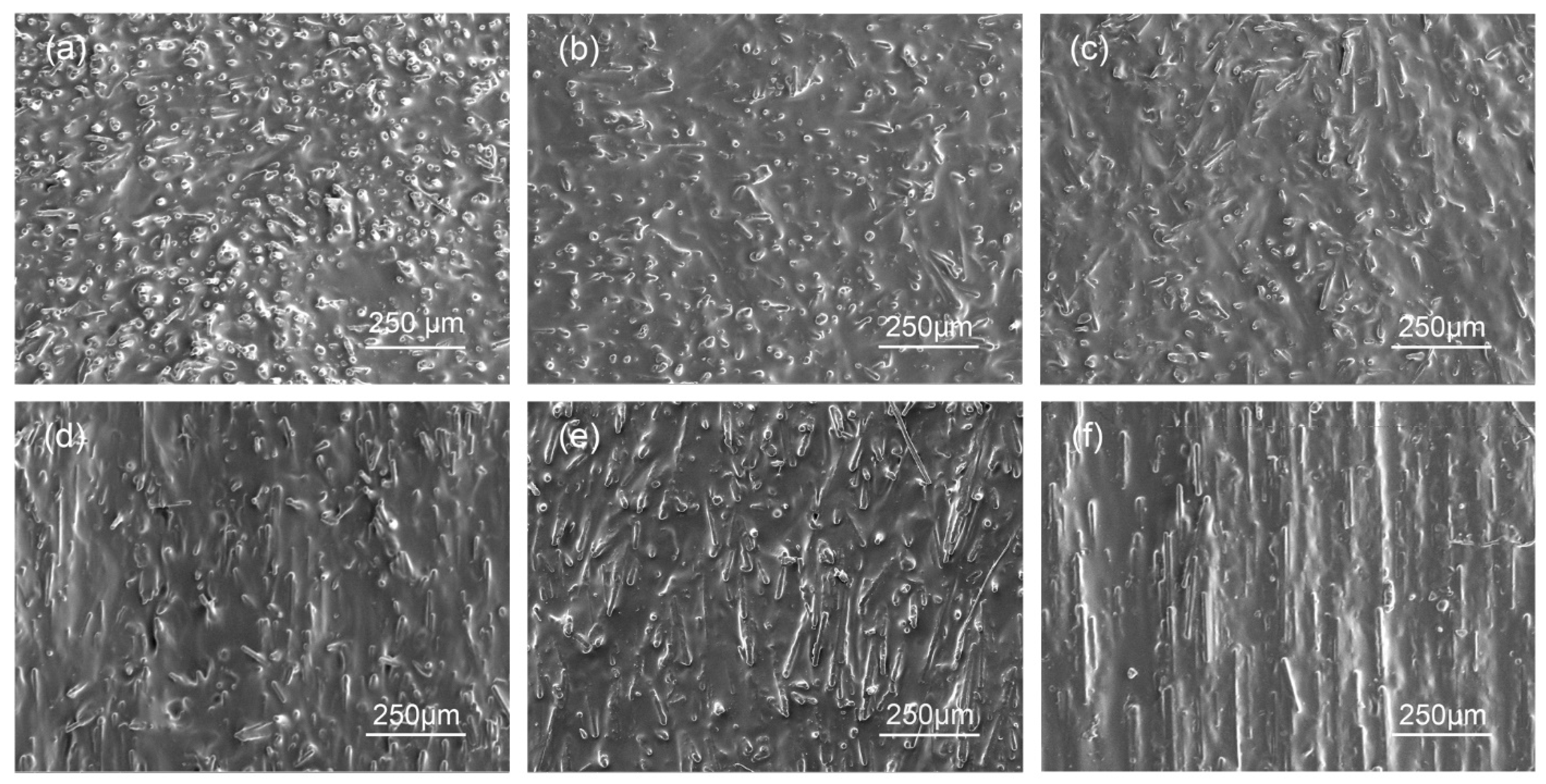
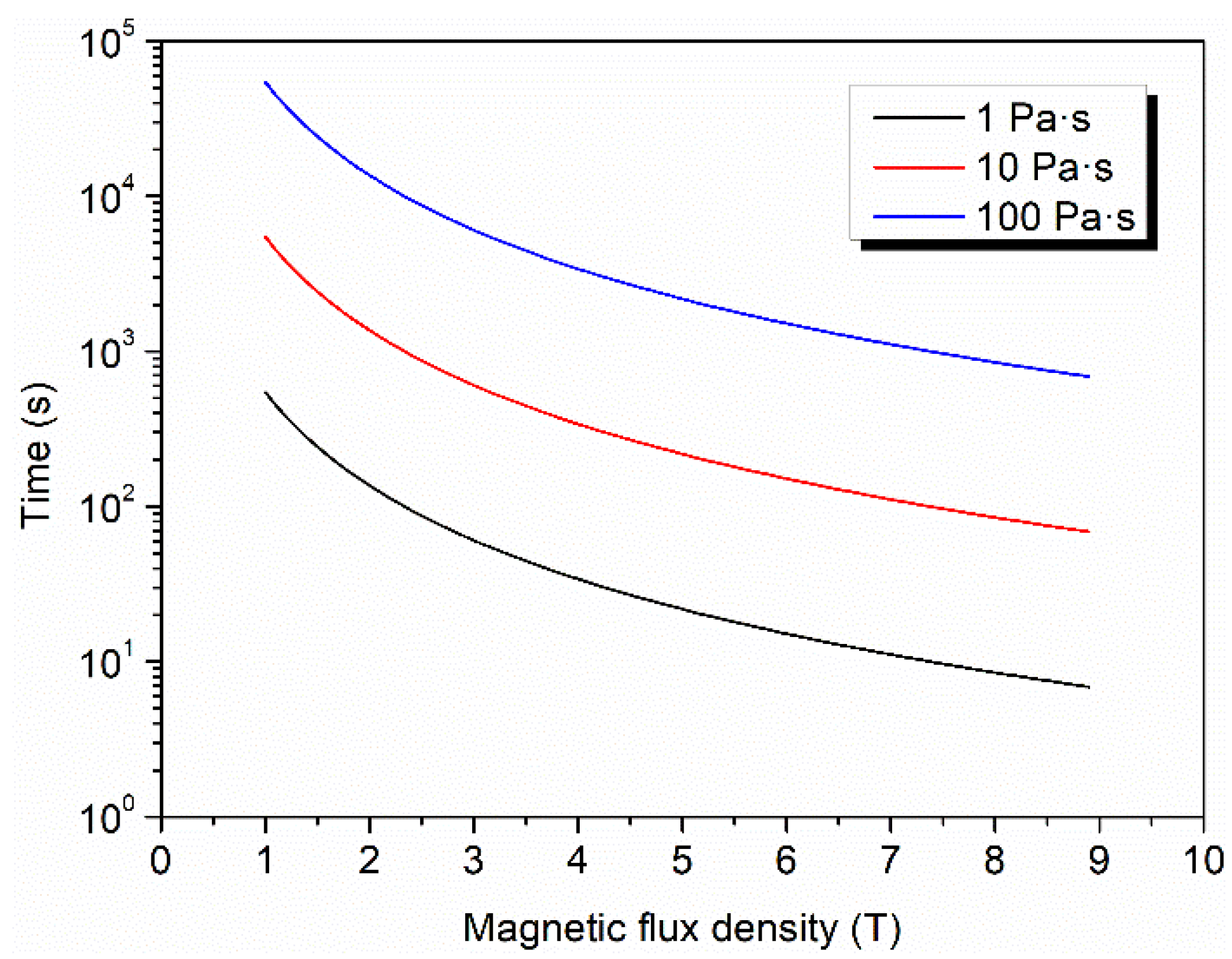
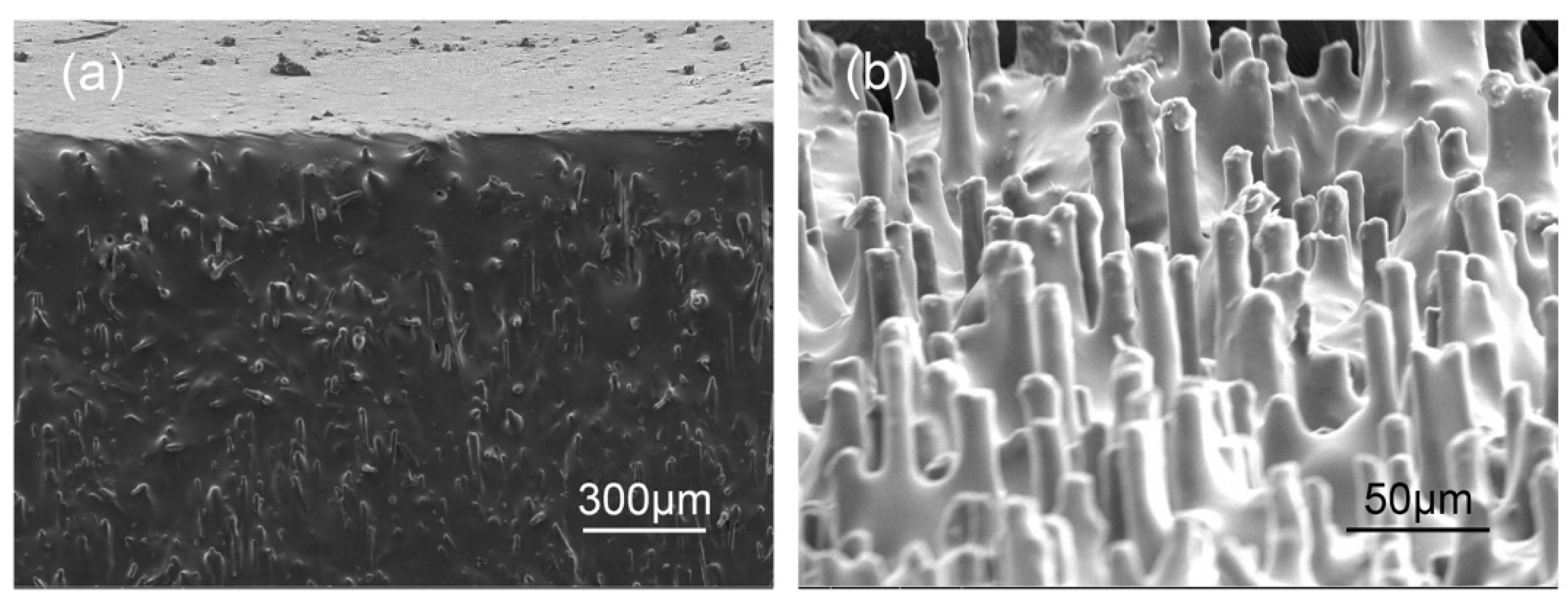
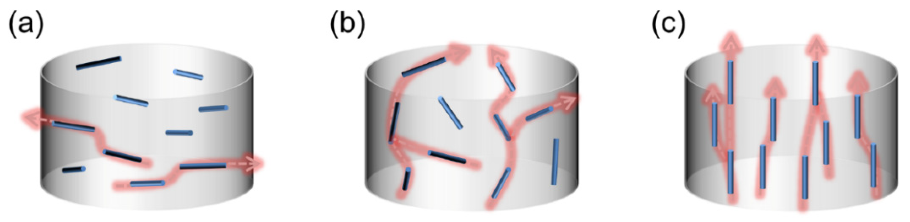
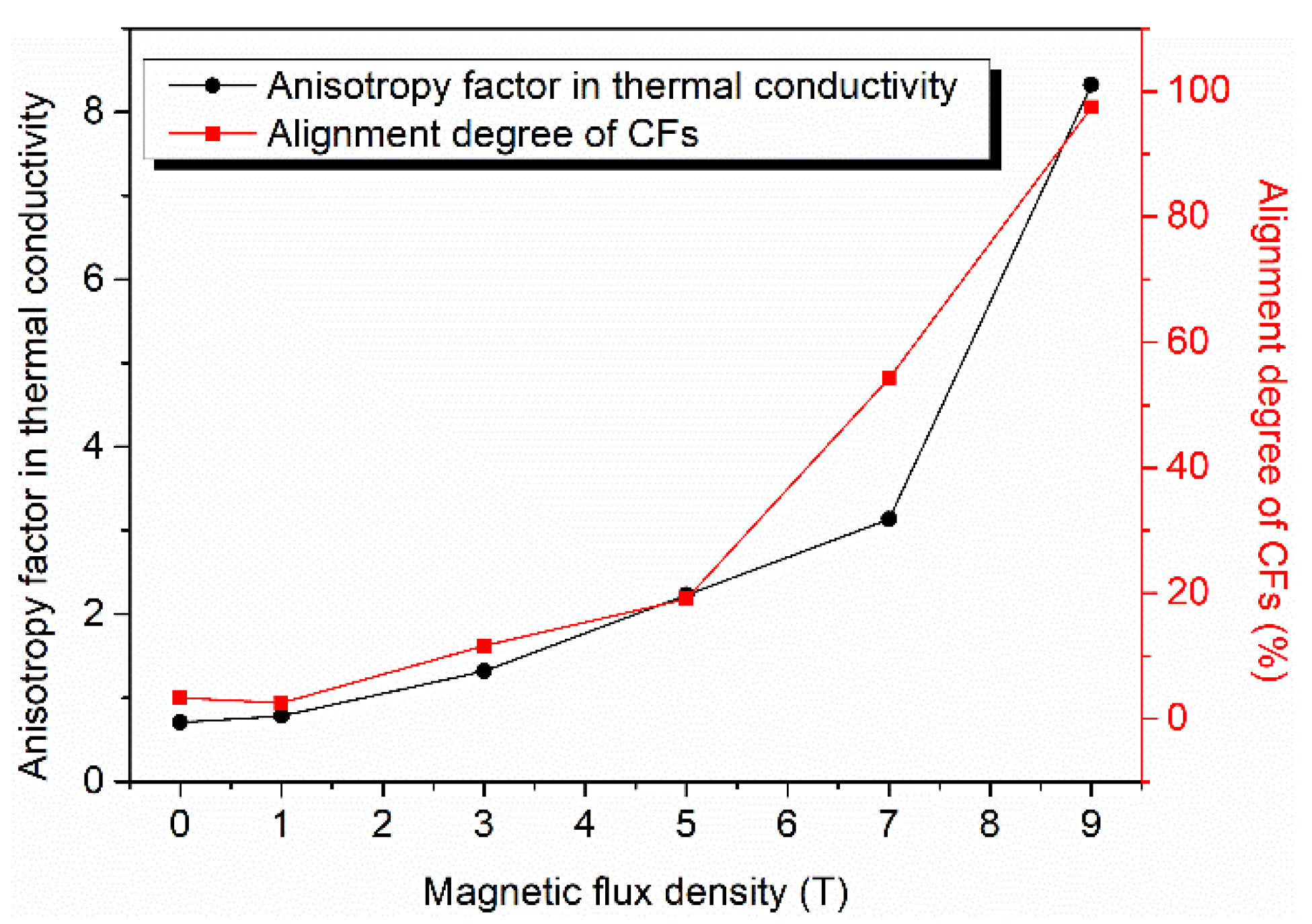
3.1. Alignment of CFs in the CF–Rubber Composites
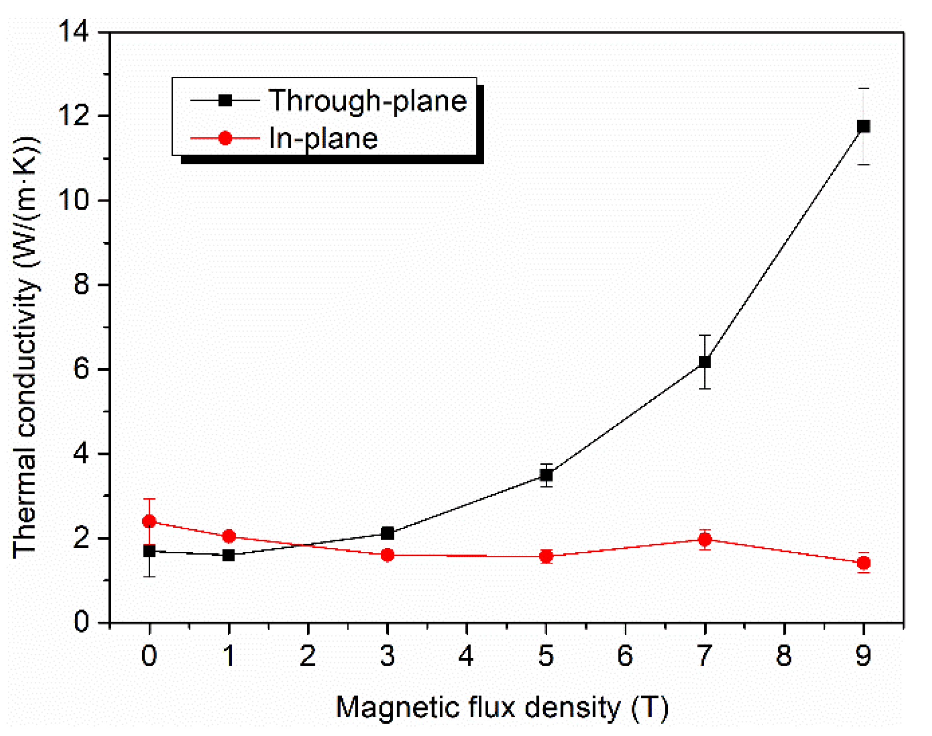
3.2. Thermal and Mechanical Properties of the CF–Rubber Composites
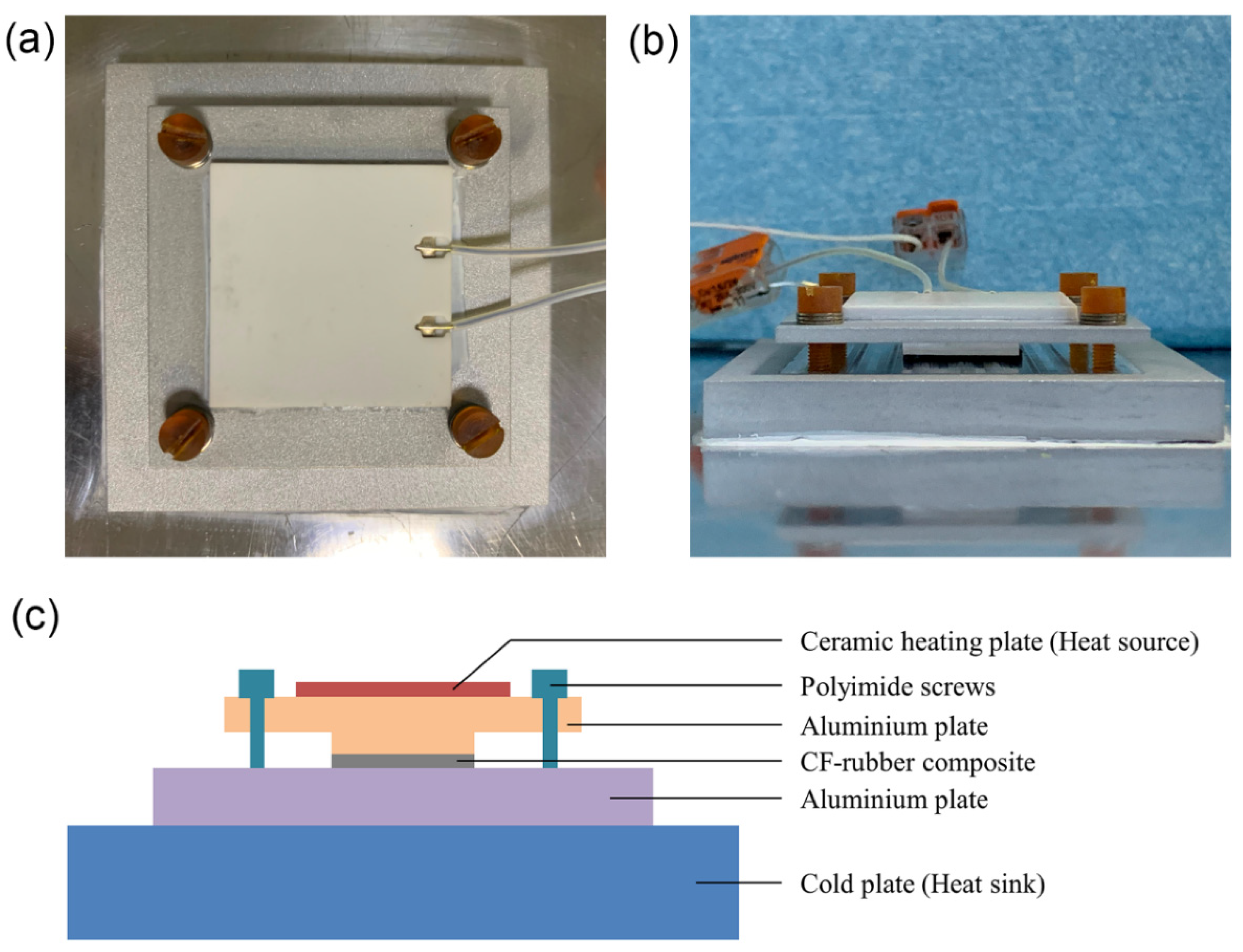
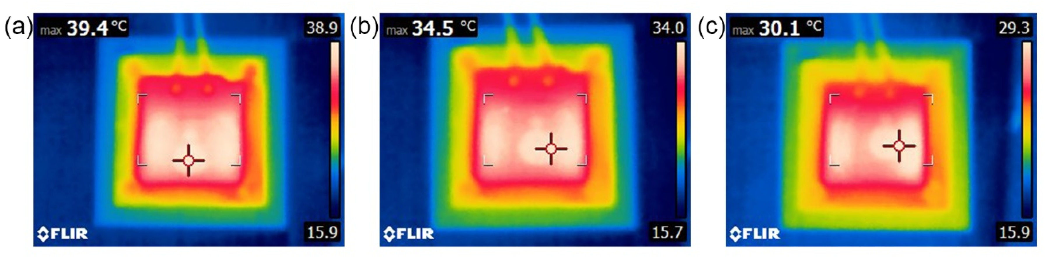
3.3. Thermal Management Performance of the CF–Rubber Composites
4. Conclusions
Supplementary Materials
Author Contributions
Funding
Institutional Review Board Statement
Informed Consent Statement
Data Availability Statement
Conflicts of Interest
References
- Tong, X.C. Advanced Materials for Thermal Management of Electronic Packaging; Springer: New York, NY, USA, 2011; Volume 30. [Google Scholar]
- Chung, D.D.L. Materials for thermal conduction. Appl. Therm. Eng. 2001, 21, 1593–1605. [Google Scholar] [CrossRef]
- Prasher, R. Thermal interface materials: Historical perspective, status, and future directions. Proc. IEEE 2006, 94, 1571–1586. [Google Scholar] [CrossRef]
- Burger, N.; Laachachi, A.; Ferriol, M.; Lutz, M.; Toniazzo, V.; Ruch, D. Review of thermal conductivity in composites: Mechanisms, parameters and theory. Prog. Polym. Sci. 2016, 61, 1–28. [Google Scholar] [CrossRef]
- Uetani, K.; Ata, S.; Tomonoh, S.; Yamada, T.; Yumura, M.; Hata, K. Elastomeric thermal interface materials with high through-plane thermal conductivity from carbon fiber fillers vertically aligned by electrostatic flocking. Adv. Mater. 2014, 26, 5857–5862. [Google Scholar] [CrossRef] [PubMed]
- Chen, H.; Ginzburg, V.V.; Yang, J.; Yang, Y.; Liu, W.; Huang, Y.; Du, L.; Chen, B. Thermal conductivity of polymer-based composites: Fundamentals and applications. Prog. Polym. Sci. 2016, 59, 41–85. [Google Scholar] [CrossRef]
- Erb, R.M.; Libanori, R.; Rothfuchs, N.; Studart, A.R. Composites reinforced in three dimensions by using low magnetic fields. Science 2012, 335, 199–204. [Google Scholar] [CrossRef]
- Pan, G.; Yao, Y.; Zeng, X.; Sun, J.; Hu, J.; Sun, R.; Xu, J.B.; Wong, C.P. Learning from Natural Nacre: Constructing Layered Polymer Composites with High Thermal Conductivity. ACS Appl. Mater. Interfaces 2017, 9, 33001–33010. [Google Scholar] [CrossRef]
- Chen, J.; Huang, X.; Sun, B.; Wang, Y.; Zhu, Y.; Jiang, P. Vertically Aligned and Interconnected Boron Nitride Nanosheets for Advanced Flexible Nanocomposite Thermal Interface Materials. ACS Appl. Mater. Interfaces 2017, 9, 30909–30917. [Google Scholar] [CrossRef] [PubMed]
- Kim, K.; Kim, J. Vertical filler alignment of boron nitride/epoxy composite for thermal conductivity enhancement via external magnetic field. Int. J. Therm. Sci. 2016, 100, 29–36. [Google Scholar] [CrossRef]
- Tanimoto, M.; Yamagata, T.; Miyata, K.; Ando, S. Anisotropic thermal diffusivity of hexagonal boron nitride-filled polyimide films: Effects of filler particle size, aggregation, orientation, and polymer chain rigidity. ACS Appl. Mater. Interfaces 2013, 5, 4374–4382. [Google Scholar] [CrossRef] [PubMed]
- Garmestani, H.; Al-Haik, M.S.; Dahmen, K.; Tannenbaum, R.; Li, D.; Sablin, S.S.; Yousuff Hussaini, M. Polymer-Mediated Alignment of Carbon Nanotubes under High Magnetic Fields. Adv. Mater. 2003, 15, 1918–1921. [Google Scholar] [CrossRef]
- Smith, M.K.; Singh, V.; Kalaitzidou, K.; Cola, B.A. High Thermal and Electrical Conductivity of Template Fabricated P3HT/MWCNT Composite Nanofibers. ACS Appl. Mater. Interfaces 2016, 8, 14788–14794. [Google Scholar] [CrossRef] [PubMed]
- Park, J.G.; Cheng, Q.; Lu, J.; Bao, J.; Li, S.; Tian, Y.; Liang, Z.; Zhang, C.; Wang, B. Thermal conductivity of MWCNT/epoxy composites: The effects of length, alignment and functionalization. Carbon 2012, 50, 2083–2090. [Google Scholar] [CrossRef]
- Liu, M.; Younes, H.; Hong, H.; Peterson, G.P. Polymer nanocomposites with improved mechanical and thermal properties by magnetically aligned carbon nanotubes. Polymer 2019, 166, 81–87. [Google Scholar] [CrossRef]
- Agarwal, S.; Khan, M.M.K.; Gupta1, R.K. Thermal Conductivity of Polymer Nanocomposites Made with Carbon Nanofibers. Polym. Eng. Sci. 2008, 48, 2474–2481. [Google Scholar] [CrossRef]
- Prasse, T.; Cavaillé, J.Y.; Bauhofer, W. Electric anisotropy of carbon nanofibre/epoxy resin composites due to electric field induced alignment. Compos. Sci. Technol. 2003, 63, 1835–1841. [Google Scholar] [CrossRef]
- Wu, S.; Ladani, R.B.; Zhang, J.; Bafekrpour, E.; Ghorbani, K.; Mouritz, A.P.; Kinloch, A.J.; Wang, C.H. Aligning multilayer graphene flakes with an external electric field to improve multifunctional properties of epoxy nanocomposites. Carbon 2015, 94, 607–618. [Google Scholar] [CrossRef] [Green Version]
- Song, W.L.; Cao, M.S.; Lu, M.M.; Yang, J.; Ju, H.F.; Hou, Z.L.; Liu, J.; Yuan, J.; Fan, L.Z. Alignment of graphene sheets in wax composites for electromagnetic interference shielding improvement. Nanotechnology 2013, 24, 115708. [Google Scholar] [CrossRef] [PubMed]
- Yan, H.; Tang, Y.; Long, W.; Li, Y. Enhanced thermal conductivity in polymer composites with aligned graphene nanosheets. J. Mater. Sci. 2014, 49, 5256–5264. [Google Scholar] [CrossRef]
- Lin, F.; Yang, G.; Niu, C.; Wang, Y.; Zhu, Z.; Luo, H.; Dai, C.; Mayerich, D.; Hu, Y.; Hu, J.; et al. Planar Alignment of Graphene Sheets by a Rotating Magnetic Field for Full Exploitation of Graphene as a 2D Material. Adv. Funct. Mater. 2018, 28, 1–7. [Google Scholar] [CrossRef]
- Jung, H.; Yu, S.; Bae, N.S.; Cho, S.M.; Kim, R.H.; Cho, S.H.; Hwang, I.; Jeong, B.; Ryu, J.S.; Hwang, J.; et al. High Through-Plane Thermal Conduction of Graphene Nanoflake Filled Polymer Composites Melt-Processed in an L-Shape Kinked Tube. ACS Appl. Mater. Interfaces 2015, 7, 15256–15262. [Google Scholar] [CrossRef]
- Ghose, S.; Working, D.C.; Connell, J.W.; Smith, J.G.; Watson, K.A.; Delozier, D.M.; Sun, Y.P.; Lin, Y. Thermal conductivity of UltemTM/carbon nanofiller blends. High Perform. Polym. 2006, 18, 961–977. [Google Scholar] [CrossRef]
- Yoo, Y.; Lee, H.L.; Ha, S.M.; Jeon, B.K.; Won, J.C.; Lee, S.G. Effect of graphite and carbon fiber contents on the morphology and properties of thermally conductive composites based on polyamide 6. Polym. Int. 2014, 63, 151–157. [Google Scholar] [CrossRef]
- Zhang, S.; Ke, Y.; Cao, X.; Ma, Y.; Wang, F. Effect of Al2O3 Fibers on the Thermal Conductivity and Mechanical Properties of High Density Polyethylene with the Absence and Presence of Compatibilizer. J. Appl. Polym. Sci. 2012, 124, 4874–4881. [Google Scholar] [CrossRef]
- Choy, C.L.; Leung, W.P.; Kowk, K.W.; Lau, F.P. Elastic moduli and thermal conductivity of injection-molded short-fiber-reinforced thermoplastics. Polym. Compos. 1992, 13, 69–80. [Google Scholar] [CrossRef]
- Feller, J.F.; Roth, S.; Bourmaud, A. Conductive polymer composites: Electrical, thermal, and rheological study of injected isotactic poly(propylene)/long stainless-steel fibers for electromagnetic interferences shielding. J. Appl. Polym. Sci. 2006, 100, 3280–3287. [Google Scholar] [CrossRef]
- Xie, B.H.; Huang, X.; Zhang, G.J. High thermal conductive polyvinyl alcohol composites with hexagonal boron nitride microplatelets as fillers. Compos. Sci. Technol. 2013, 85, 98–103. [Google Scholar] [CrossRef]
- Lin, G.; Xie, B.H.; Hu, J.; Huang, X.; Zhang, G.J. Aligned graphene oxide nanofillers: An approach to prepare highly thermally conductive and electrically insulative transparent polymer composites. J. Nanomater. 2015, 2015, 957068. [Google Scholar] [CrossRef] [Green Version]
- Zhou, S.X.; Zhu, Y.; Du, H.D.; Li, B.H.; Kang, F.Y. Preparation of oriented graphite/polymer composite sheets with high thermal conductivities by tape casting. New Carbon Mater. 2012, 27, 241–249. [Google Scholar] [CrossRef]
- Datsyuk, V.; Trotsenko, S.; Reich, S. Carbon-nanotube-polymer nanofibers with high thermal conductivity. Carbon 2013, 52, 605–608. [Google Scholar] [CrossRef] [Green Version]
- Terao, T.; Zhi, C.; Bando, Y.; Mitome, M.; Tang, C.; Golberg, D. Alignment of boron nitride nanotubes in polymeric composite films for thermal conductivity improvement. J. Phys. Chem. C 2010, 114, 4340–4344. [Google Scholar] [CrossRef]
- Yousefi, N.; Gudarzi, M.M.; Zheng, Q.; Aboutalebi, S.H.; Sharif, F.; Kim, J.K. Self-alignment and high electrical conductivity of ultralarge graphene oxide-polyurethane nanocomposites. J. Mater. Chem. 2012, 22, 12709–12717. [Google Scholar] [CrossRef]
- Zeng, H.; Wu, J.; Ma, Y.; Ye, Y.; Liu, J.; Li, X.; Wang, Y.; Liao, Y.; Luo, X.; Xie, X.; et al. Scalable Approach to Construct Self-Assembled Graphene-Based Films with An Ordered Structure for Thermal Management. ACS Appl. Mater. Interfaces 2018, 10, 41690–41698. [Google Scholar] [CrossRef] [PubMed]
- Vincent, M.; Giroud, T.; Clarke, A.; Eberhardt, C. Description and modeling of fiber orientation in injection molding of fiber reinforced thermoplastics. Polymer 2005, 46, 6719–6725. [Google Scholar] [CrossRef]
- Yang, C.; Huang, H.-X.; Li, K. Investigation of Fiber Orientation States in Injection-Compression Molded Short-Fiber-Reinforced Thermoplastics. Polym. Compos. 2010, 31, 1899–1908. [Google Scholar] [CrossRef]
- Chung, J.Y.; Lee, J.G.; Baek, Y.K.; Shin, P.W.; Kim, Y.K. Magnetic field-induced enhancement of thermal conductivities in polymer composites by linear clustering of spherical particles. Compos. Part B Eng. 2018, 136, 215–221. [Google Scholar] [CrossRef]
- Kim, K.; Kim, J. Magnetic aligned AlN/epoxy composite for thermal conductivity enhancement at low filler content. Compos. Part B Eng. 2016, 93, 67–74. [Google Scholar] [CrossRef]
- Lin, Z.; Liu, Y.; Raghavan, S.; Moon, K.S.; Sitaraman, S.K.; Wong, C.P. Magnetic alignment of hexagonal boron nitride platelets in polymer matrix: Toward high performance anisotropic polymer composites for electronic encapsulation. ACS Appl. Mater. Interfaces 2013, 5, 7633–7640. [Google Scholar] [CrossRef]
- Yuan, C.; Duan, B.; Li, L.; Xie, B.; Huang, M.; Luo, X. Thermal Conductivity of Polymer-Based Composites with Magnetic Aligned Hexagonal Boron Nitride Platelets. ACS Appl. Mater. Interfaces 2015, 7, 13000–13006. [Google Scholar] [CrossRef]
- Chung, S.H.; Kim, H.; Jeong, S.W. Improved thermal conductivity of carbon-based thermal interface materials by high-magnetic-field alignment. Carbon 2018, 140, 24–29. [Google Scholar] [CrossRef]
- Kimura, T.; Yamato, M.; Koshimizu, W.; Koike, M.; Kawai, T. Magnetic orientation of polymer fibers in suspension. Langmuir 2000, 16, 858–861. [Google Scholar] [CrossRef]


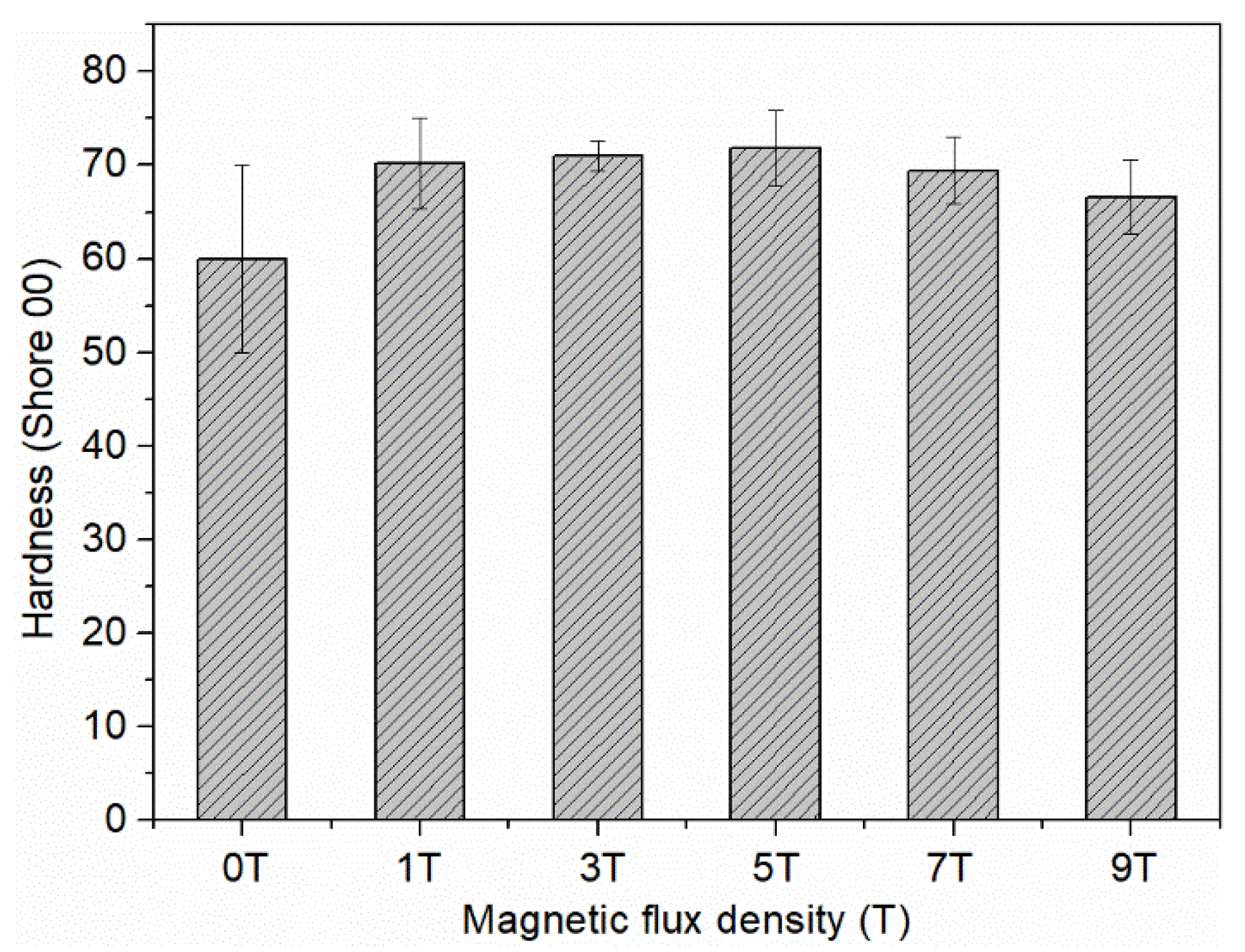
| Magnetic Flux Density (T) | 0 | 1 | 3 | 5 | 7 | 9 |
| δ (%) | 3.34 | 2.53 | 11.64 | 19.10 | 54.21 | 97.38 |
Publisher’s Note: MDPI stays neutral with regard to jurisdictional claims in published maps and institutional affiliations. |
© 2022 by the authors. Licensee MDPI, Basel, Switzerland. This article is an open access article distributed under the terms and conditions of the Creative Commons Attribution (CC BY) license (https://creativecommons.org/licenses/by/4.0/).
Share and Cite
Wu, Q.; Miao, J.; Li, W.; Yang, Q.; Huang, Y.; Fu, Z.; Yang, L. High-Performance Thermal Interface Materials with Magnetic Aligned Carbon Fibers. Materials 2022, 15, 735. https://0-doi-org.brum.beds.ac.uk/10.3390/ma15030735
Wu Q, Miao J, Li W, Yang Q, Huang Y, Fu Z, Yang L. High-Performance Thermal Interface Materials with Magnetic Aligned Carbon Fibers. Materials. 2022; 15(3):735. https://0-doi-org.brum.beds.ac.uk/10.3390/ma15030735
Chicago/Turabian StyleWu, Qi, Jianyin Miao, Wenjun Li, Qi Yang, Yanpei Huang, Zhendong Fu, and Le Yang. 2022. "High-Performance Thermal Interface Materials with Magnetic Aligned Carbon Fibers" Materials 15, no. 3: 735. https://0-doi-org.brum.beds.ac.uk/10.3390/ma15030735