
Machinability of Different Wood-Plastic Composites during Peripheral Milling

1
Co-Innovation Center of Efficient Processing and Utilization of Forest Resources, Nanjing Forestry University, Nanjing 210037, China
2
College of Furnishings and Industrial Design, Nanjing Forestry University, Nanjing 210037, China
3
Wood Science and Engineering, Luleå University of Technology, 931 87 Skellefteå, Sweden
4
College of Materials Science and Technology, Nanjing Forestry University, Nanjing 210037, China
*
Author to whom correspondence should be addressed.
Materials 2022, 15(4), 1303; https://0-doi-org.brum.beds.ac.uk/10.3390/ma15041303
Submission received: 7 January 2022
/
Revised: 30 January 2022
/
Accepted: 8 February 2022
/
Published: 10 February 2022
(This article belongs to the Special Issue Manufacturing and Mechanics of Materials)
Abstract
:The aim of this study was to improve the machinability of wood-plastic composites by exploring the effects of different wood-plastic composites on machinability. In particular, the effects of milling with cemented carbide cutters were assessed by investigating cutting forces, cutting temperature, surface quality, chip formation, and tool wear. The cutting parameters determined to yield an optimal surface quality were rake angle 2°, cutting speed 9.0 m/s, feed per tooth 0.3 mm, and cutting depth 1.5 mm. In these optimized milling conditions, the wood-plastic composite with polypropylene exhibited the highest cutting forces, cutting temperature, and tool wear, followed by polyethylene and polyvinyl chloride wood-plastic composites. Two wear patterns were determined during wood-plastic composite machining, namely chipping and flaking. Due to the different material composition, semi-discontinuous ribbon chips and continuous ribbon chips were generated from the machining process of wood-plastic composites with polypropylene and polyethylene, respectively. The wood-plastic composite with polyvinyl chloride, on the other hand, formed needle-like chips. These results contribute to a theoretical and practical basis for improved wood-plastic composite machining in industrial settings.
1. Introduction
Wood-plastic composites (WPC) made by mixing wood fiber or wood dust with plastic followed by extrusion and hot-pressing are an environmentally friendly alternative to traditional building materials [1,2]. With excellent inherent fire resistance and processability making them compatible with a variety of industrial molding and infrastructure, WPCs find applications in interior and exterior markets pertaining to furnishing, decorating, and packing, to name a few [3,4]. WPCs can be of different types depending on their plastic component, such as polypropylene (WPPC), polyethylene (WPEC), or polyvinyl chloride (WPVCC) [5,6,7]. Unlike plastics, for which production is primarily through extrusion, WPC products are manufactured using drilling, planing, turning, and milling [8,9]. This leads to issues pertaining to cutting forces and temperature, surface quality, chip formation, and tool wear, much like the case of traditional timber. Understanding the effects machining processes have on WPC products is critical, not only to create better quality products, but also to enhance tool longevity. Thus, it is not surprising that many researchers focus on understanding these aspects of WPC machining.
In the recent past, effects of cutting forces, heat, machined surface quality, chip formation, and tool wear on the machinability of WPC were assessed [10]. It is important to note that tool geometries and certain cutting parameters also influence these effects. For instance, Guo et al. [11] explored the changes in cutting forces and surface roughness during orthogonal machining of WPC and found that they were positively related to cutting depth. Their results also confirmed that when the cutting depth was low, the process resulted in curly and continuous chips. In a subsequent study, it was determined that chips resulting from orthogonal cutting of WPC could exhibit four distinct morphologies: short continuous, long continuous, granule, and flake. Shi et al. [12] investigated variations in chip size during WPC milling and found that while thickness was positively correlated with feed speed, the opposite was true for cutting speed. Through a systematic study which considered multiple process factors, Pei et al. [13] confirmed that cutting depth contributed most to cutting temperature, followed by spindle speed and cutting width. Interestingly, they also found that most of the heat generated during cutting was taken away by the chips generated. In yet another study investigating surface quality of WPC subjected to turning, Hutyriva et al. showed that cutting quality increased when high spindle speeds and slow feed rates were used [14]. In a related study, a series of carefully designed drilling experiments revealed that surface defects on WPC are strongly linked to tool geometries and material properties [15].
When it comes to industrial machining, cutting WPC is challenging owing to the diverse types of plastics they contain. Irrespective of the type of WPC, plastics inherently have low thermal stability and are easily affected by the heat generated during cutting processes. This thermal-mechanical coupling leads to knockdown effects on the overall precision of the machining process and final surface quality of WPC products [16]. To make things worse, WPCs are two to four times denser than traditional wood-based materials, which increases the wear rate of the cutting tool considerably [17]. Considering WPC is a relatively new material, extensive research exploring key machining parameters to optimize its machinability and improve manufacturing yield is the need of the hour.
Thus, this study’s objective was to identify possible relations between cutting forces, cutting temperature, surface roughness, chip formation, and tool wear pertaining to WPC machining with cemented carbide cutters. Specifically, optimized cutting parameters for three types of WPC, namely, WPPC, WPEC, and WPVCC, were determined by assessing surface finish quality and tool wear, amongst others. These findings can provide scientific guidance to improve WPC machining practices in the industry.
2. Materials and Methods
2.1. Workpiece and Cutting Tool
Table 1 lists the three types of WPCs, namely, WPPC, WPEC, and WPVCC (Guofeng Wood-Plastic Composite Company Co., Ltd., Anhui, China) used in this study. All three types of WPC were obtained from 4:5 mixtures of the plastic and wood fiber and were processed by extrusion, molding, and injection molding. Details of the material composition and properties of all WPCs prepared for this work are provided in Table 1. Cutters used to machine WPC were supplied by Leitz Tooling System Co. Ltd. (Nanjing, China). The inserts fixed on the cutter’s body comprised tungsten carbide, cobalt, and other compounds. Table 2 presents the tool geometries and tool material properties.
2.2. Experimental Set-Up
Up milling was performed on a computerized numerical control machine (MGK01, Nanxing Machinery Co., Ltd., Dongguan, China) in dry conditions. As shown in Figure 1a, dynamic cutting force signals were monitored using a three-dimensional piezoelectric dynamometer (Kistler 9257B, Switzerland) with a charge amplifier (5070A, Switzerland) connected to a computer. In this work, straight tooth cutting tools were used, and only the tangential forces (Ft) and normal forces (Fn) were studied. These forces were calculated based on Equations (1) and (2):
where θ denotes the angle between the feeding and rotation directions in °; ap is the cutting depth in mm; D represents the tool diameter of 18 cm; Ft and Fn are defined as the force components perpendicular and parallel to the radius direction in N, respectively (see Figure 1a inset); and Fx and Fy are the measured forces parallel and perpendicular to the feeding direction in N, respectively (see Figure 1a inset).
An infrared imaging camera with an emissivity of 0.9 (Figure 1b, A20-M, Thermo Fisher Co. Ltd., Waltham, MA, USA) was used to measure and monitor the dynamic cutting temperature during milling. The dynamic temperature of the cutting-edge of the tool and the chips are represented by the characters T1 and T2, respectively (Figure 1b inset), while the room temperature was 24 °C. Furthermore, surface roughness Ra was used to evaluate the smooth machined surface, and was measured using a surface profilometer with sensitivity of 0.1–20 nm (S-NEX001SD-12, Olympus, Co. Ltd., Tokyo, Japan). Finally, morphologies of chips and the extent of tool wear were observed using a scanning electron microscope (Quanta 200, FEI Group Co. Ltd., Hillsboro, OR, USA). Finally, radius of the tool edge was measured with an optical microscope (SZX16, Olympus Co. Ltd., Tokyo, Japan).
2.3. Experimental Design
In this work, two groups of milling experiments, designated as Experiments I and II, were designed. Experiment I was used to determine a set of optimal cutting parameters which result in the lowest surface roughness values for cut specimens. Experiment II was designed to investigate the effect of different kinds of plastic contained in WPC on the machinability of WPC, using the optimal cutting parameters obtained from Experiment I.
In Experiment I, the selection of experimental cutting factors shown in Table 3 was based on industrial WPC machining best practices and the Taguchi method [18]. An L27 (43) orthogonal array was adopted, with three different levels of rake angle α (°), cutting speed v (m/s), feed per tooth Uz (mm/Z), and cutting depth ap (mm). Calculated signal-to-noise ratio (SNR) values were used to determine a group of optimal cutting parameters derived from the experimental cutting factors. These optimal cutting parameters are expected to yield the lowest surface roughness Ra, i.e., the lowest value of SNR will correspond to the highest cutting quality. The equation to obtain SNR values is Equation (3) [19]:
where n is the testing number and yi is the Ra value of each testing.
In Experiment II, the machinability of WPPC, WPEC, and WPVCC using the optimal cutting parameters was investigated. The machinability parameters monitored included cutting forces, cutting temperature, chip formation, and tool wear.
3. Results and Discussion
3.1. Optimal Cutting Parameters for Wood-Plastic Composite Machining
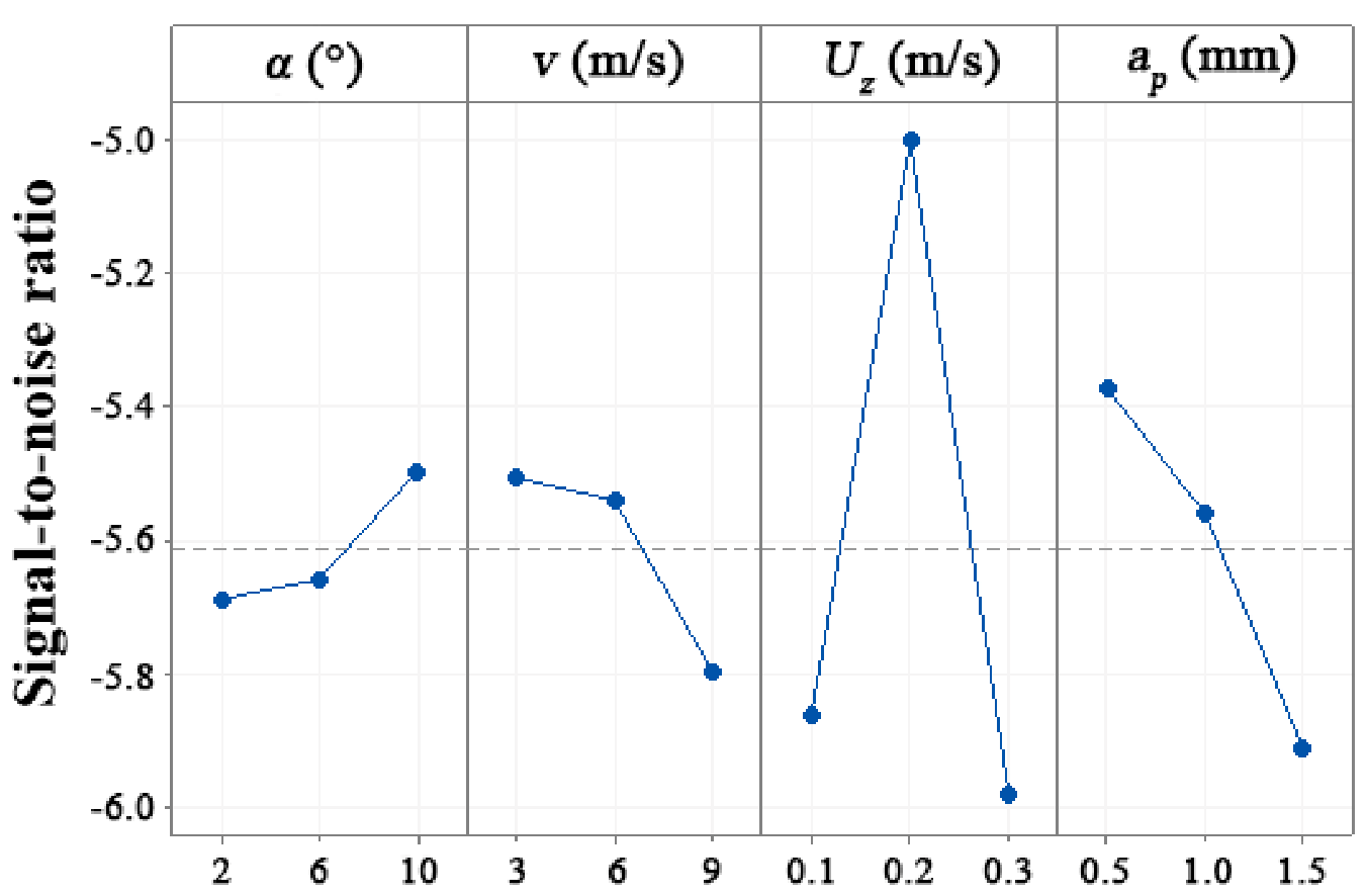
Results of SNR values calculated using Equation (3) are provided in Table 4. A higher delta value means a more pronounced contribution of the experimental cutting factor to the surface roughness. Bearing this in mind, feed per tooth gave a delta value of 0.982 (Rank 1), followed by cutting depth (delta = 0.539, Rank 2), cutting speed (delta = 0.292, Rank 3), and rake angle (delta = 0.192, Rank 4). Thus, feed per tooth exhibits the strongest influence on surface roughness, followed by cutting depth, cutting speed, and rake angle, in that order.
The effects of all these experimental cutting factors on SNR values pertaining to surface roughness are shown in Figure 2. Based on the determined SNR values for Ra and their respective ranks, the optimal combination of cutting parameters was determined to correspond with the lowest value of SNR for each experimental cutting factor. The optimal cutting parameters determined in this study were rake angle 2°, cutting speed 9.0 m/s, feed per tooth 0.3 mm, and cutting depth 1.5 mm. This is in contrast to traditional wood materials [20,21,22,23]. Optimal cutting parameters for WPC yielding the lowest surface roughness were determined to include a higher rake angle and cutting speed, at a lower feed per tooth and cutting depth. This phenomenon is thought to be caused by the plastic contained in WPCs. With a decrease in rake angle and an increase in cutting speed, feed per tooth, and cutting depth, higher friction may be generated between the WPCs and cutters, which leads to a higher cutting temperature. The heat makes the WPC less rigid, resulting in the edges of the WPC, which are more susceptible to penetration, being shorn off.
3.2. Effects of Wood-Plastic Composite Types on Cutting Forces
Figure 3 shows the tangential and normal dynamic cutting forces (Ft and Fn) for WPPC, WPEC, and WPVCC at the optimal combination of cutting parameters (α = 2°, v = 9.0 m/s, Uz = 0.3 mm, and ap = 1.5 mm). The data indicate that the tangential force was consistently higher than the normal force, irrespective of the type of WPC. Furthermore, WPPC had the highest cutting forces (Ft and Fn) under the same cutting parameters, followed by WPEC and WPVCC. As seen in Table 1, WPPC also exhibits the highest flexural strength, modulus of elasticity, and density, followed by WPEC and WPVCC. Thus, it seems logical that during processing of the sturdier material, the cutting edge encountered greater resistance from the workpiece, leading to higher tangential and normal forces. Accordingly, it was found that the highest cutting forces were generated during machining of WPPC, followed by WPEC and WPVCC.
3.3. Effects of Wood-Plastic Composite Types on Cutting Temperature
The changes in maximum cutting edge temperature (T1) and chip temperature (T2) of different types of WPC milled at the optimal combination of cutting parameters (α = 2°, v = 9.0 m/s, Uz = 0.3 mm, and ap = 1.5 mm) are presented in Figure 4. Overall, regardless of the type of WPC, the chip temperature was higher than the cutting edge temperature. During material machining, heat is mainly produced from friction and phase change of the plastic. As the cutting tool removes the unwanted material, chips take away most of the heat, while a small fraction of the heat remains on the tool surface and is dissipated into ambient air. This finding agrees with the work by Pei et al. [13], which investigated cutting heat of WPC milling. Furthermore, the temperatures of the cutting edge and the chips had trends similar to the cutting forces; WPPC exhibited the highest cutting temperature, followed by WPEC and WPVCC. This behavior is also attributed to the fact that WPPC was the sturdiest material of the lot, which meant higher resistance acted on the cutting tool, leading to higher cutting temperatures when compared to WPEC and WPVCC.
3.4. Chip Morphology
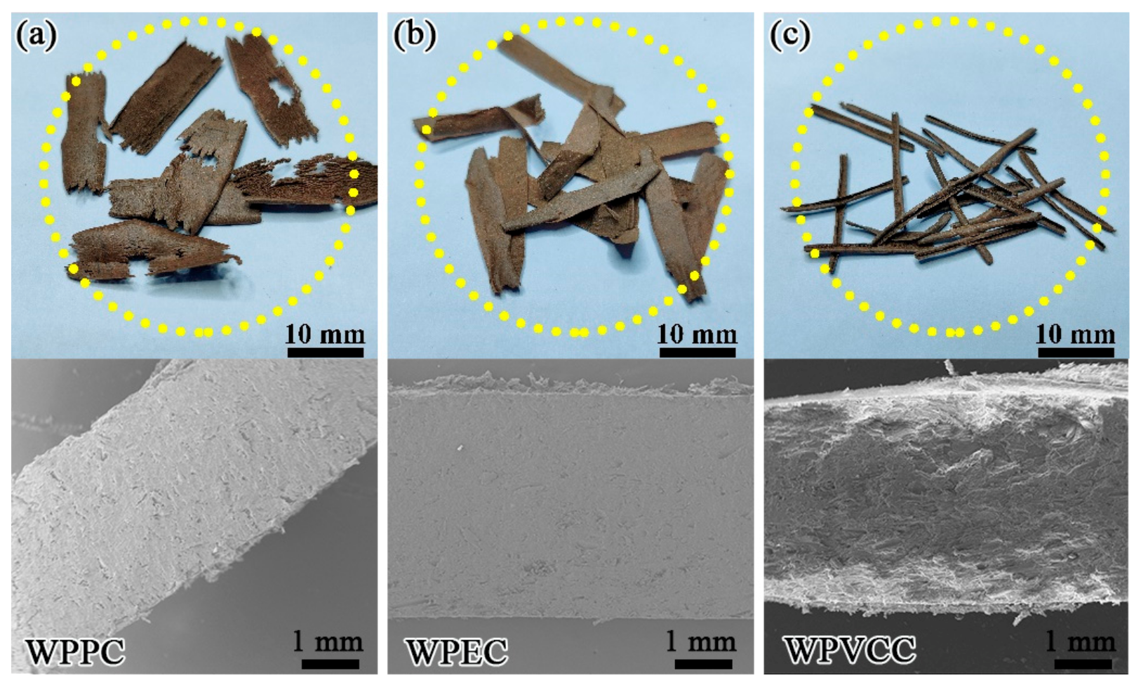
Cutting is a material removal process and as such, when the total force from the cutter exceeds the ultimate strength of the material of interest, material is removed by the cutter as chips of different shapes and sizes [9,10]. During WPC’s machining, only three types of chips were released at the optimal combination of cutting parameters (α = 2°, v = 9.0 m/s, Uz = 0.3 mm, and ap = 1.5 mm), namely semi-discontinuous ribbon chips, continuous ribbon chips, and needle chips (Figure 5). For the most part, these chips are similar in shape to those generated during orthogonal cutting of WPCs [11]. Upon closer inspection, the chips of WPPC were in the shape of flakes, some of which were broken. All WPPC chips resembled semi-discontinuous ribbon chips. The chips from WPEC were shaped in a continuous flake-like form, and were defined as continuous ribbon chips. Interestingly, unlike the ribbon chips from WPPC and WPEC, the chip shapes of WPVCC were needle-like (Figure 5).
Based on research into plastic-based material properties, PVC is known to have a lower toughness than PP and PE. Thus, when WPVCC was milled, the cutting layer was quickly broken, leading to the generation of needle chips because of the low elastoplasticity of WPVCC. PP being much harder than PE led to the formation of ribbon chips with a semi-discontinuous shape.
3.5. Tool Wear
Flank surface wear of the cemented carbide cutters used in this study was evaluated using scanning electron micrographs after a cutting distance of 500 m was completed (Figure 6). As can be clearly seen, the main wear patterns of cemented carbide cutters during machining of WPCs were chipping and flaking. Flaking is a severe wear pattern, wherein the original sharpness and appearance of the cutting edge change considerably, directly affecting the tool’s cutting stability and quality [24]. Furthermore, based on the degree of tool wear, it was observed that the radius of tool edge (r = 0.18 mm) when machining WPVCC was higher than those for WPEC (r = 0.13 mm) and WPPC (r = 0.09 mm). In other words, the wear of cutting tools when machining WPPC was more severe when compared with WPEC and WPVCC (Figure 6). It is known that tool wear is mainly affected by thermal-mechanical coupling [25]. As described in Section 2 in the present work, peripheral milling was adopted, which is an intermittent cutting process. Thus, the cutting edge periodically cuts into and withdraws from the workpiece. Repeated cycles of instantaneous impact force and periodic stress led to tool wear with different characteristics, namely flaking and chipping. As detailed above, the cutting forces and cutting temperatures when machining WPPC were both higher than those for WPEC and WPVCC. Consequentially, the most severe tool surface wear resulted from machining WPPC, followed by WPEC and WPVCC.
4. Conclusions
This work aimed to explore the cutting performance of wood-plastic composites based on cutting forces, cutting temperature, surface quality, chip formation, and tool wear. The main conclusions from this study based on a series of peripheral milling experiments using cemented carbide cutters are as follows:
- (1)
- Optimal cutting parameters for the three WPCs machining yielding the lowest surface roughness are 2° rake angle, 9.0 m/s cutting speed, 0.3 mm feed per tooth, and 1.5 mm cutting depth.
- (2)
- WPPC exhibited the highest cutting forces and cutting temperatures under the same cutting conditions, followed by WPEC and WPVCC.
- (3)
- Three types of chips were formed during machining of the three types of WPC, namely continuous ribbon chips (WPEC), semi-discontinuous ribbon chips (WPPC), and needle chips (WPVCC).
- (4)
- Tool wear when machining WPPC was more severe when compared to WPEC and WPVCC, with the dominant wear pattern for WPPC being chipping and flaking.
It is important to note that the focus of this work was on cutting forces, temperature, and chip and tool wear. Surface damage and morphology are also crucial parameters to evaluate the machinability of WPCs. In the future, special attention should be given to the machined surface to further increase value yield during the WPC manufacturing process.
Author Contributions
Conceptualization, Z.Z. and D.B.; methodology, W.X.; software, Z.W.; validation, X.G., J.W. and Z.Z.; formal analysis, Z.Z.; investigation, J.W., Z.Z. and Z.W.; resources, X.G.; data curation, J.W. and Z.W.; writing—original draft preparation, Z.Z. and D.B.; writing—review and editing, Z.Z. and D.B.; visualization, W.X.; supervision, D.B. and W.X.; project administration, X.G.; funding acquisition, X.G. All authors have read and agreed to the published version of the manuscript.
Funding
This work was supported by the National Natural Science Foundation of China [31971594], the Natural Science Foundation of the Jiangsu Higher Education Institutions of China [21KJB220009], the Technology Innovation Alliance of Wood/Bamboo Industry [TIAWBI2021-08], the Self-Made Experimental and Teaching Instruments of Nanjing Forestry University in 2021 [nlzzyq202101], and the International Cooperation Joint Laboratory for Production, Education, Research and Application of Ecological Health Care on Home Furnishing.
Institutional Review Board Statement
Not applicable.
Informed Consent Statement
Not applicable.
Data Availability Statement
Not applicable.
Conflicts of Interest
The authors declare no conflict of interest.
References
- Fabiyi, J.S.; Mcdonald, A.G. Effect of wood species on property and weathering performance of wood plastic composites. Compos. Part A Appl. Sci. Manuf. 2010, 41, 1434–1440. [Google Scholar] [CrossRef]
- Friedrich, D. Thermoplastic moulding of wood-polymer composites (WPC): A review on physical and mechanical behaviour under hot-pressing technique. Compos. Struct. 2021, 262, 113649. [Google Scholar] [CrossRef]
- HNg, P.; Lee, A.N.; Hang, C.M.; Lee, S.H.; Paridah, M.T. Biological durability of injection moulded wood plastic composite boards. J. Appl. Sci. 2011, 11, 384–388. [Google Scholar] [CrossRef]
- Fang, L.; Xiong, X.Q.; Wang, X.H.; Chen, H.; Mo, X.F. Effects of surface modification methods on mechanical and interfacial properties of high-density polyethylene-bonded wood veneer composites. J. Wood Sci. 2017, 63, 65–73. [Google Scholar] [CrossRef] [Green Version]
- Cui, Y.; Lee, S.; Noruziaan, B.; Cheung, M.; Jie, T. Fabrication and interfacial modification of wood/recycled plastic composite materials. Compos. Part A Appl. Sci. Manuf. 2008, 39, 655–661. [Google Scholar] [CrossRef]
- Mo, X.; Zhang, X.; Fang, L.; Zhang, Y. Research Progress of Wood-Based Panels Made of Thermoplastics as Wood Adhesives. Polymers 2022, 14, 98. [Google Scholar] [CrossRef]
- Li, R.; He, C.; Chen, Y.; Wang, X. Effects of laser parameters on the width of color change area of poplar wood surface during a single irradiation. Eur. J. Wood Wood Prod. 2021, 79, 1109–1116. [Google Scholar] [CrossRef]
- Li, R.; He, C.; Wang, X. Evaluation and modeling of processability of laser removal technique for bamboo outer layer. JOM J. Miner. Met. Mater. Soc. 2021, 73, 2423–2430. [Google Scholar] [CrossRef]
- Guo, X.; Li, R.; Cao, P.; Ekevad, M.; Cristóvão, L.; Marklund, B.; Grönlund, A. Effect of average chip thickness and cutting speed on cutting forces and surface roughness during peripheral up milling of wood flour/polyvinyl chloride composite. Wood Res. 2015, 60, 147–156. [Google Scholar]
- Guo, X.; Wang, J.; Buck, D.; Zhu, Z.; Guo, Y. Machinability of wood fiber/polyethylene composite during orthogonal cutting. Wood Sci. Technol. 2021, 55, 521–534. [Google Scholar] [CrossRef]
- Guo, X.; Ekevad, M.; Marklund, B.; Li, R.; Cao, P.; Grönlund, A. Cutting forces and chip morphology during wood plastic composites orthogonal cutting. BioResources 2014, 9, 2090–2106. [Google Scholar] [CrossRef] [Green Version]
- Shi, W.; Yan, M.; Zhe, W.; Yang, C. Experimental Evaluation on Shape and Control of Chip in Milling of PE WPC. Int. J. u-e-Serv. Sci. Technol. 2016, 9, 299–308. [Google Scholar]
- Pei, Z.; Zhu, N.; Gong, Y. A study on cutting temperature for wood–plastic composite. J. Thermoplast. Compos. Mater. 2009, 29, 1627–1640. [Google Scholar] [CrossRef]
- Hutyrova, Z.; Zajac, J.; Mital, D.; Botko, F.; Valicek, J. Wood filled plastics—Machining and surface quality. In Proceedings of the International Electronic Conference on Materials, Basel, Switzerland, 3 May 2016. [Google Scholar]
- Hutyrová, Z.; Zajac, J.; Michalik, P.; Mitaľ, D.; Duplák, J.; Gajdoš, S. Study of surface roughness of machined polymer composite material. Int. J. Polym. Sci. 2015, 2015, 303517. [Google Scholar] [CrossRef] [Green Version]
- Kong, Y.; Tian, X.; Gong, C.; Chu, P.K. Enhancement of toughness and wear resistance by CrN/CrCN multilayered coatings for wood processing. Surf. Coat. Technol. 2018, 344, 204–213. [Google Scholar] [CrossRef]
- Wei, W.; Li, Y.; Xue, T.; Li, Y.; Sun, P.; Yang, B.; Mei, C. Tool wear during high-speed milling of wood-plastic composites. BioResources 2019, 14, 8678–8688. [Google Scholar]
- Camposeco-Negrete, C. Optimization of cutting parameters for minimizing energy consumption in turning of AISI 6061 T6 using Taguchi methodology and ANOVA. J. Clean. Prod. 2013, 53, 195–203. [Google Scholar] [CrossRef]
- Tyo, J.S. Design of optimal polarimeters: Maximization of signal-to-noise ratio and minimization of systematic error. Appl. Opt. 2002, 41, 619–630. [Google Scholar] [CrossRef]
- Supadarattanawong, S.; Rodkwan, S. An Investigation of the Optimal Cutting Conditions in Parawood (Heavea Brasiliensis) Machining Process on a CNC Wood Router. Agric. Nat. Resour. 2015, 40, 311–319. [Google Scholar]
- Hu, W.G.; Chen, B.R.; Zhang, T.X. Experimental and numerical studies on mechanical behaviors of beech wood under compressive and tensile states. Wood Res. 2021, 66, 27–37. [Google Scholar] [CrossRef]
- Jin, D.; Wei, K. Machinability of Scots Pine during Peripheral Milling with Helical Cutters. BioResources 2021, 16, 8172–8183. [Google Scholar] [CrossRef]
- Hu, W.G.; Liu, Y.; Li, S. Characterizing Mode I Fracture Behaviors of Wood Using Compact Tension in Selected System Crack Propagation. Forests 2021, 12, 1369. [Google Scholar] [CrossRef]
- Djurković, M.; Milosavljević, M.; Mihailović, V.; Danon, G. Tool wear impacts on cutting power and surface quality in peripheral wood milling. Int. J. Wood Des. Technol. 2019, 8, 9–17. [Google Scholar]
- Wei, W.; Li, Y.; Xu, Y.; Yang, C. Research on tool wear factors for milling wood-plastic composites based on response surface methodology. BioResources 2021, 16, 151–162. [Google Scholar] [CrossRef]
Figure 1.
Measurements of (a) force by piezoelectric dynamometer, (b) cutting temperature by infrared imaging system.
Figure 1.
Measurements of (a) force by piezoelectric dynamometer, (b) cutting temperature by infrared imaging system.

Figure 2.
Experiment I: main effects of the experimental cutting factors on SNR values for surface roughness.
Figure 2.
Experiment I: main effects of the experimental cutting factors on SNR values for surface roughness.

Figure 3.
Experiment II: changes in dynamic cutting forces of (a) Ft and (b) Fn with different WPC types.
Figure 3.
Experiment II: changes in dynamic cutting forces of (a) Ft and (b) Fn with different WPC types.

Figure 4.
Experiment II: changes in (a) dynamic cutting temperature and (b) maximum cutting temperature with different WPC types.
Figure 4.
Experiment II: changes in (a) dynamic cutting temperature and (b) maximum cutting temperature with different WPC types.

Figure 5.
Experiment II: chip morphologies of (a) WPPC, (b) WPEC, and (c) WPVCC.

Figure 6.
Experiment II: flank wear of cemented carbide cutters during machining of (a) WPPC, (b) WPEC, and (c) WPVCC.
Figure 6.
Experiment II: flank wear of cemented carbide cutters during machining of (a) WPPC, (b) WPEC, and (c) WPVCC.


Table 1.
Material composition and properties of wood plastic composites obtained by four samples of each type.
Table 1.
Material composition and properties of wood plastic composites obtained by four samples of each type.
| WPC Type | Material Composition | Material Properties | ||||
|---|---|---|---|---|---|---|
| Plastic | WOOD FIBER | Moisture Content (%) | Flexural Strength (MPa) | Modulus of Elasticity (GPa) | Density (g/cm3) | |
| WPPC | PP | Poplar | 2.6 | 26.35 | 2.42 | 1.47 |
| WPEC | PE | 2.5 | 22.44 | 2.19 | 1.28 | |
| WPVCC | PVC | 2.9 | 20.08 | 2.02 | 0.93 | |
Table 2.
Tool geometries and properties.
| Tool Geometry | Material Properties | ||||
|---|---|---|---|---|---|
| Rake Angle | Clearance Angle | Cutter Diameter | Bending Strength | Thermal Conductivity | Hardness |
| 2° | 55° | 18 cm | 1.5 GPa | 76.2 W·m−1·K−1 | 88.3 HRA |
| 6° | |||||
| 10° | |||||
Table 3.
Experimental cutting factors and levels.
| Level | Experimental Cutting Factors | |||
|---|---|---|---|---|
| α (°) | v (mm/s) | Uz (mm/Z) | ap (mm) | |
| 1 | 2 | 3 | 0.1 | 0.5 |
| 2 | 6 | 6 | 0.2 | 1.0 |
| 3 | 10 | 9 | 0.3 | 1.5 |
Table 4.
Experiment I: SNR values of each experimental cutting factor during WPC milling at the different experimental cutting factor levels.
Table 4.
Experiment I: SNR values of each experimental cutting factor during WPC milling at the different experimental cutting factor levels.
| Level | α (°) | v (m/s) | Uz (mm/Z) | ap (mm) |
|---|---|---|---|---|
| 1 | −5.689 | −5.506 | −5.861 | −5.372 |
| 2 | −5.658 | −5.540 | −5.000 | −5.560 |
| 3 | −5.496 | −5.798 | −5.982 | −5.911 |
| Delta | 0.192 | 0.292 | 0.982 | 0.539 |
| Rank | 4 | 3 | 1 | 2 |
Publisher’s Note: MDPI stays neutral with regard to jurisdictional claims in published maps and institutional affiliations. |
© 2022 by the authors. Licensee MDPI, Basel, Switzerland. This article is an open access article distributed under the terms and conditions of the Creative Commons Attribution (CC BY) license (https://creativecommons.org/licenses/by/4.0/).
Share and Cite
MDPI and ACS Style
Zhu, Z.; Buck, D.; Wang, J.; Wu, Z.; Xu, W.; Guo, X. Machinability of Different Wood-Plastic Composites during Peripheral Milling. Materials 2022, 15, 1303. https://0-doi-org.brum.beds.ac.uk/10.3390/ma15041303
AMA Style
Zhu Z, Buck D, Wang J, Wu Z, Xu W, Guo X. Machinability of Different Wood-Plastic Composites during Peripheral Milling. Materials. 2022; 15(4):1303. https://0-doi-org.brum.beds.ac.uk/10.3390/ma15041303
Chicago/Turabian StyleZhu, Zhaolong, Dietrich Buck, Jinxin Wang, Zhanwen Wu, Wei Xu, and Xiaolei Guo. 2022. "Machinability of Different Wood-Plastic Composites during Peripheral Milling" Materials 15, no. 4: 1303. https://0-doi-org.brum.beds.ac.uk/10.3390/ma15041303
Note that from the first issue of 2016, this journal uses article numbers instead of page numbers. See further details here.