
Reader–Tag Commands via Modulation Cutoff Intervals in RFID Systems †


Network Engineering and Security Department, Jordan University of Science and Technology, Irbid 22110, Jordan
*
Author to whom correspondence should be addressed.
†
This paper is an extended version of our paper published in the proceedings of from the International Conference on Communications, Signal Processing and Their Applications (ICCSPA ’20), Sharjah, United Arab Emirates, 16–18 March 2021.
Future Internet 2021, 13(9), 235; https://0-doi-org.brum.beds.ac.uk/10.3390/fi13090235
Submission received: 15 August 2021
/
Revised: 13 September 2021
/
Accepted: 14 September 2021
/
Published: 16 September 2021
(This article belongs to the Special Issue Selected Papers from the International Conference on Communications, Signal Processing and Their Applications (ICCSPA ’20))
Abstract
:Radio frequency identification (RFID) technology facilitates a myriad of applications. In such applications, an efficient reader–tag interrogation process is crucial. Nevertheless, throughout reader–tag communication, significant amounts of time and power are consumed on inescapable simultaneous tag replies (i.e., collisions) due to the lack of carrier sensing at the tags. This paper proposes the modulation cutoff intervals (MCI) process as a novel reader–tag interaction given the lack of carrier sensing constraints in passive RFID tags. MCI is facilitated through a simple digital baseband modulation termination (DBMT) circuit at the tag. DBMT detects the continuous-wave cutoff by the reader. In addition, DBMT provides different flags based on the duration of the continuous-wave cutoff. Given this capability at the tag, the reader cuts off its continuous-wave transmission for predefined intervals to indicate different commands to the interrogated tag(s). The MCI process is applied to tag interrogation (or anti-collision) and tag-counting protocols. The MCI process effect was evaluated by the two protocols under high and low tag populations. The performance of such protocols was significantly enhanced with precise synchronization within time slots with more than 50% and more than 55.6% enhancement on time and power performance of anti-collision and counting protocols, respectively. Through the MCI process, fast and power-efficient tag identification is achieved in inventory systems with low and high tag mobility; alternatively, in addition to the rapid and power efficient interaction with tags, anonymous tag counting is conducted by the proposed process.
1. Introduction
Passive radio frequency identification (RFID) technology is the backbone of many applications that require cost-effective and prompt detection/identification of tagged objects [1,2,3,4]. Moreover, the technology is extended to several object tracking and localization [5,6,7,8].
In RFID technology, the typical system consists of readers and tags. Reader(s) emits an RF signal to the power and communicate with one or more tags. The tags harvest the reader’s continuous wave (CW) RF signal to turn on their processing integrated circuit [9]. Once on, the tag conveys its message to the reader by backscattering. In backscattering, the impedance of the tag’s antenna is modified to return, absorb, or shift the phase of the reader’s signal. Then, on the other side, the reader interprets the reflected, absorbed, or phase-shifted signals from the tag into a stream of binary bits [9].
Backscattering eliminates the need for a power-hungry transceiver at the tag at the expense of not sensing the media, not to mention the inability to decode and command from the reader while backscattering [9,10]. In other words, the communication link is a reader-dependent half-duplex link. The main drawback of such a link is having a deaf tag when it starts data backscattering, preventing the reader from silencing the tag if the received data is not needed or corrupted [9,11]. For example, if two or more tags reply simultaneously (i.e., during collision slots in interrogation protocols), sending a command from the reader to indicate the collision is worthless and will not be decoded by the backscattering tags.
Formerly, the modulation silencing mechanism (MSM) has been proposed to terminate the tag’s backscattering if a collision slot is detected in anti-collision protocols [12,13]. In addition, MSM allows for virtual media sensing by the tag. In MSM, if the reader wants a tag to stop its backscattering, it turns off CW transmission, and an analog-based circuit equips the tag to detect the drop in the voltage at the main capacitor due to the lack of CW energy harvesting. In MSM, a capacitor voltage detection circuit is placed at the RF frontend of the tag.
In this paper, we improve the modulation silencing process to facilitate three objectives:
- Replacing the CW detection circuit from the RF frontend to the digital part of the tag’s IC, namely, the digital baseband modulation termination (DBMT) circuit. This objective eases the fabrication process of the tag’s IC and reduces the power consumption of the previously current-driven and “power-hungry” operational amplifiers.
- Enabling not only the detection of CW cutoffs but also the periods of such cutoffs. This objective utilizes the DBMT circuit to provide multiple flags, and each flag indicates a specific period of the CW cutoff.
In the MCI process, as the tag can calculate different periods of CW “silence”, the reader cuts off CW for specific periods known to the tags. The tags then interpret these periods as commands depending on the triggered flag by the DBMT circuit. This capability is utilized in anti-collision and counting protocols. The MCI process is applied to tag interrogation (or anti-collision) and tag-counting protocols, which are prominent communication protocols in inventory systems. MCI is evaluated under high and low tag population, and the time (and consequently the power) performance of such protocols was significantly enhanced in anti-collision and counting protocols, respectively.
The rest of this paper is organized as follows. In Section 2, MSM is discussed with emphasis on its design limitations. In Section 3, the DBMT circuit design is proposed to target the first two improvement objectives. In Section 4, the MCI process is then proposed to target the third and final improvement objective. Finally, Section 5 evaluates the time efficiency of anti-collision and counting protocols, and the paper is concluded in Section 6.
2. Background and Motivation
Due to the simplicity of passive RFID tags, reader–tag communication is designed based on time division multiple access techniques [9,14,15]. For instance, the main protocols in anti-collision are TDMA-based, namely, ALOHA- and tree-based protocols [1,9,15]. Communicating over other multiple access techniques requires a more sophisticated air interface design at the tags. In TDMA, tags send/receive their data within specific periods (or slots). These slots are initiated by the reader, which sends given data (a command) followed by CW transmission. The tags decode the command and then reply by changing their antenna impedance to backscatter the reader’s CW. Consequently, the reader’s command may address zero, one, or more than one tag. Ideally, in TDMA, the command should address only one tag. Addressing two or more tags will cause interference at the reader (collision slots); on the other hand, addressing no tag will no replies (empty slots). Thus, both collision and empty slots waste the reader’s time and energy. Starting a new command by the reader during empty slots was proposed in [15], and it was called the early ending of empty slots. Nevertheless, starting a new command during collision slots is challenging.
Once a tag starts modulating its antenna impedance to backscatter the reader’s CW, it is not decoding any command. Therefore, during collision slots, the reader cannot stop two or more tags’ backscattering by sending a stop command. At the same time, the reader cannot stop CW transmission to save power, as part of the CW is harvested by the tag during backscattering. Hence, the reader is forced to wait until the tags finish their backscattering to start a new slot. This collision slot dilemma cannot be solved unless the tag is designed to decode commands while backscattering. In [9], MSM was proposed to solve this dilemma and save collision slots’ temporal and energy implications.
In collision slots, tags start their replies by backscattering a preamble sequence [15]. As the tags are not synchronized at the bit level, the received preamble at the reader will result from multiple interfered backscattering of the CW. In such a case, the reader in MSM halts CW transmission for a specific period. The tags, conversely, can detect CW availability through a simple circuit at the RF frontend, namely, the continuous wave absence detection (CWAD) circuit [13]. Nonetheless, the CWAD circuit has three main limitations that may render MSM ineffective: CWAD placement, initial voltage value dependency, and CWAD passive (current-driven) components.
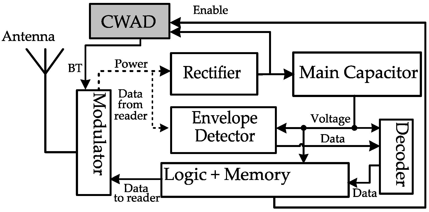
CWAD placement: CWAD was placed after the tag’s rectifier to sense the main capacitor voltage drop due to the lack of CW to be harvested, as depicted in Figure 1. Therefore, the absence of CW is detected (i.e., BT flag in Figure 1 is triggered) if the main capacitor voltage drops below a specific voltage. Unfortunately, this detection method leaves a wide chance of having the primary voltage drop to a level that may reset the tag’s state.
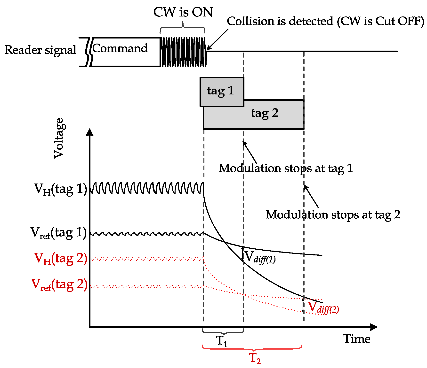
Initial voltage dependency: The initial voltage of the main capacitor before CW cutoff is not uniform for all tags due to different orientations and distances from the reader [9,15]. Hence, a predefined cutoff period that guarantees all tags to detect CW cutoff simultaneously is not feasible. This non-uniformity complicates protocol design by considering the most extended period that guarantees CW cutoff detection. However, this period is difficult to define for different types of readers, different antenna designs of tags, etc. An example of such a case is depicted in Figure 2, as two tags are sent simultaneously after the reader’s command. The two tags have different initial voltages at the main capacitor. The BT flag is triggered by the CWAD circuit if the rectifier’s output voltage becomes lower than the reference voltage level by a specific threshold denoted by . Thus, it is clear that Tag1 will detect the CW much earlier than Tag2.
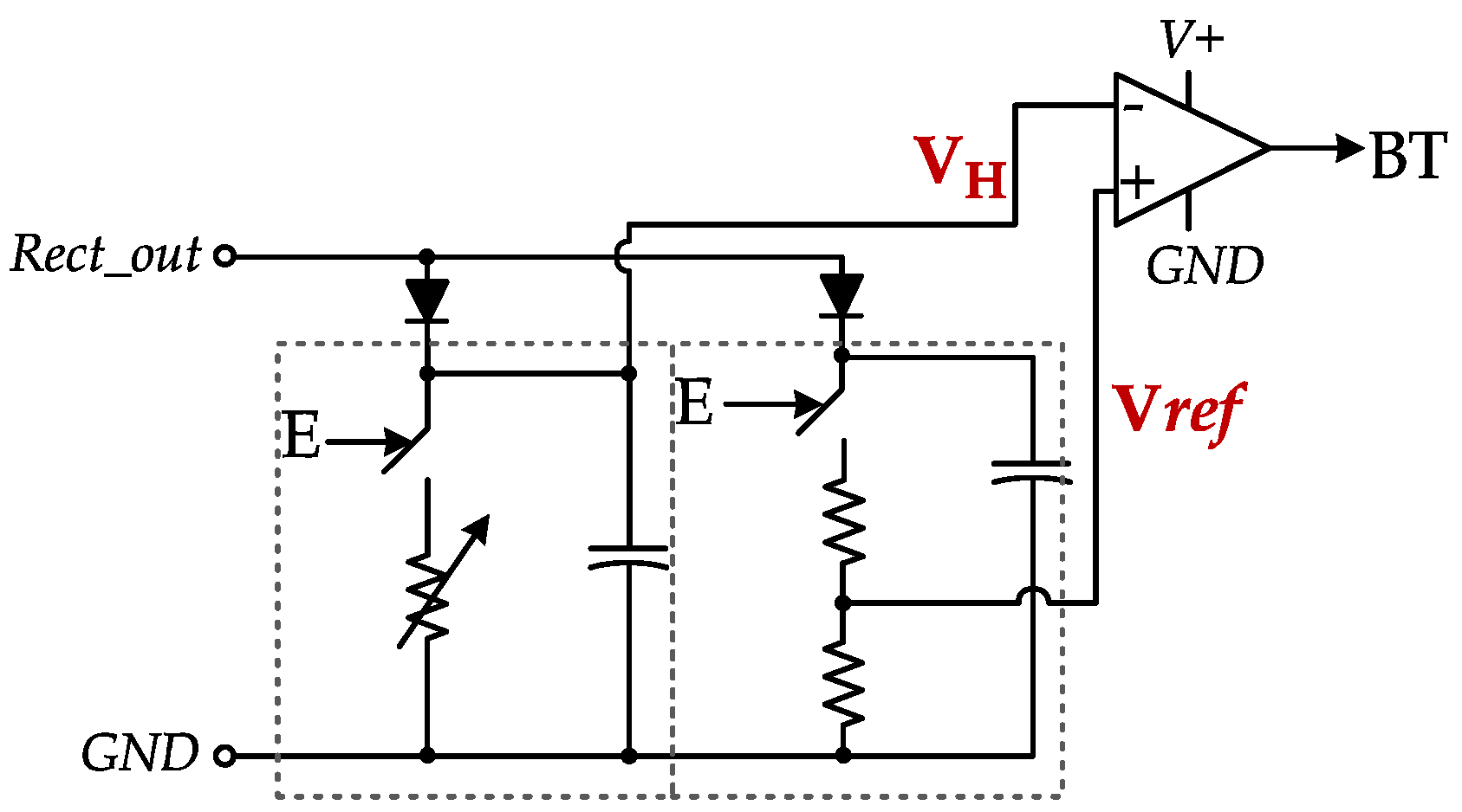
CWAD passive (current driven) components: The CWAD circuit was designed at the analog frontend with passive components and comparators as depicted in Figure 3. This design is challenging to the already power-constrained passive RFID tags.
In this paper, digital baseband modulation termination (DBMT) design is proposed to overcome the drawbacks of CWAD [13], with the following advantages:
- No modification to the RF interface of the tag.
- DBMT is digital and part of the logic module of the tag IC.
- DBMT provides a prompt and uniform interpretation of the CW cutoff or reduction, regardless of orientation/distance to the reader.
- DBMT enables the tag to interpret the CW cutoff and the period of this cutoff independently of the received power from the reader.
To further utilize the above features, a modulation cutoff intervals (MCI) process is proposed. The process utilizes multiple flags from DBMT to indicate different CW cutoff interval lengths. In the following two sections, the DBMT circuit and MCI process are presented, respectively.
3. Digital Baseband Modulation Termination
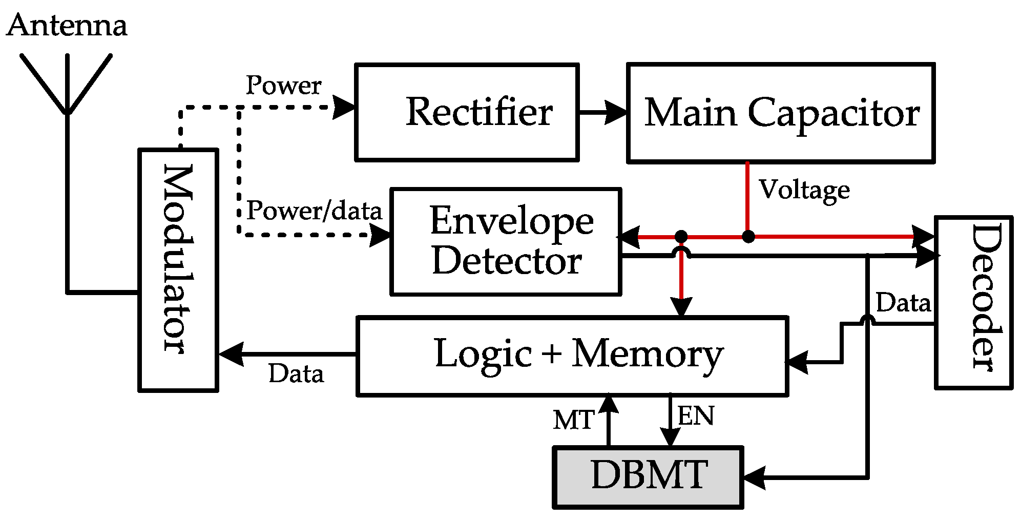
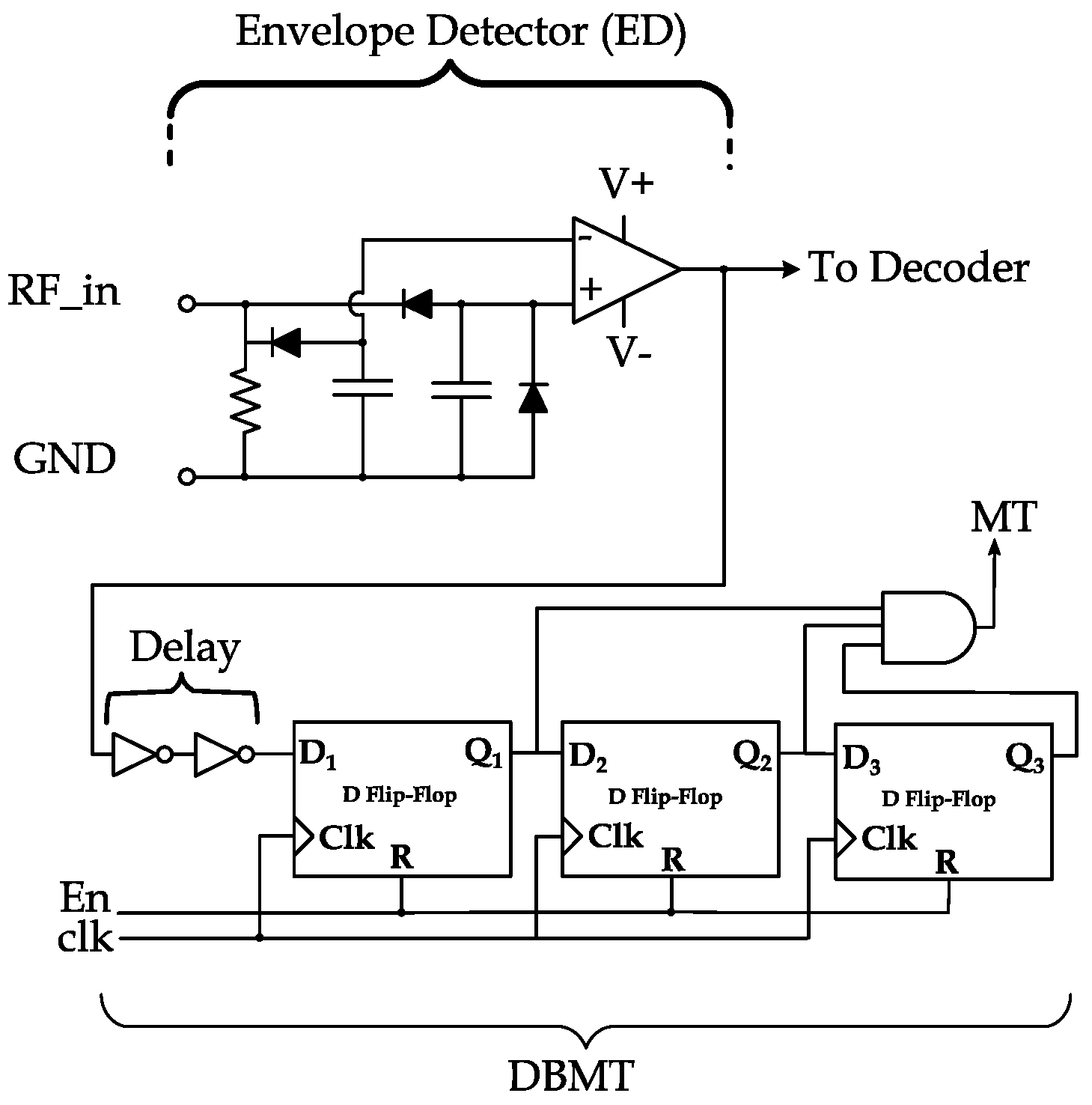
The first step in our design is relocating the detection circuit to the logic and memory module of the tag IC. The input of the digital baseband modulation termination circuit is fed from the output of the envelope detector (ED) module of the tag’s IC, as presented in Figure 4. The benefit of such relocation is taking advantage of the already implemented ED in all tags, which promptly follow the reader’s signal level. The ED is much faster in response than the rectifier (which is typically a modified version of the Dickson Charge Pump) with relatively large capacitors [9]. As the ED module produces a digital output (the output of the OpAmp in Figure 5), DBMT is implemented in digital (voltage-driven) logic gates and flip-flops.
3.1. DBMT Design
In Figure 5, the main components of the DBMT circuit and ED are shown. DBMT is enabled by the EN signal from the logic and memory module. DBMT, in its essential operation, consists of three synchronized D-flip flops (DFF) to latch and propagate the output of the ED. The output of the DBMT circuit is a flag noted as modulation termination (MT) flag, which is set if all DFFs output 1. Once set, the MT flag halts the impedance modulation for backscattering.
3.2. DBMT Operation
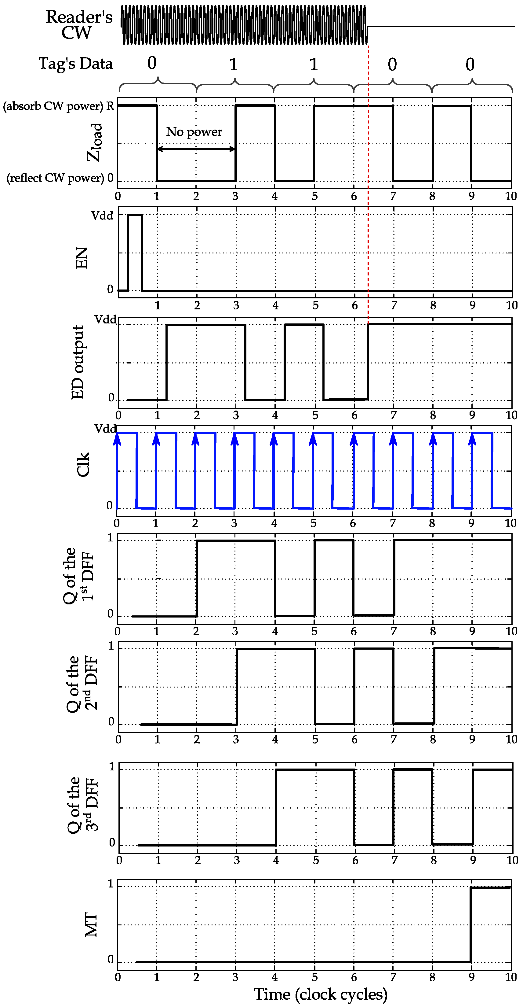
Once a reader command addresses a tag or multiple tags, backscattering is established to reply to the reader, and the EN signal is pulsed to initialize and enable the DBMT during backscattering. The EN pulse will reset the outputs (i.e., Qs) of the DFFs to zeros. The MT flag is triggered if the CW is off for more than two signal periods. The rationale behind selecting at least two signal periods is that tags are backscattering their data through pulse-interval encoding (PIE) with on–off keying modulation [16]. This PIE encoding involves changing the signal level between low and high intervals when backscattering 0 or 1 s, as shown in the illustration in Figure 6. Hence, since the tag may send 0 (represented as low-high) followed by 1 (represented by high-low), there might be two consecutive “high” intervals. During high intervals, the impedance of the tag (Zload in Figure 6) is set to reflect the CW signal, which means the rectifier harvests no power or a high level is shown at the output of the ED. Therefore, the case of sending 0 followed by 1 might indicate high output at the ED for an extended period, which might be interpreted as a CW cutoff. Therefore, MT is designed to be triggered after three consecutive low intervals in the ED. It is worth mentioning that if the tags use phase modulation (PM) [9,15] for backscattering, it absorbs power during low and high periods of the encoded data. Therefore, one DFF can be utilized in the DBMT of such tags.
In Figure 6, a timing illustration is provided for the primary control and output signals in DBMT for a tag during backscattering. The EN control signal initializes DBMT (i.e., resetting the DFF outputs). The tag is to send a stream of bits starting by 01100···. Sending the “0” bit is encoded by a low period followed by a high period. Conversely, to send this “0” bit to the reader, the antenna impedance (Zload) is changed to R during the low period to absorb the CW signal, then to “0” to reflect it. Note that when the CW is reflected, no power is rectified by the tag and the ED produces a high level (as the output of the ED is inverted). The first DFF will follow the ED after one clock cycle, the second DFF after two cycles, and the third DFF after three cycles. As in the PIE encoding, there will be no three successive high periods, and the DFFs will not simultaneously produce a “1” at their outputs (s).
The reader may detect corrupted reflections due to interference (collision), then it will cut off CW (within the first period of the 4th bit in Figure 6) for at least three clock cycles to cause the ED output to 1 and propagate it the outputs of the three DFFs. Once , , and are all “1”s, the MT flag is triggered, and the ongoing modulation will be terminated.
4. Modulation Cutoff Intervals Process
Since the envelope detector is used by the DBMT circuit to promptly follow the signal level at the antenna frontend, counting the clock cycles of which the CW is cut off becomes feasible. In other words, commands as a cutoff intervals can be applied in many protocols to indicate a multitude of actions required by the tag. The modulation cutoff intervals process is proposed to be applied in different RFID protocols. For example, in anti-collision protocols, a cutoff interval of a length of X can be designed to specify collision, while a cutoff interval of a length of Y can indicate a positive acknowledgment (ACK). Through the MCI process, the transmission of specific commands will be eliminated and replaced by a lookup table that matches cutoff intervals to their corresponding meaning/commands. In the following, we utilize the MCI process in anti-collision and counting protocols.
4.1. Anti-Collision Protocols
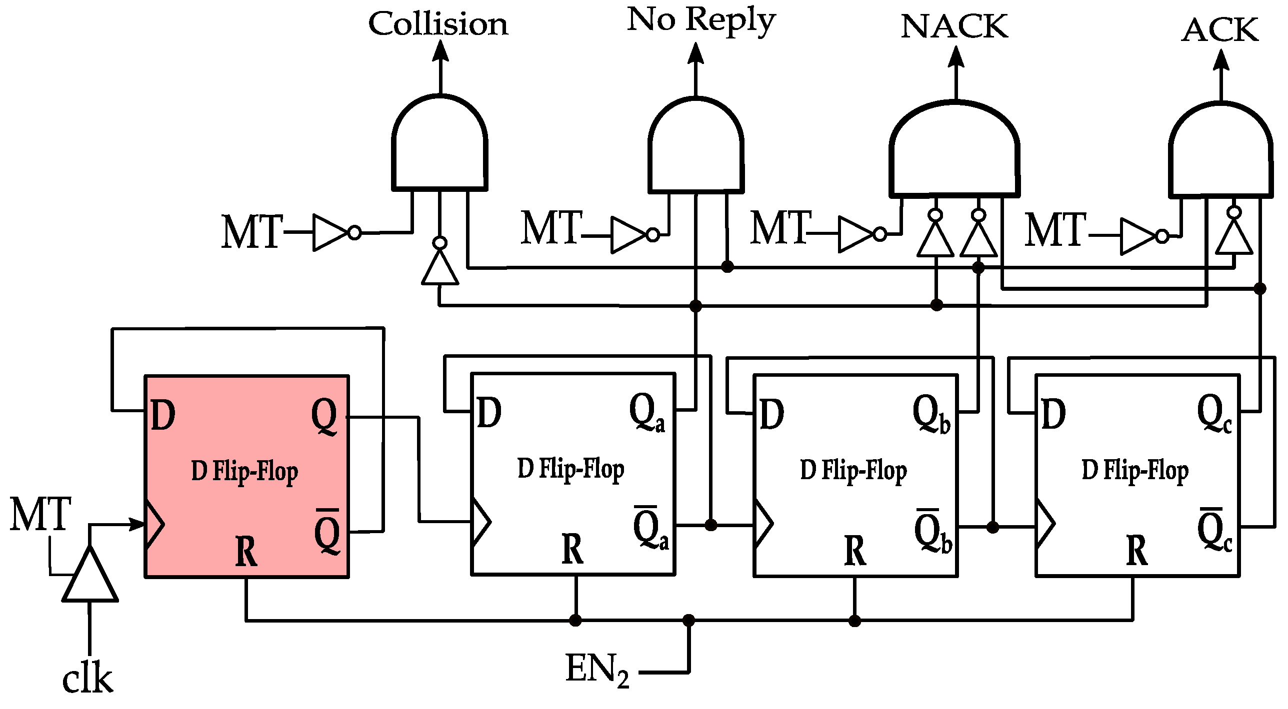
The MCI process is utilized in anti-collision protocols to indicate the four commands from the reader to the surrounding tags; namely, collision, no reply (empty), no acknowledgment (NACK), and acknowledgment (ACK) commands. During or after the tag(s) replies, the reader terminate its CW transmission for four possible intervals, , , and , where < < < . The intervals are interpreted as follows:
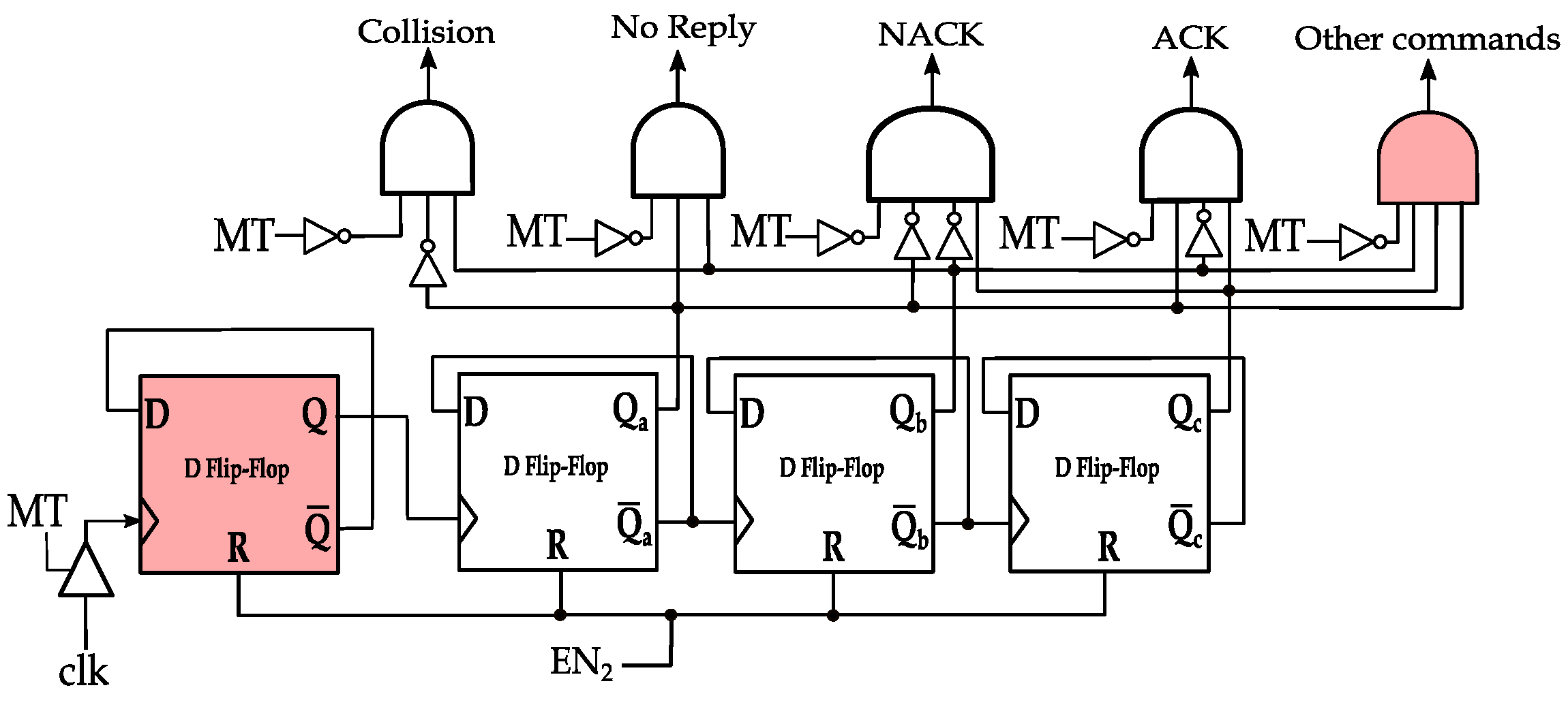
In Figure 7, MCI process command decoding circuit is shown for , , and of 4, 6, 8, and 10 clock cycles, respectively. Note that two clock cycles indicate the transmission of one symbol in PIE encoding, which is denoted by in the EPC standard documentation [16]. That is, , , and correspond to 2, 3, 4, and 5 symbol durations after MT assertion, respectively. The circuit is simply a ripple up-counter that is connected to the DBMT circuit. The counter is preceded by a frequency divider (the highlighted DFF in Figure 7) to output the number of symbols at which MT flag is asserted (i.e., high). If the count is two (i.e., ) and CW is resumed, the MT flag will no longer be high. The leftmost AND gate will assert flag, and a Collision command is assumed. Alternatively, flag is asserted if the count is three and CW is resumed, indicating an empty slot command. flag is asserted after CW resuming and the count is four (i.e., ), indicating a NACK command. Finally, if the count is five and the CW is resumed, will be asserted, and an ACK command is assumed. Following the CW transmission resumption, the control signal EN2 is pulsed to reset the counter for the next slot. Note that the assertion of the MT flag requires three clock cycles (1.5 symbol duration); therefore, are asserted after 7, 9, 11, and 13 clock cycles, respectively.
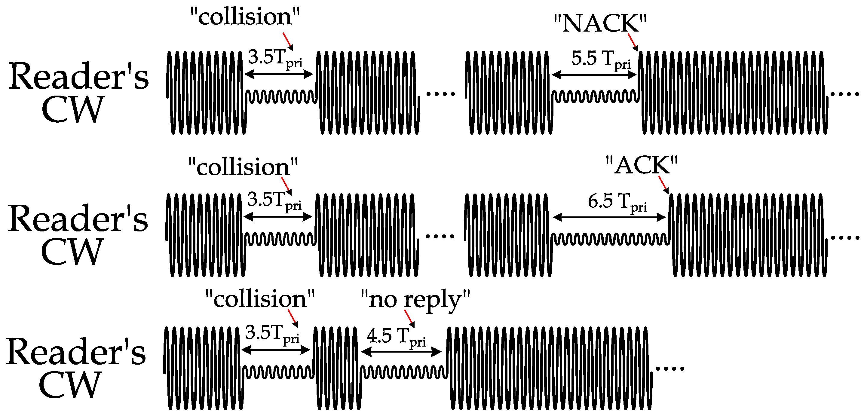
An example is illustrated in Figure 8 of the above commands. In the top waveform, the reader detects a collision (corrupted data that does not follow PIE encoding), stops the CW for 7 clock cycles (3.5 ), and then resumes its CW transmission. The received reply after that CW resumption was from a single tag, but for some reason, it has an erroneous CRC; the reader then negatively acknowledges the transmission by stopping the CW for 11 clock cycles (5.5 ). In the middle waveform in Figure 8, the data are received from a single tag after a collision slot, and the CRC was correct. Hence, the reader acknowledges the tag’s transmission by stopping the CW for 13 clock cycles (6.5 ). In the bottom waveform of Figure 8, no reply is detected from any tag after the collision (since in standardized anti-collision protocols, tags decide randomly to reply or not to reply). Therefore, the reader cuts off the CW for nine clock cycles to indicate an empty (no reply) slot and the beginning of a new slot.
MCI provides prompt feedback to the tags on the status of the ongoing transmission during the time slot and eliminates the need for guard periods between tag transmission and reader commands. Therefore, with MCI, collision and empty slots are significantly shortened compared to traditional collision and empty slots resolution. The above values of the cutoff periods are selected for illustrating the process; however, the general rule is to select the cutoff periods that are long enough to trigger the proper command at the tags but not too long to cause a significant power drop.
4.2. Counting Protocols
The MCI process can also be utilized in counting protocols in which the actual IDs of the tags are not necessary. The main concern of counting protocols is the number of single reply slots, which indicates the number of tags. Therefore, MCI can be applied to indicate three commands: NACK (indicating multiple tag reply slots), ACK (indicating a single reply slot), and no reply (empty slot). Consequently, the same MCI process circuit (shown in Figure 7) can be used to indicate these three commands. After initializing the tags to start the counting process, in any slot:
- If the preamble (a standardized bit pattern that is sent by the tags before sending their data) is received error-free in a given slot, the reader stops its CW for seven clock cycles to indicate a single slot.
- If the preamble is received incorrectly, the reader stops its CW for nine clock cycles to indicate a collision slot.
- Finally, if the time gap in the standard passed with no tags replying, the reader stops its CW for eleven clock cycles to indicate an empty slot.
In the MCI process, the tag reaction is adaptive based on the protocol that is under execution. For example, as shown above, stopping the CW for seven clock cycles may indicate a collision slot in anti-collision protocols or a single slot in counting protocols. Another advantage of the MCI process is its compatibility with explicit (traditional) commanding if needed. For example, in some protocols, the reader may send commands with specific data to the tags, not only the ones illustrated in the figure above. In such a case, the MCI process circuit can dedicate a specific cutoff interval, for example, a cutoff for 15 clock cycles, to inform the tag to expect an explicit data/command from the reader, as shown in Figure 9.
5. Performance Evaluation
5.1. Anti-Collision Protocols
In this section, the MCI process is applied to two main anti-collision protocols, probabilistic (ALOHA-based) and deterministic (tree-based) protocols. The MCI process effect on the performance of these protocols is evaluated for 40 sets of tag populations, starting from 100 tags up to 4000 tags (with an increment of 100 tags). In our evaluation, all the timing values are based on EPC standardized specifications (reader symbol duration of 25 μs, PIE encoding, and divide ratio of 8) [16].
Note that there will be a specific number of collision, empty, and single slots by the end of any identification process. Ideally, all slots will be single slots; however, this scenario is not possible due to a lack of communication between the tags. Therefore, all identification protocols aim at minimizing the number of non-valuable slots (collision and empty slots) to reduce the identification time and reader power consumption. In addition, the MCI process further reduces the effect of these non-valuable slots by ending them early.
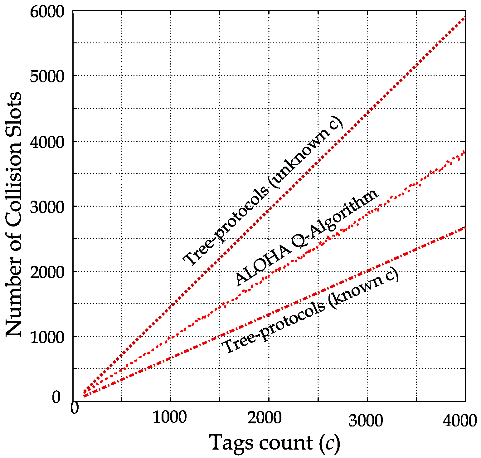
In probabilistic protocols, the number of collision slots depends on the total slots (frame size) that the tag competes to transmit their IDs within. If the frame is larger than the tag population, empty slots and single slots will be dominant. Similarly, frames that are smaller than the tag population will be dominated by collision and single slots. In the standardized identification protocols, the Q-Algorithm is used to maintain an equal proportion of collision, single, and empty slots by adaptively changing the frame size [17,18], as shown in Figure 10. For example, if 2000 tags are identified, around 6000 slots will be used by the end of the identification process, of which collision, single, and empty slots are roughly 2000 each. In other words, two-thirds of the identification process is wasted on empty and collision slots, where the MCI process effect is accentuated.
In deterministic (tree-based) protocols, the total number of collision and empty slots depends on the tag population’s pre-knowledge [14,19]. Therefore, the ratio of collision and empty slots to the total slots consumed in the identification process will be smaller if the tag population is known when compared to an unknown tag population.
In such deterministic protocols, the advanced knowledge of the tag population allows for query optimization while traversing the tree of tag IDs. This optimization aims at reaching single slots (the leaves in the tree) while skipping the tree’s internal nodes (which cause collision and empty slots). The total number of collision slots in the tree-based protocols for different tag populations is plotted in Figure 10.
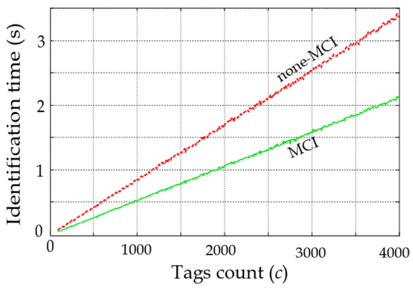
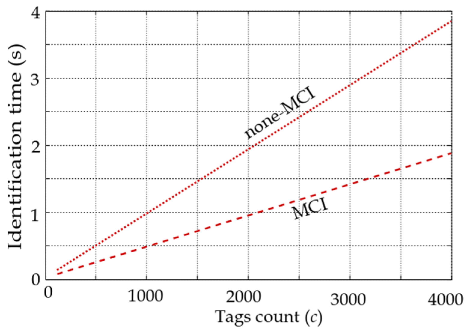
The performance of the identification protocols is evaluated based on the average identification time for different tag populations with and without the MCI process. Figure 11 and Figure 12 show average identification time after simulating probabilistic and deterministic (with known and unknown tag population) protocols under EPC-standardized timing [16]. In Figure 11, the average identification time for the Q-algorithm is shown with a speedup of 35.9% with the MCI process. Consequently, since the reader is transmitting CW and data during the identification process [9,14,15], 35.9% of the power consumption is saved by the MCI process.
In Figure 12, the average identification times for different tag populations in the deterministic tree-based protocol for unknown tag populations are shown. The reported results are the simulation of this protocol with and without the MCI process based on standardized timing [16]. The speedup of the MCI process is 50.1% compared to the none-MCI (standardized slot structure) process. A similar speedup is perceived with 41.4% of the MCI process over the non-MCI process when the tag population is known.
5.2. Counting Protocols
Similar to anti-collision protocols, the MCI process effect on the performance of counting protocols is evaluated for 40 sets of tag populations, starting from 100 tags up to 4000 tags (with an increment of 100 tags). In our evaluation, all the timing values are based on EPC-standardized specifications [16]. The MCI process significantly enhances the counting speed as it reduces all three types of slots. The different slot times based on the standard timing [16] and based on the MCI process are listed in Table 1.
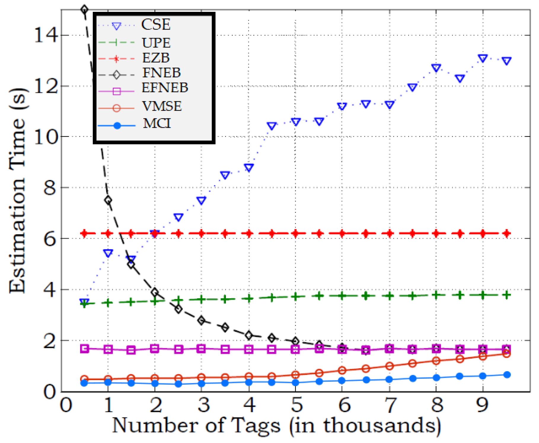
The MCI process is applied to the variance and modulation silencing-based estimations (VMSE) algorithm [20]. The performance of the MCI process is compared to the combined simple estimator (CSE) [21], the unified probabilistic estimator (UPE) [22], and the enhanced zero-based (EZB) estimator [22], FPNE estimator [23], and variance and modulation silencing-based estimations (VMSE) [20]. In Figure 13, the average counting times were plotted for counting with a 5% confidence interval (the average over 100 simulation runs) for tags that count from 1000 to 9500 tags.
The MCI process facilitates significant time saving and, consequently, reader power saving. It is worth mentioning that the reported results for counting with a confidence interval of 5%; however, if more accurate estimation is needed, the number of slots will increase dramatically in CSE [21] and UPE [22]. Note that the MCI process achieves the exact tag count in much less time than other population estimators. Compared to the most effecint algorithm (VMSE with standardized timing), the MCI process achieves more than 55.6% when counting large tag populations. At low and high tag populations, the MCI process is faster than CSE by 15.5 and 12.3 times, respectively.
6. Conclusions
In this paper, a new time slot reduction process is proposed. The MCI process depends on the DBMT circuit to interpret different CW cutoff intervals from the reader as commands. The DBMT circuit is placed within the logic and memory module of the tag (i.e., the baseband) to provide a prompt and accurate reaction to the reader CW cutoff. The MCI process facilitates the interpretation of different commands based on the number of clock cycles the MT flag from the DBMT is asserted. This process results in a substantial reduction of non-valuable time slots. The MCI process is applied in probabilistic and deterministic anti-collision protocols and in tag-counting protocols. In anti-collision protocols, the identification time and power efficiency are reduced by more than 50% and 41% for both probabilistic and deterministic protocols, respectively. In tag-counting protocols, a significant time reduction in counting specific tag populations is achieved compared to other counting protocols. The implications of such figures of merit will allow for faster and more energy-efficient identification protocols, which will be helpful in mobile and static inventory systems. In addition, since a portion of the tag reply is utilized for counting, the tags’ anonymity is preserved by this process. This also leads us to investigate the MCI process in the authentication protocol as a future research investigation.
Author Contributions
Conceptualization, A.Y.A.; methodology, A.Y.A. and M.A.M.; software, A.Y.A. and M.A.M.; validation, A.Y.A.; formal analysis, A.Y.A.; investigation, A.Y.A. and M.A.M.; resources, A.Y.A.; data curation, A.Y.A.; writing—original draft preparation, A.Y.A.; writing—review and editing, M.A.M.; visualization, A.Y.A.; supervision, A.Y.A.; project administration, A.Y.A. Both authors have read and agreed to the published version of the manuscript.
Funding
This research received no external funding.
Institutional Review Board Statement
Not applicable.
Informed Consent Statement
Not applicable.
Data Availability Statement
Not applicable.
Conflicts of Interest
The authors declare no conflict of interest.
References
- Jiang, Z.; Li, B.; Yang, M.; Yan, Z. LC-DFSA: Low Complexity Dynamic Frame Slotted Aloha Anti-Collision Algorithm for RFID System. Sensors 2020, 20, 228. [Google Scholar] [CrossRef] [Green Version]
- Su, J.; Sheng, Z.; Hong, D.; Leung, V.C.M. An efficient sub-frame based tag identification algorithm for UHF RFID systems. In Proceedings of the 2016 IEEE International Conference on Communications (ICC), Kuala Lumpur, Malaysia, 22–27 May 2016; pp. 1–6. [Google Scholar] [CrossRef]
- Oliveira, L.; Rodrigues, J.J.P.C.; Kozlov, S.A.; Rabêlo, R.A.L.; de Albuquerque, V.H.C. MAC Layer Protocols for Internet of Things: A Survey. Future Internet 2019, 11, 16. [Google Scholar] [CrossRef] [Green Version]
- Zhang, L.; Xiang, W. An energy- and time-efficient M-ary detecting tree RFID MAC protocol. In Proceedings of the 2015 IEEE International Conference on Communications (ICC), London, UK, 8–12 June 2015; pp. 2882–2887. [Google Scholar] [CrossRef]
- Zhang, J.; Wang, X.; Yu, Z.; Lyu, Y.; Mao, S.; Periaswamy, S.C.; Patton, J.; Wang, X. Robust RFID Based 6-DoF Localization for Unmanned Aerial Vehicles. IEEE Access 2019, 7, 77348–77361. [Google Scholar] [CrossRef]
- Zhao, R.; Zhang, Q.; Li, D.; Chen, H.; Wang, D. PRTS: A Passive RFID Real-Time Tracking System under the Conditions of Sparse Measurements. IEEE Sens. J. 2018, 18, 2097–2106. [Google Scholar] [CrossRef]
- Li, J.; Feng, G.; Wei, W.; Luo, C.; Cheng, L.; Wang, H.; Song, H.; Ming, Z. PSOTrack: A RFID-Based System for Random Moving Objects Tracking in Unconstrained Indoor Environment. IEEE Internet Things J. 2018, 5, 4632–4641. [Google Scholar] [CrossRef]
- Alma’aitah, A.Y.; Eslim, L.M.; Hassanein, H.S. Tag Localization with Asynchronous Inertial-Based Shifting and Trilateration. Sensors 2019, 19, 5204. [Google Scholar] [CrossRef] [PubMed] [Green Version]
- Dobkin, D. The RF in RFID: Passive UHF RFID in Practice; Newnes: Newton, MA, USA, 2007. [Google Scholar]
- Boyer, C.; Roy, S. Communication and RFID: Coding, Energy, and MIMO Analysis. IEEE Trans. Commun. 2014, 62, 770–785. [Google Scholar] [CrossRef]
- Chakraborty, R.; Roy, S.; Jandhyala, V. Revisiting RFID Link Budgets for Technology Scaling: Range Maximization of RFID Tags. IEEE Trans. Microw. Theory Tech. 2011, 59, 496–503. [Google Scholar] [CrossRef] [Green Version]
- Alma’aitah, A.; Hassanein, H.S.; Ibnkahla, M. Tag Modulation Silencing: Design and Application in RFID Anti-Collision Protocols. IEEE Trans. Commun. 2014, 62, 4068–4079. [Google Scholar] [CrossRef]
- Alma’aitah, A.Y.; Hassanein, H.S.; Ibnkahla, M. Rapid tag collision resolution using enhanced continuous wave absence detection. In Proceedings of the 38th Annual IEEE Conference on Local Computer Networks—Workshops, Sydney, Australia, 21–24 October 2013; pp. 861–867. [Google Scholar] [CrossRef]
- Klair, D.K.; Chin, K.; Raad, R. A Survey and Tutorial of RFID Anti-Collision Protocols. IEEE Commun. Surv. Tutor. 2010, 12, 400–421. [Google Scholar] [CrossRef] [Green Version]
- Cole, P. Fundamentals in Radio Frequency Identification; Technical Report; Auto-ID Res. Lab.: Adelaide, Australia.
- EPC Radio-Frequency Identification Protocols Class-1 Gen-2 UHF RFID Protocol for Communications at 860 MHz–960 MHz, EPCglobal Std. Rev. 1.2.0. October 2008. Available online: https://www.gs1.org/sites/default/files/docs/epc/Gen2_Protocol_Standard.pdf (accessed on 15 August 2021).
- Arjona, L.; Landaluce, H.; Perallos, A.; Onieva, E. Dynamic Frame Update Policy for UHF RFID Sensor Tag Collisions. Sensors 2020, 20, 2696. [Google Scholar] [CrossRef] [PubMed]
- Xie, L.; Sheng, B.; Tan, C.C.; Han, H.; Li, Q.; Chen, D. Efficient Tag Identification in Mobile RFID Systems. In Proceedings of the 2010 Proceedings IEEE INFOCOM, San Diego, CA, USA, 14–19 March 2010; pp. 1–9. [Google Scholar] [CrossRef] [Green Version]
- Chen, Y.-H.; Chen, Y.-A.; Huang, S.-R. A Mobility Aware Binary Tree Algorithm to Resolve RFID Jam and Bottleneck Problems in a Next Generation Specimen Management System. Micromachines 2020, 11, 755. [Google Scholar] [CrossRef] [PubMed]
- Alma’aitah, A.Y.; Hassanein, H.S.; Ibnkahla, M. Efficient and anonymous RFID tag counting and estimation using Modulation Silencing. In Proceedings of the 2012 8th International Wireless Communications and Mobile Computing Conference (IWCMC), Limassol, Cyprus, 27–31 August 2012; pp. 515–520. [Google Scholar] [CrossRef]
- Kodialam, M.; Nandagopal, T. Fast and reliable estimation schemes in RFID systems. In Proceedings of the 12th Annual International Conference on Mobile Computing and Networking, Los Angeles, CA, USA, 23–29 September 2006. [Google Scholar]
- Kodialam, M.; Nandagopal, T.; Lau, W.C. Anonymous Tracking Using RFID Tags. In Proceedings of the IEEE INFOCOM 2007—26th IEEE International Conference on Computer Communications, Anchorage, AK, USA, 6–12 May 2007; pp. 1217–1225. [Google Scholar] [CrossRef]
- Han, H.; Sheng, B.; Tan, C.C.; Li, Q.; Mao, W.; Lu, S. Counting RFID Tags Efficiently and Anonymously. In Proceedings of the 2010 Proceedings IEEE INFOCOM, San Diego, CA, USA, 14–19 March 2010; pp. 1–9. [Google Scholar] [CrossRef]
Figure 1.
CWAD circuit after the rectifier in the general components of a passive RFID tag [10].
Figure 1.
CWAD circuit after the rectifier in the general components of a passive RFID tag [10].

Figure 2.
Different CW cutoff detection times between two tags due to the difference in the initial rectifier output voltage, .
Figure 2.
Different CW cutoff detection times between two tags due to the difference in the initial rectifier output voltage, .

Figure 3.
CWAD circuit consisting mostly of passive components [10].
Figure 3.
CWAD circuit consisting mostly of passive components [10].

Figure 4.
CWAD DBMT circuit location within typical passive RFID components.

Figure 5.
DBMT module and its placement after the ED.

Figure 6.
Timing diagram example of the DBMT outputs for a tag sending PIE encoded stream of bits starting by 01100··· and CW cutoff by the reader at the 4th bit.
Figure 6.
Timing diagram example of the DBMT outputs for a tag sending PIE encoded stream of bits starting by 01100··· and CW cutoff by the reader at the 4th bit.

Figure 7.
MCI process in anti-collision protocols with PIE encoding.

Figure 8.
Three different scenarios of reader commands in anti-collision protocols with MCI process.
Figure 8.
Three different scenarios of reader commands in anti-collision protocols with MCI process.

Figure 9.
MCI process in anti-collision protocols with PIE encoding to accommodate MCI commands and other commands that are sent explicitly not through the MCI.
Figure 9.
MCI process in anti-collision protocols with PIE encoding to accommodate MCI commands and other commands that are sent explicitly not through the MCI.

Figure 10.
Total number of collision slots vs. different tag populations (from 100 to 4000 tags).

Figure 11.
Average identification time for different tag population in the standardized Q-Algorithm.
Figure 11.
Average identification time for different tag population in the standardized Q-Algorithm.

Figure 12.
Average identification time for different unknown tag populations in the deterministic tree-based algorithm.
Figure 12.
Average identification time for different unknown tag populations in the deterministic tree-based algorithm.

Figure 13.
Comparison of average counting/estimation time of tags under different protocols.


Table 1.
Slot length in μs with and without MCI process.
| Slot Type | Collision | Single | Empty |
|---|---|---|---|
| Standardized slot length [16] | 117.2 | 145.3 | 70 |
| MCI process on standardized slot length | 78 | 87 | 70 |
Publisher’s Note: MDPI stays neutral with regard to jurisdictional claims in published maps and institutional affiliations. |
© 2021 by the authors. Licensee MDPI, Basel, Switzerland. This article is an open access article distributed under the terms and conditions of the Creative Commons Attribution (CC BY) license (https://creativecommons.org/licenses/by/4.0/).
Share and Cite
MDPI and ACS Style
Alma’aitah, A.Y.; Massad, M.A. Reader–Tag Commands via Modulation Cutoff Intervals in RFID Systems. Future Internet 2021, 13, 235. https://0-doi-org.brum.beds.ac.uk/10.3390/fi13090235
AMA Style
Alma’aitah AY, Massad MA. Reader–Tag Commands via Modulation Cutoff Intervals in RFID Systems. Future Internet. 2021; 13(9):235. https://0-doi-org.brum.beds.ac.uk/10.3390/fi13090235
Chicago/Turabian StyleAlma’aitah, Abdallah Y., and Mohammad A. Massad. 2021. "Reader–Tag Commands via Modulation Cutoff Intervals in RFID Systems" Future Internet 13, no. 9: 235. https://0-doi-org.brum.beds.ac.uk/10.3390/fi13090235
Note that from the first issue of 2016, this journal uses article numbers instead of page numbers. See further details here.