
SRv6-Based Edge Service Continuity in 5G Mobile Networks †


1
Department of Information Engineering, University of Pisa, 55022 Pisa, Italy
2
Department of Information Engineering, University of Florence, 50139 Florence, Italy
*
Author to whom correspondence should be addressed.
†
This paper is an extended version of our paper published in IEEE Conference on Network Function Virtualization and Software Defined Networks (NFV-SDN 2023), “Ensuring Lossless Workload Migration at the Edge with SRv6”, Dresden, Germany, 7–9 November 2023.
Future Internet 2024, 16(4), 138; https://0-doi-org.brum.beds.ac.uk/10.3390/fi16040138
Submission received: 22 March 2024
/
Revised: 14 April 2024
/
Accepted: 17 April 2024
/
Published: 19 April 2024
(This article belongs to the Special Issue Edge Intelligence: Edge Computing for 5G and the Internet of Things)
Abstract
:Ensuring compliance with the stringent latency requirements of edge services requires close cooperation between the network and computing components. Within mobile 5G networks, the nomadic behavior of users may impact the performance of edge services, prompting the need for workload migration techniques. These techniques allow services to follow users by moving between edge nodes. This paper introduces an innovative approach for edge service continuity by integrating Segment Routing over IPv6 (SRv6) into the 5G core data plane alongside the ETSI multi-access edge computing (MEC) architecture. Our approach maintains compatibility with non-SRv6 5G network components. We use SRv6 for packet steering and Software-Defined Networking (SDN) for dynamic network configuration. Leveraging the SRv6 Network Programming paradigm, we achieve lossless workload migration by implementing a packet buffer as a virtual network function. Our buffer may be dynamically allocated and configured within the network. We test our proposed solution on a small-scale testbed consisting of an Open Network Operating System (ONOS) SDN controller and a core network made of P4 BMv2 switches, emulated using Mininet. A comparison with a non-SRv6 alternative that uses IPv6 routing shows the higher scalability and flexibility of our approach in terms of the number of rules to be installed and time required for configuration.
1. Introduction
Emerging applications demand efficient network infrastructure and protocols, as well as the collaboration of network and computing elements. 5G network technology meets these requirements, as it features qualities such as programmability, low latency, high bandwidth, network, and context awareness [1]. 5G expands the previous generation capabilities, defining new application areas: Enhanced Mobile Broadband (eMBB), Ultra-Reliable Low-Latency Communications (URLLC), and Massive Machine-Type Communications (mMTC) [2,3].
5G is a technology that relies on small cells, which have low-power and short-range transmissions. This feature enables higher bandwidth and reliability, but also leads to more frequent handovers due to the limited coverage [4,5]. The ability of the client to move seamlessly is, in fact, a fundamental feature of 5G networks.
Edge computing is a key concept for 5G applications that require very low latency, such as augmented reality, virtual reality, autonomous vehicles, and the Internet of Things (IoT) [6]. Edge computing is characterized by its wide and pervasive distribution across geographic areas, close to the end user. The proximity of computing facilities is the key factor that enables ultra-low latency, high bandwidth, and security. Edge services, i.e., those services running in edge data centers, may then require migration across edge sites to support user mobility. When the user changes her/his location, the edge site that hosts the user-assigned edge service may become too distant and cause higher latency. In this situation, another edge data center may be closer. The edge service should “follow” the client to preserve the Quality of Service (QoS). If services are stateful, moving the service along with its internal state is required. In this context, one way to achieve this mechanism is to wrap the service in virtual machines or containers and migrate the instance from the original edge site to a target one using existing methods to smoothly transfer the whole package [7].
The European Telecommunications Standards Institute Industry Specification Group (ETSI ISG) worked in the last decade to create a standardized, open, multi-vendor, and multi-access edge computing environment. The ETSI specifies the elements required to enable applications to be hosted in a multi-vendor multi-access edge computing (MEC) environment [8]. The MEC architecture provides cloud computing capabilities and a distributed environment at the edge of the network. The system consists of MEC Hosts dislocated at the edge of the network and connected through the underlay communication infrastructure. It provides advantages in terms of delay, network traffic, and data localization. The ETSI MEC has been identified as the key technology for supporting low-latency edge services in 5G networks. The ETSI MEC architecture provides a system orchestration mechanism that enables the management of service instances and their dynamic association with the user equipment (UE) [9]. The orchestration oversees the selection of the best MEC Host where a service instance should run in order to guarantee the application requirements’ satisfaction. It is also in charge of triggering the proper network configuration through the 5G core (5GC) in a centralized manner. The ETSI MEC environment also supports the service continuity required by user mobility in 5G networks. The MEC system, based on the information exchanged with the 5GC network entities, verifies which is, at any time, the best MEC Host for an edge service. To guarantee the latency constraints, instance migration may be triggered [10]. MEC can guarantee service continuity by employing various techniques such as DNS and device–application interface solutions. Most of the proposed methods, however, require the active involvement of the client [11].
In line with the 5G requirements for a network that is highly scalable, maintainable, and programmable [12], Segment Routing over IPv6 (SRv6) has been recently proposed as the new data plane for 5GC [13,14]. SRv6 provides flexibility, programmability, scalability, and has great potential for further development, which are essential features of 5G networks. SRv6 Network Programming allows integrating functions, implemented as virtual network functions (VNFs), as part of the network node packet processing. SRv6 also facilitates the dynamic reconfiguration of the network, enabling seamless service continuity when edge services are migrated to follow their mobile 5G users. Enabling seamless service continuity means letting the client reach the edge service in its new location, while guaranteeing qualitative and quantitative requirements. For what concerns qualitative aspects, the service must be reached transparently to the client application logic, which is achieved through SRv6 by keeping the same IP address for the migrated service. Moreover, no packets should be lost during the service migration process. With respect to quantitative requirements, the application should not suffer from any significant impairment in terms of, for example, experiencing latency or throughput. In addition, SRv6 simplifies the network protocol stack in 5G scenarios. Finally, SRv6 supports the centralized control plane [15], allowing an easy integration with the 5G-MEC environment.
Let us consider the scenario of Figure 1, where MEC Hosts are deployed in proximity to the gNBs to run latency-constrained services. A UE can move and access the network through a different gNB. After the handover, the MEC system may decide to relocate the edge service associated with the moved user to a different MEC Host. Subsequently, a network reconfiguration is required to allow the UE to seamlessly reach the edge service in its new location. In this context, we propose a solution for lossless workload migration, based on buffering implemented as a VNF that is dynamically allocated in the network and by the network.
Our approach relies on the integration between MEC and 5G, using an SRv6-based data plane, and on the strategic implementation of SRv6 Network Programming. Leveraging the MEC environment enables the allocation of edge services and their dynamic relocation to accommodate user mobility. The SRv6 Network Programming paradigm provides the capabilities required to ensure service continuity within the ETSI MEC framework through dynamic reconfiguration of the network, by means of an SDN controller, and through the integration of buffering as a VNF within the packet-processing pipeline.
A preliminary version of this work was presented in [16]. This work extends it by integrating our SRv6-based, service continuity solution into the 5GC data plane and the ETSI MEC architecture. Specifically, this work makes the following four-fold contribution:
- It presents a converged MEC-based architecture for service continuity in 5G with an SRv6 programmable data plane.
- It defines an SRv6 End.Buffer behavior for guaranteeing lossless workload migration in SRv6-compliant 5G networks.
- To ensure compatibility with non-SRv6 5G network components, it introduces a new End.M.GTP6.D.Buffer behavior acting as a VNF at the border between such components and the SRv6 5GC network.
- It describes a Proof-of-Concept (PoC) implementation of the proposed system based on P4 devices. We evaluated our solution over a limited-scale test environment and compared the performance against a non-SRv6 alternative that uses IPv6 routing.
The remainder of this paper is organized as follows. Section 2 introduces background content on SRv6 Network Programming. Next, Section 3 reports the related work in the field. Then, Section 4 presents our converged 5G and MEC architecture and related procedures, whereas Section 5 describes our SRv6-based migration solution that is integrated in the above 5G-MEC context. In Section 6, we detail the experimental analysis of the proposed solution. Finally, Section 7 concludes the paper.
2. Background on SRv6 Network Programming
2.1. SRv6 Architecture
Segment Routing (SR) is a source-routing-based tunneling method enabling packet steering through a network via a list of segments. It accommodates the Equal-Cost Multipath (ECMP) aspect of IP and offers compatibility with both distributed and centralized control paradigms for segment construction and network optimization [17,18].
The data plane of SR architecture outlines the encoding of segments to be incorporated into a packet and defines the forwarding semantics for each segment, i.e., how a node should process a packet based on the segment. Two different implementations of the SR architecture are available: SR over MPLS and SRv6.
The control plane of SR architecture outlines the method for distributing segments across network nodes. Additionally, it establishes a mechanism for instructing nodes on how to apply the segment list to a packet or a flow.
Each segment is identified by a Segment IDentifier (SID), which is an MPLS label in the case of MPLS implementation or an IPv6 address in the case of SRv6 implementation. Segments are divided into Node SIDs, Adjacency SIDs, and Service SIDs. In the first type, the segment identifies a node, which means that a packet must be forwarded to that node through the shortest path. The Adjacency SID is a segment identifying the link over which the packet must be forwarded. These kinds of SIDs have local scope, limited to the node that processes it. Finally, the Service SID is a kind of segment identifying a function that must be executed on a node. That SID contains information on both the function and the node that must execute it. In this work, we utilize SRv6 implementation, which is currently the most commonly employed.
IPv6 architecture can embed SR functionalities through an extension header, called Segment Routing Header (SRH), which is a type of Routing Header [19]. Figure 2 depicts the SRv6 header structure. In SRv6, each segment is an IPv6 address, which represents an action(s) that a network node should execute, for example, forwarding the packet to a next hop or running a VNF. The SID currently designated as the packet’s destination address is said to be the active segment. The SRH is composed of the list of segments, entered in reverse order, i.e., the last segment to be reached will be placed at index 0, while the first one at the last index. The SRH contains other fields, such as Last Entry, which states the index (starting from 0) of the last element in the segment list, i.e., the first one to be used, and Segment Left, which specifies the index of the active segment.
The SR architecture comprises three types of nodes: source, endpoint, and transit [19]. The source node is the one in charge of embedding the SRH in the packet. As detailed later, the source node may either embed the SRH in the original IPv6 packet, called inline SRH, or encapsulate the original packet into an outer IPv6 header with the SRH extension, called encapsulated SRH. In the case of encapsulation, the SRH may not be necessary. This happens when the number of segments in the list is equal to one. In this case, it is enough to insert that segment as the destination address of the outer IPv6 header. In the case of the inline SRH, the source node must modify the original IPv6 header fields as follows. It sets as the destination address the last segment of the SRH segment list. It increases the payload length by the SRH size. It sets as the Next Header the Routing Header. It also needs to set the Next Header field of the SRH to the Next Header field value of the original IPv6 packet. In the case of the encapsulated SRH, the source node must fill the outer IPv6 header fields as follows. It sets as the source address the current node address, and as the destination address, the last segment of the SRH segment list. Its Next Header field value must be equal to 34, which is the Routing Header. Finally, the payload length must be set to the SRH size plus the original IPv6 packet size. The transit node is any node that forwards a packet based on its IPv6 destination address, without processing the SRH. The packet destination address is not a node’s locally configured SID. The transit node may even be non-SRv6 capable, but it must be IPv6 capable. Finally, the endpoint node is a node receiving a packet whose IPv6 destination address is a locally instantiated SID. It will process the SRH and apply the instruction coded into the received SID.
The source node is the one in charge of steering packets based on a policy, i.e., a list of segments, which are instructions [20]. The policy can be identified through an IPv6 address, called Binding SID (BSID). A given policy may be executed by different source nodes. Note, however, that each source node must use a different BSID from other source nodes, to indicate that same policy. When a source node receives a packet whose destination address matches with a locally instantiated BSID, it applies the corresponding policy. In other words, the source node inserts in the packet the list of segments associated with that policy [20,21,22]. A source node must instantiate a different BSID for each policy it wants to implement. The BSID is a key element in the SR architecture, providing scalability and network opacity. It also allows the exploitation of the same SR policy by different entities, because setting a specific BSID as the destination address is enough to obtain the execution of a policy.
2.2. SRv6 Network Programming
SRv6 Network Programming is a framework that allows the encoding of a sequence of instructions in an IPv6 packet. Each instruction is identified by an SID and is executed on the node that has instantiated that SID. Those instructions can range from simple packet forwarding to more complex functions [23]. Functions are called behaviors in the SRv6 Network Programming domain.
An SRv6 Service SID is a 128-bit address structured as LOC:FUNC:ARG. The number of bits composing each part are not pre-established; the only constraint is that the total length cannot exceed 128. LOC identifies the locator, i.e., the endpoint node, and it is the routable part. FUNC is an opaque identifier of the behavior locally instantiated by the node identified by LOC. It is bounded to the SID. Finally, the ARG field contains the behavior’s arguments. The SID structure is usually defined by the SRv6 domain provider, which establishes the number of bits to be used for each part and assigns the locator to each node. Then, each node or a central entity can assign the bits related to the function and argument parts. In a distributed scenario, each SID must be advertised together with a codepoint, mapping the SID to a specific function. Codepoints and their meaning must be known by all the SRv6-enabled devices within the domain. In a centralized scenario, the SIDs will be configured and installed by the central controller, which also instructs the source node to enter a segment list.
In [23], a set of standard behaviors is defined; however, SRv6 Network Programming has the flexibility to support the association of any function with an SID, as shown in [24,25,26]. In what follows, we give an overview of the standard behaviors exploited in this work. In Section 2.2.1, we describe H.Encaps.Red, which is used to tunnel the packet through the 5GC, encapsulating it into an outer IPv6 header along with an additional SRv6 sub-header. In Section 2.2.2, we illustrate H.Insert, which, instead, adds an SRv6 sub-header to the original IPv6 packet. Finally, in Section 2.2.3, we detail the End behavior, applied by each SRv6 endpoint.
2.2.1. H.Encaps.Red
This behavior is applied by the source node in the case of the SRH-encapsulated version. When the source node receives a packet whose destination address matches with a locally instantiated BSID associated with the H.Encaps.Red behavior, it does the following. Firstly, it encapsulates the packet into an outer IPv6 header. Then, if the segment list to be entered is more than one element long, it embeds the SRH into the IPv6 outer header. The first segment to be reached is not included in the SRH; instead, it is just set as the destination address. Based on that, the Segment Left field of the SRH will be the index of the last element in the list plus one, because the active segment is not included in the SRH. In addition, the header length is 128 bits shorter. If, instead, the segment list to be entered contains just one element, the SRH is not needed: the element will be placed in the destination address of the outer IPv6 header. Finally, the outer IPv6 header fields are properly set, and the packet is forwarded.
2.2.2. H.Insert
This behavior is applied by the source node in the case of the inline SRH version. When the source node receives a packet whose destination address matches with a locally instantiated SID associated with the H.Insert behavior, it does what follows. Firstly, it embeds the SRH into the IPv6 header. Then, it sets the last segment of the list as the packet destination address. Finally, the SRH and IPv6 header fields are properly set, and the packet is forwarded.
Differently from the H.Encaps.Red, where the final destination (e.g., the service address) is in the inner IPv6 header, in the H.Insert case, that address must be included in the segment list. The latter requires removing the SRH at the penultimate segment to make the procedure transparent or if the service is SRv6 unaware. The H.Insert behavior is less scalable compared to the H.Encaps.Red because the same SRv6 policy (i.e., list of segments) cannot be applied to multiple services. The reason is that in the case of H.Insert, the service address must be included in the SRH segment list. In the case of H.Encaps.Red instead, using an outer IPv6 header, the service address can be left in the destination address field of the inner IPv6 header. H.Encaps.Red allows the exploitation of the same SRv6 policy for all the packets that require the same list of segments.
2.2.3. End
The End behavior actions are performed by all the endpoints, and most of the custom behaviors are extensions of this one. When a node receives a packet whose destination address matches with its locally instantiated End SID, if the Segment Left field of the SRH is not zero, the node does the following actions. Firstly, it decreases by one the hop limit field of the outermost IPv6 header. Then, it decreases by one the Segment Left by one. Subsequently, it takes the new active segment and sets it as the IPv6 destination address. Finally, it forwards the packet. If, instead, the Segment Left field of the packet is zero, the SRH must be removed, using one of the available flavors. In this work, we exploit the Ultimate Segment Decapsulation (USD).
When a node applying the End behavior finds the Segment Left field equal to zero, it does the following. Firstly, it removes the outer IPv6 header. Then, it forwards the packet based on the inner IPv6 destination address.
3. Related Work
The service continuity problem with workload migration is addressed in the literature at different protocol stack layers [27]. The authors in [24] propose a three-layer solution to guarantee no loss when a virtual machine is migrated within the same cloud data center to achieve load balancing. They exploit SRv6 to embed source and target servers into pre-established logical paths. They defined three SRv6 behaviors; however, only the routers directly connected with the virtual machine can apply them because they must be able to detect the virtual machine status. Moreover, the approach can be used only in a single data center because the routers must have knowledge of the local network. Finally, the packet buffer cannot be flexibly placed. The work in [24] cannot support service continuity during inter-data center migration, as it relies on local network awareness.
Another network-layer solution is provided by the work in [28], where the Locator/Identifier Separation Protocol (LISP) is used in conjunction with SRv6. The approach allows the managing of the path migration for the Service Function Chains (SFCs) in a distributed edge environment, with the aim of facilitating user mobility. The LISP is exploited to associate a service identifier with its location, introducing additional and unnecessary complexity. SRv6 is indeed a flexible framework able to inherently offer functionalities similar to those provided by the LISP, without requiring a separate mapping for a service locator/identifier. Some works in the literature have extended the SRv6 Network Programming model proposed in [23]. The authors in [25] introduce a new behavior to direct incoming traffic toward the egress node along the path ensuring the highest throughput. The authors in [26] proposed a new SRv6 behavior that enables in-network programming. The new behavior allows the execution of any possible function in eBPF by encoding the latter in a segment. Contributions to SRv6 Network Programming outlined by [25,26] are not applicable to ensuring service continuity during workload migration within an edge computing environment.
For what concerns solutions at the transport layer, the authors in [29] enhance the QUIC protocol on the server side to maintain connections after service relocation; however, they do not preserve the original IP address and therefore need to handle this aspect. Alternatively, service continuity can be ensured at the link layer, as demonstrated in [30,31], where VXLAN and NVGRE are, respectively, employed for this purpose. However, these solutions are not suitable in the distributed edge environment.
The service continuity problem has also been addressed at the application level. The ETSI MEC [11] proposes a solution, also exploited by [32], where the DNS and the client are involved in the service continuity procedure. The client, at each HTTP transaction, must open a new TCP connection and query the DNS to have the service location. In addition, the DNS must notify the client each time the service moves to a different MEC Host. The ETSI MEC [11] provides another solution at the application layer to guarantee service continuity. When a client is able to directly interact with the MEC system, it can be notified of the MEC application instance address by the MEO. This solution, however, requires modifying the client to make the interaction possible.
The authors in [33] propose a solution based on SDN to ensure service continuity in the 5G-MEC scenario. They guarantee the connection persistency by maintaining the original IP address after service relocation. The solution, however, considers a legacy 5G network, where the GTP-U encapsulation is used, and no SRv6 support is provided.
4. Architecture and Procedures for MEC-Based Mobile Services
In this section, we describe a converged 5G and MEC architecture that combines elements from both domains. Our focus is on how these components interact and enable efficient service delivery and their seamless migration at the network edge. We consider a modified version of the 5G MEC architecture proposed in [9]. Our architecture is shown in Figure 3. Using Figure 3 as a reference, the Radio Access Network (RAN) serves as the bridge between user equipments (UEs) and the cellular network. It encompasses base stations (gNBs in 5G terminology) and handles radio-resource management, modulation, and demodulation.
The 5GC forms the central part of the 5G system, providing connectivity between the RAN and other data networks. The data plane (or user plane in 5G terminology) is composed of one or more User Plane Functions (UPFs) that process and forward user data to/from external data networks. UPFs can be deployed as part of the external data networks, such as an MEC deployment, although remaining logically a component of the 5GC. In current 5GC architectures, the communication between the RAN and the UPF, and among UPFs, is handled by the GPRS Tunneling Protocol User Plane (GTP-U). However, several studies and standardization efforts from both 3GPP and IETF are proposing SRv6 for substituting GTP-U toward a full-IP 5GC [13,14]. We follow this approach, and we consider the user plane to be composed of SRv6-capable UPFs. We note that additional SRv6 nodes can be deployed between UPFs, e.g., to embed virtualized network functions (VNFs) or for traffic engineering purposes [13]. In the following, we will refer to both these nodes and UPFs as SRv6 nodes. In Section 4.2, we will present the procedures related to configuring SRv6 nodes for forwarding IP packets through the data plane.
The 5GC control plane is composed of several functions controlling and configuring both the core and access network aspects. Each function offers one or more services to other functions in the networking through a service bus, following a so-called Service-Based Architecture (SBA).
From the perspective of this work, the functions of interest are the Access and Mobility Management Function (AMF), Session Management Function (SMF), and the Network Exposure Function (NEF). The AMF handles UE registration and session management and is responsible for user mobility management, authentication, and security. The SMF controls session establishment, modification, and termination, and is responsible for routing data between UEs and external networks. In the considered architecture, the AMF and SMF will be responsible for configuration, respectively, in the gNBs and in SRv6 nodes. As far as the IP packets forwarding is concerned, we will assume the SMF to configure it through a dedicated SDN controller. In more detail, as reported in [34], the SMF sees the SDN controller as a UPF. Communication between the SDN controller and the SMF is enabled via the N4 interface. The SDN controller, instead, configures the forwarding rules on SRv6 nodes. The utilization of an SDN controller allows us to decouple the SMF and the network devices, creating a hybrid SDN network wherein different protocols can be employed for device configuration [35]. Following this approach, the SMF is not required to interact with devices directly; instead, it only needs to communicate with the SDN controllers using a standard 3GPP interface. Finally, the NEF provides APIs for exposing network capabilities to external systems, e.g., letting them request network reconfiguration to the AMF or SMF.
In a typical deployment, both the 5G control plane components and the SDN controller should be replicated so that they do not constitute a single point of failure. They must provide high availability and they must ensure consistency.
Exploiting SDN controllers for routing rules configuration also facilitates the adaptability of the solution for hybrid networks. Each SDN controller is responsible for configuring its network components using network-specific protocols.
The MEC system acts as an external data network that is accessible through the 5GC. It is composed of several MEC Hosts, deployed at the network edge, and providing virtualized resources. MEC Hosts allow the deployment of MEC applications, which provide services for the end user, including, e.g., augmented reality, video analytics, and IoT applications. In the augmented reality domain, a typical scenario where a stateful service is run in edge servers is assisted surgery [36]. Considering the IoT, a mobile application can be used to remotely control sensors and actuators through a service running on an MEC Host. Video analytics applications can be exploited for autonomous driving [37].
Several MEC Hosts are managed by a logically centralized MEC Orchestrator (MEO), which manages the deployment, scaling, and lifecycle of MEC applications across multiple MEC Hosts. It optimizes resource utilization based on user demands and network conditions. In this work, we have not studied policies and algorithms for selecting the service instance in order to optimize the performance and resources. However, considering the growing adoption of a new paradigm, known as computing-aware traffic steering (CATS), in future work, we intend to study orchestration solution matching that new vision. In CATS, networking and computing capabilities and their dynamic status must be jointly taken into consideration to carry out the proper decision in terms of traffic steering and service instance selection [38]. The MEO decisions may require the 5GC to be configured accordingly. For this purpose, the MEC communicates with the AMF and SMF through the NEF.
The integration of the above components may introduce new vulnerabilities in the system, each one inherited by the added elements. In this respect, within the literature, there are several works that describe and solve the possible security threats of 5G, SRv6, MEC, and SDN controllers. The potential risks and typical attacks on SDN networks are comprehensively outlined in [39], which also presents solutions for protecting the network. The work in [40] presents the most common security issues in 5G networks, providing possible countermeasures as well. ETSI MEC vulnerabilities are described in [41], also illustrating the solutions available in the literature. Finally, the authors in [42] deal with security and risks in SRv6 networks.
4.1. IPv6 Addressing Convention and Reference Scenario
We now present a possible allocation of IPv6 addresses for the different entities, which we use throughout the paper. The used addressing convention has been inspired by [43].
The pool C:0::/32 is reserved for services. The client is allocated the pool A:0::/32. The 5GC network devices are allocated addresses from the B:0::/32 pool, as Table 1 shows. In more detail, the gNB addresses are assigned from B:0:1::/48, whereas the addresses of the SRv6 nodes are allocated from B:0:0::/48. As suggested by [23], the SID comprises three components: the locator, the function, and the arguments. For a given device, the locator remains consistent across all behaviors and is constructed from the node identifier, e.g., B:0:0:1::/48 being the locator, each implemented behavior has an address whose first 48 bits are B:0:0:1::.
In Section 4.2 and in Section 5, we will employ four distinct behaviors. Two behaviors are taken from [23], whereas two new behaviors, End.Buffer and End.M.GTP6.D.Buffer, are defined in this work to support the lossless mobility in SRv6-based 5G networks. The End behavior, as defined in [23], is allocated the prefix B:0:0:<nodeid>:E:/80 and requires no arguments.
Regarding the two new behaviors, the End.Buffer, which will be explained in Section 5.2.1, is denoted by B:0:0:<nodeid>:B::/80. The End.M.GTP6.D behavior, defined in [13] and identified by the BSID B:0:0:<nodeid>:G000:<args>::/80, requires arguments to establish the SRv6 policy, i.e., to delineate the list of segments to be encapsulated in the SRH. Finally, the End.M.GTP6.D.Buffer behavior, which will be described in Section 5.2.2, is identified by the BSID B:0:0:<nodeid>:GB00:<args>::/80. It requires arguments to identify the SRv6 policy, i.e., to understand the list of segments to be encapsulated in the SRH before executing the buffering function.
We conclude this section by illustrating a reference network topology, reported in Figure 4, which is used as a reference in Section 4.2 and Section 5 for describing the allocation and migration procedures. A UE can be either a mobile device or an IoT device. A UE is connected to the base station gNB1, which accesses the 5GC network via SR Endpoint1. The service instance of the UE runs on MEC Host1 and is deployed in the form of containers. MEC Host1 is in turn connected to the 5GC through SR Endpoint3. The 5GC control plane, prompted by the MEO, configures the system’s routing rules via the AMF and SMF. The SMF communicates with the SDN controller to implement rules in the SRv6 nodes.
Since the UE has mobility capabilities, a handover, e.g., from gNB1 to gNB2 could occur. Assuming a non-roaming handover, the client retains its original IPv6 address. The MEC architecture provides mechanisms to support service instance migration and information transfer between MEC Hosts [44]. Upon notification from the 5GC regarding the UE mobility, the MEC system can initiate the migration of the corresponding service from MEC Host1 to MEC Host2. The migration in this case is the procedure that allows a running container to be moved from one host to another [45]. Uplink packets traverse the 5GC via SR Endpoint2 and exit through SR Endpoint4. As soon as migration is triggered, a network update to reroute packets toward the new destination is enforced.
4.2. SRv6-Based Path Allocation
Based on the architecture presented so far, we now discuss the configuration of a 5GC network in the case of MEC-based services. The procedures are based on [13], which considers two operation modes: Enhanced Mode and Enhanced Mode with Unchanged gNB Behavior. The first mode belongs to a full SRv6-aware 5G core network, where the SRv6 domain is extended to the gNBs. The gNBs tunnel the packet across the 5GC network through an IPv6-SRv6 encapsulation. The second concerns the case of a 5G network with SRv6-unaware gNBs. This second mode guarantees the retro compatibility, by instructing the first SRv6 node of the 5GC network, called the Ingress Router, to remove the GTP-U encapsulation and add the SRv6 one. As anticipated in Section 4, GTP-U is a protocol that allows the establishment of a tunnel between the RAN and the 5GC to carry user information. A GTP-U tunnel is uniquely identified by a Tunnel Endpoint Identifier (TEID). Using Figure 4 as a reference, we describe the SRv6-based path allocation procedure in both modes.
The path allocation procedure is triggered by the first request for an edge service by a client. Initially, the MEC system instantiates a container to host the requested service, assigning it an IPv6 address from the appropriate pool. This IPv6 address is retained throughout the container’s lifecycle. Hence, any subsequent migration does not alter its assigned address. Subsequently, the MEO triggers the AMF and the SMF to configure routing rules. Due to the characteristics of SRv6, rule configuration is confined to devices positioned at the network edge and any other potential endpoints. Core routers within the 5GC network are preconfigured with necessary rules to allow packet forwarding to SR endpoints. The SIDs format permits aggregation, thus enhancing scalability. It is worth noting that core routers may lack SRv6 capabilities and route the packets toward the endpoint using the IPv6 routing mechanism.
In both modes, the H.Encaps.Red behavior is employed. By encapsulating IPv6 packets within an outer IPv6 Header, a uniform SRv6 tunnel can be utilized for all packets necessitating the same path and functions within the 5GC network, increasing scalability. This approach is possible thanks to the exclusion of the container address from the segment list, with the container’s IPv6 address placed as the destination address within the inner IPv6 packet. Instead, adopting the inline version of the SRH precludes this capability, as it includes the container’s IPv6 address as part of the segments list. Moreover, the use of H.Encaps.Red instead of H.Insert offers higher security and efficiency, as it avoids the need for modifying the original IPv6 packet. However, our architecture also supports the H.Insert method, although in the Enhanced Mode with Unchanged gNB mode, an extension of the End.M.GTP6.D behavior is required.
4.2.1. Path Allocation Procedure in Enhanced Mode
The Enhanced Mode considers a full SRv6 5GC network, where the gNB1 undertakes the SRv6 encapsulation process. In such a configuration, the execution of the End.M.GTP6.D behavior by an SRv6 endpoint is not needed. The gNB1 must be configured by the AMF to insert the required list of segments to tunnel the packet through the 5GC network and reach the service container running in MEC Host1. We consider a scenario wherein, upon reaching the SR Endpoint3 node, the packet exits the core network and is delivered to the service container.
Figure 5 shows an exemplary packet flow in the data plane. The UE sends a packet to its service instance running on MEC Host 1. When the packet reaches gNB1, the latter applies the H.Encaps.Red behavior and forwards it. Given that the segment list consists only of a single segment, the inclusion of the SRH is unnecessary; specifying the destination address within the outer IPv6 header is enough. Subsequently, SR Endpoint3 applies the End behavior, removing the outer IPv6 header before forwarding the packet to the designated container. A description of the control plane procedures required to configure both the gNB and the SR Endpoints can be found in Appendix A.
4.2.2. Path Allocation Procedure in Enhanced Mode with Unchanged gNB Behavior
The Enhanced Mode with Unchanged gNB Behavior characterizes a 5G network configuration wherein the gNB lacks SRv6 capabilities and instead supports only the GTP-U encapsulation of IPv6 packets. The 5GC network can manage SRv6 tunneling. The Enhanced Mode with Unchanged gNB Behavior, as stated in [13], provides a mechanism for the interworking between a 5G legacy gNB and 5G SRv6-enabled core network.
As shown by Figure 6, gNB1 encapsulates the uplink packets into GTP-U. Therefore, SR Endpoint1 is required to substitute the GTP-U encapsulation with the SRv6 one, by applying the End.M.GTP6.D behavior.
Figure 6 shows the data plane of the path allocation procedure. The UE sends a packet to its service instance running on MEC Host 1. Since gNB1 is not SRv6 capable, it tunnels the packet through GTP-U encapsulation. gNB1 is configured by the AMF to enter, as the destination address, B:0:0:1:G000:1::, so that SR Endpoint1 applies the correspondent policy. SR Endpoint1, upon receiving a packet whose destination address corresponds to B:0:0:1:G000:1::, which is a BSID, applies the correspondent SR policy, consisting of the End.M.GTP6.D behavior with a preinstalled list of segments. The BSID is an address that identifies, for a node, an SRv6 tunnel between itself and another endpoint. The SR policies can be preconfigured or installed during the path allocation procedure by the SDN controller. Again, since the list would be composed of just one segment, it is not required to add the SRH; placing the only segment in the destination field of the outer IPv6 header is enough. SR Endpoint1 sets as the source address of the outer IPv6 header its locator (B:0:0:1::). SR Endpoint3 applies the End behavior with the USD, removing the outer IPv6 header; then, it forwards the packet to the destination container. A description of the control plane procedures required to configure both the gNB and the SR Endpoints can be found in Appendix A.
5. SRv6-Based Lossless Migration
In this section, we first present service migration in the considered 5G-MEC scenario. Then, considering the two operation modes described in Section 4.2, two corresponding migration procedures are explained, providing the control plane and data plane details. The service migration procedure described must guarantee service continuity, i.e., service relocation must remain hidden from the client. Our solution enables making the client not aware of the location of the service, and we ensure that the latter always maintains the same IP address, regardless of the MEC Host where it is running. Moreover, we have to guarantee connection persistence, a lossless workload migration, and preservation of performance experienced by the application. The first one is the Enhanced Mode, i.e., a full 5GC network, whereas the second one is the Enhanced Mode with Unchanged gNB, i.e., the integration of a non-SRv6-enabled gNB with an SRv6 core network. Finally, we describe the End.Buffer and End.M.GTP6.D.Buffer behaviors, proposed for the Enhanced Mode and Enhanced Mode with Unchanged gNB, respectively.
5.1. Migration Procedure
The high-level idea behind our approach is the following. When the MEC system is notified of a client handover, the MEO may trigger a container migration to guarantee latency requirements. After relocation, the migrated service instance keeps its original IPv6 address, ensuring a transparent migration process for the UE, which remains unaware of the movement. Using Figure 4 again as a reference, we assume that after the client handover from gNB1 to gNB2, the service is migrated from MEC Host1 to MEC Host2. The migration transparency is provided through the reconfiguration of the SRv6 tunnel traversing the 5GC network. The only entities within the network affected by this migration are the ingress edge nodes responsible for encapsulating the packets into an IPv6-SRv6 header and the corresponding egress edge nodes dealing with the decapsulation and final delivery. When the container migrates, a buffering mechanism is required to hold packets during the downtime period [24]. That mechanism will be further explained in Section 5.2. The migration procedure in terms of path reconfiguration is different depending on the mode we are considering, i.e., whether the new gNB is SRv6 capable or not and will rely on different SRv6 behaviors. The first is the End.Buffer behavior. It is applied in the case of the full SRv6-based 5G core network. It includes the execution of the End behavior and the storing of the processed packet in a buffer. The other is the End.M.GTP6.D.Buffer behavior, applied by the SR Endpoint at the ingress of the 5GC network in the SRv6-unaware gNB mode. The behavior implements End.M.GTP6.D followed by the storing of the packet in a buffer. Those novel behaviors are extensions of the SRv6 Network Programming framework, introduced to obtain lossless workload migration by integrating the buffering mechanism into the SRH. Therefore, the buffer becomes part of SIDs processing.
Nevertheless, to guarantee no packets are lost during the process, the migration procedure must follow a strict order, reported in Figure 7. Firstly, the MEO selects the node where the buffer will be instantiated and proceeds with its allocation. The node can be either a simple SRv6 Endpoint or a UPF. In both modes, the network node will be in charge of handling the SRH. Then, the MEO triggers the update of the network devices through the SMF, AMF, and SDN controller. That rule update must be performed in reverse order, from the egress edge node (SR Endpoint4) to gNB2. The strict order is mandatory to guarantee lossless migration. Updating the rules on the devices closer to the destination first, on the one hand increases the number of on-the-fly packets, and on the other hand, it permits the recovery of them, drastically reducing the possibility of losses. The rule installed in gNB2 must include the transit through the packet buffer. After the configuration of SR Endpoint2, SR Endpoint3 must also be updated to redirect the on-the-fly packets toward the target MEC Host through the packet buffer. Subsequently, container migration can start. The container is initially checkpointed at source (MEC Host1). After that, its checkpoint image is transferred to the target MEC Host (MEC Host2), and it is finally restored. Upon restoration, the MEO can trigger the buffer flush. Specifically, it lets in-buffer packets be forwarded toward the destination. At the same time, the routing rules must be updated again to steer new packets directly toward the destination without traversing the buffer.
The total time of the migration procedure is influenced by multiple factors, e.g., the SDN controller location, the topological distance between the source and target MEC Hosts, the network conditions, and the size of the service instance’s checkpoint to be transferred. The container migration time is composed of three phases: the checkpoint, the transfer, and the restore. The work in [45] demonstrates that in a real-world scenario, the time required for container migration is the component that most contributes to the total delay, being of the order of tens of seconds in the worst case.
For linearity and completeness reasons, in the description of the two procedures, we place the buffer on the ingress edge node, SR Endpoint2. The rule update procedures are explained considering the buffer has already been instantiated.
5.1.1. Enhanced Mode
The Enhanced Mode, characterized by comprehensive SRv6 encapsulation, requires the configuration of routing rules only on gNB2, SR Endpoint4, and SR Endpoint2. gNB2 is in charge of encapsulating the packets in an IPv6-SRv6 header. During the migration interval, gNB2 must include in the segment list the SID identifying the End.Buffer behavior for SR Endpoint2.
Figure 8 shows the control plane procedure for path migration. The MEO configures gNB2 to apply the H.Encaps.Red. gNB2 includes within the SRH, the SR Endpoint4’s End SID and sets the SR Endpoint2’s End.Buffer SID as the destination address of the IPv6 outer header. Firstly, the MEO asks the SMF to activate the SDN controller for SR Endpoint4 configuration. The latter requires a rule to forward the packets to the designed container once decapsulated. Subsequently, the MEO prompts the AMF to configure the H.Encaps.Red encapsulation rule on gNB2, as just described. At the same time, the MEO asks the SMF to trigger the SDN controller for configuring the H.Encaps.Red rule on SR Endpoint2 to redirect the on-the-fly packets. The latter rule must include the SR Endpoint2’s End.Buffer SID.
Once the container is restored on MEC Host2, a new network configuration is required. The buffer is not required anymore, and the packets can be forwarded directly to the service instance. The MEO, in this phase, can trigger all the following actions concurrently. The H.Encaps.Red rule must be updated on gNB2, to encapsulate the packet. At the same time, the MEO prompts the SMF and the SDN controller to update the backup rule on SR Endpoint3. Concurrently, the H.Encaps.Red rule on gNB1 can be removed. Finally, the MEO triggers the buffer flush.
Figure 9 delineates a data plane example during service migration, which has been triggered by the MEO after the client handover. It illustrates the data plane downtime interval. Figure 9 shows the UE sending a packet to its service instance, whose transfer is in progress. When it reaches gNB2, the latter applies the H.Encaps.Red behavior and forwards the packet. gNB2 inserts the SRH; Figure 9 shows, in the SRH, the list of the segments (B:0:0:4:E::) and the index of the active segment (Segment Left field). The packet reaches SR Endpoint2, which implements the End.Buffer behavior. After that, the packet with the updated outer header is forwarded to SR Endpoint3. SR Endpoint3 applies the End behavior with the USD, removing the outer IPv6-SRv6 header. Then, it forwards the packet to the destination container.
5.1.2. Enhanced Mode with Unchanged gNB GTP-U Behavior
To provide lossless migration in the interworking between GTP-U and SRv6, the gNB2 must set a BSID as the destination of the outer IPv6 header. This BSID identifies, within SR Endpoint2, a policy implementing the End.M.GTP6.D.Buffer behavior.
Figure 10 shows the control plane procedure for path migration. Firstly, the MEO asks the SMF to trigger the SDN controller for SR Endpoint4 configuration. The latter requires a rule to forward the packets after the SRH decapsulation. Then, the policy to be applied by SR Endpoint2 is selected, and the correspondent IPv6 address and actions must be installed on SR Endpoint2, if not performed yet. After that, the MEO must configure gNB2 to insert the B:0:0:2:GB00:: address, which is the SR Endpoint2’s BSID identifying an End.M.GTP6.D.Buffer policy. The determination of the BSID to be used is based on both the function along the path to be executed and the tunnel which the packet needs to traverse. This means that, in the scenario where multiple flows enter and exit the core network through the same nodes and use the same buffer instance, a single BSID can be exploited. Concurrently, the MEO must trigger the configuration of a backup path on SR Endpoint3; the latter, to redirect on-the-fly packets, must apply the H.Encaps.Red. It includes the SR Endpoint4’s End SID in the segment list and it sets, as the outer IPv6 destination, the SR Endpoint2’s End.Buffer SID. Once the container is restored on MEC Host2, a rule must be updated again to remove the buffering phase. At this point, the buffer is not required anymore, so the packets can be forwarded directly to the designed instance. The MEO, in this phase, can trigger all the following actions concurrently. Given the policy to be applied by SR Endpoint2, the MEO requires the SMF to activate the SDN controller for configuring the former on SR Endpoint2. That policy, identified by address B:0:0:2:G000::, consists of the application of End.M.GTP6.D behavior to tunnel the packet toward the destination through SR Endpoint4. The MEO also prompts the update of the GTP-U encapsulation rule on gNB2. gNB2 must insert B:0:0:2:G000:: as the outer IPv6 destination address. At the same time, the MEO triggers the SMF and the SDN controller to update the backup rule on SR Endpoint3. Moreover, the GTP-U rule on gNB1 can be removed. Finally, the MEO triggers the buffer flush.
Figure 11 shows the data plane example for path migration during the downtime. It illustrates the UE sending a packet to its service instance, while the transfer is in progress. When gNB2 receives the packet, it encapsulates that packet in GTP-U, by setting B:0:0:2:GB00:2:: as the destination address. Once the packet reaches SR Endpoint2 with the latter End.M.GTP6.D.Buffer SID, the behavior is executed. Subsequently, the packet with the updated outer header is forwarded to SR Endpoint4. SR Endpoint4 applies the End behavior with the USD, removing the outer IPv6-SRv6 header. Then, it forwards the packet to the destination container.
5.2. Supporting Buffering and SRv6 Behavior
To guarantee service continuity in the case of workload migration, we leverage both standard SRv6 behaviors and newly defined behaviors. Concerning the standard behaviors, we exploit the H.Encaps.Red, the End with the USD defined in [23] and the End.M.GTP6.D defined in [13]. Taking advantage of the programmability and flexibility of SRv6, we extend the list of behaviors by the definition of custom ones: End.Buffer and End.M.GTP6.D.Buffer.
Both behaviors update the packet headers and store them in the buffer. When the packet flush is triggered, the stored packets are submitted to the IPv6 routing table hosted on the device. We highlight that the packet can be immediately forwarded after release from the buffer without the need for any additional modification. This approach speeds up packet delivery and reduces the overhead on the device. As a final remark, note that the packet buffer can be used to handle packets that are targeted at different services; all the information to reach the service is embedded in the packets.
5.2.1. END.Buffer Behavior
The End.Buffer behavior is an extension of the End behavior with the USD described in [23]. When a packet arrives to a node with a destination address matching a node’s End.Buffer SID, it is first checked whether the current destination address of the outer IPv6 header is the last segment of the SRv6 list. In that case, the packet is decapsulated. If, instead, the SRH is still needed, the packet is updated as follows. The IPv6 outer header Hop Limit field and the Segment Left field of the SRH are decreased by 1. Finally, the IPv6 outer header destination address is updated with the current active segment. Whether the packet has been decapsulated or not, the packet is placed in the buffer, ready to be forwarded without further modifications once the buffer flush is triggered.
Figure 12 reports an example of the End.Buffer behavior, used in the mode described in Section 5.1.1. The incoming packet (on the left) has the End.Buffer SID of the SR Endpoint2 router as the destination address of the outer IPv6 Header. Firstly, the behavior modifies the SRH outer IPv6 header. It decreases the Segment Left field. Then, it sets the IPv6 destination address equal to the active segment. Subsequently, it decreases the Hop Limit header field. Finally, the resulting packet is placed in the buffer.
5.2.2. End.M.GTP6.D.Buffer
The End.M.GTP6.D.Buffer behavior is an extension of the End.M.GTP6.D behavior described in [13]. When a packet arrives to a node with a destination address matching one of the node’s End.M.GTP6.D SIDs, firstly, the outer IPv6 headers are inspected to determine whether the subsequent headers correspond to UDP and GTP-U. After the verification, GTP-U, UDP, and the outer IPv6 headers are extracted. Next, the packet is encapsulated into a new outer IPv6 header with the SR as the extension header. The list of segments put in the SRH depends on the End.M.GTP6.D SID received, which identifies the policy. The SIDs’ list included in the SRH is missing the first segment because H.Encaps.Red is used. Subsequently, the source address field of the outer Ipv6 header is set to the current node’s locator. The destination address field instead is the first SID of the segment list that was not included in the SRH. Finally, the other Ipv6 header fields are properly set. At this point, the packet is placed in the buffer, ready to be forwarded without further modifications. Figure 13 reports an example of the End.M.GTP6.D.Buffer behavior in the mode described in Section 5.1.2. The incoming packet (on the left) is addressed to an End.M.GTP6.D.Buffer SID of the router SR Endpoint2. SR Endpoint2 applies the End.M.GTP6.D.Buffer, which embeds the following operations. Firstly, it removes the outer Ipv6 header and the subsequent UDP and GTP-U headers. Then, it encapsulates the packet into another Ipv6 outer header (H.Encaps.Red). The segment list would be composed of just one segment, so the addition of the SRH can be avoided; it is enough to set the End SID of the SR Endpoint4 node (B:0:0:4:E::) as the destination address of the outer IPv6. At this point, the packet can be placed in the buffer, ready to be forwarded when the buffer flush is triggered.
6. Testbed and Performance Evaluation
In this section, we first present the implementation of our solution in the scenario of a full 5G network, where the gNB is responsible for the IPv6-SRv6 encapsulation. Then, we describe a performance evaluation of the proposed solution, comprising a scalability analysis, an evaluation of the performance in static conditions, and the results in a scenario with container migration.
6.1. Implementation and Testbed Deployment
The proposed solution was evaluated through a small-scale PoC, comprising an Open Network Operating System (ONOS) SDN controller, a simplified data plane composed of Stratum BMv2 switches emulated through Mininet, and three MEC Hosts running Docker as the virtualization technology.
6.1.1. Data Plane and ONOS SDN Controller
The ONOS project in [46] provides a P416 (P4 version dated to 2016) implementation of an SRv6 network. We extended the P4 code for the BMv2 switch architecture by implementing the End.Buffer behavior, which is used to handle packets that must be placed in the buffer during the migration procedure. In addition, we modified the table responsible for entering the SRH; in particular, we defined different actions based on the number of segments to be included. The latter modification is required due to the P4’s lack of support for loops.
Moreover, we implemented two ONOS applications, used, respectively, for interacting with the SRv6 nodes and higher-level services, i.e., the SMF/MEO in our architecture. The first one is an ONOS core application that interacts with the BMv2 switches. It injects the processing pipeline and fills their tables. In addition, it handles the packet in and packet out messages. The application is in charge of managing all the device tables, configuring both the standard tables and those related to SRv6 behaviors. Our contribution concerns the implementation of those functions in charge of managing the SRv6 tables and actions; in more detail, those for including the SRH with the segment list, those for implementing the End and End.Buffer behavior, and, finally, the action in charge of removing the SRH. The ONOS application, by default, configures all network devices with routing rules for each possible SID in the network. In order to exploit the scalability characteristic of SRv6, we modified the part of the code managing the IPv6 routing tables in such a way that the ONOS distributes only the routes for the edge nodes’ SIDs.
The second application exposes custom REST APIs to external services. This application allows the interaction with the ONOS controller, which is needed to request the ONOS to inject a network configuration into the BMv2 switches. The requests supported by the application include the configuration of specific SR paths and IPv6 routing rules. The application is reachable through a URI, and the requests must contain a JSON object specifying the operations to be performed and their parameters, e.g., installing SRv6 paths requires the ONOS identifiers of the ingress and egress edge nodes. The application then parses the request and invokes the proper core app function.
The core network is emulated using Mininet [47]. We used different networks to evaluate the performance of our solution, all composed of Stratum BMv2 switches connected in leaf–spine topology. The implemented networks differ in the number of core layers. Each node at the border of the Mininet-emulated network needs to have at least one port attached to a different Mininet container interface. This is necessary to let such nodes exchange packets with external hosts, namely, clients and MEC Hosts.
We note that our implementation focuses only on emulating the data plane of the 5GC, leaving aside the RAN aspects. In this respect, our network includes simplified gNBs, which receive IPv6 packets from clients and encapsulate them using SRv6, following the Enhanced Mode. The implementation of the RAN is out of the scope of this work, which focuses more on managing the 5GC network in order to guarantee lossless service continuity.
6.1.2. Edge Service Migration
Edge services run as Docker containers. For what concerns their migration, we leveraged CRIU [48] and rsync [49] tools. CRIU, which stands for Checkpoint/Restore in Userspace, deals with the checkpoint of the container’s status on its original host and its restoration on the target host. We exploited CRIU’s --tcp-established option to guarantee TCP connection persistence after migration [50]. This allows CRIU to obtain the support of Linux Kernel to retrieve and restore the TCP connection status, i.e., it saves the socket state and restores it at the destination. In addition, before the connection is restored on the target host, the original container’s IP address must be available. To guarantee the latter requirement, the same network namespace must be created on the target host. The rsync tool is used to transfer the container and connection checkpoints to the target host.
6.1.3. Testbed
We deployed a test environment comprising the six devices shown in Figure 14. Firstly, the Qotom mini-PC runs the system orchestrator and the Mininet container, which emulates the core networks of the BMv2 switches. Further information about the network topologies will be given in Section 6.2. Four additional Qotom mini-PCs are also used as follows: one is the client, while the others are MEC Hosts. Two of them are the source and target of the container migration, whereas the third one is used to run the buffer function in some of the experiments. The last device is a PC server running the ONOS controller. The Qotom mini-PCs have a Quad-core Intel i7-4600U CPU, 8 GB RAM, Ubuntu 18.04; whereas the PC server has an Octa-core Intel i7-3770 CPU, 16 GB RAM, Ubuntu 18.04.
The ONOS configures the nodes emulated in Mininet out-of-band. To simulate the in-band network with consistent network delays, we used Linux tc- netem. In particular, we set a 1 ms one-way delay for each traversed link in the core network.
6.2. Performance Evaluation
We evaluated our solution in terms of scalability and flexibility. Firstly, we present a scalability analysis where we compared our SRv6 solution against a non-SRv6 one in terms of the configuration times and number of rules to be installed. Subsequently, we show the performance of our solution, comparing it with a non-SRv6 one in terms of the round-trip time in static conditions. Finally, we illustrate the results of the analysis in dynamic conditions, i.e., when the MEO triggers container migration.
As stated in the testbed description, for our evaluation, we used different network topologies. All of them are leaf–spine topologies, which differ in terms of the number of core layers. Specifically, we used three different networks. The smallest one is composed of one core layer, for a total of one core node. Another network is composed of two core layers, with three nodes each. The biggest network is composed of four core layers, for a total of twelve core nodes.
6.2.1. Scalability Analysis
Firstly, we conducted measurements on the time required to install rules on network devices for both path allocation and path migration. In our setup, the ONOS sends write operations in a specific order. Operations directed toward a particular switch are not mixed with those for other switches. Furthermore, these operations are sent sequentially, and the ONOS does not wait for one operation to finish before sending the next one. We evaluated scalability across the network topologies explained above. Additionally, we compared our SRv6-based solution with a non-SRv6 one, relying on the standard IPv6 routing mechanism. In the latter mechanism, each router forwards packets solely based on the IPv6 address of either the client or the server.
Figure 15 demonstrates the consistent superiority of our solution over the non-SRv6 approach; the most significant disparities are observed in the case of the path allocation procedure. Specifically, under the non-SRv6 method, the configuration of all core network devices is necessary; thus, the effect of the number of core layers is evident. Our approach, instead, needs the configuration of only the ingress and egress edge nodes. However, the number of core layers influences the outcomes because its increase results in the ONOS being topologically more distant from the egress edge device. The higher the distance between the ONOS and the target device, the higher the latency for the rule installation. Regarding path migration, discrepancies between the two methods are less pronounced, as a similar number of devices necessitate reconfiguration in both cases. The characteristics of the network and the positions of the source and target MEC Hosts with respect to the client impact the number of devices to be reconfigured in the non-SRv6 approach. As stated previously, the distance between the ONOS controller and the target devices impacts the rule installation time. Moreover, the ONOS controller sends the requests sequentially without waiting for a response. Based on that, the outcomes in Figure 15 are influenced by the order in which the ONOS sends the operations. We now analyze the worst-case scenario, i.e., where the ONOS sends the last write operations to the farthest device, which also has the longest processing time. Figure 16 shows the worst-case rules installation overhead across all the involved switches, decomposed to underlying the different contributions. Assuming J to be the number of network nodes in the system and the number of operations sent to the last node, we define the time at which the ONOS sends operation to node as . Then, we define as the time at which that operation enters its destination. Finally, is the processing time of the above-mentioned operation. We suppose that operations and addressed to node are separated, both at transmission and reception by an interval . Subsequently, is the time required by node to process operation . To conclude, we suppose that, once the node terminates the execution of operation , the subsequent operation is already available, as stated by the following formula:
The decomposition of the rule installation overhead is also shown in Figure 17, where the worst-case scenario is considered. The first component, the green one, is the interval of the time between the dispatch of the first instruction to the first node and the dispatch of the first operation to the last node, called the request interval. Then, we have the latency, which is the time between the dispatch and delivery of the first instruction to the last node. Finally, we have the computation time, which is the interval of the time required by the last and slowest node to satisfy all the received requests. Formally, this is defined as
Figure 17 confirms that the most significant difference in terms of the rule installation time between the SRv6 and non-SRv6 approaches is given by the request interval. This is due to the fact that in the solution without SRv6, it is necessary to configure a much larger number of devices. The other components, transmission time, and processing time of a request are similar in both cases, as expected.
In the previous experiments, we analyzed the scalability in terms of the rule installation time for a single client–server pair. We now consider the scalability in terms of the number of write operations to be performed, within a scenario with multiple client–server pairs. In our SRv6-based solution, the ONOS must configure only the ingress and egress edge routers, maintaining the number of write operations constant despite the depth of the core network. We define as the number of clients, as the number of edge nodes receiving SRv6 rules to be installed, and as the number of edge nodes receiving IPv6 rules to be written. The number of operations to be performed in the SRv6-based case, , for both the initial configuration and the migration update are the following:
In the case of the initial path allocation, both and are equal to 1. In the case of path migration, we have equal to 2 and equal to 1. As a result, we have a complexity in both cases of .
Considering the non-SRv6 approach instead, all the core nodes must be configured in addition to the edge ones. The number of core layers in the latter case significantly impact the result. Exploiting the above variables and defining as the number of core layers, the number of operations for the allocation procedure, , are the following:
The complexity of the path allocation procedure, using the non-SRv6 approach, is . For what concerns the path migration procedure, identifying the number of core devices that must receive a rule update as , the number of required write operations, , are defined as
Therefore, the complexity of the path migration procedure in the non-SRv6 scenario is .
6.2.2. Analysis in Static Conditions
We analyzed the performance in terms of the request–response time. We measured the request–response time of a TCP-based client–server application as in [24], consisting of a client that sends 100 B requests with a rate of 0.5 s, and a server sending an echo response. For the comparison, we considered the non-SRv6 approach as well as two different SRv6 flavors: the first, called Loose SRv6, introduces only the required segments, which is the egress edge node End SID. The second one, called Hop-by-Hop SRv6, includes in the SRH the segments of all the traversed devices within the core network. In Figure 18, we show the results of the request–response time over 50 repetitions when no migration is involved. As shown, the adoption of the Loose SRv6 approach does not worsen the performance with respect to the standard IPv6 routing mechanism. Hop-by-hop SRv6 flavor, instead, does not scale with the number of hops. What affects the performance, making the approach less efficient from a latency point of view, is the bigger SRH that must be processed by each node within the network. Therefore, if there are no reasons necessitating a hop-by-hop approach, such as in the case of traffic engineering, it is recommended to use the Loose SRv6 flavor.
6.2.3. Analysis in Dynamic Conditions
We evaluated our approach in time intervals within which the container is migrated. We considered four different scenarios. The first, No Migration SR, is the baseline, where the container is not migrated. The second, No Buffer SR, migrates the container without any packet buffer. The third, Target Buffer SR, uses a packet buffer instantiated on the UPF within the target MEC Host. The last, Ingress Edge Buffer SR, involves a packet buffer executed on the UPF placed within an MEC Host connected to the ingress edge node. In all the scenarios, SRv6 is used to steer the packets.
Figure 19 shows the throughput of an iperf3 application, measured at the server side, over a 10 s time interval including migration. The client sent 5 MB to the server with a bandwidth limited to 1.5 Mbps. The throughput is measured for each of the network topologies described previously. The considered server container required, on average, 3.19 s for migration. Figure 19 confirms the throughput stability of around 1.5 Mbps in static conditions and shows similar performances in the other three scenarios. They have a similar throughput drop during the container downtime, despite the considered topology. The main difference is the time required by the throughput to go back to its original stable value. The No Buffer scenario takes more compared to the buffering cases, and the difference increases with the network depth. The explanation for this outcome is based on the necessity to retransmit lost packets, requiring them to traverse the entire network before reaching their target destination. To conclude, Figure 19 shows the slight superiority of the Target Buffer compared to the Ingress Edge Buffer despite the topologies.
Figure 20 shows the boxplot of the throughput in the four scenarios listed above, using the same network topologies. Data are taken from a 10 s time interval containing migration, and they have been aggregated. The boxplot graphs appear as expected, following the conclusions taken from those of Figure 19. In the No Migration scenario, the box is collapsed in a line, corresponding to the median. This is due to the throughput constant value of around 1.5 Mbps. The No Buffer case, instead, has the wider box, due to a larger number of values equal to zero and to the slower throughput increment after container restoration. The reason is the packet retransmission. The buffering cases have a better performance compared to the No Buffer one. Their throughput increases faster, with the Target Buffer exceeding the Ingress Edge Buffer. Finally, as shown in Figure 21, we analyzed the performance in terms of the request–response time in a dynamic scenario, using the TCP-based client–server application already exploited in Section 6.2.2. In this case, the container migration procedure lasts 3.28 s, on average. As shown, the No Migration scenario is the best, as expected. Concerning the migration cases, those approaches with buffer outperform the one without it, and they have a similar performance irrespective of the topology. The use of the buffer, enabling the prevention of packet losses, allows having the increase in the request–response time as close as possible to the container downtime, in the worst case.
The conducted experiments demonstrate that our proposed solution guarantees service continuity in the presence of edge service migration, as per the definition provided in Section 1. Specifically, we verified that our approach allows a client to transparently reach its edge service after migration by using the very same IP address and while leveraging the original TCP connection. Moreover, the graphs show how our solution allows the throughput to be the same before and after service migration. Furthermore, our buffer-based approach ensures the throughput increases more quickly than a solution without buffer, as in the former case, no packet is lost.
7. Conclusions
In the ETSI MEC environment, edge service migration may be required to support user mobility. Leveraging the SRv6-based implementation of the 5GC network, in this work, we proposed a solution that guarantees service continuity in the case of workload migration between MEC Hosts. Our method preserves the IPv6 service address, enabling relocation transparency for the client, achieved through SRv6 to steer packets to the new service location. We introduced new SRv6 behaviors to support service continuity in the 5G-MEC environment, namely, End.Buffer and End.M.GTP6.D.Buffer. Those behaviors allow being able to flexibly place the buffer within the network and integrate it as part of the SID processing. We set up a small-scale testbed environment to assess our proposed solution. The results outline that our approach has superior scalability compared to a non-SRv6 alternative relying on standard IPv6 routing. The configuration time for the SRv6 approach is at most 52% less than the non-SRv6 alternative. The number of rules to be installed for the SRv6 approach scale with the number of clients, while the non-SRv6 alternative scales with the number of clients multiplied by the number of core devices. Additionally, the experimental analysis illustrates that our system ensures lossless workload migration through the utilization of a packet buffer. The packet buffer allows the throughput’s standard deviation to be 10% lower compared to the No Buffer solution for all the considered topologies.
As future work, we plan to extend the analysis by including the RAN in order to have a more complete view of the performance of our system. We also intend to study orchestration solutions following the CATS paradigm.
Author Contributions
Conceptualization, L.L., C.P., A.V. and E.M.; methodology, L.L., C.P., A.V. and E.M.; software, L.L.; writing, L.L. and A.V.; writing—review and editing, L.L., C.P., A.V. and E.M. All authors have read and agreed to the published version of the manuscript.
Funding
This work was partially supported by the Italian Ministry of Education and Research (MUR) in the framework of the CrossLab and the FoReLab projects (Departments of Excellence), and by the European Union—NextGenerationEU—under the National Sustainable Mobility Center (CN00000023, Italian Ministry of University and Research Decree n. 1033—17/06/2022, Spoke 10), partnership on “Telecommunications of the Future” (PE0000001—program “RESTART”), and PRIN 2022 project TWINKLE (project ID: 20223N7WCJ and CUP: E53D23007770001).
Data Availability Statement
The data presented in this study are available in this article.
Conflicts of Interest
The authors declare no conflicts of interest.
Appendix A
Appendix A.1. Control Plane Path Allocation Procedure in Enhanced Mode Scenario
Figure A1 shows the control plane procedure for the path allocation. Firstly, the MEO asks the SMF to trigger the SDN controller for SR Endpoint3 configuration. SR Endpoint3, being the last device in the SR domain, requires a rule to forward the packets after the SRH decapsulation. Then, the MEO triggers the AMF to configure the H.Encaps.Red rule on gNB1, which is the first device of the SRv6 domain, in charge of encapsulating the original packet.
Figure A1.
Control plane Enhanced Mode path allocation.

Appendix A.2. Control Plane Path Allocation Procedure in Enhanced Mode with Unchanged gNB Behavior
Figure A2 shows the control plane procedure for the path allocation. The MEO determines the appropriate SR policy to be enforced at SR Endpoint1. Based on that, it selects the corresponding BSID. For clarity, we assign label BSID1 to the selected BSID, which is an IPv6 address. This BSID serves as the designated destination address that gNB1 embeds within the IPv6 outer header to enforce the specified SR policy at Endpoint1. Firstly, the MEO asks the SMF to activate the SDN controller for the configuration of SR Endpoint3, as in the previous case. Then, the MEO instructs the SMF to trigger the SDN controller in configuring the End.M.GTP6.D rule on SR Endpoint1, if not installed yet, for the determined SR policy (BSID1). Finally, the MEO prompts the AMF to configure the GTP-U encapsulation rule on gNB1.
Figure A2.
Control plane Enhanced Mode with Unchanged gNB path allocation.

References
- Mitra, R.N.; Agrawal, D.P. 5G mobile technology: A survey. ICT Express 2015, 1, 132–137. [Google Scholar] [CrossRef]
- Recommendation ITU-R M.2150-2. Detailed Specifications of the Terrestrial Radio Interfaces of International Mobile Tele-communications-2020 (IMT-2020). Available online: https://www.itu.int/dms_pubrec/itu-r/rec/m/R-REC-M.2150-2-202312-I!!PDF-E.pdf (accessed on 19 March 2024).
- Li, X.; Xie, W.; Hu, C. Research on 5G URLLC Standard and Key Technologies. In Proceedings of the 2022 3rd Information Communication Technologies Conference (ICTC), Nanjing, China, 6–8 May 2022; pp. 243–249. [Google Scholar]
- Cicioğlu, M. Performance analysis of handover management in 5G small cells. Comput. Stand. Interfaces 2021, 75, 103502. [Google Scholar] [CrossRef]
- Agiwal, M.; Roy, A.; Saxena, N. Next Generation 5G Wireless Networks: A Comprehensive Survey. IEEE Commun. Surv. Tutor. 2016, 18, 1617–1655. [Google Scholar] [CrossRef]
- ETSI. Mobile-Edge Computing (MEC); Service Scenarios. Tech. Rep. 2015. Available online: https://www.etsi.org/deliver/etsi_gs/MEC-IEG/001_099/004/01.01.01_60/gs_MEC-IEG004v010101p.pdf (accessed on 19 March 2024).
- Wang, S.; Xu, J.; Zhang, N.; Liu, Y. A Survey on Service Migration in Mobile Edge Computing. IEEE Access 2018, 6, 23511–23528. [Google Scholar] [CrossRef]
- ETSI. Multi-access Edge Computing (MEC); Framework and Reference Architecture. Tech. Rep. 2022. Available online: https://www.etsi.org/deliver/etsi_gs/MEC/001_099/003/03.01.01_60/gs_MEC003v030101p.pdf (accessed on 19 March 2024).
- Kekki, S.; Featherstone, W.; Fang, Y.; Kuure, P.; Li, A.; Ranjan, A.; Purkayastha, D.; Jiangping, F.; Frydman, D.; Verin, G.; et al. MEC in 5G Networks. ETSI Tech. Rep. 2018. Available online: https://www.etsi.org/images/files/ETSIWhitePapers/etsi_wp28_mec_in_5G_FINAL.pdf (accessed on 19 March 2024).
- Barbarulo, F.; Puliafito, C.; Virdis, A.; Mingozzi, E. Extending ETSI MEC Towards Stateful Application Relocation Based on Container Migration. In Proceedings of the 2022 IEEE 23rd International Symposium on a World of Wireless, Mobile and Multimedia Networks (WoWMoM), Belfast, UK, 14–17 June 2022; pp. 367–376. [Google Scholar]
- Suzuki, M.; Miyasaka, T.; Purkayastha, D.; Fang, Y.; Huang, Q.; Zhu, J.; Burla, B.; Tong, X.; Druta, D.; Shen, J.; et al. Enhanced DNS Support towards Distributed MEC Environment. ETSI Tech. Rep. 2020. Available online: https://www.etsi.org/images/files/ETSIWhitePapers/etsi-wp39-Enhanced-DNS-Support-towards-Distributed-MEC-Environment.pdf (accessed on 19 March 2024).
- 3GPP. 5G; Service Requirements for the 5G System. ETSI Tech. Spec. 2021. Available online: https://www.etsi.org/deliver/etsi_ts/122200_122299/122261/15.09.00_60/ts_122261v150900p.pdf (accessed on 19 March 2024).
- Matsushima, S.; Filsfils, C.; Kohno, M.; Camarillo, P.; Voyer, D. Segment Routing over IPv6 for the Mobile User Plane. IETF 9433, 2023. Available online: https://datatracker.ietf.org/doc/rfc9433/ (accessed on 19 March 2024).
- 3GPP. Technical Specification Group Core Network and Terminals; Study on User Plane Protocol in 5GC. TR 29.892, 2019. Available online: https://www.3gpp.org/ftp/Specs/archive/29_series/29.892/29892-g00.zip (accessed on 19 March 2024).
- Ventre, P.L.; Tajiki, M.M.; Salsano, S.; Filsfils, C. SDN Architecture and Southbound APIs for IPv6 Segment Routing Enabled Wide Area Networks. IEEE Trans. Netw. Serv. Manag. 2018, 15, 1378–1392. [Google Scholar] [CrossRef]
- Lemmi, L.; Puliafito, C.; Virdis, A.; Mingozzi, E. Ensuring Lossless Workload Migration at the Edge with SRv6. In Proceedings of the 2023 IEEE Conference on Network Function Virtualization and Software Defined Networks (NFV-SDN), Dresden, Germany, 7–9 November 2023; pp. 53–58. [Google Scholar]
- Filsfils, C.; Previdi, S.; Ginsberg, L.; Decraene, B.; Litkowski, S.; Shakir, R. Segment Routing Architecture. IETF 8402, 2018. Available online: https://datatracker.ietf.org/doc/html/rfc8402 (accessed on 19 March 2024).
- Filsfils, C.; Nainar, N.K.; Pignataro, C.; Cardona, J.C.; Francois, P. The Segment Routing Architecture. In Proceedings of the IEEE GLOBECOM, San Diego, CA, USA, 6–10 December 2015; pp. 1–6. [Google Scholar]
- Filsfils, C.; Dukes, D.; Previdi, S.; Leddi, J.; Matsushima, S.; Voyer, D. IPv6 Segment Routing Header (SRH). IETF RFC 8754, 2020. Available online: https://datatracker.ietf.org/doc/html/rfc8754 (accessed on 19 March 2024).
- Filsfils, C.; Talaulikar, K.; Voyer, D.; Bogdanov, A.; Mattes, P. Segment Routing Policy Architecture. IETF 9256, 2022. Available online: https://datatracker.ietf.org/doc/rfc9256/ (accessed on 19 March 2024).
- Yoo, H.; Byun, S.; Yang, S.; Ko, N. A Service Programmable Network Architecture based on SRv6. In Proceedings of the 2022 13th International Conference on Information and Communication Technology Convergence (ICTC), Jeju Island, Republic of Korea, 19-21 October 2022; pp. 2068–2070. [Google Scholar]
- Zhang, Y.; Cao, C.; Tang, X.; Pang, R.; Wang, S.; Wen, X. Programmable Service System Based on SIDaaS in Computing Power Network. In Proceedings of the 2022 5th International Conference on Hot Information-Centric Networking (HotICN), Guangzhou, China, 24–26 November 2022; pp. 67–71. [Google Scholar]
- Filsfils, C.; Camarillo, P.; Leddy, J.; Voyer, D.; Matsushima, S.; Li, Z. Segment Routing over IPv6 (SRv6) Network Programming. IETF 8986, 2021. Available online: https://datatracker.ietf.org/doc/html/rfc8986 (accessed on 19 March 2024).
- Desmouceaux, Y.; Townsley, M.; Clausen, T.H. Zero-Loss Virtual Machine Migration with IPv6 Segment Routing. In Proceedings of the 2018 14th International Conference on Network and Service Management (CNSM), Rome, Italy, 5–9 November 2018. [Google Scholar]
- Polverini, M.; Aureli, D.; Cianfrani, A.; Lavacca, F.; Listanti, M. Enhancing the SRv6 Network Programming Model Through the Definition of the Maximize Throughput Behavior. In Proceedings of the NOMS 2022-2022 IEEE/IFIP Network Operations and Management Symposium, Budapest, Hungary, 25–29 April 2022. [Google Scholar]
- Xhonneux, M.; Duchene, F.; Bonaventure, O. Leveraging eBPF for programmable network functions with IPv6 segment routing. In Proceedings of the 14th International Conference on emerging Networking EXperiments and Technologies, Heraklion, Greece, 4–7 December 2018; pp. 67–72. [Google Scholar]
- Zhang, F.; Liu, G.; Fu, X.; Yahyapour, R. A survey on virtual machine migration: Challenges, techniques, and open issues. IEEE Commun. Surv. Tutor. 2018, 20, 1206–1243. [Google Scholar] [CrossRef]
- Sun, K.; Kim, Y. LISP-Based Integrated Control Plane Framework for Service Function Chaining in Distributed Edge Clouds. IEEE Access 2021, 9, 52944–52956. [Google Scholar] [CrossRef]
- Puliafito, C.; Conforti, L.; Virdis, A.; Mingozzi, E. Server-side QUIC connection migration to support microservice deployment at the edge. Pervasive Mob. Comput. 2022, 83, 101580. [Google Scholar] [CrossRef]
- Mahalingam, M.; Dutt, D.; Duda, K.; Agarwal, P.; Kreeger, L.; Sridhar, T.; Bursell, M.; Wright, C. Virtual eXtensible Local Area Network (VXLAN): A Framework for Overlaying Virtualized Layer 2 Networks over Layer 3 Networks. RFC 7348, 2014. Available online: https://rfc-editor.org/rfc/rfc7348.txt (accessed on 18 March 2024).
- Garg, P.; Wang, Y. NVGRE: Network Virtualization Using Generic Routing Encapsulation. RFC 7637, 2015. Available online: https://rfc-editor.org/rfc/rfc7637.txt (accessed on 18 March 2024).
- Benjaponpitak, T.; Karakate, M.; Sripanidkulchai, K. Enabling live migration of containerized applications across clouds. In Proceedings of the IEEE INFOCOM 2020—IEEE Conference on Computer Communications, Toronto, ON, Canada, 6–9 July 2020; pp. 2529–2538. [Google Scholar]
- Fondo-Ferreiro, P.; Gil-Castiñeira, F.; González-Castaño, F.J.; Candal-Ventureira, D. A Software-Defined Networking Solution for Transparent Session and Service Continuity in Dynamic Multi-Access Edge Computing. IEEE Trans. Netw. Serv. Manag. 2021, 18, 1401–1414. [Google Scholar] [CrossRef]
- Royer, L.; Lavinal, E.; Chaput, E. Using SRv6 to access Edge Applications in 5G Networks. In Proceedings of the 2023 CoNEXT Student Workshop, Paris, France, 8 December 2023; pp. 23–24. [Google Scholar]
- Mayer, A.; Loreti, P.; Bracciale, L.; Lungaroni, P.; Salsano, S.; Filsfils, C. Performance Monitoring with H2: Hybrid Kernel/eBPF data plane for SRv6 based Hybrid SDN. Comp. Net. 2021, 185, 107705. [Google Scholar] [CrossRef]
- Siriwardhana, Y.; Porambage, P.; Liyanage, M.; Ylianttila, M. A Survey on Mobile Augmented Reality With 5G Mobile Edge Computing: Architectures, Applications, and Technical Aspects. IEEE Commun. Surv. Tutor. 2021, 23, 1160–1192. [Google Scholar] [CrossRef]
- Lin, J.; Yang, P.; Zhang, N.; Lyu, F.; Chen, X.; Yu, L. Low-Latency Edge Video Analytics for On-Road Perception of Autonomous Ground Vehicles. IEEE Trans. Ind. Inform. 2023, 19, 1512–1523. [Google Scholar] [CrossRef]
- Yao, K.; Trossen, D.; Boucadair, M.; Contreras, L.M.; Shi, H.; Li, Y.; Zhang, S.; An, Q. Computing-Aware Traffic Steering (CATS) Problem Statement, Use Cases, and Requirements. IETF CATS WG. Available online: https://datatracker.ietf.org/doc/draft-ietf-cats-usecases-requirements/ (accessed on 21 March 2024).
- Chica, J.C.C.; Imbachi, J.C.; Vega, J.F.B. Security in SDN: A comprehensive survey. J. Netw. Comput. Appl. 2020, 159, 102595. [Google Scholar] [CrossRef]
- Ahmad, I.; Shahabuddin, S.; Kumar, T.; Okwuibe, J.; Gurtov, A.; Ylianttila, M. Security for 5G and Beyond. IEEE Commun. Surv. Tutor. 2019, 21, 3682–3722. [Google Scholar] [CrossRef]
- Ranaweera, P.; Jurcut, A.D.; Liyanage, M. Survey on Multi-Access Edge Computing Security and Privacy. IEEE Commun. Surv. Tutor. 2021, 23, 1078–1124. [Google Scholar] [CrossRef]
- Bascio, D.L.; Lombardi, F. On SRv6 Security. Procedia Comput. Sci. 2022, 201, 406–412. [Google Scholar] [CrossRef]
- Filsfils, C.; Michielsen, K.; Camarillo, P.; Clad, F. SRv6Introduction. Cisco Tutorial. Available online: https://www.segment-routing.net/tutorials/2017-12-05-srv6-introduction/ (accessed on 18 March 2024).
- ETSI GS MEC 021 V2.2.1. Multi-access Edge Computing (MEC); Application Mobility Service API. Feb. 2022. Available online: https://www.etsi.org/deliver/etsi_gs/MEC/001_099/021/02.02.01_60/gs_mec021v020201p.pdf. (accessed on 12 April 2024).
- Puliafito, C.; Vallati, C.; Mingozzi, E.; Merlino, G.; Longo, F.; Puliafito, A. Container Migration in the Fog: A Performance Evaluation. Sensors 2019, 19, 1488. [Google Scholar] [CrossRef] [PubMed]
- ONF SDN Tutorial. Available online: https://github.com/opennetworkinglab/ngsdn-tutorial (accessed on 18 March 2024).
- Mininet. Available online: http://mininet.org (accessed on 18 March 2024).
- CRIU. Available online: https://criu.org/Main_Page (accessed on 18 March 2024).
- RSYNC. Available online: https://rsync.samba.org (accessed on 18 March 2024).
- Yu, Y.; Calagna, A.; Giaccone, P.; Chiasserini, C.F. TCP Connection Management for Stateful Container Migration at the Network Edge. In Proceedings of the 2023 21st MedComNet, Island of Ponza, Italy, 13–15 June 2023; pp. 151–157. [Google Scholar]
Figure 1.
SRv6-based reference scenario.

Figure 2.
The SRv6 header structure.

Figure 3.
Converged 5G and MEC reference architecture.

Figure 4.
Proposed network topology.

Figure 5.
Data plane in Enhanced Mode path allocation.

Figure 6.
Data plane in Enhanced Mode with Unchanged gNB path allocation.

Figure 7.
The proposed migration timeline.

Figure 8.
Control plane in Enhanced Mode path migration with buffering.

Figure 9.
Data plane in Enhanced Mode path migration with buffering.

Figure 10.
Control plane in Enhanced Mode with Unchanged gNB path migration with buffering.

Figure 11.
Data plane in Enhanced Mode with Unchanged gNB path migration with buffering.

Figure 12.
The End.Buffer behavior.

Figure 13.
The End.M.GTP6.D.Buffer behavior.

Figure 14.
Proposed high-level testbed architecture.

Figure 15.
Network nodes installation overhead.

Figure 16.
Worst-case network configuration timeline.

Figure 17.
Worst-case network configuration overhead.

Figure 18.
Mean request–response time.

Figure 19.
Throughput within a time interval containing migration.

Figure 20.
Boxplot of the throughput within a time interval containing migration.

Figure 21.
eCDF of the request–response time.


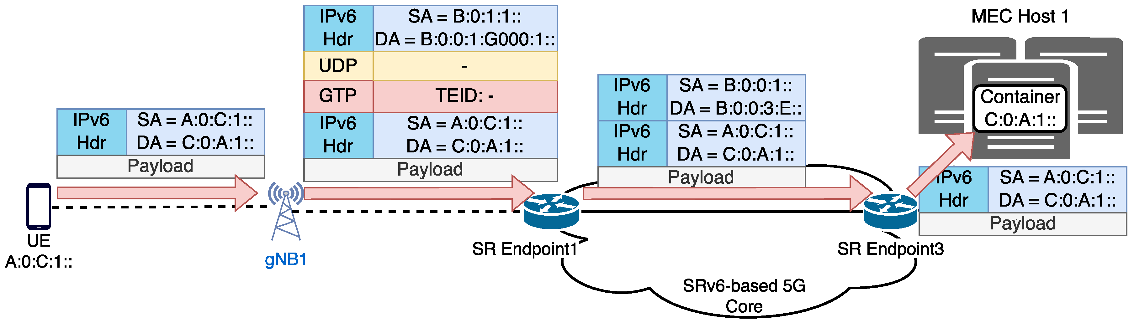
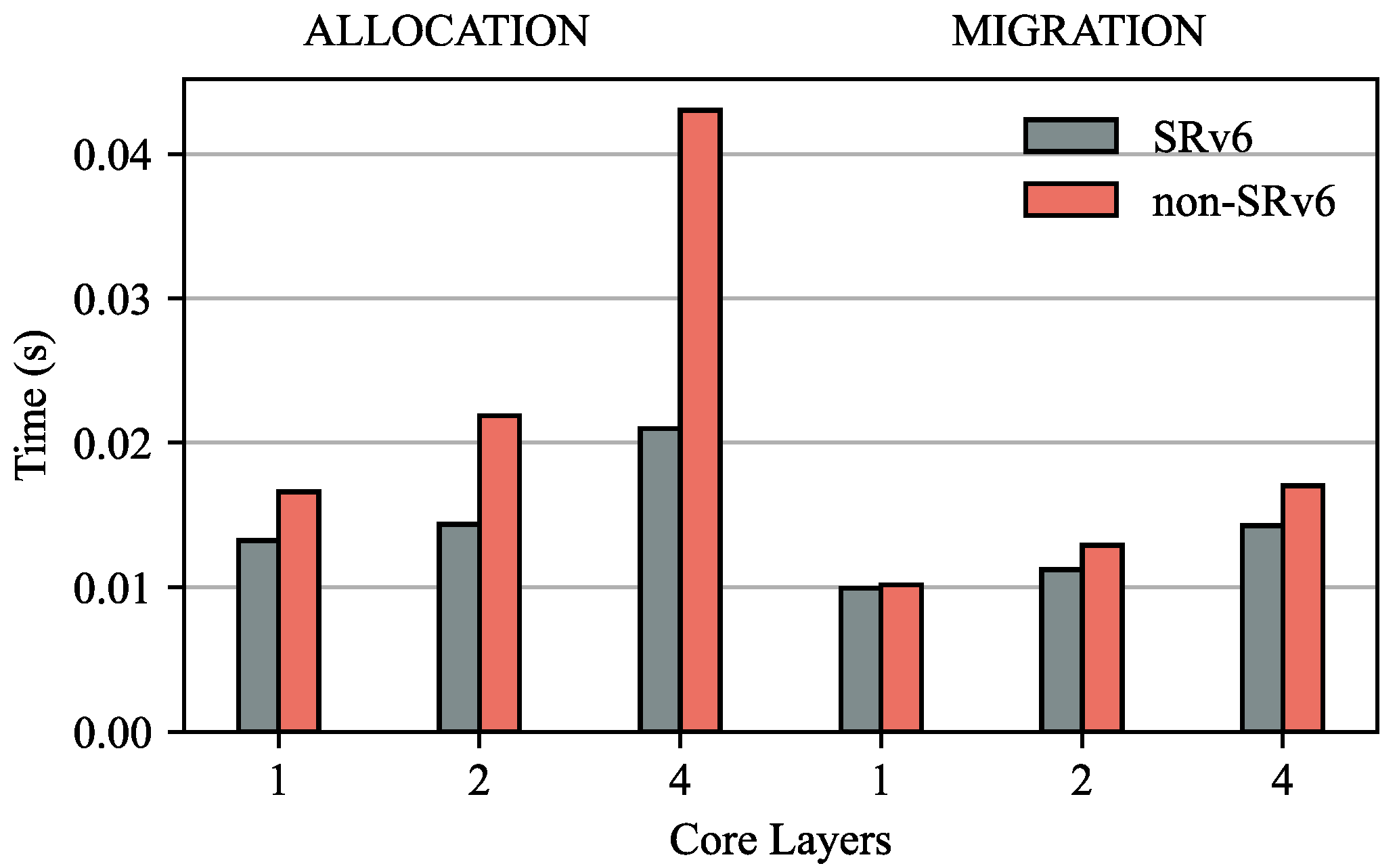
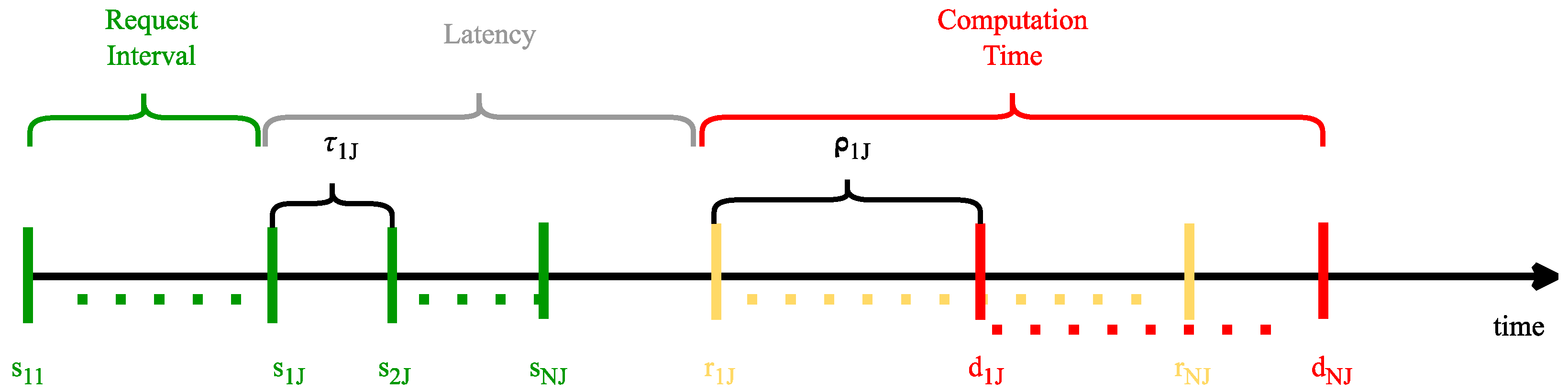
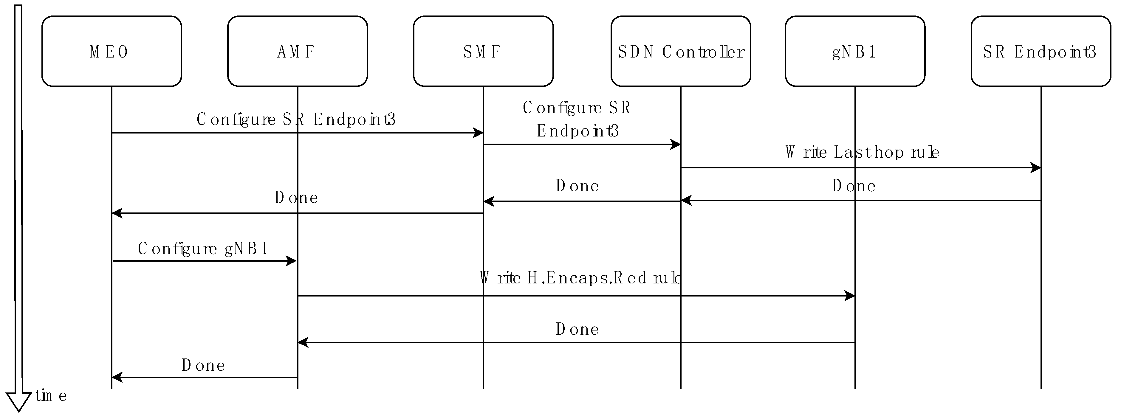
Table 1.
5G core devices addressing space.
| 5G Core Locator or Behavior | Allocated SID Prefix |
|---|---|
| Locator | B:0:0:<nodeid>::/64 |
| End behavior | B:0:0:<nodeid>:E::/80 |
| End.Buffer behavior | B:0:0:<nodeid>:B::/80 |
| End.M.GTP6.D BSID | B:0:0:<nodeid>:G000:<args>::/96 |
| End.M.GTP6.D.Buffer BSID | B:0:0:<nodeid>:GB00:<args>::/96 |
Disclaimer/Publisher’s Note: The statements, opinions and data contained in all publications are solely those of the individual author(s) and contributor(s) and not of MDPI and/or the editor(s). MDPI and/or the editor(s) disclaim responsibility for any injury to people or property resulting from any ideas, methods, instructions or products referred to in the content. |
© 2024 by the authors. Licensee MDPI, Basel, Switzerland. This article is an open access article distributed under the terms and conditions of the Creative Commons Attribution (CC BY) license (https://creativecommons.org/licenses/by/4.0/).
Share and Cite
MDPI and ACS Style
Lemmi, L.; Puliafito, C.; Virdis, A.; Mingozzi, E. SRv6-Based Edge Service Continuity in 5G Mobile Networks. Future Internet 2024, 16, 138. https://0-doi-org.brum.beds.ac.uk/10.3390/fi16040138
AMA Style
Lemmi L, Puliafito C, Virdis A, Mingozzi E. SRv6-Based Edge Service Continuity in 5G Mobile Networks. Future Internet. 2024; 16(4):138. https://0-doi-org.brum.beds.ac.uk/10.3390/fi16040138
Chicago/Turabian StyleLemmi, Laura, Carlo Puliafito, Antonio Virdis, and Enzo Mingozzi. 2024. "SRv6-Based Edge Service Continuity in 5G Mobile Networks" Future Internet 16, no. 4: 138. https://0-doi-org.brum.beds.ac.uk/10.3390/fi16040138
Note that from the first issue of 2016, this journal uses article numbers instead of page numbers. See further details here.