
Magnetic Gears and Magnetically Geared Machines with Reduced Rare-Earth Elements for Vehicle Applications

Department of Electrical and Computer, Engineering, Marquette University, Milwaukee, WI 53233, USA
*
Author to whom correspondence should be addressed.
World Electr. Veh. J. 2021, 12(2), 52; https://0-doi-org.brum.beds.ac.uk/10.3390/wevj12020052
Submission received: 4 March 2021
/
Revised: 17 March 2021
/
Accepted: 22 March 2021
/
Published: 24 March 2021
(This article belongs to the Special Issue Novel Permanent Magnet Machines and Drives for Electric Vehicles)
Abstract
:This paper covers a new emerging class of electrical machines, namely, Magnetic Gears (MGs) and Magnetically Geared Machines (MGMs). This particular kind of gears/machines is capable of either scaling up or down the revolutions-per-minute to meet various load profiles as in the case of mechanical gearboxes, but with physical isolation between the rotating components. This physical isolation between the rotational components leads to several advantages in favor of MGs and MGMs over mechanical gearboxes. Although MGs and MGMs can potentially provide a solution for some of the practical issues of mechanical gears, MGs and MGMs have two major challenges that researchers have been trying to address. Those challenges are the high usage of rare-earth Permanent Magnet (PM) materials and the relatively complex mechanical structure of MGs and MGMs, both of which are a consequence of the multi-airgap design. This paper presents designs that reduce the PM rare-earth content for Electric Vehicles (EVs). Additionally, the paper will ensure having practical designs that do not run the risk of permanent demagnetization. The paper will also discuss some new designs to simplify the mechanical structure.
1. Introduction
1.1. Main Introduction
The ability to scale torque/speed from one rotational component to the other is accomplished by gearboxes. This ability allows the power input torque/speed to meet the required load torque/speed by either scaling up or down the revolutions per minute. Coupling the gearbox high speed rotational component to electrical machines enables designing those machines for higher speeds/lower torques, and hence leads to significant reduction in size and cost. In addition, gearboxes are needed in some applications, for example, traction where driving a vehicle requires multi gear ratios to match multi load torque/speed profiles. Mechanical gearboxes have historically dominated a variety of applications such as renewable energy, aerospace, mining, oil and gas, and traction applications. This domination is traced back to the relatively high torque density of mechanical gearboxes. However, they suffer from mechanical teeth breakage, periodic maintenance, need for lubrication, noise, and vibration. To explain further, the torque transducing mechanism of mechanical gearboxes is based on the physical contact between shafts’ teeth, which poses significant challenges in terms of system reliability. A good example of this is a mechanical gearbox coupled to a wind generator. Wind speeds are continuously variable, causing sudden changes on the wind turbine speed; therefore, mechanical gearboxes are one of the most vulnerable components to fail due to their transferred torque mechanism. Due to this, a wind turbine’s typical lifetime is about 30 years, while the associated mechanical gearbox has an expected lifetime of only 5 years. As a consequence, this failure leads to inconvenient energy intermittences during the maintenance process [1], resulting in non-cost-effective systems. Moreover, mining, and oil and gas applications require gearboxes to meet the load profiles. Meanwhile, accessing the gearbox location for transmission oil change or regular maintenance is inevitably challenging. On the other hand, Magnetic Gears (MGs) had received slight attention before 2001 due to the complexity of the proposed topologies and poor torque density. In 2001 [2], K. Atallah and D. Howe at the University of Sheffield, UK, patented a surface mounted Permanent Magnet (PM) Coaxial MG (CMG) and described the flux modulation (FM) relationships that determines the gear ratio. FM-CMGs correspond to conventional planetary mechanical gearboxes. The patented CMG operates based on the FM concept using rare-earth PM material with a claimed torque density in excess of 100 kN·m/m3. This achievement attracted many researchers’ attention [3]. FM-CMG is a promising candidate to replace mechanical gears in some applications since they fundamentally function in the same way, but with the advantage of physical isolation between the shafts. The physical isolation between the shafts provides many advantages for FM-MGs over mechanical gears, described as follows: Lubrication free, no or reduced maintenance, higher reliability, reduced acoustic noise, no backlash, better overload protection, higher efficiency, and environmentally friendly technology.
1.2. Literature Review on Flux Modulation Magnetic Gears
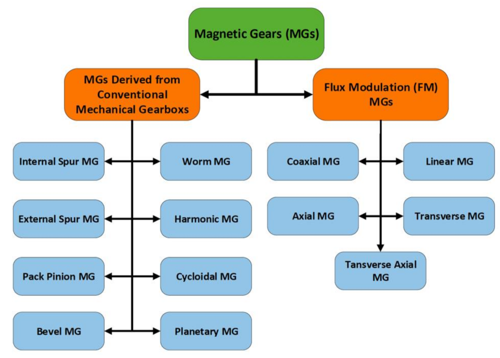
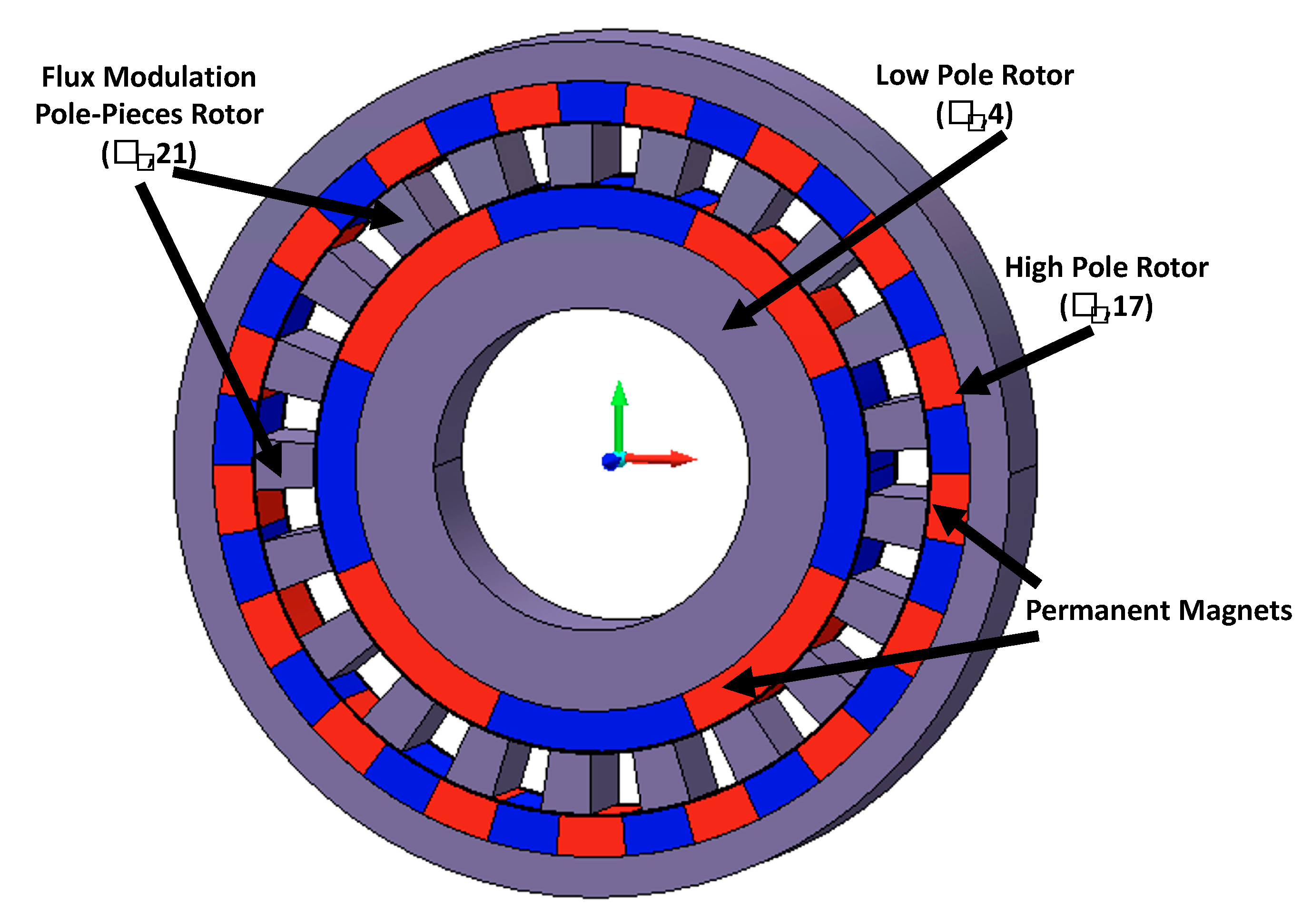
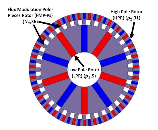
In order to introduce the reader to the MGs topologies, MGs can mainly be classified into two categories provided in Figure 1. The first category is the one that is mainly derived from mechanical gearboxes, which will not be considered in this paper due to its poor torque density [3,4,5,6]. On the other hand, the second category relies on the FM concept and will be considered extensively in this paper. FM-MG consists of three rotors: Inner rotor with (P1) pole-pairs, steel segments rotor in the middle with (Ns) pole-pairs, and outer rotor with (P2) pole-pairs as shown in Figure 2. The FM working principle is based on modulating the working Magnetomotive Force (MMF) periodicity (frequency) from the inner airgap to match the MMF frequency torque-transducing component in the other airgap by virtue of the steel segments or flux modulation pole-pieces (FMP-Ps) and vice versa. To further explain, any stable electromagnetic torque/force can be transmitted when two MMF sources with the same pole-pairs number (frequency) are interacting. In FM-MGs, the two MMF sources have different pole-pairs numbers. However, each MMF source frequency in FM-MGs is modulated by sandwiching the FMP-Ps between the rotor with higher number of poles (HPR) and the rotor with lower number of poles (LPR). As a result, this makes each MMF frequency (number of pole pairs) equal to the other MMF frequency in each airgap and allows for useful torque/force transmission. For the highest torque capability [2], the FMP-Ps number should be the sum of HPR and LPR pole-pairs as provided in Equation (1).
P1 + P2 = Ns
In [2], the FM concept is illustrated by showing how the first MMF source can be modulated to match the other MMF source which satisfies equation (1). Therefore, the gearing effect is created in each airgap to enable a useful torque transmission. The FM-MG can have a fixed single gear ratio if two rotors are rotating simultaneously, whereas continuously variable transmission (CVT) is obtained when all three rotors are rotating together [7]. Since the reveal of [2], a flurry of activity has taken place to apply these basic principles, provide a theoretical understanding, and improve the designs such that now, MG performance is considered to be on par with that of mechanical gears [3]. All of which of course was facilitated by the invention of rare-earth magnets in the 1980s. Table 1 summarizes various FM-MGs’ torque densities, gear ratios, and types of configuration, along with the corresponding references.
1.3. Literature Review on Magnetically Geared Machines
Evolution of FM-MGs and high energy product PM material have contributed to integrating such a high torque density/passive device like FM-MGs into the context of electrical machines. As a result, high torque density electrical machines have been emerging and generally labelled under Magnetically Geared Machines (MGMs). These emerging machines revived the ongoing research on electrical machines as well as providing degrees of freedom to various industry applications. To clarify, MGMs can have multi mechanical/electrical ports for power split devices as well as CVT operation to meet various operating conditions [30]. Conversely, conventional electrical machines are only limited to one mechanical and one electrical port. These diverse advantages are attractive with the requirements of wind power generation, marine, aerospace, and traction applications. Thus, enabling such a contactless technology integrated with electrical machines in such applications, resulting in reliable promising candidates and compact systems, can be a key enabler towards fully electrified systems.
As for identifying the technical differences between conventional and magnetically geared machines, it is known that the electromagnetic torque in conventional machines is proportional to the electric and magnetic loadings, as shown in expression (2).
where (Telectromagnetic) is electromagnetic torque in (Nm), (Bg) is the magnetic loading or the airgap flux density in (Tesla), and (A) is the machine electric loading in (AT/m).
Telectromagnetic ∝ Bg × A
However, in MGMs, the gearing effect plays a significant role in terms of boosting the electromagnetic torque. To clarify, the MMF angular velocity in the inner airgap (the LPR side) of any FM-MG is modulated from a high speed/low pole-pairs number to a low speed/high pole-pairs number, while both frequency and power are the same. This makes the HPR rotate with low angular velocity, and since the power is equal on input and output shafts, the torque is scaled up by the gear ratio. Therefore, MGMs follow a different expression (3).
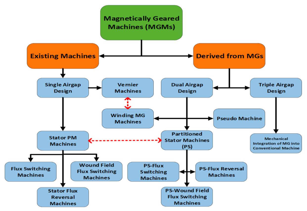
where (Gr) is the gear ratio. MGMs family includes diverse categories based on the classification criterion. In this paper, MGMs will be categorized based on the number of airgaps, making it easier to identify each category. The schematic diagram shown in Figure 3 categorizes MGMs into three categories and highlights the main variations. The red dashed lines indicate that there is a correlation between the two types. For example, for certain slot/pole combinations in winding MG machines, the airgap between the FMP-Ps and stator windings can be eliminated, resulting in Vernier Machines.
Telectromagnetic ∝ Bg × A × Gr
Due to the diversity of MGMs topologies and limited space, the focus in this paper will be on Partitioned Stator-Flux Switching (PS-FS) MGM with dual airgaps. Meanwhile, Table 2 lists references from literature as an example on other categories.
1.4. Challenges of Magntic Gears and Magnetically Geard Machines
Although FM-MGs and MGMs can potentially provide a solution for some of the practical issues of mechanical gears, FM-MGs and MGMs have their own challenges that researchers are trying to address. The main challenges that impact performance are summarized as follows: Segmented structure and many small pieces to assemble, low torque density, complexity in structures, high usage of rare-earth material, relatively low gear ratio, high operating frequency, as well as weak and impractical mechanical structures.
Those lead to relatively limited tip speed (The tip speed is the linear speed of the outer surface of a rotor; it is the limiting factor in terms of mechanical stresses) on LPR or weak mechanical structures (due to the segmented structure), low torque density (due the high flux leakage or eliminating PM material), complexity in structure making the prototypes difficult to assemble (to boost the torque density), the significant use of rare-earth PMs (due to the large effective airgap), relatively low gear ratio (practical aspect related to PM materials), reduced efficiency (due to losses at higher frequencies), as well as mechanical issues (due to the multi mechanical ports/bearings). It should be noted that it is often the case that one particular issue can be “resolved”, but at the expense of making another issue appear or get much worse. For example, [14] demonstrates a FM-MG prototype with the highest torque density reported in literature so far [4,5,6]. However, the rotor tip speed is limited by the segmented structure beside the low gear ratio 1:4.25. In [12], although a HSR with interior PMs and FMP-Ps with two supportive bridges were adopted to improve their mechanical strength; the torque density was significantly reduced. Moreover, the highest gear ratio for FM-CMG was 1:75 with modest torque density (37.1 kN·m/m3) [6,18].
1.5. Motivation of This Study
There have been continuous significant efforts to enable high torque density/low-cost electric drive systems in a variety of applications which include electric machines and power electronics. One strategy is to reduce the machine rare-earth content while attempting to maintain a comparable performance. Since there has been a growing interest to minimize or eliminate the rare-earth PM content in electric machines [53,55,56,57] and due to the multi airgap design of FM-MGs and MGMs, a large volume of PMs is typically required to achieve a reasonable torque density. Rare-earth magnets are generally expensive, but some grades are more so than others. In particular for application with high temperature operation, such as traction, alloying is needed to reduce demagnetization risk. This is achieved by adding some so-called heavy rare earth materials, such as dysprosium (Dy). Unfortunately, although the proportion of Dy needed is small, its cost is particularly high. Therefore, some work is ongoing to develop designs that do not need Dy addition to the rare-earth magnet, but achieve high temperature operation nonetheless (so-called Dy-free magnets). Two kinds of Dy-free NdFeB are commercially available and have been studied thoroughly in [56,58]. The first one is with high remanence and knee point in the second quadrant, which presents a significant challenge due to the armature reaction effect at high temperatures. The second type is the one with low remanence and knee point in the third quadrant, allowing the machine to operate with high coercivity, but the machine power density may drop. Moreover, ferrite PM has a relatively low energy product and is subject to demagnetization at lower temperature.
1.6. Objective and Organization of This Paper
As a consequence, this paper aims to address foregoing PM material challenges and investigate the electromagnetic performance of blended magnet designs proposed for electric vehicles (ferrite with both Dy-NdFeB and Dy-free NdFeB) in the context of FM-MGs and MGMs as to extend the work in [59,60].
Beside the main target, issues of FM-MGs and MGMs will be taken into account to reach a compromise while retaining a competitive electromagnetic performance. These includes practical designs, tolerance of demagnetization, simple mechanical structure or conventional topologies, and sustainability cost reduction in the proposed topologies. Additionally, this paper will use a 2D-Finite Element Analysis (FEA) MagNet and OptiNet Mentor Graphics software to minimize the computational time associated with the 3D analysis. 3D effects are not expected to have a significant impact.
This paper is arranged as follows; the first section covers detailed introduction. The second section covers the analysis results of CVT FM-CMG proposed for Electric Vehicles (EVs). The third section presents the analysis results of a PS-Flux Switching Machine (FSM) to meet the U.S. Department of Energy FreedomCar 2020 specifications for EVs, followed by conclusions and future work.
2. High Torque Density Low-Cost Flux Modulation-Coaxial Magnetic Gear
2.1. Intorduction and Application
Gearboxes with multi or single gear ratios are needed in EVs and hybrid EVs (HEVs) to meet the targeted torque/speed profiles. To clarify, Nissan Leaf 2010 is an EV and uses a single ratio mechanical gearbox to meet its wheels’ rated speed [61]. In addition, Toyota Prius (HEV) uses a planetary mechanical gearbox to achieve the CVT functionality between the two electrical machine and mechanical combustion engine [62]. On the other hand, FM-CMG can fundamentally achieve the exact functionality of their mechanical counterparts whether to operate with a single ratio or with CVT characteristics. Therefore, this section will consider designing and analyzing a FM-CMG for HEVs and EVs. Moreover, this paper will consider only the operation with a single gear ratio, while the CVT operation will be the focus of a future paper.
2.2. Baseline Design, Materials, and Specifications
In FM-CMG, PMs are the only source of excitation as presented in Figure 2; however, airgap magnetic loading varies based on the rotor design and/or effective PM utilization. This means different PMs configurations would significantly change the peak airgap flux density (Bg), which emphasizes the importance of selecting the rotor topology or inventing new topologies. A comparative study between various rotor designs was introduced in [63,64], which draws a conclusion indicating that spoke PM designs have the highest torque density among other designs at the same PM quantity. This is mainly due to the flux concentration effect (two PM poles pushing flux in the same direction) through the steel segments between circumferentially magnetized PMs as shown in Figure 4. Moreover, experimental validation results presented in literature demonstrate a spoke PM FM-MG prototype with the highest torque density among other rotor designs [4,5,6,14]. Consequently, both LPR and HPR are configured with a spoke PM design.
Various commercially available PM types are considered in this paper: Dy-NdFeB, Dy-free NdFeB, and ferrite are listed in Table 3 with their magnet properties at 20 and 80 °C. The Dy-free NdFeB has slightly higher energy production in comparison to Dy-NdFeB. The proposed FM-CMG can be potentially designed to have a high-tip-speed in which a relatively high-yield-strength material is required for reliable operation with variable loads and physical environments. HF-10 from AK Steel (with yield strength of 450 MPa) is adopted in the design. Material specifications are listed in Table 3, while Table 4 shows the assumptions of the active material market prices. It should be noted that material prices are influenced by the market supply/demand as well as quantities of purchase.
The baseline design of the proposed FM-CMG uses a Dy-NdFeB (with heavy rare-earth elements), and its specifications as well as other design parameters are provided in Table 5. It is seen that the proposed FM-CMG is targeting high speed operation on the LPR, while the low-speed rotor is the FMP-Ps with a speed of (1388.88 rpm) corresponding to a gear ratio of 1:7.2. The gear ratio in this case is the count of the FMP-Ps over the LPR pole-pairs count. It should be noted that the considered design is operating with a single gear ratio (HPR is fixed); however, the proposed FM-CMG can accomplish the CVT functionality when all the rotors are rotating simultaneously. CVT will be considered in a future paper.
2.3. Design Configuration
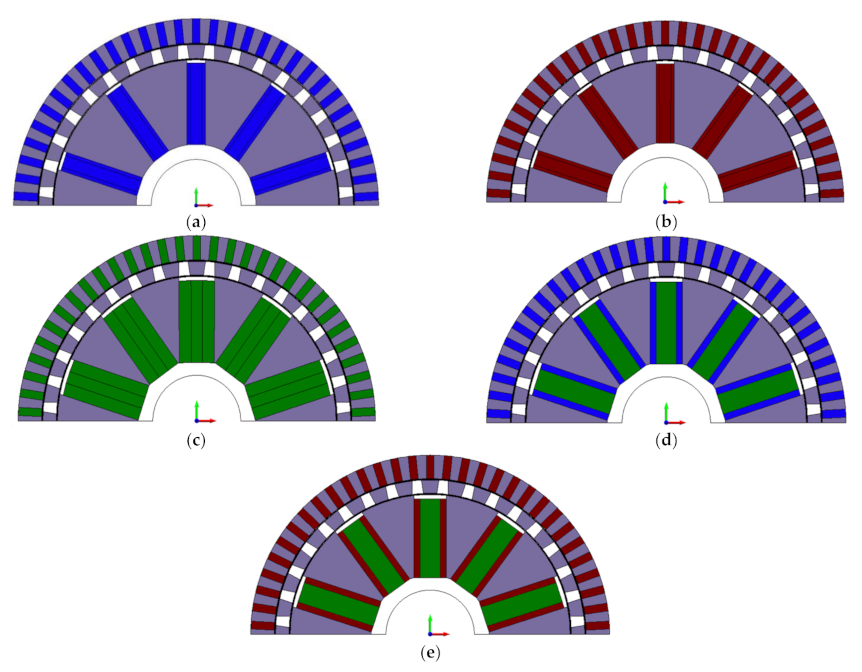
The baseline design has been established in the previous subsection with Dy-NdFeB; therefore, the task of this section is to introduce various designs by using other magnet types/grades. First, three designs are considered using only one PM type in each design. The first design is inherited from the baseline design and uses Dy-NdFeB, the second design utilizes Dy-free NdFeB, and the third design has only ferrite PM. The FEA solid models are shown in Figure 5. The purpose of introducing the three designs using only one PM type is to examine the torque capability when using each type separately and to provide a fair comparison to the hybrid magnet designs. All the design parameters are kept fixed, except the LPR PM width was changed to achieve the highest possible torque capability relative to the baseline design.
Additionally, two designs are considered with blended magnets. The fourth design uses a blend of Dy-NdFeB with ferrite PM, while the fifth design has a blend of Dy-free NdFeB and ferrite PM. The blending of two PM types will only be done on the LPR since there is enough space to adopt ferrite PM compared to the HPR, which has to be oversized if ferrite is adopted. The rectangular LPR PM in the first three designs is replaced with three rectangular PM layers configured in series (that is, the magnets are stacked in the direction of magnetization, or the north pole of one segment abuts the south pole of another) as provided in Figure 5. The ferrite layer is sandwiched between two NdFeB layers. The series configuration enables uniform flux to cross the three layers of PMs, which results in better utilization of the ferrite magnet. The hybrid magnet FEA models were fully parameterized to examine the impact of the NdFeB and ferrite PM widths on torque production.
2.4. Torque Capabilities Repersenation
All the design parameters were fixed except the PM width. The hybrid magnet topologies show a gross reduction of the rare-earth PM content of around 17.5%, and a rare-earth PM reduction of ~31.5% in the LPR of the fourth and fifth designs compared to the first and second designs. Moreover, the reduction in the steel content is advantageous in case of applications that require high yield strength materials which are typically more expensive compared to regular steel.
This significant reduction of rare-earth materials led to a marginal reduction in the torque as shown in Table 6. Torques on various components and gear ratios of the various deigns are summarized in Table 6. It can be seen from Table 6 that the torque densities in the hybrid designs are lower by ~4.5% compared to their counterparts. On the hand, the specific torques have been increased in the hybrid designs due to the low volumetric mass density of ferrite. Clearly, the ferrite contribution to the torque capability in the hybrid designs is improved compared to the Ferrite PM Design that uses only ferrite.
2.5. Impact of Rotors Retention
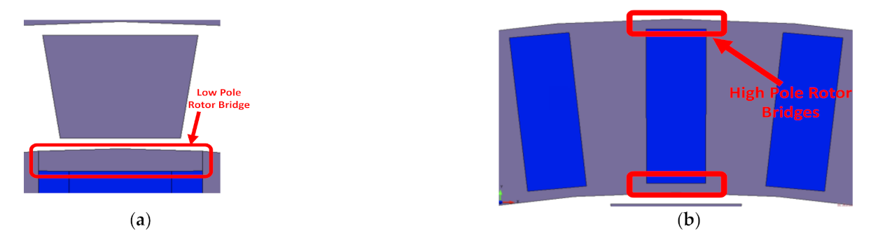
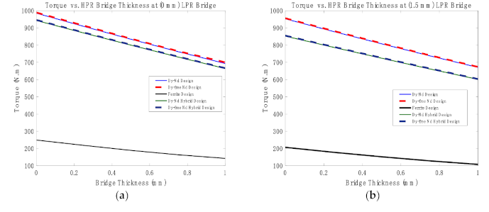
The robustness of the mechanical structure is critical, especially at high tip speeds operation. As a consequence, particular attention should be paid to enhance the design structure and ensure higher reliability. In the case of spoke FM-MG, magnetic bridges should be added in the HPR and LPR to retain the PMs against the impact of the centrifugal force as shown in Figure 6. Bridges in the HPR are added to the inner and outer surfaces, whereas the LPR has only bridges at the outer surface. The drawback of these bridges is a significant reduction in the torque capability as the bridge thickness increases due to the shunted magnet flux in those areas. Consequently, sensitivity analysis is performed on HPR as the bridge thickness is increased from 0 to 1 mm in steps of 0.25 mm to both surfaces as shown in Figure 7a, whereas the LPR does not have any bridge. It is shown that the torque is significantly decreased by about ~30% as the bridge thicknesses increased in all the designs that have Dy-NdFeB or Dy-free NdFeB in the HPR. Figure 7b represents the same cases, but when the LPR is retained with a bridge of 1.5 mm. It can be shown that the hybrid designs are more sensitive to the LPR bridge. To explain further, the LPR bridge can be highly saturated with pure NdFeB designs. Conversely, hybrid designs that have ferrite do not saturate the bridge effectively as in the case of the first two designs, which negatively leads to further torque reduction. For the analysis moving onwards, a bridge of 0.5 mm is added to the HPR both surfaces, while the LPR is set with a bridge thickness of 1.5 mm. Detailed mechanical analysis is still required prior to the final design step.
2.6. Evaluation of PM Demagnetization
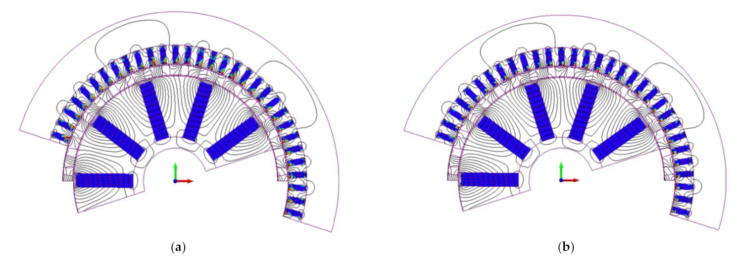
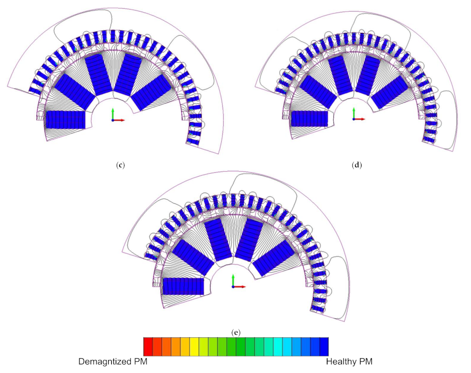
Magnets is prone to demagnetization in FM-MGs due to the impact of temperatures, as in any PM machine. The risk of demagnetization was evaluated at the rated temperature (80 °C) for five electrical cycles by using 2D-FEA tool software to highlight the demagnetized regions over time. The simulation period should be enough to capture demagnetization. Figure 8 shows the demagnetization results for the considered designs. The demagnetization indication is when the scale approaches the red region in Figure 8, whereas healthy PM can be represented by the blue regions. Dy-NdFeB Design suffers from partial demagnetization in the HPR PM poles as shown in Figure 8a. Similarly, Dy-free NdFeB Design faces the same challenge as shown in Figure 8b. This is traced back to the large demagnetization force applied on the HPR small PMs from the LPR side. To mitigate such issues, the LPR PM width can be minimized to reduce the demagnetization force applied on the HPR PMs.
Interestingly, hybrid designs may be less prone to this challenge. Only few locations are close to partial demagnetization, which is due to the lower demagnetization force and flux density produced by the two PM types blended together. Ferrite Design presents a similar case to the hybrid designs. Torque can be significantly reduced because of the severe demagnetization in the first two designs. However, the used FEA software does not calculate the torque reduction and assumes healthy PMs unless recoil curves and data of all the PM types are defined.
Therefore, the aforementioned results for the first two designs do not show any reduction of the torque capability, which is optimistic. It is emphasized that the gear ratio selection is tied to demagnetization at elevated temperatures due to the large number and small size of PM poles that are easier to demagnetize. Moreover, this tradeoff with high gear ratios requires iterative gear ratio selection in parallel with the rated operating temperature. At this preliminary stage of the investigation, we can conclude that demagnetization needs to be integrated in the optimization process.
2.7. Efficiency and Cost Analysis
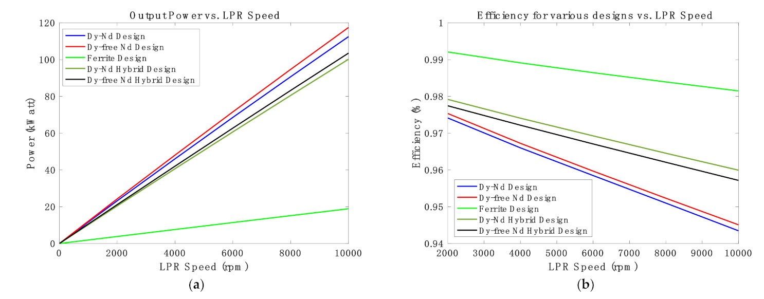
Losses in FM-MGs are broken down into three components explained as follows: Iron losses (lamination Hysteresis and eddy current losses), PM eddy current losses, and mechanical losses (Windage, friction, bearing, and assembly defects losses). The first two losses can be predicted using 2D-FEA software (The PM is assumed to be segmented in the circumferential and radial directions); however, the mechanical losses are ignored in this analysis. Due to limitations in space, only the final design results are shown. Various design efficiencies and mechanical power outputs are shown in Figure 9. The mechanical output power in Figure 9a is the mechanical power of LPR corresponding to the considered speed ranges. Moreover, the LPR torques for each design are multiplied by the angular velocities of each speed, and eventually result in Figure 9a. Since the torque value is almost fixed except to account for losses, the output power ends up increasing linearly with speed. It is shown that all the designs achieve high efficiency in excess of 94% at the top speed. It is also seen that the hybrid designs transfer comparable mechanical power output to designs that have NdFeB-only. Designs that have Dy-free NdFeB transfer higher torques than designs that have Dy-NdFeB. This is because the Dy-free NdFeB remanence and coercivity are higher at the operating temperature. It should be noted that the analysis in this section is performed at a temperature of 80 °C, assuming the highest and rated temperature for the proposed designs will not exceed it.
It was shown in the foregoing analysis that the hybrid designs are highly competitive compared to NdFeB-only configurations. The hybrid designs exhibit a much reduced risk of demagnetization, high efficiency, reduced rare-earth content, reduced steel content, and comparable torque densities. Results presented in Table 7 are obtained at 80 °C, and do not take into account the reduction of the torque capability due to demagnetization in the first two designs as previously discussed. This indicates that the torque can be significantly reduced in pure NdFeB designs. Moreover, the active material cost is calculated based on the active material price assumptions in Table 4, as well as the active material masses for the gear parts in Table 6. Hybrid designs demonstrate encouraging reduction in active material cost by about ~13% and sustainable elimination of rare-earth materials. In order to check the utilization efficiency of the NdFeB, the torque capability of each design is divided by the NdFeB mass. It is shown in Table 7 that hybrid designs have higher utilization efficiency of NdFeB. It is concluded that the hybrid designs have several advantages over their counterparts.
3. Partitioned-Stator Permanent Magnet Flux Switching Machines with Reduced Rare-Earth Content
3.1. Introduction and Specifications
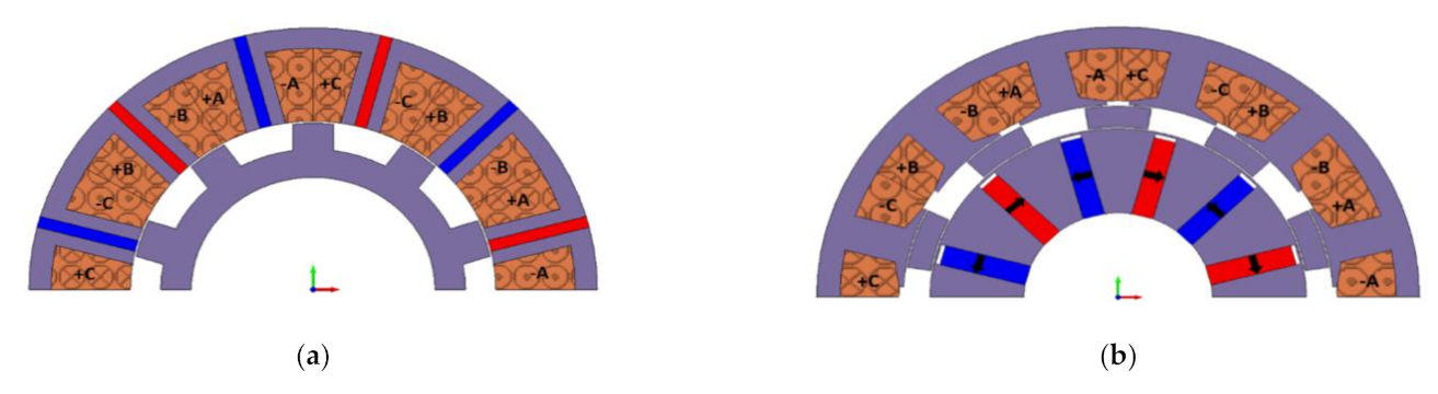
PS machines are newly developed machines based on the dual-airgap MGMs and stator PM machines. These machines have one rotor sandwiched between two separate stators. The outer stator is equipped with windings as a LPR, while the inner stator has the PM poles or wound field excitation as a HPR. The rotor (FMP-Ps) in this case is sandwiched between the two stators. This is unlike the stator PM machines, which have both the PM poles and windings sharing the same stator. Reference [30] shows stator PM machines, including the three main topologies: PM Flux Switching Machines, Flux Reversal Machines, and Wound Field Flux Switching Machines, as well as their counterparts with the separated stators (PS Machines). Since the focus in this paper is on FSM, Figure 10 demonstrates a conventional PM FSM with its counterpart PM PS-FSM. It is obvious that stator PM machines have a space constraint in the stator, which limits the boosting of magnetic and electric loadings. Since the rotor space is not fully utilized, PM poles or the wound field excitation can be moved to the inner space to create an inner stator. As a result, PS machines enable boosting magnetic and electric loadings with an improved efficiency and higher torque density per copper losses [30]. Diverse configurations of the inner stator in PS machines are realized in [39], such as ‘V’ shape interior PM, whereas the outer stator can be equipped with either distributed windings or fractional slot concentrated windings (FSCW) [40]. The PS machines principle of operation and investigation of their performance was presented in [41]. PS-FSMs have the highest torque density among other PS machines with potential operation with constant power over the entire speed range [41]. These advantages can be a key enabler to a new era of traction application motors where high torque density machines as well as excellent Flux Weakening (FW) capability are needed. Therefore, the focus in this section will be on PS-FSM.
Despite the advantages that PS-FSMs offer, there are other challenges that have to be considered. One of these challenges is the high PM quantities utilized to develop high torque per unit volume machines. However, the current trend in advanced electrical machines is to reduce the rare-earth content while maintaining competitive electromagnetic performance. Therefore, this section will present novel configurations with blended PM types (ferrite with either Dy-NdFeB or Dy-free NdFeB) that can be suitable for traction application. The proposed designs will try to meet the U.S. Department of Energy specification of the FreedomCar 2020.
3.2. Materials
In order to enable electrified systems in the transportation sector, high power density electrical machines with low cost are needed. One impactful methodology is to reduce the content of heavy rare-earth PM materials. While high power density machines are equipped with high energy product rare-earth PM elements (Dy-NdFeB), their price volatilities are a major concern. The Dy element is a heavy rare-earth element and the rarest and most expensive element in the Dy-NdFeB PMs. It is the key enabler to achieve high coercivity at elevated temperatures. However, Dy-free NdFeB PMs can be utilized as an alternative option. Dy-free NdFeB can be categorized into two types as follows: (1) High remanence and lower coercivity (sintered) and (2) low remanence and higher coercivity (hot-pressed). The first type runs the risk of demagnetization, especially under full load and elevated temperatures. On the other hand, the high remanence enables high power-density. This trend is reversed with the second type, where the demagnetization risk is lower, but the lower remanence can penalize the power density. Therefore, the second type will be used to reduce the demagnetization risk at rated temperature (at 140 °C) and full load. Ferrite PM is a second candidate to provide sustainable cost reduction; however, ferrite runs the risk of demagnetization at low temperatures (at −40 °C). The ferrite PM used in the coming analysis has relatively high coercivity (Hc), which helps minimize the risk of demagnetization. Therefore, the foregoing challenges with PM materials can be mitigated by blending ferrite PM with either Dy-NdFeB or Dy-free NdFeB to help significantly reduce the cost. Four designs using three different commercially available PM materials are considered: (i) Dy-NdFeB Design, (ii) Dy-free NdFeB Design, (iii) Dy-NdFeB and Ferrite Design, and (iv) Dy-free NdFeB and Ferrite Design.
The target is to introduce a PS-FSMs with reduced rare-earth content by blending ferrite with both Dy-NdFeB and Dy-free NdFeB with comparable performance to the first two designs. PM properties are given in Table 9 at the rated temperature (140 °C). In terms of the electrical steel (M-19 29 Gauge) with a lamination thickness of 0.35 mm is used for the four designs. The assumed materials prices are summarized in Table 10.
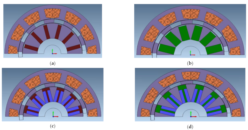
3.3. Considered Designs
This subsection introduces four designs. The baseline design uses Dy-NdFeB and is shown in Figure 12a. The second design shown in Figure 12b was developed by using Dy-free NdFeB and attempted to have the same torque capability as the baseline design. Additionally, a newly developed PM shape is introduced to sustain comparative electromagnetic performances to the non-blended magnet designs. The merit of using the (T-shape) is discussed in [60]. The third design is demonstrated in Figure 12c with ferrite and Dy-NdFeB, while the fourth design has a blend of ferrite and Dy-free NdFeB as shown in Figure 12d. The ferrite is shown in a light blue color, while the (T-shape) is the NdFeB PM content. The main parameter changes in the three deigns compared to the baseline design (Dy-NdFeB Design) are the PM mass and the machine axial stack length. The proposed designs were all optimized at the rated temperature (140 °C) to have similar characteristic currents (short-circuit current), equal PM flux linkage values, and resistance against demagnetization at (140 and −40 °C) through a parametric model. The key criterion of the optimization is to make the characteristic current equal to the rated current. The significance of this condition is to enable driving the machine with constant power over the entire speed range during the FW operation, which is typical in the case of traction application motors. The optimization condition is given in Equations (4) and (5).
where (ISC, λPM, and Ld) is the short circuit current, PM flux linkage and the direct-axis inductance, respectively. Generally speaking, this is accomplished by varying either the PM width within the available space or the outer radius of the inner stator (PM stator). It is preferred to increase the PM width unless there is a space limitation as shown in the blended Dy-free NdFeB with Ferrite Design. In this case, the outer radius of the inner stator has to grow radially to maintain the stated condition. It should be noted that the characteristic current is independent of the machine stack length; as a result, the goal of increasing the stack length is to result in similar back EMF waveforms and thereby torque and power as shown in the Dy-free NdFeB and Dy-NdFeB with Ferrite designs. Table 11 lists all the four designs geometrical parameters, while Table 12 provides the identical parameters among the four designs.
ISC = λPM/Ld
ISC = Irated
The reduction of the rare-earth content in Dy-NdFeB with Ferrite design compared to Dy-NdFeB is about ~12.5%, while Dy-free NdFeB with Ferrite design reduces rare-earth content by ~44% compared to Dy-NdFeB. The use of the second type of Dy-free with low remanence and high coercivity requires more space to improve the magnetic loading in the Dy-free NdFeB and Dy-free NdFeB with Ferrite designs. However, it should be noted that these two designs successfully avoided the demagnetization risk, as will be discussed later, which is inevitably challenging for the first Dy-free type with high remanence and low coercivity. In addition, all the designs have successfully met the torque requirements, as will be shown in the next subsection.
3.4. Electromagnetic Performance
In this subsection, the electromagnetic performance of the hybrid designs (Dy-NdFeB with Ferrite Design and Dy-free NdFeB with Ferrite Design) is compared with that of their counterparts (Dy-NdFeB Design and Dy-free NdFeB Design). The results are obtained using 2D-FEA software at 140 °C. Rated and peak torque waveforms, and torque-power/speed plots for the various designs will be presented.
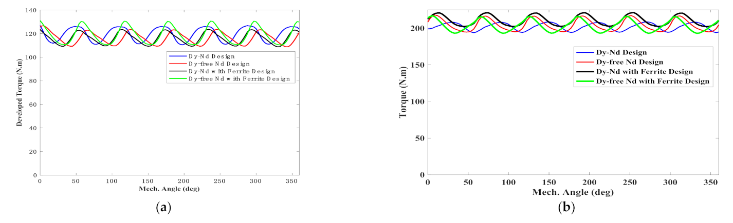
All four designs were simulated at (2800 rpm–200 Arms) to achieve the maximum torque per ampere. The developed electromagnetic torque for the considered designs is shown in Figure 13a. All the designs have similar average torque at the base speed and rated current. Moreover, the feasibility of blending diverse magnet types in the hybrid designs in terms of the torque capability is demonstrated.
The torque ripple in the considered configuration 12 slots/10 pole-pairs is significant due to the low least common multiple between the PM poles and FMP-Ps number. However, by implementing various torque-ripple reduction techniques, the torque ripple can be minimized.
Based on the specification listed in Table 8, the four designs have to achieve the peak power condition (55 kW for 18 s) at the base speed and peak rms phase current (2800 rpm–400 Arms). In order to accomplish this condition, the current density has to be feasible from a thermal point of view to avoid overheating the windings. Therefore, this condition was achieved for all the designs with manageable current density of (9 Arms/mm2), which indicates that all designs potentially can produce more power, assuming the PMs will not demagnetize (see next subsection). Figure 13b demonstrates the peak torque condition for the four designs. All designs produce an approximate average torque of ~200 N·m at the base speed (2800 rpm), which corresponds to ~58 kW. It is shown that Dy-NdFeB with Ferrite Design has slightly higher torque in comparison to Dy-NdFeB Design. On the other hand, the Dy-free NdFeB with Ferrite Design has similar torque capability to its counterpart.
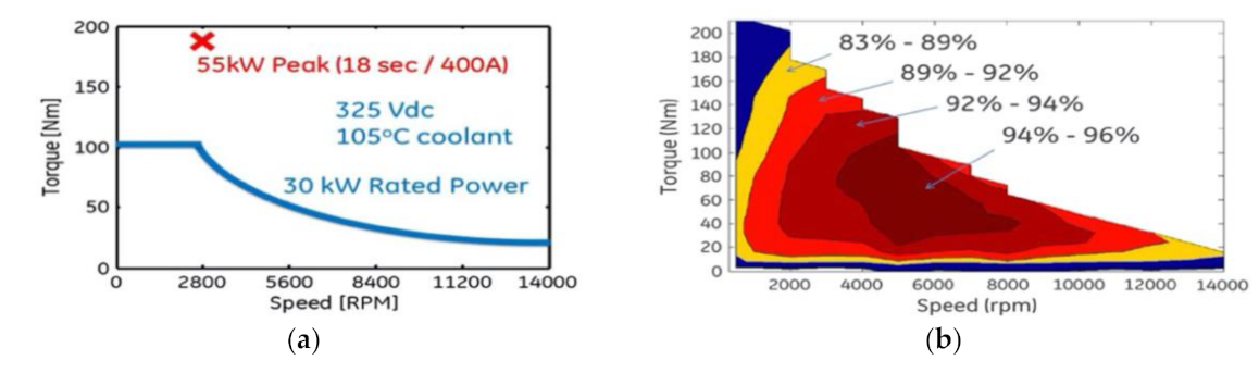
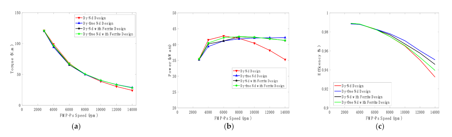
Part of the specification listed in Table 8 and shown in Figure 11 is to deliver a continuous output power of 30 kW from the base speed (2800 rpm) up to the maximum speed (14,000 rpm). In order to accomplish this condition, the machine should be optimized to have an optimal FW operation by fulfilling the condition in Equation (4), as explained in [65]. All the designs have been optimized to satisfy that condition and have a characteristic current near 200 Arms. The torque/power-speed curves for the considered designs are provided in Figure 14.
It can be seen from Figure 14a that the Dy-NdFeB design has lower torque capability compared to the other designs beyond 10,000 rpm. On the other hand, the other designs show similar torque capabilities.
In terms of the delivered mechanical power, all designs were able to meet the condition of continuous operation of 30 kW over the entire speed range as shown in Figure 14b. Dy-NdFeB Design demonstrates difficulties to maintain a constant power over the whole speed range. It is indicative that the design needs higher reactive current than other designs to negate the PM flux linkage. On the other hand, the other designs are able to deliver a continuous power of more than 40 kW over the entire speed range. In addition, all designs are able to operate with an efficiency in excess of 93% across the entire speed range taking into account (PM eddy current losses, iron losses, and winding (AC and DC) losses).
3.5. Demagnetization Analysis
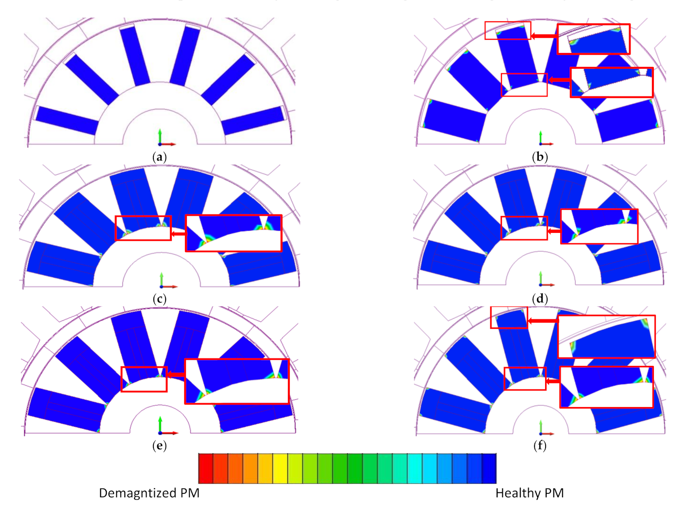
Magnets are prone to demagnetization under the impact of both temperature and stator current especially under FW operation. Consequently, designers of PM machines should be cautious during the design stage to avoid the PM risk of demagnetization. The three types of PMs used in this analysis have a knee point in the third quadrant, which is advantageous to reduce this risk. In order to analyze the PM demagnetization, 2D-FEA software is used, which can highlight the demagnetized regions in the PM. The used simulation condition was applying twice the rated current (400 Arms) along the negative d-axis at the 140 °C for two electrical cycles. In the designs that have ferrite, it is important to additionally evaluate the demagnetization at −40 °C since ferrite PM is prone to demagnetize at lower temperatures due to the positive coercivity thermal coefficient. The chosen condition represents the worst-case scenarios representing the transient current under symmetrical three-phase short circuit. In Figure 15, it is demonstrated that the PM is healthy when the scale is in the blue color, while the red color represents demagnetized PMs. It is shown that Dy-NdFeB Design has no signs of demagnetization. On the other hand, the other three designs show partial demagnetized regions at the inner and outer inner stator radius, which is typical in this case. It is concluded that the proposed design can operate safely under the required specifications. Additionally, the merit of using a T-shape is realized by showing no demagnetization signs in the hybrid designs [60].
3.6. Cost Analysis
The previous analysis demonstrated encouraging results in terms of the electromagnetic performance. This section investigates the impact of the hybrid magnet approach on the power and torque densities. Additionally, it will be shown that the cost was reduced which is critical from a mass production perspective. The torque density was calculated at the base speed (torque at rated current over machine active volume), whereas the power density is calculated at maximum speed (power at rated current over machine active volume). The cost was calculated for each design based on the price assumptions presented in Table 10 and active material masses given in Table 11.
Based on the results presented in Table 13, it is shown that all the Dy-NdFeB Design demonstrates higher torque density than the other designs. However, the other designs show lower torque density with lower cost. In terms of the power density, although Dy-NdFeB Design has a limited speed range, the power density is still comparable to the other designs. The cost in Dy-NdFeB with Ferrite design was reduced in comparison to Dy-NdFeB with Design by ~5%, whereas Dy-free NdFeB with Ferrite design shows a reduction of 18%. In conclusion, there is always a trade-off between cost and torque/power density. Additionally, the concept of hybrid magnet leads to interesting results, including reduction of rare-earth content in the context of MGMs.
4. Discussion and Overview
In this paper, a summarized survey of newly emerging electrical machines, namely, Flux Modulation-Magnetic Gears (FM-MGs) and Magnetically Geared Machines (MGMs), is presented. The goal is to identify the main challenges and propose some potential solutions to address them for HEVs and EVs. The high rare-earth PM content is one of the key challenges. As a consequence, FM-MGs and MGMs with reduced rare-earth content were proposed (combining ferrite with either Dy-NdFeB or Dy-free NdFeB). The analysis was carried out using commercially available software (2D-FEA MagNet and OptiNet provided by Mentor Graphics).
In the second section, a spoke FM-CMG for HEVs and EVs with a gear ratio of 1:7.2 using Dy-NdFeB has been introduced and optimized as a baseline design. Then, four more designs (Dy-free NdFeB Design, Ferrite Design, Ferrite with Dy-NdFeB Design, Ferrite with Dy-free NdFeB Design) were presented based on the baseline design geometries. The impact of magnetic bridges as well as operating temperature on the torque density were evaluated. Analysis of PM demagnetization was carried out using a 2D-FEA software tool to highlight the demagnetized regions. Additionally, PM and iron losses have been reduced (through magnet segmentation and choice of lamination material and thickness) to maintain high efficiencies for the considered designs. It was shown that designs with blended PM types show several advantages. Ferrite with NdFeB designs show competitive torque capabilities in comparison to designs that use only NdFeB. Moreover, the blended PM design shows no risk of demagnetization, higher efficiency, rare-earth content reduction, reduced electrical steel content, and reduced materials cost.
In the third section, a recent category of MGMs (namely, the Partitioned Stator Flux Switching Machine) was presented. A baseline design that uses Dy-NdFeB was introduced. Three more designs with reduced rare-earth PM content were introduced to bring down the overall cost while maintaining comparable electromagnetic performance. The three designs are as follows: Dy-free NdFeB Design, Dy-NdFeB with ferrite Design, Dy-free NdFeB with ferrite Design. The four designs follow the specifications of the U.S. Department of Energy FreedomCar 2020 for electric/hybrid vehicles. Different blended magnet configurations were evaluated that led eventually to propose T-shape designs. All the designs were optimized to have similar PM flux linkage values, back EMF, rated torque, peak power condition, no risk of demagnetization, and optimal FW capabilities. The electromagnetic performance for various designs shows the competitiveness of mixing different PM types.
Author Contributions
A.A.-Q. and A.E.-R. contributed to all aspects of the paper. All authors have read and agreed to the published version of the manuscript.
Funding
This research received no external funding.
Institutional Review Board Statement
Not applicable.
Informed Consent Statement
Not applicable.
Conflicts of Interest
The authors declare no conflict of interest.
References
- Ragheb, A.; Ragheb, M. Wind turbine gearbox technologies. In Proceedings of the 2010 1st International Nuclear & Renewable Energy Conference (INREC), Amman, Jordan, 21–24 March 2010; pp. 1–8. [Google Scholar]
- Atallah, K.; Howe, D. A novel high-performance magnetic gear. IEEE Trans. Magn. 2001, 37, 2844–2846. [Google Scholar] [CrossRef] [Green Version]
- Tlali, P.M.; Wang, R.; Gerber, S. Magnetic gear technologies. In Proceedings of the 2014 International Conference on Electrical Machines (ICEM), Berlin, Germany, 2–5 September 2014; pp. 544–550. [Google Scholar]
- Wang, Y.; Filippini, M.; Bianchi, N.; Alotto, P. A Review on Magnetic Gears: Topologies, Computational Models and Design Aspects. In Proceedings of the XIII International Conference on Electrical Machines (ICEM), Alexandroupoli, Greece, 3–6 September 2018; pp. 527–533. [Google Scholar]
- Li, K.; Bird, Z. A Review of the Volumetric Torque Density of Rotary Magnetic Gear Designs. In Proceedings of the 2018 XIII International Conference on Electrical Machines (ICEM), Alexandroupoli, Greece, 3–6 September 2018; pp. 2016–2022. [Google Scholar]
- Praslicka, B.; Gardner, M.C.; Johnson, M.; Toliyat, H.A. Review and Analysis of Coaxial Magnetic Gear Pole Pair Count Selection Effects. IEEE J. Emerg. Sel. Top. Power Electron. 2021, 1. [Google Scholar] [CrossRef]
- Shah, L.; Cruden, A.; Williams, B.W. A Variable Speed Magnetic Gear Box Using Contra-Rotating Input Shafts. IEEE Trans. Magn. 2011, 47, 431–438. [Google Scholar]
- Rasmussen, P.O.; Andersen, T.O.; Jorgensen, F.T.; Nielsen, O. Development of a high-performance magnetic gear. IEEE Trans. Ind. Appl. 2005, 41, 764–770. [Google Scholar] [CrossRef]
- Liu, X.; Chau, K.T.; Jiang, J.Z.; Yu, C. Design and analysis of interior-magnet outer-rotor concentric magnetic gears. J. Appl. Phys. 2009, 105, 07F101. [Google Scholar] [CrossRef]
- Jian, L.; Chau, K.T. A coaxial magnetic gear with halbach permanent-magnet arrays. IEEE Trans. Energy Convers. 2010, 25, 319–328. [Google Scholar] [CrossRef] [Green Version]
- Aiso, K.; Akatsu, K. A novel reluctance magnetic gear for high-speed motor. In Proceedings of the IEEE Energy Conversion Congress and Exposition (ECCE), Milwaukee, WI, USA, 18–22 September 2016; pp. 1–7. [Google Scholar]
- Frank, N.W.; Pakdelian, S.; Toliyat, H.A. Passive suppression of transient oscillations in the concentric planetary magnetic gear. IEEE Trans. Energy Convers. 2011, 26, 933–939. [Google Scholar] [CrossRef]
- Uppalapati, K.K.; Bomela, W.B.; Bird, J.Z.; Calvin, M.D.; Wright, J.D. Experimental evaluation of low-speed flux-focusing magnetic gearboxes. IEEE Trans. Ind. Appl. 2014, 50, 3637–3643. [Google Scholar] [CrossRef]
- Uppalapati, K.K.; Bird, J.Z.; Wright, J.; Pitchard, J.; Calvin, M.; Williams, W. A magnetic gearbox with an active region torque density of 239Nm/L. In Proceedings of the IEEE Energy Conversion Congress and Exposition (ECCE), Pittsburgh, PA, USA, 14–18 September 2014; pp. 1422–1428. [Google Scholar]
- Fu, W.N.; Li, L. Optimal design of magnetic gears with a general pattern of permanent magnet arrangement. IEEE Trans. Appl. Supercond. 2016, 26, 1–5. [Google Scholar] [CrossRef]
- Chen, Y.; Fu, W.N.; Li, W. Performance analysis of a novel triple-permanent-magnet- excited magnetic gear and its design method. IEEE Trans. Magn. 2016, 52, 1–4. [Google Scholar] [CrossRef]
- Som, D.; Li, K.; Kadel, J.; Wright, J.; Modaresahmadi, S.; Bird, J.Z.; William, W. Analysis and testing of a coaxial magnetic gearbox with flux concentration halbach rotors. IEEE Trans. Magn. 2017, 53, 1–6. [Google Scholar] [CrossRef]
- Esnoz-Larraya, J. OPTIMAGDRIVE: High-performance magnetic gears development for space applications. In Proceedings of the European Space Mechanisms and Tribology Symposium, Hatfield, UK, 20–22 September 2017. [Google Scholar]
- Mezani, S.; Atallah, K.; Howe, D. A high-performance axial-field magnetic gear. J. Appl. Phys. 2006, 99, 08R303. [Google Scholar] [CrossRef]
- Johnson, M.; Shapoury, A.; Boghrat, P.; Post, M.; Toliyat, H.A. Analysis and development of an axial flux magnetic gear. In Proceedings of the IEEE Energy Conversion Congress and Exposition (ECCE), Pittsburgh, PA, USA, 14–18 September 2014; pp. 5893–5900. [Google Scholar]
- Johnson, M.; Gardner, M.C.; Toliyat, H.A. Analysis of axial field magnetic gears with Halbach arrays. In Proceedings of the IEEE International Electric Machines & Drives Conference (IEMDC), Coeur d’Alene, ID, USA, 10–13 May 2015; pp. 108–114. [Google Scholar]
- Acharya, V.M.; Calvin, M.; Bird, J.Z. A low torque ripple flux focusing axial magnetic gear. In Proceedings of the 7th IET International Conference on Power Electronics, Machines and Drives (PEMD 2014), Manchester, UK, 8–10 April 2014; pp. 1–6. [Google Scholar]
- Li, Y.; Xing, J.; Peng, K.; Lu, Y. Principle and simulation analysis of a novel structure magnetic gear. In Proceedings of the 2008 International Conference on Electrical Machines and Systems, Wuhan, China, 17–20 October 2008; pp. 3845–3849. [Google Scholar]
- Bomela, W.; Bird, J.Z.; Acharya, V.M. The performance of a transverse flux magnetic gear. IEEE Trans. Magn. 2014, 50, 1–4. [Google Scholar] [CrossRef]
- Zhu, D.; Yang, F.; Du, Y.; Xiao, F.; Ling, Z. An axial-field flux modulated magnetic gear. IEEE Trans. Appl. Supercond. 2016, 26, 1–5. [Google Scholar] [CrossRef]
- Peng, S.; Fu, W.N.; Ho, S.L. A novel triple-permanent-magnet excited hybrid-flux magnetic gear and its design method using 3-Dfinite element method. IEEE Trans. Magn. 2014, 50, 1–4. [Google Scholar]
- Yin, X.; Pfister, P.D.; Fang, Y. A novel magnetic gear: Toward a higher torque density. IEEE Trans. Magn. 2015, 51, 1–4. [Google Scholar] [CrossRef]
- Chen, Y.; Fu, W. A novel hybrid-flux magnetic gear and its performance analysis using the 3-D finite element method. Energies 2015, 8, 3313–3327. [Google Scholar] [CrossRef] [Green Version]
- Atallah, K.; Wang, J.; Howe, D. A high-performance linear magnetic gear. J. Appl. Phys. 2005, 97, 10N516. [Google Scholar] [CrossRef]
- Zhu, Z.Q.; Li, H.Y.; Deodhar, R.; Pride, A.; Sasaki, T. Recent developments and comparative study of magnetically geared machines. CES Trans. Electr. Mach. Syst. 2018, 2, 13–22. [Google Scholar] [CrossRef]
- Jian, L.; Chau, K.T.; Jiang, J.Z. A Magnetic-Geared Outer-Rotor Permanent-Magnet Brushless Machine for Wind Power Generation. IEEE Trans. Industry Appl. 2009, 45, 954–962. [Google Scholar]
- Atallah, K.; Rens, J.; Mezani, S.; Howe, D. A novel ‘pseudo’ direct-drive brushless permanent magnet machine. IEEE Trans. Magn. 2008, 44, 4605–4617. [Google Scholar]
- Tlali, P.M.; Gerber, S.; Wang, E.J. Optimal design of an outer-stator magnetically geared permanent magnet machine. IEEE Trans. Magn. 2016, 52, 8100610. [Google Scholar]
- Wang, L.L.; Shen, J.X.; Jin, M.J. Design of a multi-power-terminals permanent magnet machine with magnetic field modulation. In Proceedings of the International Conference on Electrical Machines and Systems (ICEMS 2011), Beijing, China, 20–23 August 2011. [Google Scholar]
- Zhang, X.; Liu, X.; Chen, Z. A Novel Coaxial Magnetic Gear and Its Integration with Permanent-Magnet Brushless Motor. IEEE Trans. Magn. 2016, 52, 1–4. [Google Scholar]
- Zhu, Z.Q.; Khatab, M.F.; Li, H.; Liu, Y. A Novel Axial Flux Magnetically Geared Machine for Power Split Application. IEEE Trans. Ind. Appl. 2018, 54, 5954–5966. [Google Scholar] [CrossRef]
- Chmelicek, P.; Calverley, S.D.; Dragan, R.S.; Atallah, K. Dual rotor magnetically geared power split device for hybrid electric vehicles. IEEE Trans. Ind. Appl. 2018, 55, 1484–1494. [Google Scholar]
- Wu, Z.Z.; Zhu, Z.Q. Analysis of Magnetic Gearing Effect in Partitioned Stator Switched Flux PM Machines. IEEE Trans. Energy Convers. 2016, 31, 1239–1249. [Google Scholar] [CrossRef]
- Zhu, Z.Q. Overview of novel magnetically geared machines with partitioned stators. IET Electr. Power Appl. 2018, 12, 595–604. [Google Scholar]
- Li, D.; Qu, R.; Li, J.; Xu, W.; Wu, L. Synthesis of Flux Switching Permanent Magnet Machines. IEEE Trans. Energy Convers. 2016, 31, 106–117. [Google Scholar] [CrossRef]
- Awah, C.C. Comparison of Partitioned Stator Switched Flux Permanent Magnet Machines Having Single- or Double-Layer Windings. IEEE Trans. Magn. 2016, 52, 1–10. [Google Scholar] [CrossRef]
- Wu, F.; El-Refaie, A.M. Permanent magnet vernier machine: A review. IET Electr. Power Appl. 2019, 13, 127–137. [Google Scholar] [CrossRef]
- Qu, R.; Li, D.; Wang, J. Relationship between magnetic gears and vernier machines. In Proceedings of the International Conference on Electrical Machines and Systems, Beijing, China, 20–23 August 2011; pp. 1–6. [Google Scholar]
- Lipo, T.L.; Liu, W.; Du, Z. Comparison of AC Motors to an Ideal Machine Part II-Non-Sinusoidal AC Machines. In Proceedings of the 2019 IEEE International Electric Machines & Drives Conference (IEMDC), San Diego, CA, USA, 12–15 May 2019. [Google Scholar]
- Li, D.; Qu, R.; Lipo, T.A. High-Power-Factor Vernier Permanent-Magnet Machines. IEEE Trans. Ind. Appl. 2014, 50, 3664–3674. [Google Scholar] [CrossRef]
- Li, X.; Chau, K.T.; Cheng, M.; Kim, B.; Lorenz, R.D. Performance Analysis of a Flux-Concentrating Field-Modulated Permanent-Magnet Machine for Direct-Drive Applications. IEEE Trans. Magn. 2015, 51, 1–11. [Google Scholar]
- Rauch, S.E.; Johnson, L.J. Design principles of flux-switching alternators. AIEE Trans. 1955, 74, 1261–1268. [Google Scholar]
- McFarland, J.D.; Jahns, T.M.; EL-Refaie, A.M. Analysis of the Torque Production Mechanism for Flux-Switching Permanent-Magnet Machines. IEEE Trans. Ind. Appl. 2015, 51, 3041–3049. [Google Scholar] [CrossRef]
- Chen, J.T.; Zhu, Z.Q.; Thomas, A.S.; Howe, D. Optimal combination of stator and rotor pole numbers in flux-switching PM brushless AC machines. In Proceedings of the 2008 International Conference on Electrical Machines and Systems, Wuhan, China, 17–20 October 2008; pp. 2905–2910. [Google Scholar]
- Chen, J.T.; Zhu, Z.Q. Winding Configurations and Optimal Stator and Rotor Pole Combination of Flux-Switching PM Brushless AC Machines. IEEE Trans. Energy Convers. 2010, 25, 293–302. [Google Scholar] [CrossRef]
- Owen, R.L.; Zhu, Z.Q.; Thomas, A.S.; Jewell, G.Q.; Howe, D. Alternate Poles Wound Flux-Switching Permanent-Magnet Brushless AC Machines. IEEE Trans. Ind. 2010, 46, 790–797. [Google Scholar] [CrossRef]
- McFarland, J.D.; Jahns, T.M.; El-Refaie, A.M. Demagnetization performance characteristics of flux switching permanent magnet machines. In Proceedings of the 2014 International Conference on Electrical Machines (ICEM), Berlin, Germany, 2–5 September 2014; pp. 2001–2007. [Google Scholar]
- Raminosoa, T. Reduced Rare-Earth Flux-Switching Machines for Traction Applications. IEEE Trans. Ind. Appl. 2015, 51, 2959–2971. [Google Scholar] [CrossRef]
- Boldea, I.; Serban, E.; Babau, R. Flux-Reversal Stator-PM Single Phase Generator with Controlled dc. Output. In Proceedings of the OPTIM’96, Brasov, Romania, 15–17 May 1996; pp. 1124–1134. [Google Scholar]
- El-Refaie, A. Comparison of traction motors that reduce or eliminate rare-earth materials. In Proceedings of the 2016 IEEE Energy Conversion Congress and Exposition (ECCE), Milwaukee, WI, USA, 18–22 September 2016; pp. 1–8. [Google Scholar]
- McFarland, J.D.; Jahns, T.M.; EL-Refaie, A.M.; Reddy, P.B. Effect of magnet properties on power density and flux-weakening performance of high-speed interior permanent magnet synchronous machines. In Proceedings of the 2014 IEEE Energy Conversion Congress and Exposition (ECCE), Pittsburgh, PA, USA, 14–18 September 2014; Institute of Electrical and Electronics Engineers: Pittsburgh, PA, USA, 2014; pp. 4218–4225. [Google Scholar]
- Du, Z.S.; Lipo, T.A. Interior permanent magnet machines with rare earth and ferrite permanent magnets. In Proceedings of the 2017 IEEE International Electric Machines and Drives Conference (IEMDC), Miami, FL, USA, 21–24 May 2017; pp. 1–8. [Google Scholar]
- Galioto, S.J.; Reddy, P.B.; EL-Refaie, A.M.; Alexander, J.P. Effect of Magnet Types on Performance of High-Speed Spoke Interior-Permanent-Magnet Machines Designed for Traction Applications. IEEE Trans. Ind. Appl. 2015, 51, 2148–2160. [Google Scholar] [CrossRef]
- Al-Qarni, A.; Wu, F.; El-Refaie, A. High-Torque-Density Low-Cost Magnetic Gear Utilizing Hybrid Magnets and Advanced Materials. In Proceedings of the 2019 IEEE International Electric Machines and Drives Conference (IEMDC), San Diego, CA, USA, 12–15 May 2019. [Google Scholar]
- Al-Qarni, A.; El-Refaie, A. Partitioned Stator- Flux Switching Machine Utilizing Different Magnet Grades. In Proceedings of the 2019 IEEE Energy Conversion Congress and Exposition (ECCE), Baltimore, MD, USA, 29 September–3 October 2019. [Google Scholar]
- Nissan Leaf. Available online: http://www.carinf.com/en/9e60422878.html (accessed on 27 February 2021).
- Sasaki, S. Toyota’s newly developed hybrid power train. In Proceedings of the IEEE International Symposium on Power Semiconductor Devices ICs, Kyoto, Japan, 3–6 June 1997; pp. 17–22. [Google Scholar]
- Chen, Y.; Fu, W.N.; Ho, S.L.; Liu, H. A Quantitative Comparison Analysis of Radial-Flux, Transverse-Flux, and Axial-Flux Magnetic Gears. IEEE Trans. Magn. 2014, 50, 1–4. [Google Scholar] [CrossRef]
- Li, X.; Chau, K.T.; Cheng, M.; Hua, W.; Du, Y. An improved coaxial magnetic gear using flux focusing. In Proceedings of the 2011 International Conference on Electrical Machines and Systems, Beijing, China, 20–23 August 2011. [Google Scholar]
- EL-Refaie, A.M.; Jahns, T.M. Optimal flux weakening in surface PM machines using fractional-slot concentrated windings. IEEE Trans. Ind. Appl. 2005, 41, 790–800. [Google Scholar] [CrossRef] [Green Version]
Figure 1.
Schematic diagram of Magnetic Gears (MGs) technologies.

Figure 2.
Surface mounted flux modulation-coaxial MG (FM-CMG).

Figure 3.
Schematic diagram of Magnetically Geared Machines (MGMs).

Figure 4.
Interior PM FM-CMG.

Figure 5.
Repetitive finite element (FE) models of various FM-CMG designs (a) Dy-NdFeB Design, (b) Dy-free NdFeB Design, (c) Ferite Design, (d) Dy-NdFeB with Ferrite Design, and (e) Dy-free NdFeB with Ferrite Design.
Figure 5.
Repetitive finite element (FE) models of various FM-CMG designs (a) Dy-NdFeB Design, (b) Dy-free NdFeB Design, (c) Ferite Design, (d) Dy-NdFeB with Ferrite Design, and (e) Dy-free NdFeB with Ferrite Design.

Figure 6.
Magnetic bridges in the LPR and HPR; (a) LPR bridge; (b) HPR bridge.

Figure 7.
Reduction of torque as a function of the HPR bridge at when the LPR bridge is equal to (a) 0 mm, and (b) 1.5 mm.
Figure 7.
Reduction of torque as a function of the HPR bridge at when the LPR bridge is equal to (a) 0 mm, and (b) 1.5 mm.

Figure 8.
PM risk of demagnetization for various FM-CMG designs (a) Dy-NdFeB Design, (b) Dy-free NdFeB Design, (c) Ferrite Design, (d) Dy-NdFeB with Ferrite Design, and (e) Dy-free NdFeB with Ferrite Design.
Figure 8.
PM risk of demagnetization for various FM-CMG designs (a) Dy-NdFeB Design, (b) Dy-free NdFeB Design, (c) Ferrite Design, (d) Dy-NdFeB with Ferrite Design, and (e) Dy-free NdFeB with Ferrite Design.


Figure 9.
Electromagnetic performance for various FM-CMGs (a) mechanical power output, and (b) efficiencies.
Figure 9.
Electromagnetic performance for various FM-CMGs (a) mechanical power output, and (b) efficiencies.

Figure 10.
PM-flux switching machine topologies. (a) Conventional FSM, (b) PM Partitioned stator FSM.
Figure 10.
PM-flux switching machine topologies. (a) Conventional FSM, (b) PM Partitioned stator FSM.

Figure 11.
FreedomCar 2020 (a) design requirements, and (b) efficiency requirements.

Figure 12.
FE repetitive models of the considered FSM designs (a) Dy-NdFeB Design, (b) Dy-free NdFeB, (c) Dy-NdFeB with Ferrite Design, and (d) Dy-free NdFeB with Ferrite Design.
Figure 12.
FE repetitive models of the considered FSM designs (a) Dy-NdFeB Design, (b) Dy-free NdFeB, (c) Dy-NdFeB with Ferrite Design, and (d) Dy-free NdFeB with Ferrite Design.

Figure 13.
Torque capabilities for various designs (a) at rated current, (b) at peak current.

Figure 14.
(a) Torque-speed curve, (b) power-speed curve, and (c) efficiency-speed curve.

Figure 15.
Risk of demagnetization for various designs: (a) Dy-NdFeB Design at (140 °C) (b) Dy-free NdFeB Design at (140 °C) (c) Dy-NdFeB with Ferrite Design at (−40 °C) (d) Dy-NdFeB with Ferrite Design at (140 °C) (e) Dy-free NdFeB with Ferrite Design at (−40 °C) (f) Dy-free NdFeB with Ferrite Design at (140 °C).


Table 1.
Summary on FM-MGs technologies.
| Configuration Type | Gear Ratio | Torque/Force Density | Reference Number |
|---|---|---|---|
| Coaxial | 1:5.5 | (Prototype) > 100 kN·m/m3 | [2] |
| Coaxial | 1:5.5 | (Prototype) 54.5 kN·m/m3 | [8] |
| Coaxial | 1:7.33 | (Prototype) 53.3 kN·m/m3 | [9] |
| Coaxial | 1:4.25 | (Prototype) 108.3 kN·m/m3 | [10] |
| Coaxial | 1:8 | (Calculated) 29.4 kN·m/m3 | [11] |
| Coaxial | 1:5.5 | (Prototype) 42 kN·m/m3 | [12] |
| Coaxial | 1:4.25 | (Prototype) 66 kN·m/m3 | [13] |
| Coaxial | 1:4.25 | (Prototype) 151 kN·m/m3 | [13] |
| Coaxial | 1:4.25 | (Prototype) 239 kN·m/m3 | [14] |
| Coaxial | 1:7.33 | (Calculated) 382.7 kN·m/m3 | [15] |
| Coaxial | 1:7.33 | (Calculated) 226 kN·m/m3 | [16] |
| Coaxial | 1:4.25 | (Prototype) 82.8 kN·m/m3 | [17] |
| Coaxial | 1:75 | (Prototype) 37.1 kN·m/m3 | [18] |
| Axial | 1:5.75 | (Calculated) 70 kN·m/m3 | [19] |
| Axial | 1:8 | (Calculated) 22.4 kN·m/m3 | [20] |
| Axial | 1:4.14 | (Calculated) 183.9 kN·m/m3 | [21] |
| Axial | 1:4.17 | (Calculated) 289.9 kN·m/m3 | [22] |
| Transverse | 1:6.5 | (Calculated) 2.4 kN·m/m3 | [23] |
| Transverse | 1:3.75 | (Calculated) 80.6 kN·m/m3 | [24] |
| Transverse | 1:4.25 | (Calculated) 77 kN·m/m3 | [25] |
| Transverse-Axial | 1:5.5 | (Calculated) 181.2 kN·m/m3 | [26] |
| Transverse-Axial | 1:4.17 | (Calculated) 268.4 kN·m/m3 | [27] |
| Transverse-Axial | 1:5.5 | (Calculated) 108 kN·m/m3 | [28] |
| Linear | 1:3.25 | (Calculated) 1.7 MN/m3 | [29] |
Table 2.
Summary on MGMs technologies.
| Classification Criteria | Description of Configuration | Reference Number |
|---|---|---|
| Triple Airgap Design | Mechanical Integration of FM-MGs into electric conventional machine | [31] |
| Dual Airgap Design | Pseudo Machine Winding MG Machine Partitioned Stator Machines | [32,33,34,35,36] [37] [38,39,40,41] |
| Single Airgap Design | Vernier Machine Stator Permanent Magnet (PM) or Wound Field Machines | [42,43,44,45,46] [47,48,49,50,51,52,53,54] |
Table 3.
PM properties at 20 and 80 °C.
| PM Commercial Name | Temperature °C | Remanence (Br)—Tesla | Coercivity (Hc)—kA/m | Demagnetization (Bdemag)—Tesla |
|---|---|---|---|---|
| Dy-NdFeB Arnold N40H | 20 | 1.28 | −985.6 | −0.48 |
| 80 | 1.19 | −909.8 | 0.062 | |
| Dy-free NdFeB VACODYM 247AP | 20 | 1.28 | −987 | −0.772 |
| 80 | 1.22 | −931 | −0.0129 | |
| Ferrite Hitachi NMF-15G | 20 | 0.48 | −360 | −0.05 |
| 80 | 0.43 | −320 | −0.17 |
Table 4.
Active material prices and volumetric mass density.
| Material Commercial Name | Price Assumption ($/kg) | Volumetric Mass Density (KG/M3) |
|---|---|---|
| Arnold N40H | 100 | 7500 |
| VACODYM 247AP | 60 | 7600 |
| Hitachi NMF-15G | 10 | 4800 |
| DI-MAX HF-10 by AK Steel | 2 | 7600 |
Table 5.
Baseline design parameters and specifications. LPR: Lower number of poles; HPR: Higher number of poles.
Table 5.
Baseline design parameters and specifications. LPR: Lower number of poles; HPR: Higher number of poles.
| Parameter | Value | Parameter | Value |
|---|---|---|---|
| Inner radius of LPR | 40 mm | Stack Length | 86 mm |
| Outer radius of LPR | 95 mm | LPR pole-pairs count | 5 (Rotational) |
| LPR PM width | 12.5 mm | HPR pole-pairs count | 31 (Fixed) |
| Airgap thickness | 1 mm | FMP-Ps count | 36 (Rotational) |
| FMP-Ps radial height | 9 mm | Gear ratio | 1:7.2 |
| Inner radius of HPR | 106 mm | FMP-Ps rotational speed | 1388.88 rpm |
| Outer radius of HPR | 122 mm | LPR rotational speed | 10,000 rpm |
| HPR PM width | 5.3 mm | PM Type | Arnold N40H |
Table 6.
Performance of various designs as well as PM masses.
| Design | Torque on Components (N·m) | PM Mass (kg) | Lamination Mass (kg) | Volume (Liter) | Torque Density (kN·m/m3) | ||
|---|---|---|---|---|---|---|---|
| LPR | FMP-Ps | NdFeB | Ferrite | ||||
| Dy-NdFeB Design | −136.8 | 985 | 7.7 | -- | 17 | 4.02 | 245 |
| Dy-free NdFeB Design | −137.3 | 988.8 | 7.9 | -- | 17 | 4.02 | 245.9 |
| Ferrite PM Design | −34.5 | 248.8 | -- | 7.55 | 12.7 | 4.02 | 61.9 |
| Dy-NdFeB with Ferrite Design | −131 | 942.7 | 6.4 | 3 | 13.5 | 4.02 | 234.4 |
| Dy-free NdFeB with Ferrite Design | −131.3 | 945.6 | 6.5 | 3 | 13.5 | 4.02 | 235.2 |
Table 7.
Torque capabilities and cost analysis.
| Design | Torque on FMP-Ps at 80 °C (N·m) | Torque Density at 80 °C (kN·m/m3) | Active Material Cost ($) | PM NdFeB Utilization Efficiency (N·m/kg) |
|---|---|---|---|---|
| Dy-NdFeB Design | 706 | 175.5 | 811.5 | 90.8 |
| Dy-free NdFeB Design | 735.3 | 182.8 | 506.8 | 93.3 |
| Ferrite PM Design | 114 | 28.3 | 100.9 | -- |
| Dy-NdFeB with Ferrite Design | 618.4 | 153.8 | 698.5 | 96.4 |
| Dy-free NdFeB with Ferrite Design | 640.4 | 159.2 | 447 | 98.5 |
Table 8.
FreedomCar 2020 machine specification.
| Requirement | Target | Condition |
|---|---|---|
| Maximum top speed | 14,000 rpm | at 20% speed and nominal voltage |
| Peak output power | 55 kW for 18 sec | |
| Continuous output power | 30 kW | at 20~100% speed and nominal voltage |
| Weight | ≤35 kg | |
| Operating DC bus voltage | 200~450 V (325 V nominal) | at 140 °C |
| Maximum phase current | 400 Arms | |
| Torque pulsation | <5% peak torque | at any speed |
Table 9.
PM properties at 140 °C.
| PM Commercial Name | Temperature°C | Remanence (Br)—Tesla | Coercivity (Hc)—kA/m | Demagnetization (Bdemag)—Tesla |
|---|---|---|---|---|
| Dy-NdFeB Vacuumschelze VACODYM 890 TP | 140 | 1.065 | −782 | −0.74 |
| Dy-free NdFeB Magnequench MQ2-14-12 | 140 | 0.7 | −400 | −0.23 |
| Ferrite Hitachi NMF-12K | −40 | 0.48 | −365 | −0.21 |
| 140 | 0.32 | −250 | −0.282 |
Table 10.
Active material prices and volumetric mass density.
| Material Commercial Name | Price Assumption ($/kg) | Volumetric Mass Density (kg/m3) |
|---|---|---|
| VACODYM 890 TP | 120 | 7700 |
| MQ2-14-12 | 30 | 7620 |
| Hitachi NMF-12K | 10 | 4800 |
| M-19 29 Gauge | 2 | 7650 |
| 100% IACS Copper | 3 | 8940 |
Table 11.
Geometrical changes in various designs.
| Parameter\Design Name | Dy-NdFeB Design | Dy-Free NdFeB Design | Dy-NdFeB with Ferrite Design | Dy-free NdFeB with Ferrite Design | |
|---|---|---|---|---|---|
| Inner radius of inner stator (mm) | 44 | 44 | 44 | 50 | |
| Outer radius of outer stator (mm) | 88 | 88 | 88 | 111 | |
| FMP-Ps thickness (mm) | 11 | 11 | 11 | 11 | |
| Inner radius of inner stator (mm) | 100.5 | 100.5 | 100.5 | 123.5 | |
| Outer radius of inner stator (mm) | 141 | 141 | 141 | 164 | |
| Stack length (mm) | 80 | 90 | 88 | 80 | |
| PM masses (kg) | NdFeB | 3.2 | 7 | 2.8 | 4.63 |
| Ferrite | 0 | 0 | 3.2 | 4.14 | |
| Lamination mass (kg) | 18.5 | 17.3 | 15.9 | 22.3 | |
| Copper mass (kg) | 5 | 5.6 | 5.5 | 5 | |
| Overall active machine mass (kg) | 26.7 | 29.9 | 27.4 | 36 | |
| Machine (Liter) | 5 | 5.62 | 5.5 | 6.75 | |
Table 12.
Identical parameters among four designs.
| Parameter | Value | Parameter | Value |
|---|---|---|---|
| Number of turns in series per phase | 5 | Maximum speed (rpm) | 14,000 |
| Number of turns in series per phase | 20 | FMP-Ps (Rotor) pole-pairs | 10 |
| Maximum RMS phase current (Arms) | 400 | Inner stator (PMs) pole-pairs | 6 |
| Rated RMS phase current (Arms) | 200 | Outer stator (winding) pole-pairs | 4 |
| Rated RMS current density (Arms/mm2) | 4.5 | Machine frequency at base speed (Hz) | 466.66 |
| Base speed (rpm) | 2800 | Rated simulation. Temperature (°C) | 140 |
Table 13.
Torque capabilities and cost analysis.
| Design | Torque Density (kN·m/m3) | Power Density (kW/m3) | Active Material Cost ($) |
|---|---|---|---|
| Dy-NdFeB Design | 24.2 | 7048.8 | 436 |
| Dy-free NdFeB Design | 21.37 | 7504 | 261.4 |
| Dy-NdFeB with Ferrite Design | 21.7 | 7503.5 | 416.3 |
| Dy-free NdFeB with Ferrite Design | 17.9 | 6121.5 | 240 |
Publisher’s Note: MDPI stays neutral with regard to jurisdictional claims in published maps and institutional affiliations. |
© 2021 by the authors. Licensee MDPI, Basel, Switzerland. This article is an open access article distributed under the terms and conditions of the Creative Commons Attribution (CC BY) license (http://creativecommons.org/licenses/by/4.0/).
Share and Cite
MDPI and ACS Style
Al-Qarni, A.; EL-Refaie, A. Magnetic Gears and Magnetically Geared Machines with Reduced Rare-Earth Elements for Vehicle Applications. World Electr. Veh. J. 2021, 12, 52. https://0-doi-org.brum.beds.ac.uk/10.3390/wevj12020052
AMA Style
Al-Qarni A, EL-Refaie A. Magnetic Gears and Magnetically Geared Machines with Reduced Rare-Earth Elements for Vehicle Applications. World Electric Vehicle Journal. 2021; 12(2):52. https://0-doi-org.brum.beds.ac.uk/10.3390/wevj12020052
Chicago/Turabian StyleAl-Qarni, Ali, and Ayman EL-Refaie. 2021. "Magnetic Gears and Magnetically Geared Machines with Reduced Rare-Earth Elements for Vehicle Applications" World Electric Vehicle Journal 12, no. 2: 52. https://0-doi-org.brum.beds.ac.uk/10.3390/wevj12020052