A Multicomponent Distributed Framework for Smart Production System Modeling and Simulation


1
University of Bordeaux—IMS UMR CNRS 5218, 33405 Talence CEDEX, France
2
Lebanese American University, Department of Computer Science and Mathematics, Block A, Byblos 1401 2010, Lebanon
3
IMT Mines Ales—Laboratoire des Sciences des Risques (LSR), 30319 Alès CEDEX, France
4
Arts et Métiers, University of Bordeaux—I2M UMR CNRS 5295, 33405 Talence CEDEX, France
*
Author to whom correspondence should be addressed.
Sustainability 2020, 12(17), 6969; https://0-doi-org.brum.beds.ac.uk/10.3390/su12176969
Submission received: 31 May 2020
/
Revised: 6 August 2020
/
Accepted: 24 August 2020
/
Published: 27 August 2020
(This article belongs to the Collection Smart Production Operations Management and Industry 4.0)
Abstract
:In order to control manufacturing systems, managers need risk and performance evaluation methods and simulation tools. However, these simulation techniques must evolve towards being multiperformance, multiactor, and multisimulation tools, and this requires interoperability between those distributed components. This paper presents an integrated platform that brings interoperability to several simulation components. This work expands the process modeling tool Papyrus to allow it to communicate with external components through both distributed simulation and cosimulation standards. The distributed modeling and simulation framework (DMSF) platform takes its environment into consideration in order to evaluate the sustainability of the system while integrating external heterogeneous components. For instance, a DMSF connection with external IoT devices has been implemented. Moreover, the orchestration of different smart manufacturing components and services is achieved through configurable business models. As a result, an automotive industry case study has successfully been tested to demonstrate the sustainability of smart supply chains and manufacturing factories, allowing better connectivity with their real environments.
1. Introduction
The concept of the fourth industrial revolution, known as Industry 4.0, was first introduced by the “Forschungsunion Wirtschaft und Wissenschaft”. It refers to the digitalization of production and outlines the vision of a smart factory, characterized by the networking of all production processes in order to operate interactively and increase productivity and resource efficiency [1]. Companies are facing increasing market competition. Managers are constantly searching for new methods, approaches, and strategies to improve operational flexibility, efficiency, innovativeness, and responsiveness through accurate control supported by 4.0 technologies [2,3]. In the context of Industry 4.0, the need for modeling and simulation (M&S) becomes increasingly important [4]. It allows users to fully manipulate virtual prototypes to easily replicate and replay the experiments in different situations whilst working on more accessible virtual models. When the model is complex, requiring resource-intensive processing, the classical simulation approach becomes insufficient; the execution of the model should be divided and distributed between a large number of processors or machines, based on appropriate modeling tools, in an integrated way [5]. This modeling and simulation approach must allow for risks to be taken into account [6] in order to secure the implementation and execution of the proposed simulated system. Responding to this need, the reuse of components must be taken into consideration to reduce development costs, and the interoperability between the heterogeneous components must be favored.
Moreover, sustainability is also a crucial topic to consider. In fact, according to [1], sustainability performance can be ensured through the integration of several IT tools. Hence, it is important in this context to provide a new distributed simulation framework based on a business model for orchestrating smart manufacturing and services. This contribution must be a new and original method of integrating different tools to improve the designer and developer experience, thanks to digital simulation models. It must allow the simulation of different types of performance, including both traditional ones (cost, lead-time) as well as those related to sustainability (e.g., energy consumption of machines, safety and health based on risks).
In the context of sustainable systems, smart manufacturing is a large category of manufacturing systems, combining computer-integrated manufacturing, rapid design changes, high levels of adaptability, and more resilient technical workforce training [7]. The use of digital approaches anticipates smart production system development and control by, for instance, contributing to the mastering of job shop production process workflow [8] behavior (i.e., the time-based KPI evolution). Here, system behavior is predicted by modeling and simulating systems’ interactions with environmental, economic, and resource risks (human, IT, and machine). Specifically, distributed simulation interconnects heterogeneous components. Each component represents a subpart of the smart system in order to experiment and analyze the performance of the whole system. The proposition contributes to engineering design and prevents conception issues at an early development stage with the help of an executable proof of concept. The smart framework proposed in this paper will be a decision-aided system for operation managers. It will capture the models of the platform coming from both domains: the operational technology (OT) and the information technology (IT). It can also be considered as a first step to designing and developing a smart manufacturing digital twin.
With the objective of capturing an industrial process system workflow at the job shop floor level, this research project aims to integrate two heterogeneous open-source software programs through the distributed simulation (DS) approach, in order to design a powerful distributed modeling and simulation framework (DMSF). It would be capable of providing support to SysML (system modeling language) and customizing unified modeling language (UML) models through a generic extension mechanism, as well as simulating process systems, facilities, or real-life processes using an integrated discrete event simulator (DES). The development of the aforementioned DMSF is based on Papyrus, developed by the Laboratory of Model-Driven Engineering for Embedded Systems (LISE), a part of the French Alternative Energies and Atomic Energy Commission (CEA-List) [9], and JaamSim, developed by Ausenco, a global engineering company in Australia [10]. Data exchange and collaboration between Papyrus and JaamSim have been developed based on the high-level architecture (HLA) standard [11], an IEEE standard of distributed simulation using the Java Pitch Run-Time Infrastructure (pRTI) Library. Hazard events will be inserted into simulations during execution time with a hazard generation tool stored in an SQLite database [12]. At the same time, this research project links the HLA standard with the functional mock-up interface (FMI), a European cosimulation standard [13]. A bridge between these two technologies manages interoperability issues such as time regulation, communication, or data type conversion. As proof of concept, we developed a delivery module connected to the distributed simulation through the FMI standard. As a response to previously enounced objectives, there is a clear interest in each approach and the way those approaches are complemented. This paper is divided into the following sections: the first section presents the tackled domain problems. The second section is the literature review that states the limitations. The third section presents the materials and methods developed to provide the distributed modeling and simulation framework. Furthermore, this section validates the interest of the approach based on a case study of the automotive industry. The simulation case study and results section discusses the research results. The last part is the conclusion and perspective section, which presents the general outcome of the work.
2. Problem Statement
In order to conceive a complex industrial system and, in particular, in this study, the job shop process flow, this process requires a good understanding of several applied models from different points of view; structure, function, internal interactions, as well as interactions with external systems and environments. The main objective is to model and simulate the whole job shop production process flow to predict and correct potential errors that may occur during the real-life process. For that purpose, the enterprise is represented by a process that interconnects blocks of functionalities, as well as interfaces that provide a connection to the outside environment. The modeled system is inspired by a real case study. It has been modified for confidentiality. The identified context delineates the principal goals that must be reached. To determinate the enterprise requirements, some of the system’s major needs are listed hereafter:
- The key objective is to model and simulate a production system to test the operational performance of the simulated system based on different chosen KPIs (work in progress (WIP), lead time, and production throughput).
- Modeling a global system means managing several types of resources (money, time, tools, products, humans). The human impact must be taken into account, from the company’s point of view, because the proposed platform can be reused in order to train and teach actors in this project [14].
- Managing hazards during the simulation process in order to modify the processing time of a certain task.
- Connection and communication with external tools for better interoperability between heterogeneous components.
- Get simulation results to track the improvements of simulated processes.
The main goal of this article is to provide a solution for all the aforementioned barriers that always hamper enterprise improvements. Each of those barriers can be overcome by a unique tool or platform provided by specific companies and technologies. Managers and decision-makers strive for a more practical and holistic approach that tackles all these barriers in one single platform or environment; having heterogeneous tools running on several machines, with different operating systems, data types, and processes, is difficult to manage. As simulations are running on incompatible simulators and machines, no interactions exist between those heterogeneous simulations. Moreover, engineers are unable to exchange processes and data between those components. Thus, they become stuck, unable to move forward by adding more functionalities to their existing systems, and they are limited with the experiments they can do to target their objectives. The heterogeneity that characterizes the industrial system building blocks and applications justifies the interest of the community in research related to the field of system interoperability, i.e., most systems and business applications are not initially developed to work together. Applications to be used for the M&S of the system could have been developed on different computer architectures, incompatible operating systems (Windows, Linux, macOS), or using different execution platforms (.NET, Java). Moreover, some companies are still using legacy systems (systems that have become obsolete or outdated) that are hard to access, causing security problems, provoking environmental issues, and, in many cases, preventing the collaboration with other external systems. Companies still rely on their legacy systems to run their businesses, which obliges them to work hard in order to keep these systems up and running. They are sometimes forced to choose between replacing, updating, or completely removing those systems. Other problems are related to the heterogeneity of data that often have incompatible structures and formats, creating another issue for integration.
Ensuring interoperability between heterogeneous systems and applications is the objective of multiple companies; however, it is hard to implement since the interoperability represents a challenging technical issue. An analysis of the literature deduced from the research of the European network INTEROP on enterprise interoperability shows that there are two main approaches to address system interoperability [15].
The first approach consists of companies unifying the way they present their data, applications, strategies, and methods to facilitate their systems’ interoperability. The unification approach is very expensive in terms of investment in order to adopt the proposed standards with the existing formats, tools, and strategies; this approach requires a considerable effort from all existing systems, which makes the integration more complex and complicated.
In contrast, the second approach is where systems collaborate regardless of their heterogeneity while keeping their existing hardware, data formats, and applications. It is, therefore, a collaboration without any effort from other connected partners or federates. This approach seems more pragmatic and in line with the ideological foundations of interoperability.
Significant progress has been made in theories and technologies that support DS, and there are significant successes in defense, computer system design, and intelligent urban environments according to [16]. However, from the point of view of the manufacturing industry, distributed simulation and cosimulation still have a limited impact on research and current practices. The next section will review the exciting works and evaluate the lack of software and applications related to the distributed modeling and simulation of manufacturing processes.
3. Literature Review
To achieve the specification of the industrial processes of complex systems, a method and framework must be developed to bring together a set of heterogeneous components operating on different platforms and operating systems [17]. It is based on the assumption that the modeling and simulation of the manufacturing system are made up of a set of exchanged data, the interconnection of services, and the collaboration of supply chain processes. It, therefore, requires a modeling language to capture all the elements of the system. Then, at the time of execution, synchronization of the data exchange is also necessary. Therefore, it requires the interoperability of components during the simulation. To do this, the literature reports interesting contributions to enterprise modeling, interoperability, and distributed simulation standards. These areas are recalled in the following section.
There are several methods for designing and developing enterprise systems. Enterprise modeling was proposed as a response to the need to specify a system before developing it. Nevertheless, the need to consider a different category of resources in the same model remains a significant barrier in the modeling of complex systems. For instance, it has been stated in [18], with the MDSEA method, that the different resource categories must be identified from the early design phase, but this is not yet fully achieved with the current methods and languages. In addition, this lack of a modeling and simulation approach for collaboration between different resources leads to incompatibility, also known as interoperability barriers. In response to data collaboration in the system, enterprise interoperability refers to the capacity of interactions between enterprise systems. The interoperability is considered significant if interactions can take place at three different levels: data, services, and processes, with semantics defined in each business context according to the IDEAS Consortium in [19]. It extends beyond the boundaries of any single system and involves at least two entities. Therefore, establishing interoperability means integrating at least two systems together and eliminating incompatibilities. Incompatibility is the fundamental concept of interoperability. It is the barrier to establishing seamless interoperation. The concept of “incompatibility” has a broad meaning and is not only limited to the “technical” aspect, as is usually considered in software engineering, but also to the “information” and “organization” aspects, and it concerns all levels of the enterprise [20]. Our goal is to tackle interoperability problems through the identification of barriers (incompatibilities) that prevent interoperability from happening in the dynamic execution of a system. The basic concepts related to enterprise interoperability identify three main approaches to solve interoperability (integrated, unified, federated). The article focuses on the federated interoperability related to on-the-fly interoperability between heterogeneous components that takes place during the distributed simulation execution. Subsequently, DS is a favorable approach that allows the interoperability between systems and models, as well as their reusability [16]. Fujimoto also stated that the DS approach brings additional benefits to interoperability and reusability; for instance, reducing the time of execution, geographically distributing connected systems, making systems more sustainable, integrating models and systems from multiple and different vendors, and fault tolerance. The DS approach first appeared in the military domain [21] to increase effectiveness and reduce the expenses of training the armed forces. Distributed-based simulation systems were developed for military personnel in order to provide them with virtual environments to interact with each other [16], thereby improving their fighting skills by experiencing a real combat situation in a safe environment. The DoD (Department of Defense) has had a significant role in developing the DS technology and approach in the military domain. Nowadays, DS is of increasing interest to the industry sector [22]. DS is applied as a powerful approach for solving the problems of supply chain logistics. The modeling of a supply chain is a complex task as it is concerned with different types of organizations, independent suppliers, incompatible infrastructures, and nonidentical data and applications. The aforementioned barriers have increased the need for the DS approach to ease the communication, interoperability, and coordination among those suppliers and organizations. As a result, each organization or supplier can develop and design its own independent model that is coupled with models developed by other suppliers in order to experiment with and analyze the whole supply chain simulation model. Therefore, DS plays a major role in supply chain simulation projects [23]. Waller and Ladbrook stated that some processes within the same factory might be modeled and then analyzed independently; for instance, the cutting shop, the paint shop, and the assembly shop models of an automotive industry [24]. However, these independent models (each representing a segment of the whole production process) are interrelated, and the industry’s objective is to couple them and make them interoperable in order to benefit from a complete and more global simulation model [24]. In this case, DS could be a good solution to achieve the interconnection of these systems and submodels.
As mentioned previously, DS can be an answer to interoperability barriers that can occur when running a system involving several subsystems [25]. Several standards have been proposed. For instance, HLA and FMI can be used as reference standards to support the development of DMSF. In order to implement DS, the defense community has initiated simulation standards such as the high-level architecture (HLA) protocol, which is the most advanced standard for integrating heterogeneous simulation models. It is a standard that helps in the development of distributed simulations. When HLA was first developed, the standard HLA US DoD 1.3 was created. In the year 2000, it was adopted by IEEE and named HLA IEEE 1516. It was then modified and updated in 2010 to encompass improvements; this last version is known as HLA Evolved. FMI is a standard designed and developed for industrial applications, more precisely for cyber–physical systems, with the aim of facilitating exchanges and ease of implementation. The main objective of this standard is to simplify collaboration between industrial partners by giving them a way to exchange models whilst guaranteeing the protection of industrial secrets. Imported components, namely, functional mock-up units (FMU), are seen as black boxes containing compiled code (and libraries). These FMUs can, therefore, be given to a collaborator who will be able to use them within cosimulation by using the interaction interface specified by the standard. Coupling components by using FMUs hide the details of implementation and can, therefore, protect intellectual property.
Nevertheless, DS standards mainly address syntactical interoperability; semantical interoperability still needs to be addressed by modeling languages. For instance, the orchestration scenario of a process still needs to be described at a conceptual level before it can be executed in a simulation. In summary, despite the existing work mentioned above, there is still a lack of interoperability between conceptual modeling languages, simulation tools, and platforms for manufacturing systems. As a result, this work proposes the use of well-known standards (BPMN (business process model and notation), HLA, and FMI) as modeling and DS technologies to facilitate the interoperability between heterogeneous components representing the manufacturing system. These DS standards are used to build the DMSF for manufacturing M&S and are detailed in the following section.
4. Materials and Methods
This section presents the material and methods used, combined, and expanded in this work to propose both the conceptual and technical implementations of the DMSF.
4.1. Process Modeling Methods
Several methods have been proposed in industrial engineering since the 1980s to capture process models of the enterprise in order to improve analyses and design. Among them, the workflow process and BPMN bring important contributions and are significant milestones in the domain.
4.1.1. Process Modeling Workflow
Workflow is the modeling and computer-assisted management of all the tasks to be carried out and the various actors involved in the realization of a business process [26]. The Workflow Management Coalition (WfMC) has developed standards in the workflow field in association with the main actors of the domain [27]. It defined a workflow reference model representing the components of a workflow. It contains the process definition tool, the administrator tool, the workflow client application, the invoked applications, and the link between other workflow environments. This work focuses on the process definition phase to make it computerized. A workflow defines a set of processes that models business activities. A process consists of sequences of procedures, also named tasks, and logical expressions or controllers that describe pathways for items. A workflow can be modeled by a graphical representation (specification) in which tasks are represented with rectangles, controllers with nodes, and arrows, which determine the flows over tasks. There are many environments that allow the specification and the simulation of workflows. Nevertheless, they are based only on ad hoc execution software engines, so they do not take profits of concepts offered by the discrete event simulation theory [28]. In fact, this theory separates the modeling phase from the simulation, allowing the reuse of the validated specifications in other domains.
4.1.2. BPMN
Among workflow modeling languages, BPMN’s purpose is to increase efficiency. It is the enterprise equivalent of the unified modeling language (UML) used in software design. This section will briefly explain the basic BPMN elements used in this chapter to clarify the development process and the implementation stages. Flow objects are the main graphical elements, which are used to define the behavior of a process. These objects are events, activities, and gateways. An event represents the concept of something that happens. It can represent the start or the end of a process. An event is displayed as a circle. An activity represents a portion of work or a step to be done during the process. It is represented as a rounded-corner rectangle. A gateway represents the behavior of the process flow in order to specify its convergence and divergence. Using gateways, one can express different branching types in the execution flow (i.e., merge, join, fork, decisions). A gateway is represented by a diamond shape. Connecting objects connect flow objects together or to other information such as data stores. Connecting objects control the sequence of activities and the overall flow of the process. The types of connecting objects are sequence flows, message flows, and associations. A pool is a swim lane object used to organize different activities; it is represented by a big rectangle, which contains multiple flow objects, connecting objects, and artifacts.
4.1.3. Orchestration of Process with Distributed Approach
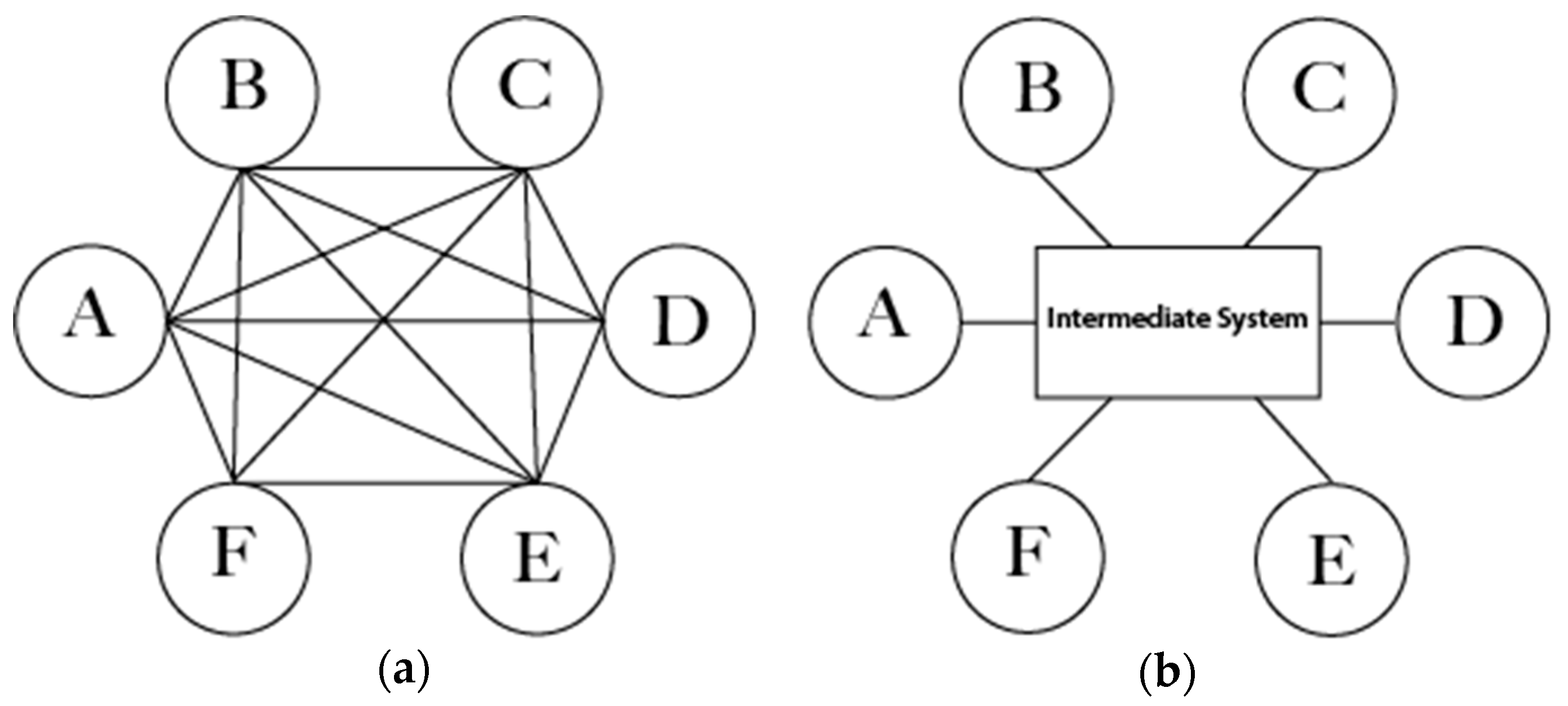
Because the process is connected to different blocks representing its environment, the first solution to design and implement this approach is based on decentralized architecture—a network of connected nodes, where each node has its own data, processes, and applications and manages to collaborate with other nodes [29]. This requires each node to know the system’s information of all other connected nodes, such as interacting data, processes, and applications (Figure 1a). This architecture obviously appears to be hard to achieve, especially when having a large number of connected nodes.
The other solution is based on centralized architecture, which is more reasonable, especially when having many heterogeneous connected systems. In this architecture, an additional independent middleware should be added to the network to manage this compatibility of connected nodes. The middleware between the different nodes is necessary; it should know all the system information of the collaboratively networked systems (Figure 1b).
As an example of the interoperability in decentralized architecture, if node A needs to collaborate with nodes B, C, D, E, and F, then node A should have all acquired information (data, processes, applications) about nodes B, C, D, E, and F. Moreover, each of B, C, D, E, and F nodes should have all the acquired information about node A. This architecture requires more effort to achieve. In such cases, the centralized architecture is more logical, requiring less effort. An intermediate system is essential in centralized architecture. It should have all connected nodes’ information in order to manage the interoperability and data collaboration between these nodes. Connected nodes will then effortlessly exchange data and messages.
4.2. Distributed/Cosimulation Technical Recalls
This approach uses distributed simulation and cosimulation techniques in order to assemble several tools compliant with these two standards. Papyrus can communicate with JaamSim according to DS HLA-RTI functionalities, with an FMU file with the FMI cosimulation standard. Both are needed to form global DMSF architecture.
4.2.1. HLA Technical Recall
HLA operates through the creation of a simulation that is composed of different simulation components. These components are called “federates”. A federation consists of federates, a run-time infrastructure (RTI), and a federation object model (FOM).
A federate can be a simulation system or an interface to a physical system connected to RTI in order to send/receive data and be synchronized with other connected federates. The federation is the set of federates connected to the same RTI, using the same FOM. FOM is an XML file that has the same format as OMT (object model template) of the HLA standard. The objects/interactions and the attributes/parameters are defined in the FOM file and are used to represent the data/events to be exchanged between the federates. The HLA standard defines 10 rules to ensure a successful HLA simulation. The first five rules encompass the functionality of federations while the last five consist of the functionality of the federates.
4.2.2. FMI Technical Recall
The FMI for cosimulation interface [13] is designed for the coupling of both simulation tools and subsystem models. Tools and models should be exported, along with their solvers, by the simulators as binary code. FMI is a standard interface for time-dependent coupled systems composed of subsystems that are continuous or discrete in time [13,30,31]. It provides different interfaces to connect master and slaves and addresses both data and algorithmic exchanges. FMI for cosimulation consists of two parts:
- The cosimulation interface: a set of C functions to control the slaves and enable data exchange between components.
- The cosimulation description schema: a description of component structures in an XML file. This XML file contains “static” information about the model (e.g., input and output variables, parameters) and the solver. Capability flags exist in the XML file in order to characterize the ability of the slave to support advanced master algorithms.
A component implementing the FMI standard is called FMU. It consists of one compressed file containing the XML description file and its implementation in source or binary forms (dynamic library). The master imports one or more FMUs by reading the model description XML file. Using FMI, the coupled simulators hide their implementation details in order to protect intellectual property.
4.3. Simulation Tools
4.3.1. Papyrus
Papyrus is an open-source Java platform providing an environment for developing and editing UML/SysML models. Papyrus also provides tools for executing foundational UML (fUML) models. With its graphical user interface (GUI) tool, it allows users to easily edit UML 2.0 diagrams. Papyrus provides the ability to integrate new profile mechanisms by defining and developing extensions over the basic UML and SysML standards, which increase the reliability and flexibility of this platform. Papyrus also provides a UML model execution plugin: Moka. It is an execution engine compatible with the object management group (OMG) fUML standards and the precise semantics of UML composite structure (PSCS). Moka is integrated into the debugging structure of Papyrus (based on Eclipse) in order to provide the user with control, observation, and animation functions for model execution. Moka can also be extended to execute custom behaviors or support UML profiles customized by the user. Among different process modeling tools, Papyrus has been selected for this project because it proposes easy process modeling and simulation to the enterprise that looks for a tool to represent and analyze the chain of activity they want to set up and then observe process behavior (regarding time and other performance characteristics).
4.3.2. JaamSim
JaamSim is a free Java-based open-source simulation package developed by an Australian Engineering company named Ausenco. The main feature that differentiates JaamSim from other off-the-shelf commercial DESs is that users can design and make their own high-level object palettes [10]. When JaamSim is launched, a graphical interface appears. Users can use this graphical interface to add entities and create the simulation model or write/edit a configuration file (.cfg) in which all entities/objects can be added and configured. Some users might prefer the graphical interface to drag and drop their entities and configure them on GUI (graphical user interface). Others, especially programmers, would find it faster and easier to create/edit the configuration file (.cfg). This software is used in this research, instead of other simulators, due to its transparency, reliability, capability, and, most importantly, because it is an open-source software that can be configured to interact with external third-party applications.
5. Contribution to a Modeling and Distributed Simulation Framework
5.1. Conceptual Contribution
This work will contribute to solving interoperability problems (internet source, connected objects, external tools).
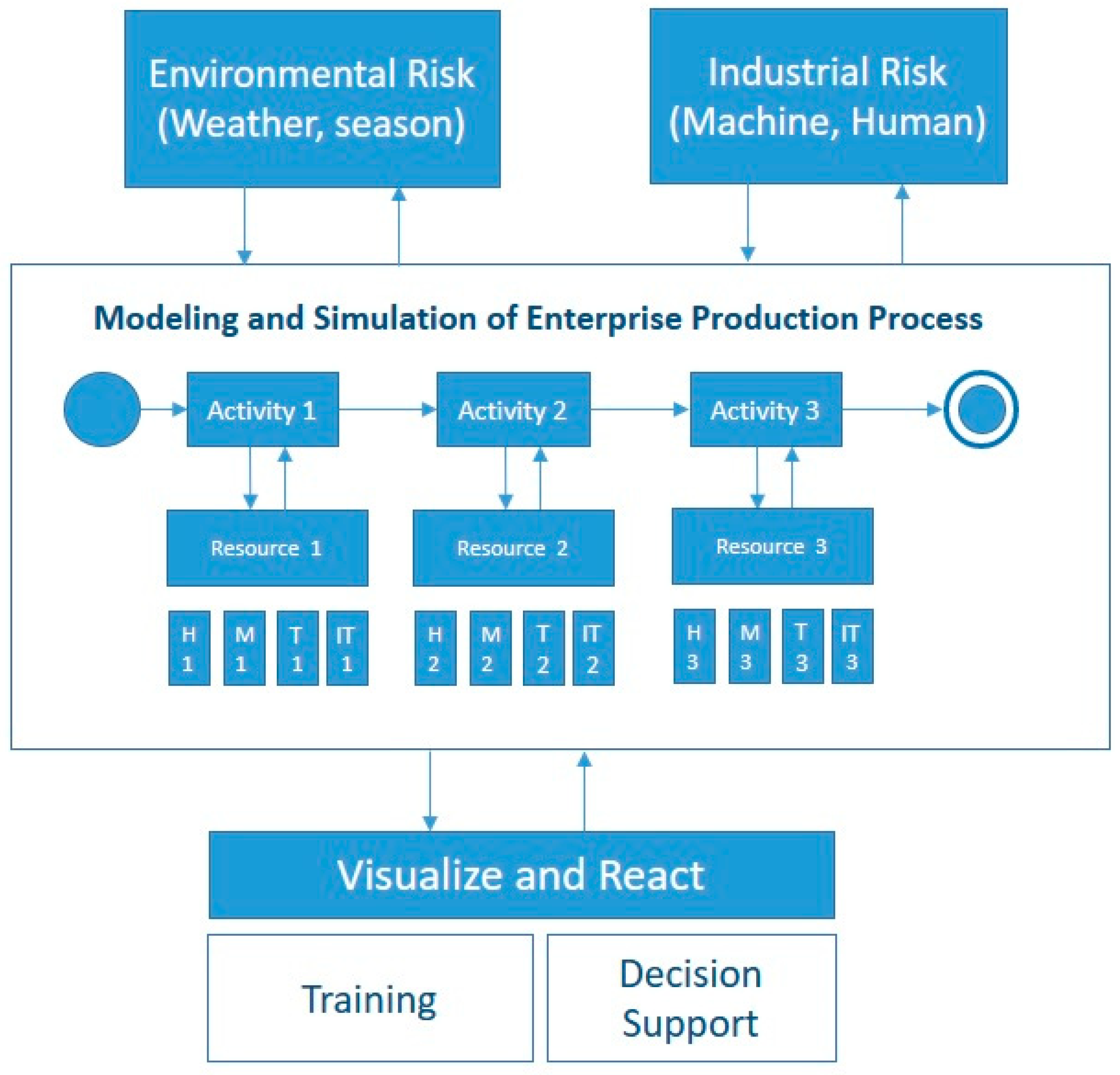
After solving interoperability issues (e.g., heterogeneous functions and procedures, connected systems and objects, external tools), this contribution provides a framework that integrates all necessary functionalities that allow enterprises to overcome the barriers listed in the problem statement paragraph. The enterprise production system should first be modeled. Each of the modeled activities can share, subscribe, and publish different resources such as human, machine, time, and IT resources, annotated as H, M, T, and IT in Figure 2. The modeled system is affected by several external hazards or simulations. External systems have been developed to experiment with environmental risks (weather constraints, delivery issues, or emergency situations) and industrial risks (uncertainty of human and machine resources). The generation of such hazards affects the modeled enterprise production system and helps the decision-makers to track the consequences of each hazard. Moreover, hazardous events can be generated during the simulation run, and output results are visualized in real-time on a tool that displays all of the KPIs needed to track the simulation advancement. This framework is considered a training environment for project managers to minimize waste and non-value-added activities, as well as possible time, quality, and financial losses. Thus, it is considered a decision support tool in order for industries to test each process or activity modification before implementing it in the real environment.
5.2. Technical Contribution
In this section, an architecture composed of six main components that will be presented hereafter is proposed:
- Modeling and simulation orchestrator component: Papyrus modeling tool and Moka execution engine to model and orchestrate the main process.
- Risk management tool: Injects hazards into the distributed simulation.
- Discrete event simulation tool: This JaamSim-based DES tool runs the local manufacturing behavior.
- Display tool: Presents simulation results.
- Distributed simulation implementation:
- ⚬
- HLA implementation: orchestrates Papyrus and JaamSim.
- ⚬
- FMI implementation: orchestrates Papyrus and FMU-Java App.
- ⚬
- Global orchestration: presents the global architecture process.
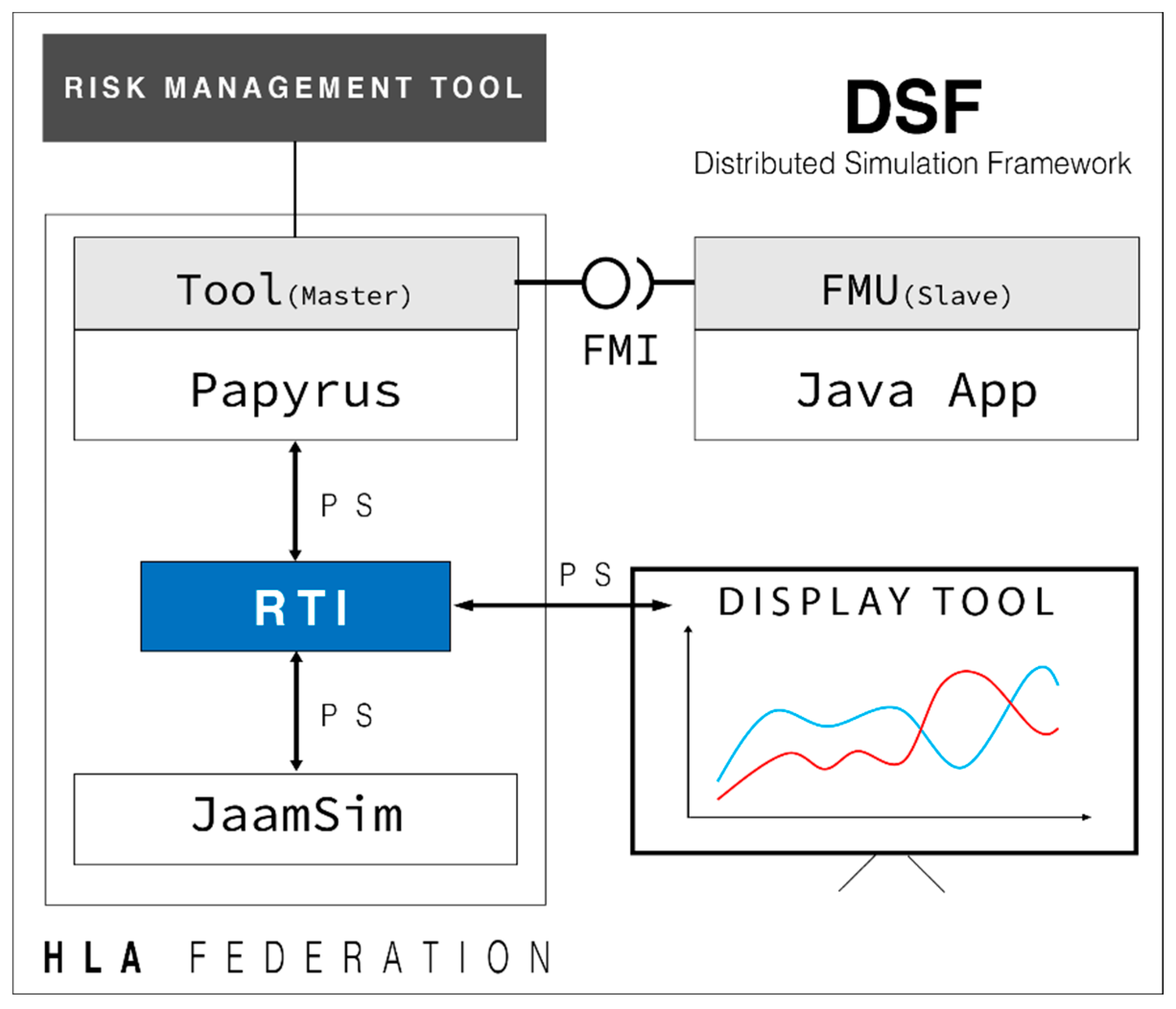
Figure 3: the distributed simulation framework introduces each of the components used to develop the whole distributed framework. These components are detailed in the following subsections.
5.3. Distributed Simulation Framework Components
5.3.1. Modeling and Simulation Orchestrator Component
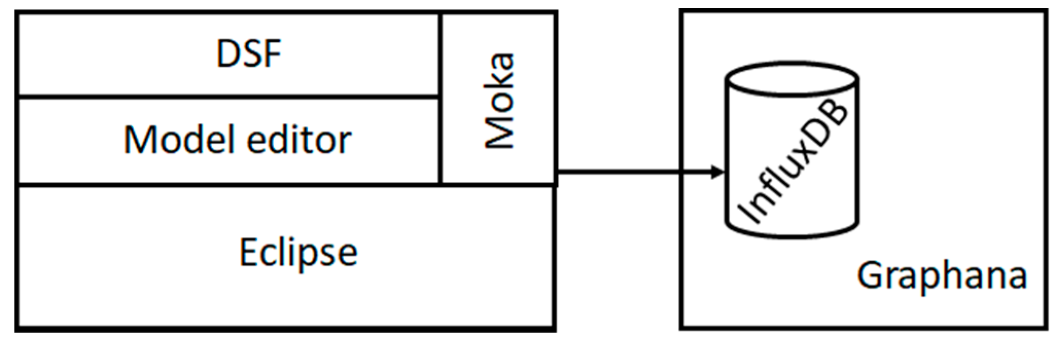
As per Figure 4, a new layer was developed, called the distributed modeling and simulation framework (DMSF). This layer inherits Papyrus functionalities and is able to communicate with a Moka custom extension.
The DMSF is connected to its child layer using an inheritance approach [32]. It is a UML profile implemented over the UML notation standard that allows users to add semantic values to UML tasks. Those data contain information about the interoperability configuration between the connected tools.
According to this architecture, each layer has its own functionalities. The Eclipse base provides a powerful and modular IDE, allowing implementation on the upper layers. The Papyrus editor allows developers to customize UML profiles. The Moka layer is the execution component of Papyrus; it can also be expanded to execute customized UML profiles.
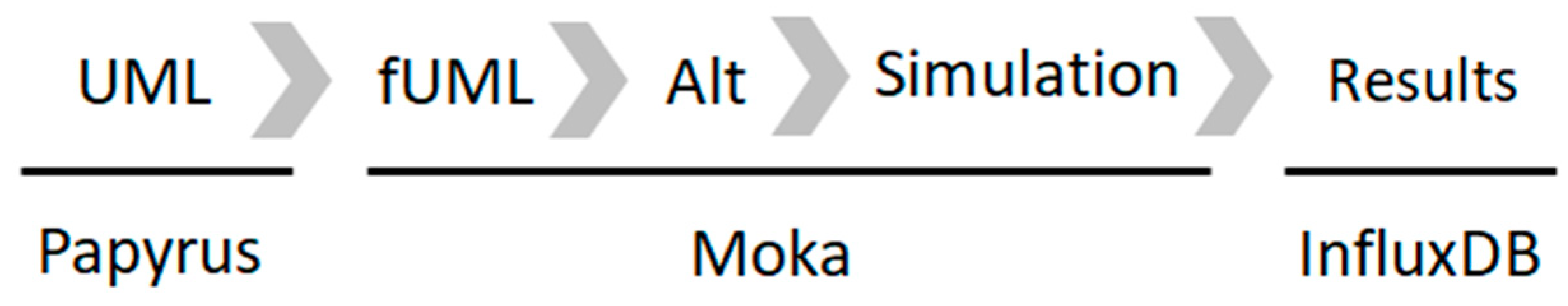
The UML diagram, designed with the Papyrus graphical editor, is sent to the Moka run-time module to be executed (Figure 5). Moka is compatible with UML and foundational UML (fUML) standards. fUML is a subset of the UML language that has standardized execution semantics maintained by the object management group (OMG). An fUML model is, therefore, executed as a programming source code (e.g., C, Java). A standardized textual syntax for fUML, called “action language for fUML” (Alf), also exists. This syntax is particularly used to define more detailed behaviors for a finer granularity simulation.
fUML is a bridge language that allows a translation from graphical to executable code, executed by the Moka run-time (Figure 5).
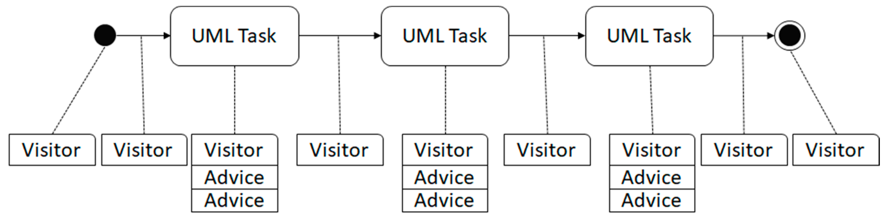
The Moka engine uses the concepts of “Visitor” and “Advice” (Figure 6). A Visitor is a Moka object, automaticaly instantiated for each element of the UML diagram (e.g., start points, stop points, transitions, steps). It can be associated with one or more Advice. An Andvice is a Moka object that allow to add behaviors during the execution time.
During the execution phase, the engine collects every advice and visitor contained in the model (Figure 6). A visitor can contain one or several pieces of advice. The visitor is used by Moka at the beginning and the end of each UML element. Moka reads the state of the visitor. The visitor’s state can be “starting”, namely, the task is about to start, or “ending”, namely, it is about to end.
In the case of a starting state, the engine loops on all Advice associated with the visitor. Calling the canStart() method asks for authorization to execute the visitor. It calls this method for each Advice. If all Advices answer favorably, it executes the start() method of the advice class. Finally, the task is executed by the engine.
The task is not yet accomplished; once executed, the visitor state turns to “finishing” and waits for authorization from the engine to finish. If the task has no time constraint, the execution process sends a signal to the Advice in order to terminate the task. The engine terminates the Advice by calling the canFinish() method. If a task termination is accepted, the finish() method of the Advice is called, and the next UML element is processed by the execution engine.
Specific behaviors are added to the above methods. Implementation of HLA, FMI standards, and interactions with the external risk management tool is declared and managed in these methods. The main idea of this chapter is to add and develop a new Moka extension for each standard and functionality. Consequently, the component will have several layers of the execution engine extension:
- HLA layer—JaamSim.
- FMI/FMU layer—delivery process.
- Java/SQLite layer—risk management tool.
5.3.2. Risk Management Tool
According to ISO 31000, risk is the “effect of uncertainty on objectives”, and an effect is a positive or negative deviation from what is expected. Hence, the risk impacts the tasks to which the objectives are assigned in terms of performance to reach.
In industry, risk management is made of several steps that are necessary for dealing with hazards during a project lifecycle.
Setting up the context involves identifying the constituents, the environment of the system, and the various risk criteria for the rest of the process. As mentioned in [33], several steps are necessary to identify and process risk:
- Identifying and establishing a risk inventory that could potentially affect the system.
- Risk analysis to define its causes, consequences, and relationships with other risks.
- Risk evaluation to prioritize them. Map and describe the risks both qualitatively and quantitatively (e.g., probability of occurrence, impacts) in order to rank them according to their priority.
- Risk treatment consists of recommending treatment options in order to maintain a level of risk that meets requirements.
- Risk monitoring for studying the impact of treatment on the system.
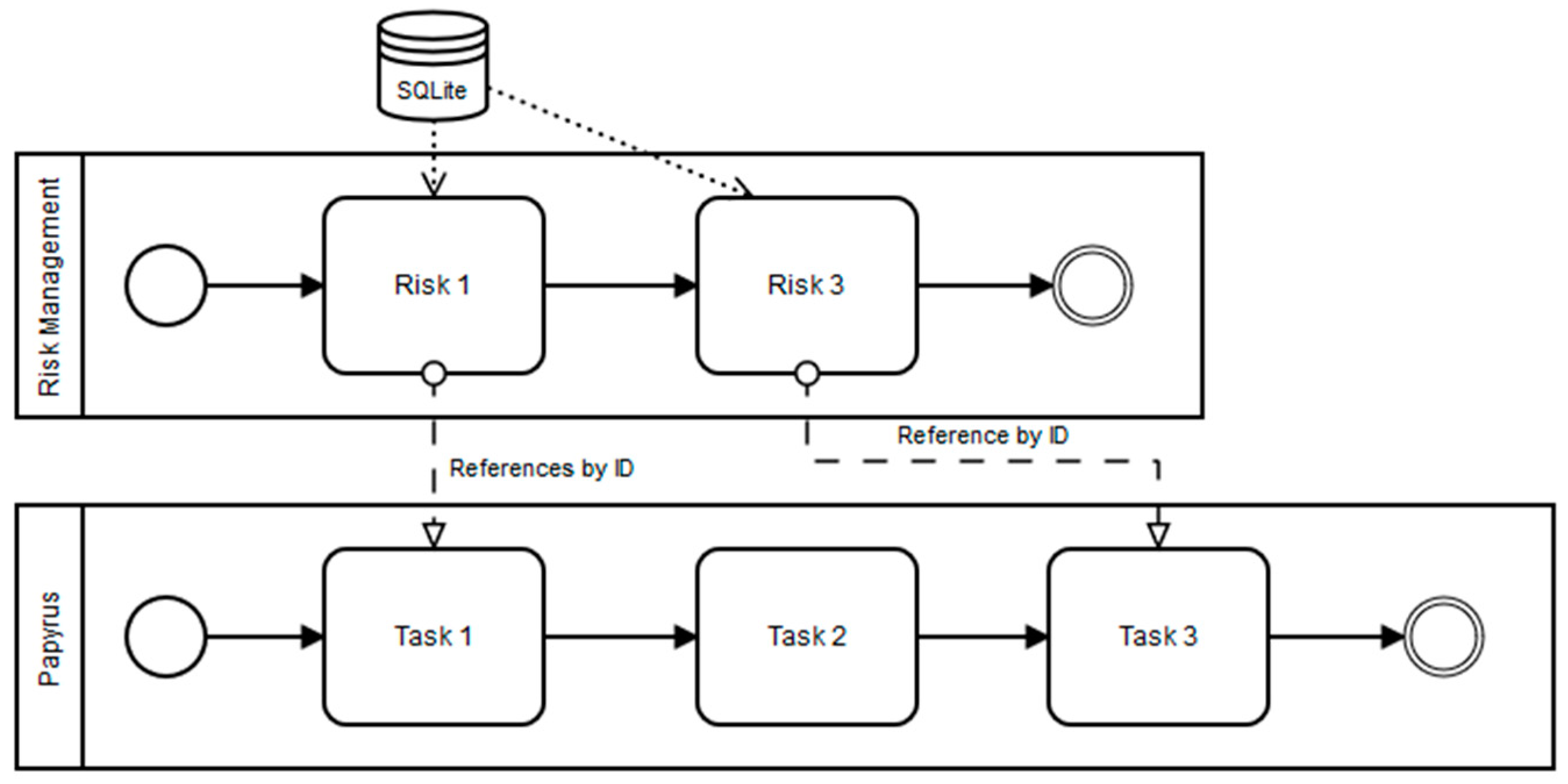
The risk management tool is a module designed for including a risk treatment over the production system’s simulation. This separation allows engineers to model the system on a tool and define rules that will impact the system in a separate module [34]. Risk occurrence and severity must be observed or calculated by experts, and then described to the system through equations and algorithms. The objective is to implement a connected adhoc system communicating with the simulation engine (Moka) during simulation execution. This system can insert assigned hazards as tasks of the main Papyrus model by expanding or reducing the simulated duration. As presented in Figure 7, the risk management tool is a set of tasks connected to the main Papyrus model, as well as to an SQLite database containing a list of risks associated with impacts (in terms of time). Links between the Papyrus model and risk management tool are made using the ID reference system.
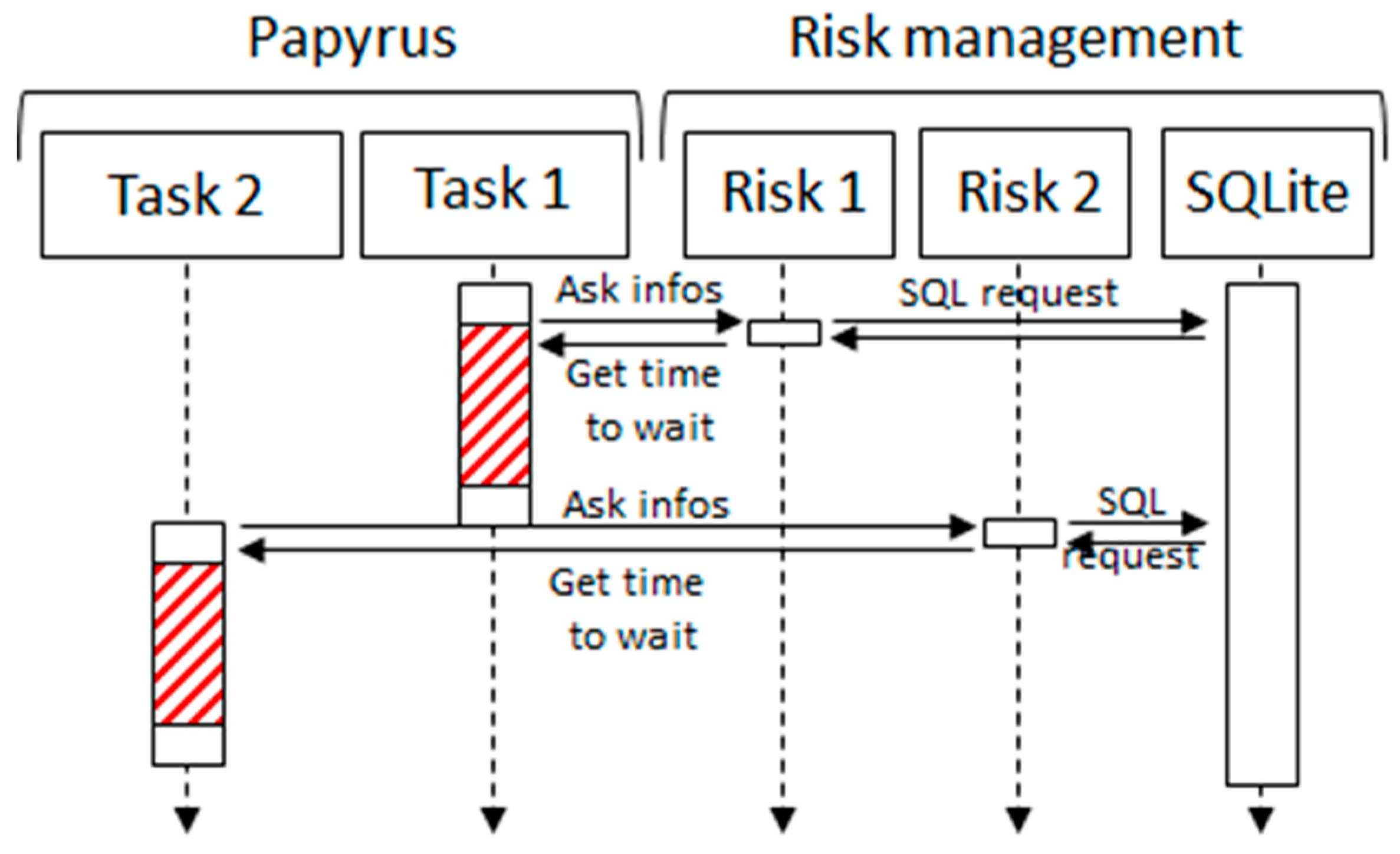
The link between Papyrus and the risk management tool is realized by adding a UML profile over the UML diagram in order to add an ID to the tasks of the Papyrus model (Tasks 1 and 3 in Figure 7). The Moka extension is also customized to execute the risk management module on every task that extends the custom UML profile. Tasks of the risk management tool contain equations based on statistical laws provided by the company’s engineers. Randomized values are also added in order to generate hazards in the Papyrus model. During the execution process, the behavior described in Figure 8 can be observed.
When Papyrus executes a task, it will be associated with a native execution duration (normal processing time of a machine in the production system). This duration is extended or reduced by its associated task that exists in the risk management module. This associated task is developed by engineers in order to describe the probabilities of issues.
Risk setup is done with an SQL database that allows users to store risk laws and impacts that are executed during the simulation by the risk management module. Each task is represented by a unique ID. In our example, Figure 9 and Equation (1) illustrate delivery time simulation for the shop floor supply. For instance, Task1 (delivery) is represented by Risk1 (potential delivery issue) (Figure 8). The equation representing potential late delivery for the product of Task1 is provided by the manufacturing expert. Equation (1) represents a law of temporal degradation in the simulation regarding late delivery. This equation is used in the case study in Section 6. In our example, Task1 has a native simulated duration represented by t1 in Equation (1). This duration is affected by the normal distribution f(x) of the equation below. Once a risk has been evaluated by an expert, it is characterized by using the following equation:
In this example, the execution time of Task1 during the simulation will be modified at the execution time, depending on several parameters:
- x: a random number between −1 and 1 generated at the engine initialization. This number is generated with a seed, which allows the user to reproduce the simulation with the same random generation.
- σ (can also be called risk1.sd): standard deviation represented as a variable that is predetermined but still modifiable by other risk laws (a consequence of a risk can increase or reduce another risk by changing this attribute of the equation). In our example, this variable is set to 0.07.
- µ (can also be called risk1.m): mean of the distribution, also set as a variable to 0, but can be changed by other risk impacts.
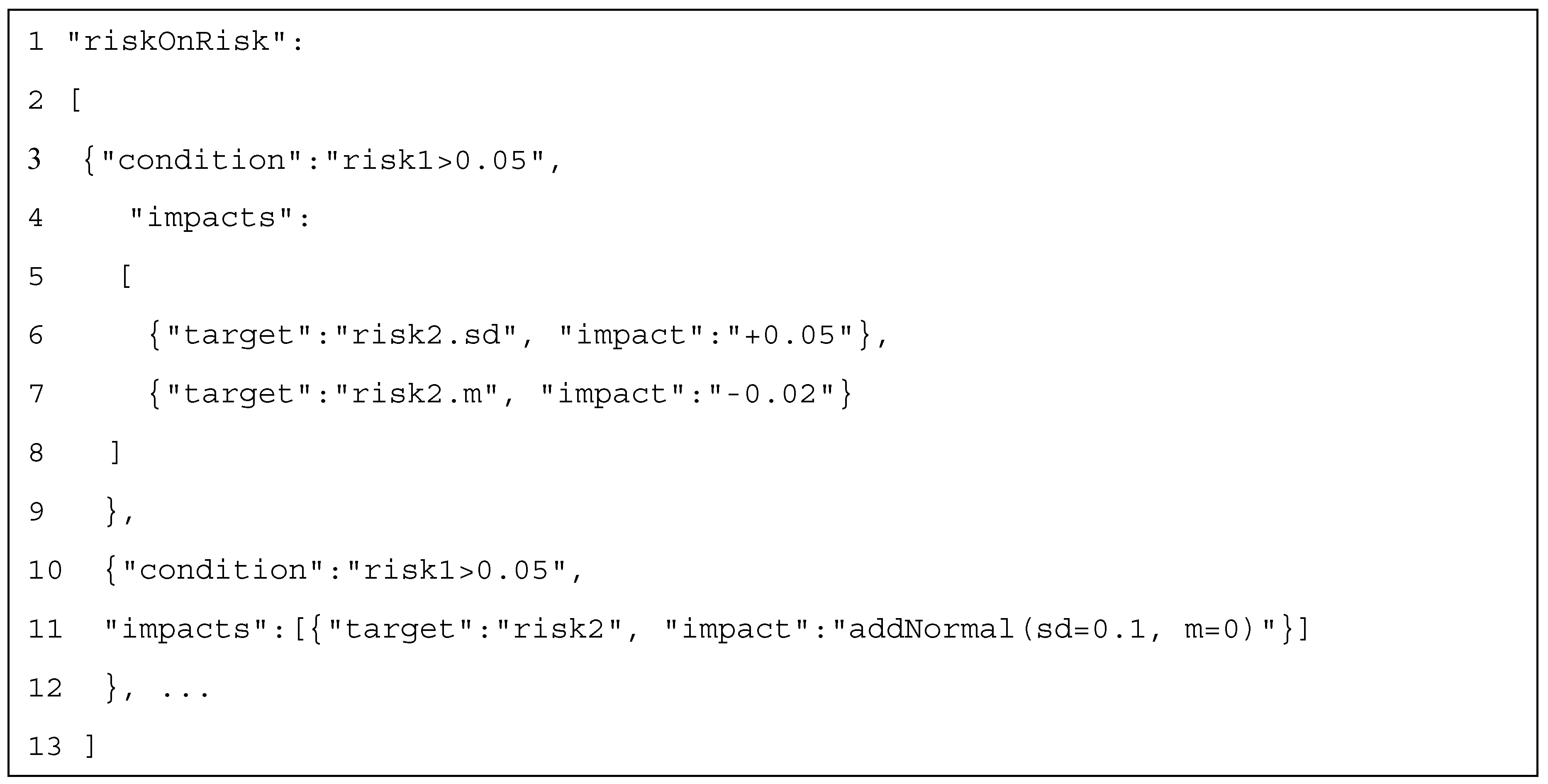
In our example, the simulation time of t1 will be modified by a normal distribution law according to several parameters. Once mathematically described, risk and hazard will be formalized in xml format. This file enables the engineer to specify risk severity for the simulation according to data obtained or statistics obtained from experience. As indicated, the simulation time of this task will be increased or reduced by a value between −1 and 1. By multiplying the simulation time of Task1 by the equation given by the user, a risk can impact a task execution. Risk can also impact or generate other risks. This can be done using a json file (Figure 9) that describes interactions between existing tasks and introduces new generated risks during the simulation run. In addition, new rules can be added to the json file during the simulation execution. For instance, an unfortunate event can add or modify an already existing risk.
In Lines 6 and 7, the two variables risk2.sd and risk2.m will be modified if risk1 is greater than 0.05. One can also create a new risk triggered by the result of risk1 (as per Line 10). If the result of risk1 is greater than 0.05, it adds a new normal law to the equation of risk2. Moreover, risk2.sd and risk2.m become variables that can be modified by other conditions.
5.3.3. Discrete Event Simulation Tool
This tool is based on the DES JaamSim. It provides built-in objects for building and simulating models. Users with Java programming knowledge can add new objects and edit the existing built-in objects. The JaamSim model can be launched automatically from the terminal or command line. Tags can be added to the command to start the simulation and exit right after the completed simulation has been run to minimize GUI during the simulation run (the simulation will run much faster as visualizations are not required) or to run the simulation without GUI (this tag is very useful when running the simulation on a server without graphics). The GUI of JaamSim is divided into six main components. The first component is the control panel window that offers multiple simulation control features. The second is the model builder in which the user can find different objects and choose the entities needed to build the simulation model. In the model builder palette, users can choose different graphic objects, probability distributions (uniform, triangular, exponential, gamma), basic objects (TimeSeries, ExpressionLogger, FileToVector), objects related to process flow (EntityGenerator, Server, Queue, Resource, Branch), calculation objects (Controller, Polynomial, Integrator), and fluid objects. This project was developed on version 2018-05 of JaamSim. It can be installed on Windows or Unix operating systems.
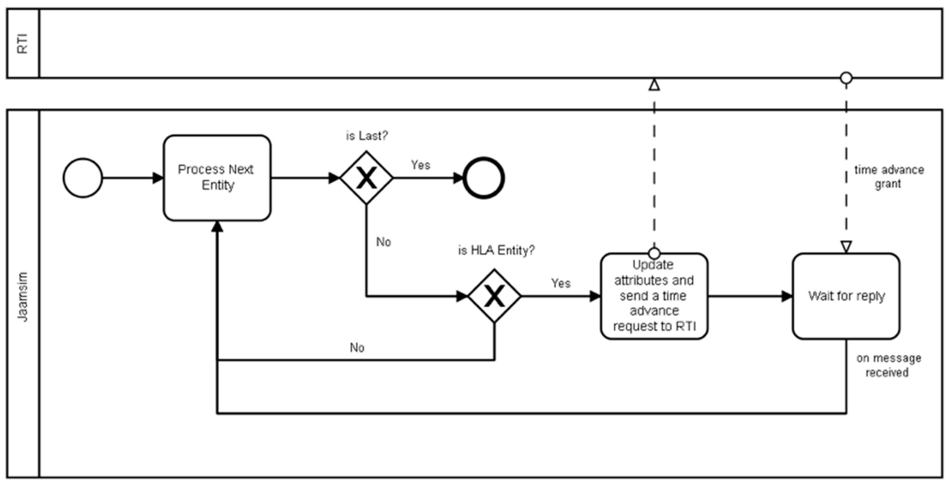
JaamSim was not originally designed for communications to external systems and is not fitted for DS; it is viewed as a black-box simulator. This contribution uses a modified version of JaamSim that will allow us to connect JaamSim components to external heterogeneous applications in order to collaborate with external systems and exchange data. As it is an open-source software, it was possible to edit its Java code and add new modules in order to make it an HLA-compatible DES. As described in Figure 10, this work added a method to all JaamSim objects that reads all attributes assigned to JaamSim objects; if an entity has an attribute called “waitRTIOrder”, it will be considered as an HLA entity able to collaborate with external systems and exchange data. This entity then asks for time advancement from RTI; in such cases, the federate updates the attributes and asks for time advancement. After this step, it will wait for the RTI reply in order to advance in time and process to the next entity. If no “waitRTIOrder” attribute exists, the next component will be processed. This process is repeated until the end of the simulation.
5.3.4. Display Tool
JavaFx was used to develop the DMSF display tool and deliver the graphical user interface to the user. This tool is launched first while some services run in the background to join, as a separate federate, the federation execution and the FOM XML file, where all objects/attributes and interactions/parameters exist. The display federate gets the output data and time from the Papyrus federate and draws the graphs that help the user in tracking the output results in real-time and during the simulation run. JFreeChart is a Java library that is used to draw the graphs.
The output data are the results sent from the JaamSim federate to the Papyrus federate through the publish/subscribe mechanism of the HLA standard. When any of the federates call the updateAttributeValues() method to update its attributes, the method reflectAttributeValues() in the display federate will return the updated values that will be, in turn, printed to the real-time graphs.
The output results that are tested in the developed DMSF are the total work in progress (WIP), the lead time, and the production throughput values during the production process. These aforementioned results will help the user to check whether production is on the right track or should be improved for better results.
5.4. Distributed Simulation Implementation
5.4.1. HLA Implementation
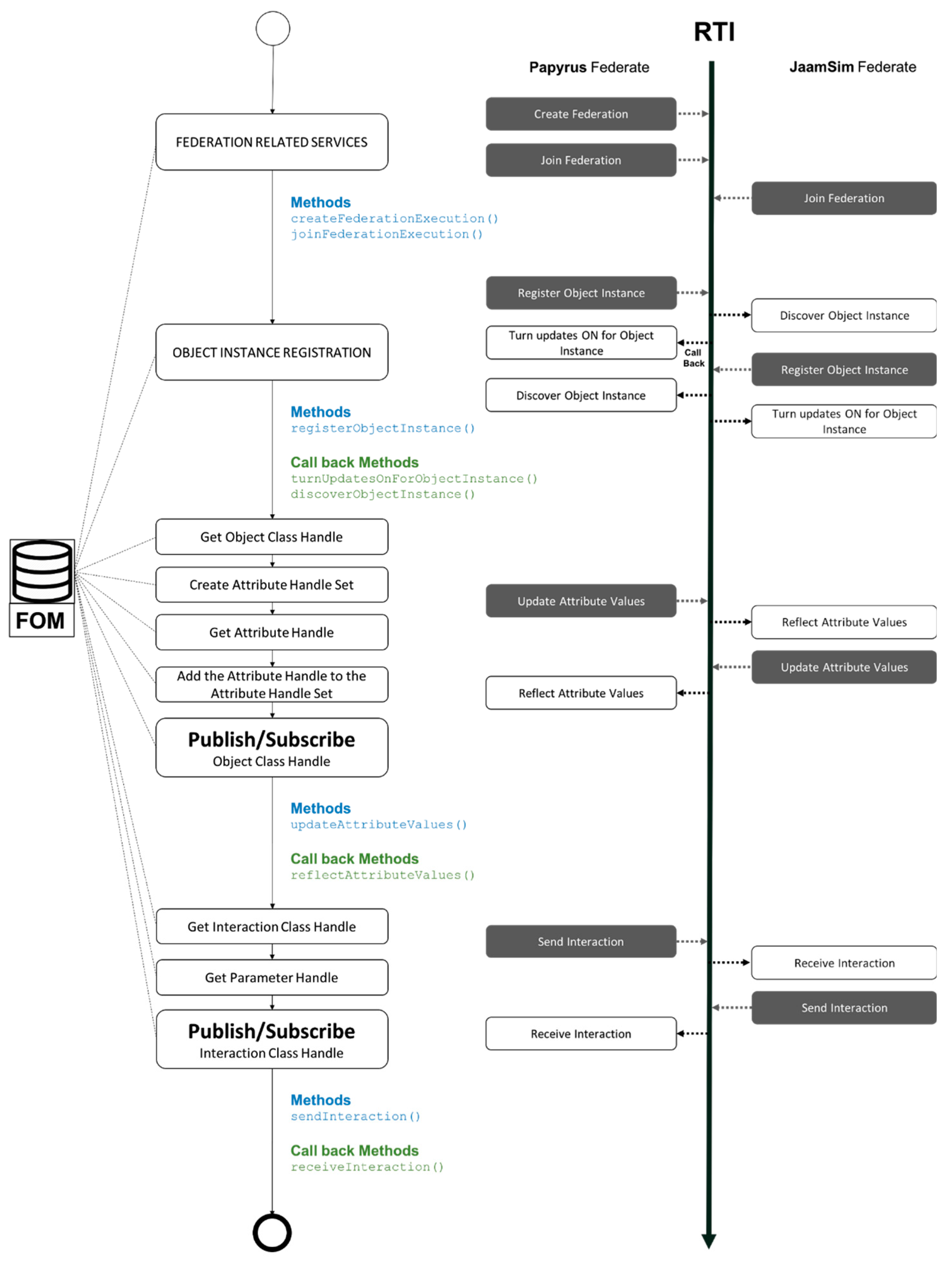
The HLA development part of DSF is based on the Java pRTI library [35]. Different steps are required before starting the data exchange and communication between the federates. The methods required for each of the implementation steps can be found in Figure 11. Some methods provoke callbacks from RTI in order to access other specific methods in the connected federates (Figure 11).
The first step is the federation-related services, where a federation is created and then joined by the federates. For instance, Papyrus creates the federation using a federation name, links it to the corresponding FOM file that has all the information about the data to be exchanged between these two connected federates (objects/attributes and parameters/interactions), then, as federates, Papyrus and JaamSim join the newly created federation.
The second step is object instance registration; the method “registerObjectInstance()” of the RTIambassador is used to notify RTI that a new object instance has been created. When the object instance is registered, connected federates discover this object instance and then turn on the updates for the object instance through the RTI callback that accesses “discoverObjectInstance()” and “turnUpdateONForObjectInstance()” methods of the federates. Before the publish/subscribe phase of the object/attributes, the federate should get the object class handle, create the attribute handle set, get the attribute handle, and then add the attribute handle to the attribute handle set.
Each of the connected federates publish the objects/attributes needed by the connected federates and subscribe to the required objects/attributes from the connected federates. The “updateAttributeValues()”method and the “reflectAttributeValues()” callback method are used in order to exchange the object/attributes. As for the publish/subscribe of interactions/parameters, only two steps are required before starting the send/receive processes of interactions/parameters; get the interaction class handle, then get the parameter handle. The methods used to send and receive interactions/parameters are sendInteraction() and receiveInteraction() (callback method).
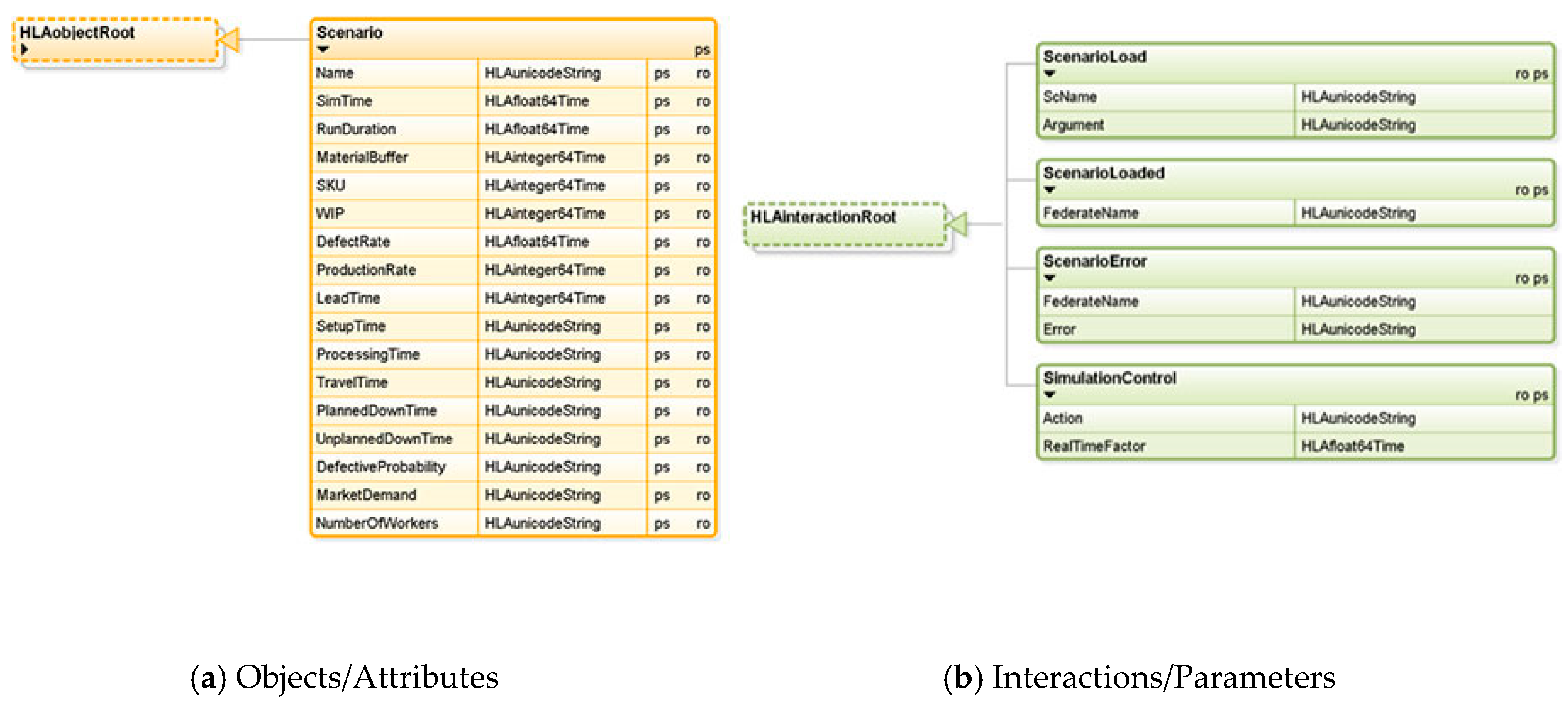
The FOM file has been created, as per Figure 12. The object class “Scenario” has the attributes “Name”, “SimTime”, “RunDuration”, “LeadTime”, “SetupTime”, and “ProcessingTime”. The scenario name of the simulation run is represented by the attribute “Name”, the simulation time of JaamSim during the running simulation is represented by “SimTime”. Each of the attributes in the “Scenario” object class has a data type defined in the FOM file (e.g., HLAunicodeString, HLAfloat64Time, HLAinteger64Time).
The interactions have also been created to build the DMSF (ScenarioLoad, ScenarioLoaded, ScenarioError, and SimulationControl (Figure 12b). The master federate sends the scenario name to load (ScName); if the scenario is loaded, the model federate sends back the interaction “ScenarioLoaded”, otherwise, if the scenario does not load, the model federate sends the interaction “ScenarioError” to the master, along with the error which has occurred. One or more parameters for each of the aforementioned interactions are proposed; for instance, the “ScenarioError” interaction has two parameters—the “FederateName” and the “Error” occurred. The attributes and the parameters are exchanged between the federates based on the publish/subscribe mechanism of the HLA standard (“p” for publish, “s” for subscribe, and “ps” for publish and subscribe).
5.4.2. FMI Implementation
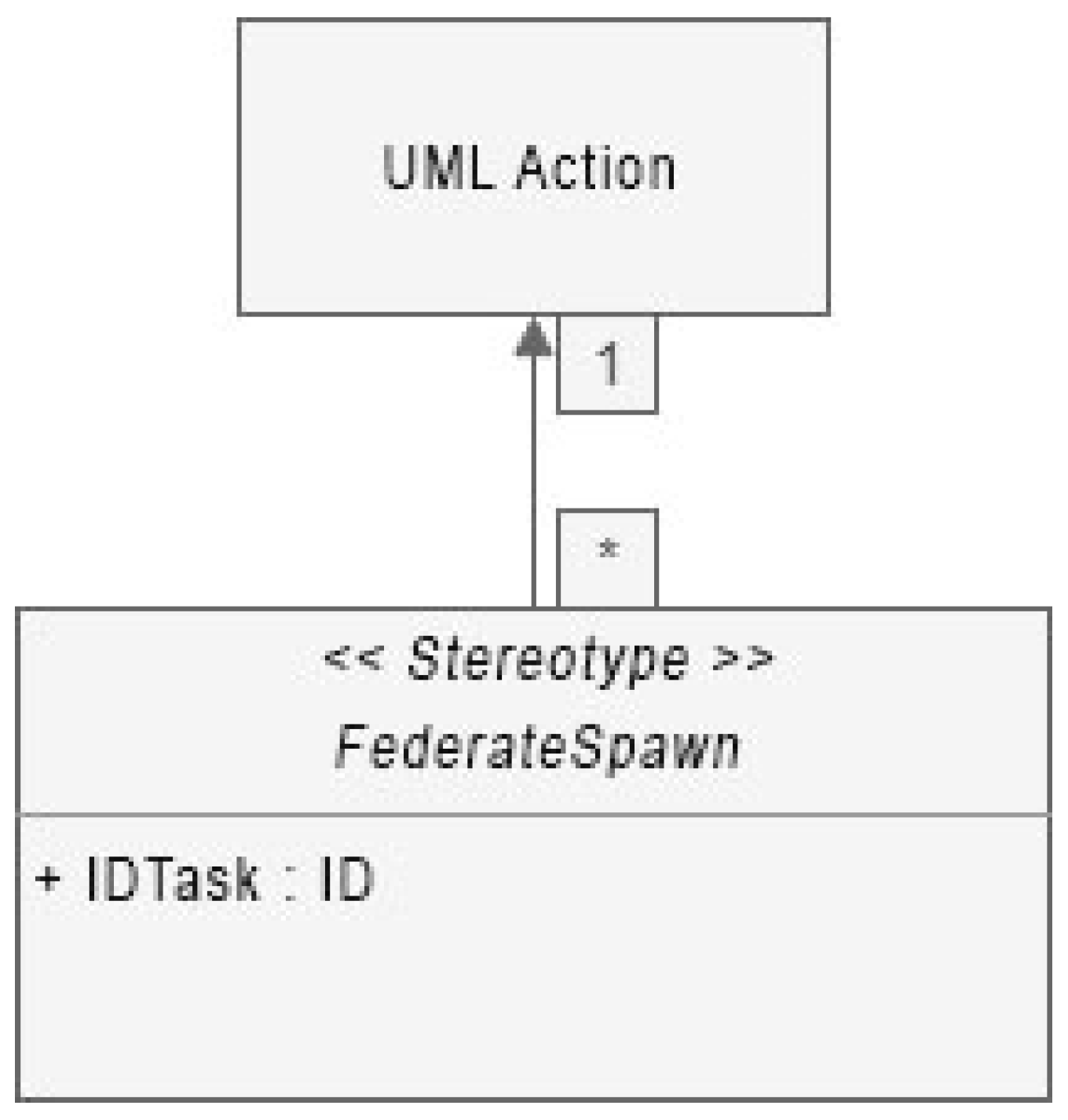
The eclipse modeling framework (EMF) generator allows us to create one or several UML profiles attachable to the model. This profile contains a stereotype with parameters (Figure 13) that will be filled by users and is accessible by our custom extensions.
The EMF generator contained in Papyrus enables the generation of source code for a Moka extension. This code is inherited from the Papyrus execution engine class. Based on it, one is able to override functions of the engine in order to modify its behaviors:
- doPresRunActions() is a function that will be launched at the start of a simulation. This function is launched before browsing the graph designated by the user and before instantiating the visitors and their advice. It is via this function that the classes can be initialized, allowing the management of HLA interactions.
- doPostRunActions() is launched at the end of the simulation. This function is used to export simulation results.
- getAdviceFactories(): Called at engine start-up, it retrieves the list of advice normally instantiated by the engine at that time. In order to overload this function, add by the cumulative effect the advice from this engine extension. This addition is done via the FailureAdviceFactory class.
It is through this addition of advice that functions can be added to Papyrus on actions designated by the user. By applying the stereotype on some UML tasks, the user will add custom advice and thus, modify the behavior of Moka during the model execution.
From the list of AdviceFactories, a new advice associated with each behavior is added for the needs of Papyrus: one for HLA-JaamSim, one for the delivery process, and one for the risk management module. Each Advice must declare canStart() and canStop() functions, which will be executed by the Moka engine during the simulation. These functions are used to create entry points to HLA and FMI standards. In these functions will be interactions with a FederatesManager, who will use RTI functions to communicate with JaamSim through HLA.
To manage a cosimulation with the FMI standard, some functions must be used from the javaFMI library:
- Loading an FMU file can be done by calling the “Simulation(String)” class.
- doStep(double) is a function used by the master to step forward in the simulation time of FMU. The parameter represents the elapsed time to step forward; then, every output variable will be changed.
- getState(String)/setState(String) are functions that allow you to save and restore the global state of the simulation (these functions will save the current variables’ states of FMU).
- The reset() function reloads FMU to its initial state.
- The terminate() function ends the simulation.
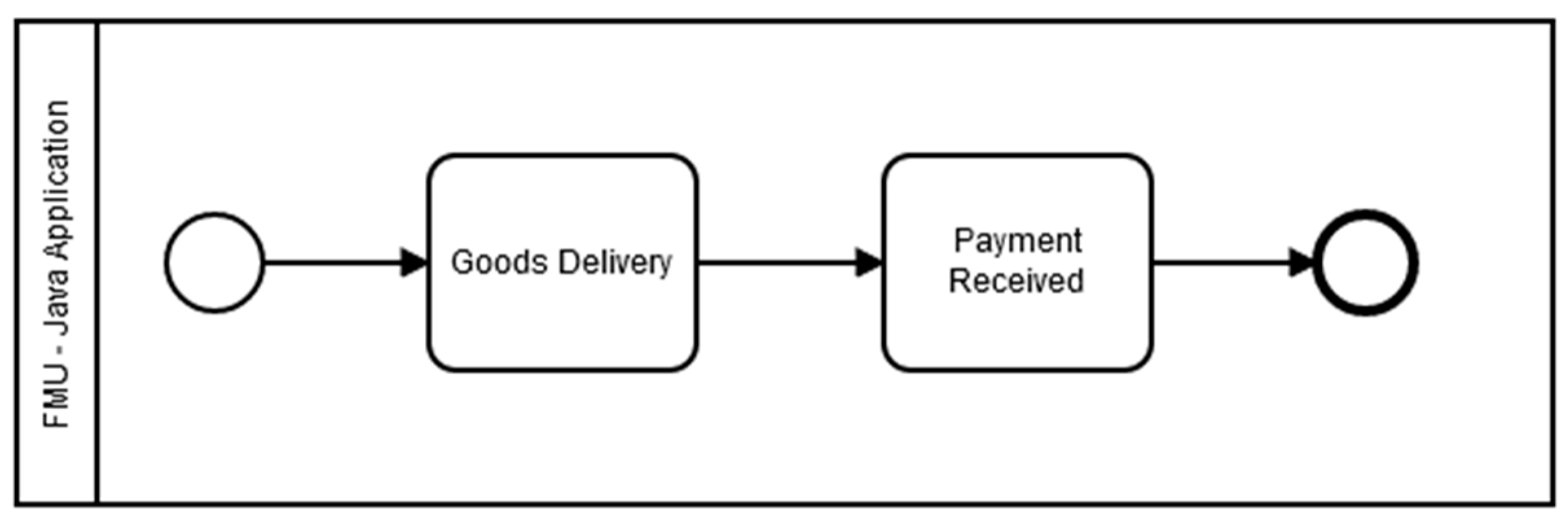
This work has developed a simple FMU for a cosimulation model with the JavaFMI library (Figure 14).
This model calculates the delivery time of goods based on their numbers, location of the manufacturer, and location of the client (Figure 14). In the first task, the model determines the distance between the two points, thanks to a Google maps api request, which determines distance, and time consumed by the simulation to deliver the goods.
The second task determines the time simulated for sending an acknowledgment of receipt from the customer.
5.4.3. Global Orchestration
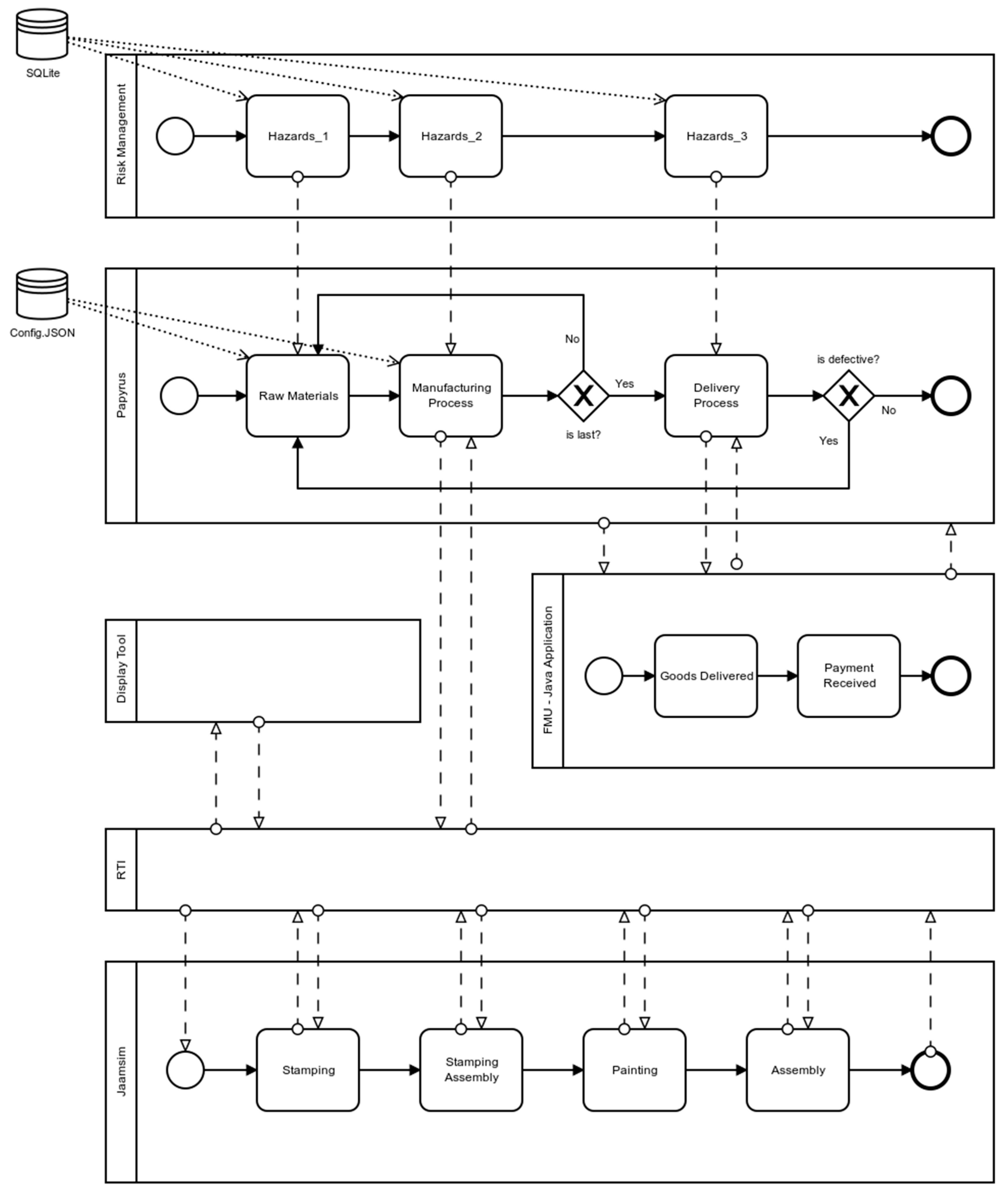
Figure 15 introduces the process-oriented model of DMSF using BPMN (business process model and notation), a business process modeling standard, and a flowcharting technique that provides a graphical notation to define and describe business processes. Papyrus and JaamSim are configured as two separate federates running on different machines/workstations and having different IP addresses. The communication between those two machines is based on the publish/subscribe mechanism of the HLA standard on a port number defined in the code when the federation is created/joined. The firewall might block the communication on the aforementioned port number, so the inbound/outbound rules should be configured to allow the communication on the RTI-defined port. The objects/attributes and interactions/parameters are needed to properly control, configure, and then run the company’s simulation model on JaamSim.
After the federation creation step, Papyrus and JaamSim will join this federation as two separate federates. Papyrus gets the raw material data (number of goods, type of goods, client details) from a JSON file, then starts the simulation of the developed model using the interaction/parameters mechanism of HLA. Papyrus sends, in parallel, all data inputs needed by JaamSim using the object/attributes mechanism of HLA to run the simulation model (e.g., raw materials data, processing time and setup time for each machine, travel time between machines, planned/unplanned downtime of each machine, number of operators on each machine). The simulation case study used to experiment on DMSF efficiency is detailed in the next paragraph. The output results of the simulated model are published to the RTI. The display tool, connected to the federation as a separate federate, gets those results using the subscribe mechanism of HLA, then draws the respective graphs that help the user to track the production process of the company. When goods are ready for delivery, JaamSim publishes an interaction in order for Papyrus to start the delivery process that will also be simulated on a Java application connected through FMU to Papyrus. The adhoc system, communicating with the Moka engine, introduces hazards to each of the tasks of the Papyrus model. In this way, managers and decision-makers can test and experiment on the reliability and efficiency of their existing production systems.
6. Simulation Case Study and Results
The DMSF developed framework was tested on an automotive production model [36], simulating the different stages of the manufacturing process at the job shop floor level. The first step in automotive production is the stamping process, where steel sheet rolls are rolled out and then cut into pieces, passed on a press line to be stamped, drilled, punched, and cut in order to make all the components of the car body. The next step is the assembly of stampings; steel sheet parts (body sides, base) are assembled by spot and laser welding. The assembly of aluminum parts, such as covers and doors, is carried out by robots. The painting stage follows the assembly. Since a single layer is not enough to prevent corrosion, the case passes through several layers in the paint department. In order to guarantee soundproofing, but also the tightness of the vehicle, a mastic will be applied first. After this, the primer, lacquer base, and varnish layers are applied. These give the case its final appearance. To complete the process, wax will be injected into the pores of the vehicle’s body. Again, the objective is to ensure corrosion protection. After the painting, the body will be equipped with all the necessary equipment: engine, driving position, dashboard, headlights, seats, mirrors, interior trim, and wheels. The assembly remains the hardest step and requires a concentration of know-how. Of course, before assembly, the logistics department will ensure that all car components are ready and compliant. In order to avoid any unpleasant surprises leading to disputes, the car must be built with the highest quality standards and, above all, meet safety standards. Therefore, quality control remains essential. This control applies to every stage of the construction process. Stamping, sheet metal work, painting, and assembly must strictly comply with construction specifications. Before delivery or sale, the car is tested on benches, but also on the road. If the vehicle passes these last quality checks, it can be sent to the point of sale.
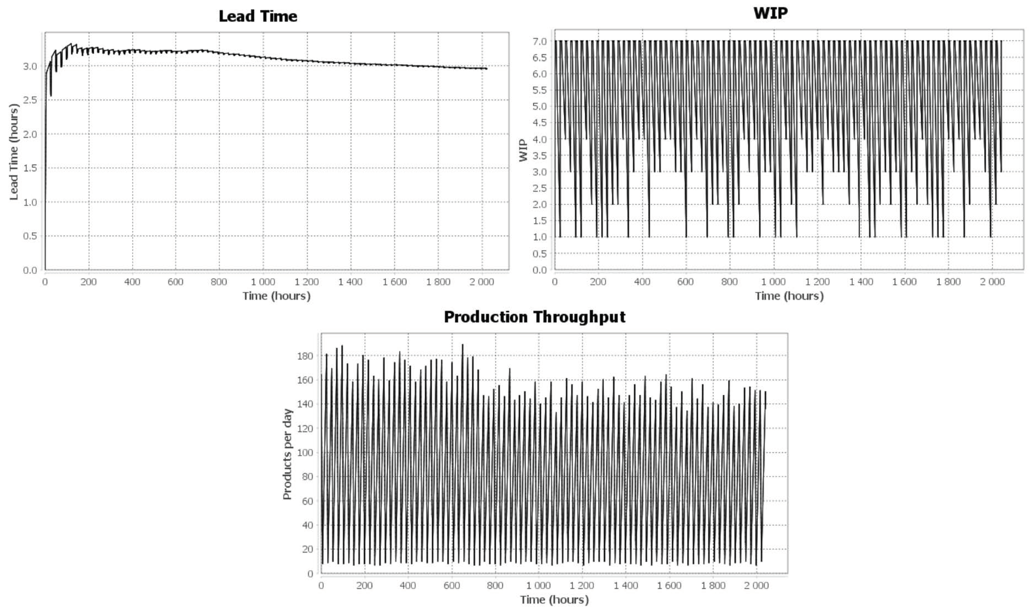
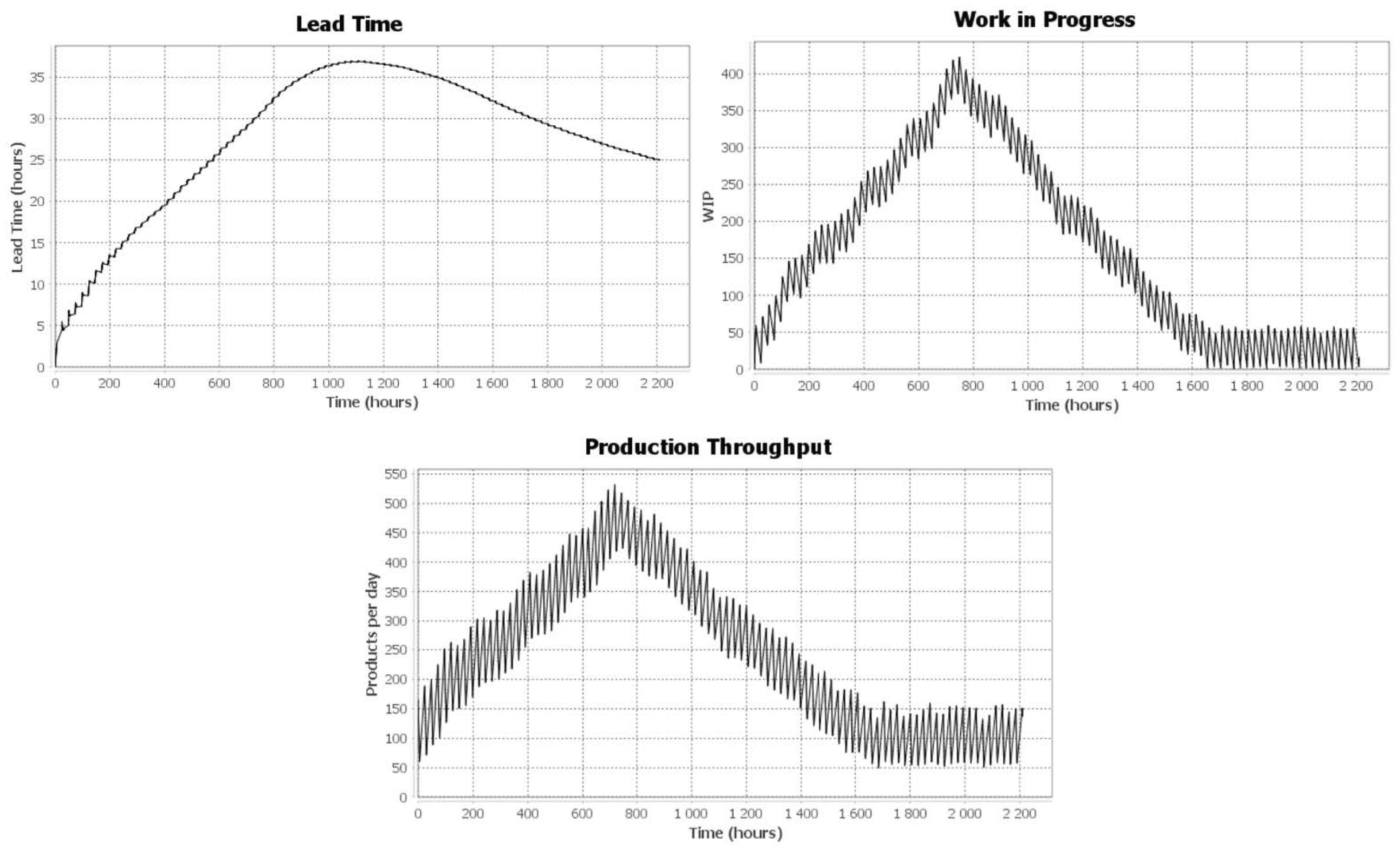
Three KPIs have been configured on the display tool federate to track the production process: lead-time, WIP, and production throughput. These KPIs represent the output results sent from the JaamSim federate to the display tool using the publish/subscribe mechanism of HLA. KPI results are calculated and updated during the simulation run (Figure 16).
The lead time is the time limit for making a product available for consumption once it has been ordered. It includes the time required to place the order, the production process, and the delivery time required to receive the order (checking and unpacking). The second KPI used is the production throughput. The production throughput represents the number of goods produced per day. It is calculated in real-time during the simulation run. It can be affected by various factors such as the planned/unplanned downtime of machines and their reliability, the resource utilization rate, and the distribution of workloads. Throughput optimization, therefore, aims to improve the processing time of the production order and thus increase the overall productivity of the enterprise. The work in progress (WIP) refers to the components awaiting processing, semifinished products, or finished products awaiting production or disposal to stores. It is very important for business managers to keep WIP at minimal levels.
The first simulation scenario simulates the automobile production model without hazard or risk inductions. An order demand that varies from 10 to 100 curves is simulated on DFS. The results are stable, as shown in Figure 17. The lead time is almost 3 h, WIP varies from 1 to maximum 7 goods, and the production throughput varies from 10 to a maximum of 180 cars per day.
Another scenario is launched to test the robustness of the production system while confronting demand increases. At simulation time 20 h, the scenario introduced a demand fluctuation using the developed risk component. This fluctuation represents a 40% demand increase to test the company’s capability of handling such fluctuation. This fluctuation is not configured as a hazardous event from a modeling point of view. However, it is a configured module added to DFS in order for the user to test the demanded fluctuation on the system. From a production perspective, the demand fluctuation cannot be predicted. Thus, it is perceived as an unplanned event that can significantly increase the lead time and WIP of the production system. In this case, the company will be unable to handle such an increase and should search for a solution to meet customer needs.
After the 40% demand increase, one can clearly see that the three KPIs were affected (Figure 17). One can also see that the lead time increased from 5 h at t = 20 h to 30 h at t = 750 h. Additionally, the production throughput increased by almost 300%, and WIP increased by approximately 700% between simulation times t = 20 h and t = 750 h, with a 40% demand increase. At simulation time 750 h, the demand was put back to its initial state. One can see that the results were approximately back to their initial values.
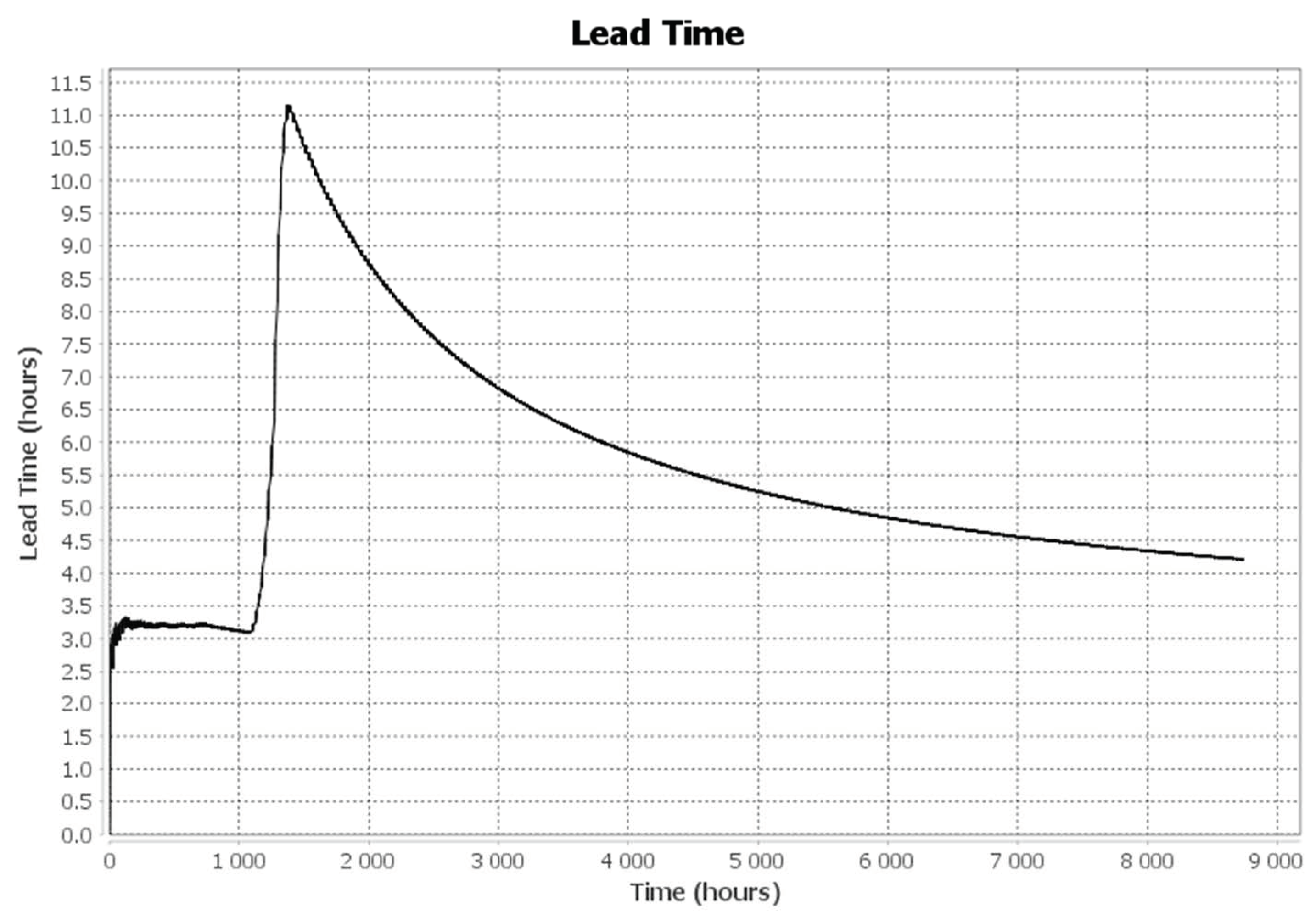
In addition to the demand increase experiment, a delayed raw materials delivery risk was applied, as per Equation (1) of Section 4.2.2 and Figure 18, to analyze how results can be affected by such risks. At t = 1100 h, a risk was induced to DMSF (represented by Hazards_1 in the BPMN model of Figure 16). The risk represents the delayed delivery of each of the finished goods. The production lead time suddenly increased from 3 to 11 h. At t = 1385 h, the simulation was reverted to its risk-free initial state to check enterprise flexibility during such fluctuations.
The experiments are mostly to validate the efficiency of the developed DMSF and not to study a realistic production case. The developed DMSF is considered a decision support tool for managers and engineers to track their production systems—whether it is a solid system that can face hazards and is slightly affected by external disturbances or a system that needs restructuring for more efficiency and reliability to confront hazardous events.
7. Discussion
To situate the contribution of this platform in a more general context, it would be interesting to include a methodology that can collect user requirements, down to models and simulations. Model-driven engineering (MDE) provides techniques and guidelines to create models (i.e., it can require metamodeling to define the model structure) from conceptual models (business models) to system development and/or executable code to be embedded in the systems. In this approach, the models can be transformed into other models (thanks to matching mechanism and code). The model-driven system engineering application (MDSEA) [37] is proposed to specify and consider, regarding MDE, the different views to be represented. The main goal of MDSEA is to model various kinds of systems and support the development of its major components, according to three domains: information technology (IT), human/organization (H/O), and physical means (PM; i.e., machine or any physical tool). One of the originalities of the approach is based on the transformation from one level to another level:
- From the business service model (BSM) level, as the high-level abstraction adapted to the business point of view, to the TIM (technology-independent model) level, as the technical point of view, regardless of the technology choice.
- From the TIM level to the technology-specific model (TSM) level, as the detailed technical level, resulting in the final development of components.
The authors believe that simulation is a mandatory step in the model-driven approach, especially at the TIM level, before launching the development of the cyber and/or physical system. It has been confirmed in recent research works and, in particular, by a study conducted by [38] that any complex system study (design, analysis, or control) cannot be performed without considering simulation-based techniques. The authors stated that a simulation-based approach in any discipline is a rational way to enhance engineering performance effectively. Consequently, in this work, simulation has been used at the TIM level for supply chain system process modeling. Thanks to the simulation results, some behavior predictions and performance analyses regarding hazards affecting the system execution have been studied.
Nevertheless, these results have not performed a detailed analysis of different alternatives since the objective was, first of all, a proof of concept. For example, as a general contribution to engineering design, and according to works done in [39], sensitivity analyses could complement the study, allowing a further look into the interactions between the system and its environment. Furthermore, in the future, virtual prototyping could be proposed by generating animated 3D renderings from simulation results. The planning of production could also be anticipated, thanks to the simulation outlined in this paper. Additionally, as the example considered is a simple use case, the acquisition of data is not discussed, but could potentially provide an interesting perspective.
8. Conclusions and Perspectives
This paper presents a modeling and simulation method and a DMSF platform. This federative platform brings interoperability to several modeling and simulation languages and components. This work expands Papyrus to communicate with new external components through two DS standards. DMSF is now a platform master for distributed simulations made of both HLA and FMU-FMI components. On the one hand, HLA is used to communicate with JaamSim simulations, a display tool, while, on the other hand, FMI is used to communicate with the risk management tool and the Java app. For instance, Papyrus now works with a risk management tool connected with Java Database Connectivity (JDBC) to form the DMSF. Then, as demonstrated, thanks to the Java app, it can be connected to any IoT device through the calls to services outside the platform. As a result, this DMSF platform provides models and simulation to study and evaluate the sustainability of the system. The platform orchestration is hence reconfigurable, thanks to the user-made BPMN model that defines the interactions of different smart manufacturing components and services. Consequently, this work contributes to the improvement of sustainability in smart supply chains and manufacturing factories in their environments. In future works, some statistical tests will be realized to ensure the efficiency and reliability of the proposed method in comparison to other studies. The authors believe that this contribution is an innovative digital M&S platform for manufacturing and supply chains. It anticipates future enterprise design in the frame of Industry 4.0.
Author Contributions
Conceptualization, S.G., J.P., G.Z., Y.D., and N.P.; methodology, S.G., J.P., G.Z., Y.D., and N.P.; software, S.G., J.P., and G.Z.; validation, S.G., J.P., G.Z., and Y.D.; formal analysis, S.G., J.P., G.Z., and Y.D.; investigation, S.G., J.P., G.Z., and Y.D.; resources, S.G., J.P., G.Z., and Y.D.; data curation, S.G. and J.P.; writing—original draft preparation, S.G., J.P., G.Z., and Y.D.; writing—review and editing, S.G., J.P., G.Z., and Y.D.; visualization, S.G. and J.P.; supervision, G.Z. and Y.D.; project administration, G.Z.; funding acquisition, G.Z. and N.P. All authors have read and agreed to the published version of the manuscript.
Funding
This research was partially funded by Region Nouvelle Aquitaine, grant number 2016-1R60102-00007447.
Acknowledgments
Authors acknowledge ALSOLENTECH and CEA TECH for their technical support and their help in using Papyrus and Moka.
Conflicts of Interest
The authors declare no conflict of interest.
References
- Kagermann, H.; Wahlster, W.; Helbig, J. Umsetzungsempfehlungen für das Zukunftsprojekt Industrie 4.0–Deutschlands Zukunft als Industriestandort sichern, Forschungsunion Wirtschaft und Wissenschaft, Arbeitskreis Industrie 4.0; Springer: Berlin/Heidelberg, Germany, 2013. [Google Scholar]
- Adamik, A.; Nowicki, M. Preparedness of companies for digital transformation and creating a competitive advantage in the age of Industry 4.0. In Proceedings of the International Conference on Business Excellence, Sciendo, Lodz, Poland, 1 May 2018; Volume 12, pp. 10–24. [Google Scholar]
- Ericson, Å.; Lugnet, J.; Solvang, W.D.; Kaartinen, H.; Wenngren, J. Challenges of Industry 4.0 in SME businesses. In Proceedings of the 2020 3rd International Symposium on Small-scale Intelligent Manufacturing Systems (SIMS), Gjøvik, Norway, 10–12 June 2020. [Google Scholar]
- Ghadge, A.; Er Kara, M.; Moradlou, H.; Goswami, M. The impact of Industry 4.0 implementation on supply chains. J. Manuf. Technol. Manag. 2020, 31, 669–686. [Google Scholar] [CrossRef]
- Taylor, S.J.E. Distributed simulation: State-of-the-art and potential for operational research. Eur. J. Oper. Res. 2019, 273, 1–19. [Google Scholar] [CrossRef] [Green Version]
- Sun, Y.; Bi, K.; Yin, S. Measuring and Integrating Risk Management into Green Innovation Practices for Green Manufacturing under the Global Value Chain. Sustainability 2020, 12, 545. [Google Scholar] [CrossRef] [Green Version]
- Panetto, H.; Iung, B.; Ivanov, D.; Weichhart, G.; Wang, X. Challenges for the cyber-physical manufacturing enterprises of the future. Annu. Rev. Control. 2019, 47, 200–213. [Google Scholar] [CrossRef]
- Krajewski, L.J.; Malhotra, M.K.; Ritzman, L.P.; Malhotra, M.K.; Ritzman, L.P. Operations Management: Processes and Supply Chains; Pearson: Upper Saddle River, NJ, USA, 2010. [Google Scholar]
- Guermazi, S.; Tatibouet, J.; Cuccuru, A.; Seidewitz, E.; Dhouib, S.; Gérard, S. Executable Modeling with fUML and Alf in Papyrus: Tooling and Experiments. In CEUR Workshop Proceedings (CEUR-WS.org) Vol. 1560, Proceedings of the 1st International Workshop on Executable Modeling co-located with ACM/IEEE 18th International Conference on Model Driven Engineering Languages and Systems (MODELS 2015), Ottawa, ON, Canada, 27 September 2015; Mayerhofer, T., Langer, P., Seidewitz, E., Gray, J., Eds.; 2015; pp. 3–8. [Google Scholar]
- King, D.H.; Harrison, H.S. Open-source simulation software “JaamSim”. In Proceedings of the 2013 Winter Simulations Conference (WSC), Washington, DC, USA, 8–11 December 2013; IEEE: Piscataway, NJ, USA, 2013; pp. 2163–2171. [Google Scholar]
- Dahmann, J.S.; Fujimoto, R.M.; Weatherly, R.M. The DoD high level architecture: An update. In Proceedings of the 1998 Winter Simulation Conference (Cat. No. 98CH36274), Washington, DC, USA, 13–16 December 1998; IEEE: Piscataway, NJ, USA, 1998; Volume 1, pp. 797–804. [Google Scholar]
- Gorecki, S.; Bouanan, Y.; Ribault, J.; Zacharewicz, G.; Perry, N. Including Co-Simulation in modeling and Simulation tool for supporting risk management in industrial context. In Proceedings of the International Multidisciplinary Modeling & Simulation Multiconference, Budapest, Hungary, 17–21 September 2018. [Google Scholar]
- Blochwitz, T. Functional Mock-up Interface for Model Exchange and Co-Simulation. 2016. Available online: https://fmi-standard.org/downloads (accessed on 15 July 2020).
- Saxena, P.; Stavropoulos, P.; Kechagias, J.; Salonitis, K. Sustainability Assessment for Manufacturing Operations. Energies 2020, 13, 2730. [Google Scholar] [CrossRef]
- Konstantas, D.; Bourrières, J.-P.; Léonard, M.; Boudjlida, N. Interoperability of Enterprise Software and Applications; Springer Science & Business Media: Berlin, Germany, 2006; Volume 1, ISBN 1-84628-152-0. [Google Scholar]
- Fujimoto, R.M. Parallel and Distributed Simulation Systems; Wiley: New York, NY, USA, 2000; Volume 300. [Google Scholar]
- Shafiq, S.I.; Sanin, C.; Szczerbicki, E. Knowledge-Based Virtual Modeling and Simulation of Manufacturing Processes for Industry 4.0. Cybern. Syst. 2020, 51, 84–102. [Google Scholar] [CrossRef]
- Bazoun, H.; Zacharewicz, G.; Ducq, Y.; Boyé, H. SLMToolBox: An Implementation of MDSEA for Servitisation and Enterprise Interoperability. In Enterprise Interoperability VI; Mertins, K., Bénaben, F., Poler, R., Bourrières, J.-P., Eds.; Springer International Publishing: Cham, Switzerland, 2014; pp. 101–111. [Google Scholar]
- IDEAS Consortium. Thematic Network, IDEAS Interoperability Development for Enterprise Application and Software Roadmaps; IDEAS Tech Report Annex. 2002. Available online: http://interop-vlab.eu/ideas/ (accessed on 25 August 2020).
- Chen, D.; Dassisti, M.; Elvesæter, B. Enterprise Interoperability Framework and Knowledge Corpus-Final Report Annex: Knowledge Pieces; Contract No IST508; 2007; Volume 11, Available online: http://interop-vlab.eu/interop/ (accessed on 25 August 2020).
- Singhal, S.; Zyda, M. Networked Virtual Environments: Design and Implementation; Addison-Wesley: Boston, MA, USA, 1999. [Google Scholar]
- Taylor, S.J.E.; Bruzzone, A.; Fujimoto, R.; Gan, B.P.; Strassburger, S.; Paul, R.J. Distributed simulation and industry: Potentials and pitfalls. In Proceedings of the Winter Simulation Conference, San Diego, CA, USA, 8–11 December 2002; IEEE: Piscataway, NJ, USA, 2002; 1, pp. 688–694. [Google Scholar]
- Possik, J.; Amrani, A.; Zacharewicz, G. WIP: Co-simulation system serving the configuration of lean tools for a manufacturing assembly line. In Proceedings of the Works in Progress Symposium, WIP 2018, Part of the 2018 Spring Simulation Multiconference, Baltimore, MD, USA, 15 November 2018. [Google Scholar]
- Waller, A.P.; Ladbrook, J. Experiencing virtual factories of the future. In Proceedings of the Winter Simulation Conference; San Diego, CA, USA, 8–11 December 2002, IEEE: Piscataway, NJ, USA, 2002; Volume 1, pp. 513–517. [Google Scholar]
- Possik, J.J.; Amrani, A.A.; Zacharewicz, G. Development of a co-simulation system as a decision-aid in Lean tools implementation. In Proceedings of the 50th Computer Simulation Conference, Bordeaux, France, 9–12 July 2018; p. 21. [Google Scholar]
- Cleary, P.W.; Thomas, D.; Hetherton, L.; Bolger, M.; Hilton, J.E.; Watkins, D. Workspace: A workflow platform for supporting development and deployment of modelling and simulation. Math. Comput. Simul. 2020, 175, 25–61. [Google Scholar] [CrossRef]
- Zacharewicz, G.; Frydman, C.; Giambiasi, N. G-DEVS/HLA environment for distributed simulations of workflows. Simulation 2008, 84, 197–213. [Google Scholar] [CrossRef] [Green Version]
- Van Der Aalst, W.; Van Hee, K.M.; van Hee, K. Workflow Management: Models, Methods, and Systems; MIT Press: Cambridge, MA, USA, 2004. [Google Scholar]
- Tiacci, L. Object-oriented event-graph modeling formalism to simulate manufacturing systems in the Industry 4.0 era. Simul. Model. Pract. Theory 2020, 99, 102027. [Google Scholar] [CrossRef]
- Bastian, J.; Clauß, C.; Wolf, S.; Schneider, P. Master for Co-Simulation Using FMI. In Proceedings of the 8th International Modelica Conference, Dresden, Germany, 20–22 March 2011; pp. 115–120. [Google Scholar]
- Sievert, N. Modelica Models in a Distributed Environment Using FMI and HLA. Master’s Thesis, Linköping University, Linköping, Sweden, 2016. [Google Scholar]
- Gorecki, S.; Ribault, J.; Zacharewicz, G.; Ducq, Y.; Perry, N. Risk management and distributed simulation in Papyrus tool for decision making in industrial context. Comput. Ind. Eng. 2019, 137, 106039. [Google Scholar] [CrossRef]
- Kadir, Z.A.; Mohammad, R.; Othman, N.; Amrin, A.; Muhtazaruddin, M.N.; Abu-Bakar, S.H.; Muhammad-Sukki, F. Risk Management Framework for Handling and Storage of Cargo at Major Ports in Malaysia towards Port Sustainability. Sustainability 2020, 12, 516. [Google Scholar] [CrossRef] [Green Version]
- Gorecki, S.; Bouanan, Y.; Zacharewicz, G.; Perry, N. BPMN Modeling for hla based simulation and visualization. In Proceedings of the Society for Modeling and Simulation—SpringSim-Mod4Sim 2018, Baltimore, MD, USA, 15–18 April 2018; pp. 1–12. [Google Scholar]
- IEEE Computer Society 1516.2-2010—IEEE Standard for Modeling and Simulation (M&S) High Level Architecture (HLA)—Object Model Template (OMT) Specification; IEEE Computer Society: Washington, DC, USA, 2010.
- Automotive Industry|History, Developments, & Facts. Available online: https://www.britannica.com/technology/automotive-industry (accessed on 4 August 2020).
- D’Ambrogio, A.; Zacharewicz, G. Report of Collaborative Modeling and Simulation (CoMetS) Track of WETICE 2019. In Proceedings of the 2019 IEEE 28th International Conference on Enabling Technologies: Infrastructure for Collaborative Enterprises (WETICE), Napoli, Italy, 12–14 June 2019; pp. 104–105. [Google Scholar]
- Mittal, S.; Durak, U.; Ören, T. Guide to Simulation-Based Disciplines: Advancing Our Computational Future; Springer: Berlin/Heidelberg, Germany, 2017. [Google Scholar]
- Possik, J.; D’Ambrogio, A.; Zacharewicz, G.; Amrani, A.; Vallespir, B. A BPMN/HLA-Based Methodology for Collaborative Distributed DES. In Proceedings of the 2019 IEEE 28th International Conference on Enabling Technologies: Infrastructure for Collaborative Enterprises (WETICE), Napoli, Italy, 12–14 June 2019; pp. 118–123. [Google Scholar]
Figure 1.
The nonstandardized approach to addressing system interoperability: (a) decentralized; (b) centralized.
Figure 1.
The nonstandardized approach to addressing system interoperability: (a) decentralized; (b) centralized.

Figure 2.
Conceptual design.

Figure 3.
Distributed simulation framework.

Figure 4.
Papyrus-layer architecture.

Figure 5.
Model transformation from Papyrus to InfluxDB.

Figure 6.
Advice and visitors associated with UML models by the Moka execution engine.

Figure 7.
BPMN (business process model and notation) of Papyrus and risk management modules.

Figure 8.
Papyrus/risk management time management.

Figure 9.
Triggering new risks from events.

Figure 10.
JaamSim HLA time management process.

Figure 11.
High-level architecture (HLA) implementation model and timeline.

Figure 12.
HLA federation object model (FOM) structure.

Figure 13.
Moka unified modeling language (UML) profile.

Figure 14.
Functional mock-up unit (FMU) for the cosimulation model.

Figure 15.
HLA time management process.

Figure 16.
Simulation results with no risks or hazards.

Figure 17.
Simulation results affected by a 40% demand increase.

Figure 18.
Lead time results affected by raw material delivery delay risk.

© 2020 by the authors. Licensee MDPI, Basel, Switzerland. This article is an open access article distributed under the terms and conditions of the Creative Commons Attribution (CC BY) license (http://creativecommons.org/licenses/by/4.0/).
Share and Cite
MDPI and ACS Style
Gorecki, S.; Possik, J.; Zacharewicz, G.; Ducq, Y.; Perry, N. A Multicomponent Distributed Framework for Smart Production System Modeling and Simulation. Sustainability 2020, 12, 6969. https://0-doi-org.brum.beds.ac.uk/10.3390/su12176969
AMA Style
Gorecki S, Possik J, Zacharewicz G, Ducq Y, Perry N. A Multicomponent Distributed Framework for Smart Production System Modeling and Simulation. Sustainability. 2020; 12(17):6969. https://0-doi-org.brum.beds.ac.uk/10.3390/su12176969
Chicago/Turabian StyleGorecki, Simon, Jalal Possik, Gregory Zacharewicz, Yves Ducq, and Nicolas Perry. 2020. "A Multicomponent Distributed Framework for Smart Production System Modeling and Simulation" Sustainability 12, no. 17: 6969. https://0-doi-org.brum.beds.ac.uk/10.3390/su12176969
Note that from the first issue of 2016, this journal uses article numbers instead of page numbers. See further details here.