
Research and Practice on Filling Technology of Fully Mechanized Coal Mining Face through Trend Abandoned Roadway

Abstract
:1. Introduction
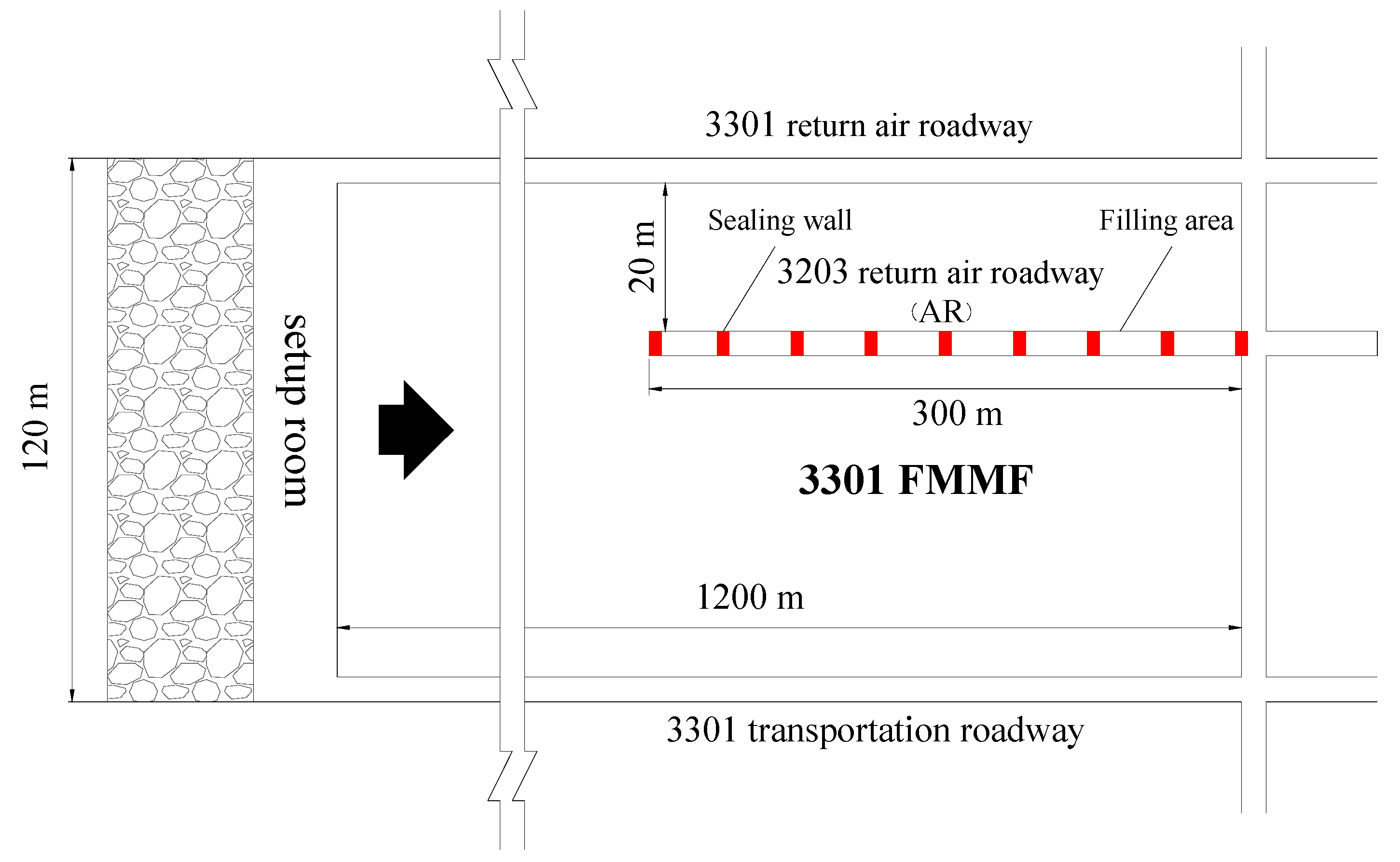
2. Engineering Background
3. Study on Roof Instability Mechanism of AR
3.1. Stress Distribution Law of Surrounding Rock with AR
3.2. Deformation and Failure Characteristics of Surrounding Rock with AR
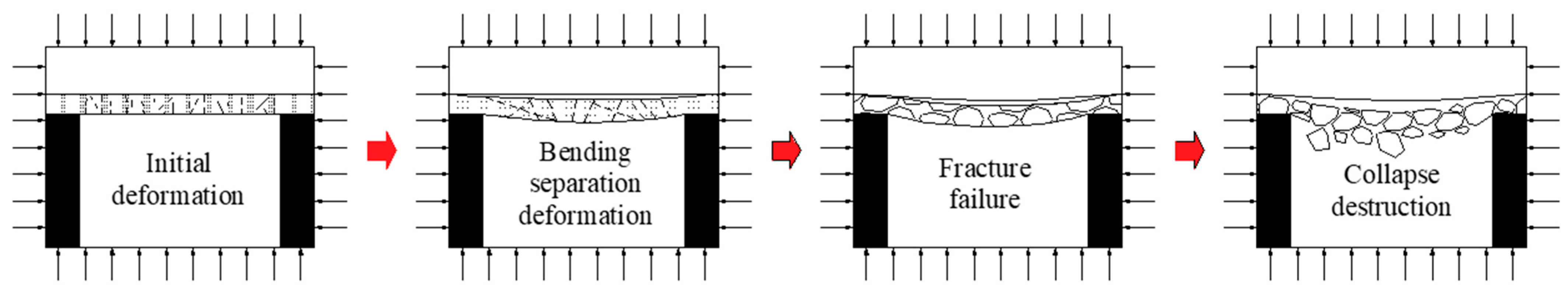
3.3. Roof of AR Deformation and Failure Deduction
- (1)
- Initial deformation. The span of the immediate roof rock is enlarged and the deformation occurs due to the influence of the overburden pressure after the tunneling of AR. The results show that the deformation of rock strata is basically perpendicular to the normal direction of the bedding plane, and the fissures of surrounding rock gradually develop into joint fissure group with the tunneling of AR;
- (2)
- Bending separation deformation. With the advance of the working face, the overlying rock of the upper part of the AR appears deflection, and the vertical asynchronous movement between the immediate roof and the basic roof forms longitudinal separation, resulting in bed separation;
- (3)
- Fracture failure. With the increase of disturbance degree, the amount of separation layer increases gradually, the cohesion between layers is lost, the deflection of immediate roof layer increases rapidly, and the fracture failure begins;
- (4)
- Collapse destruction. Under the action of mining stress, the immediate roof is rapidly transformed from fracture to collapse with the work facing the AR. If it is not supported in time, it will directly threaten the safety of equipment and personnel.
4. Determination of FMMR through the Trend AR
4.1. Technical Perspective
4.2. Economic Perspective
- (1)
- The support is strengthened by dense pillars or wooden stacks. 3301 FMMF through the AR, each coal cutting cycle requires the removal of dense pillars or wooden stacks, the process needs to stop for 20 min, a total of 120 min a day, which is equivalent to cutting a knife less coal per shift. It takes two months for the FMMF through the AR, and the economic loss is not less than 1.2 million RMB;
- (2)
- The FMMF moves around the AR. 3301 FMMF moved for at least 15 days, during which a large amount of coal resources were less exploited, and the economic loss was not less than 2 million RMB;
- (3)
- High water material filling. The filling space of the AR is 1800 m3. According to the water cement ratio of 8:1, 160 tons of high water materials are needed, and the cost of filling materials is 368,000 RMB, the purchase of special filling equipment is about 200,000 yuan, and the total cost is no more than 600,000 RMB.
5. Determination of Key Parameters for Backfill
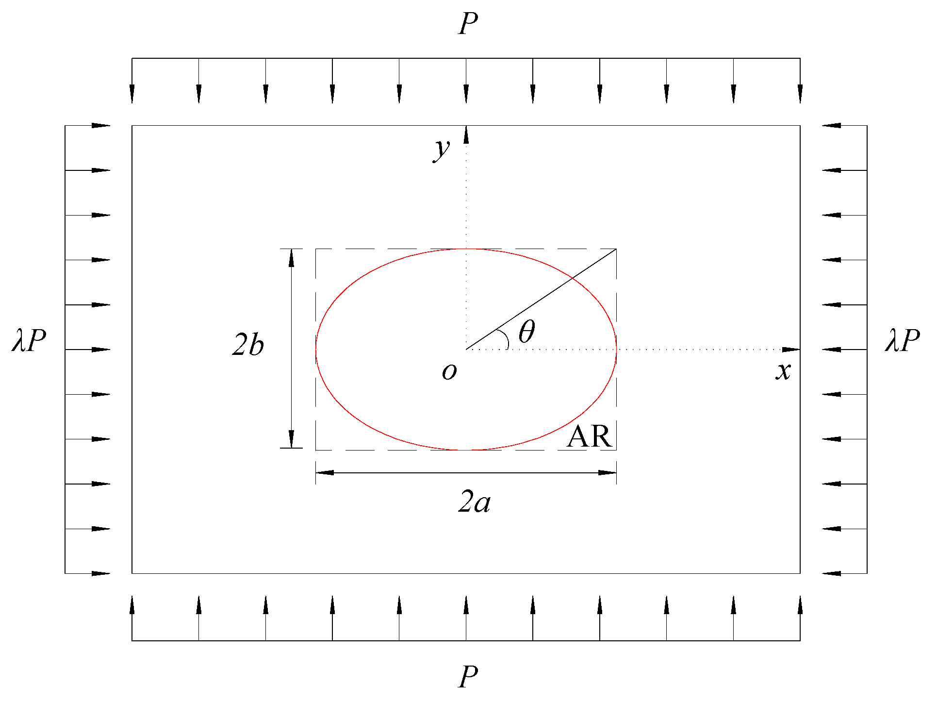
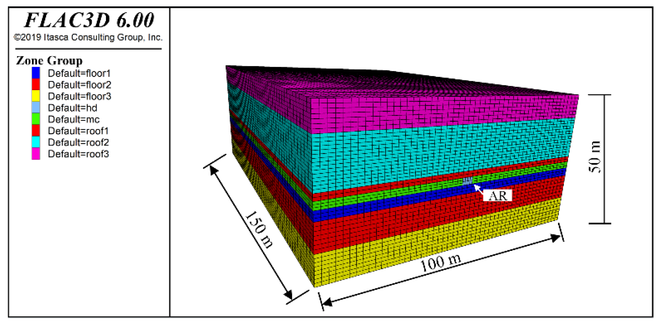
5.1. The Establishment of the Model
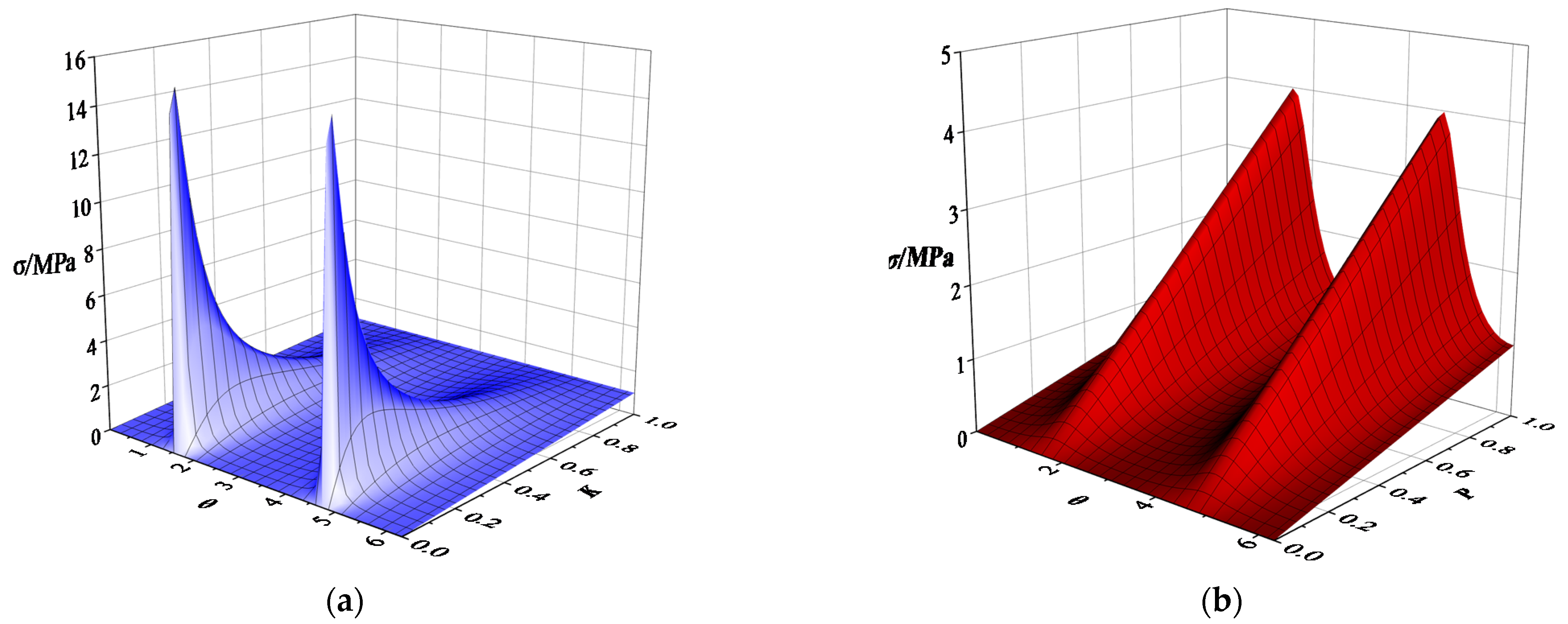
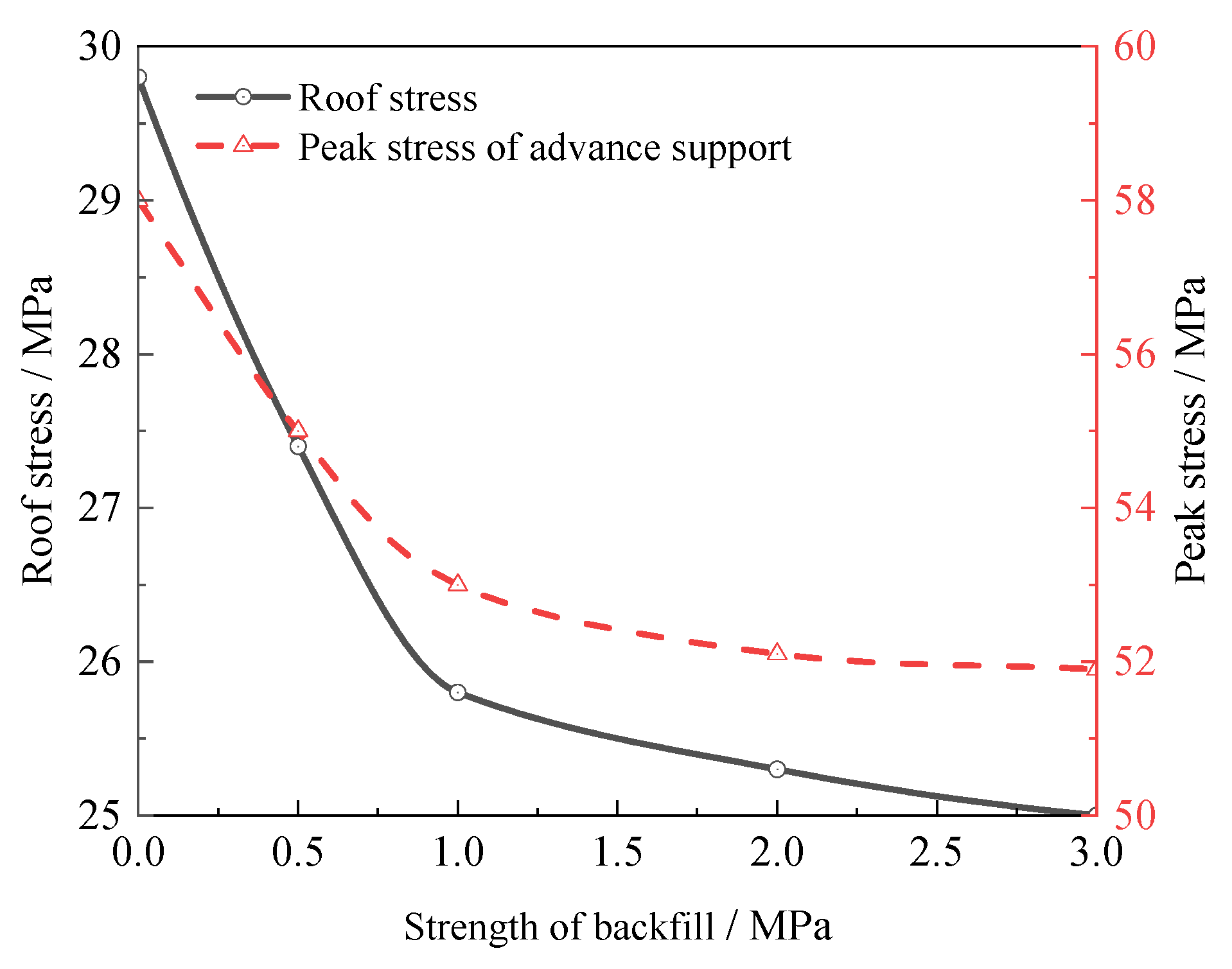
5.2. Stress Distribution Characteristics of Surrounding Rock with AR
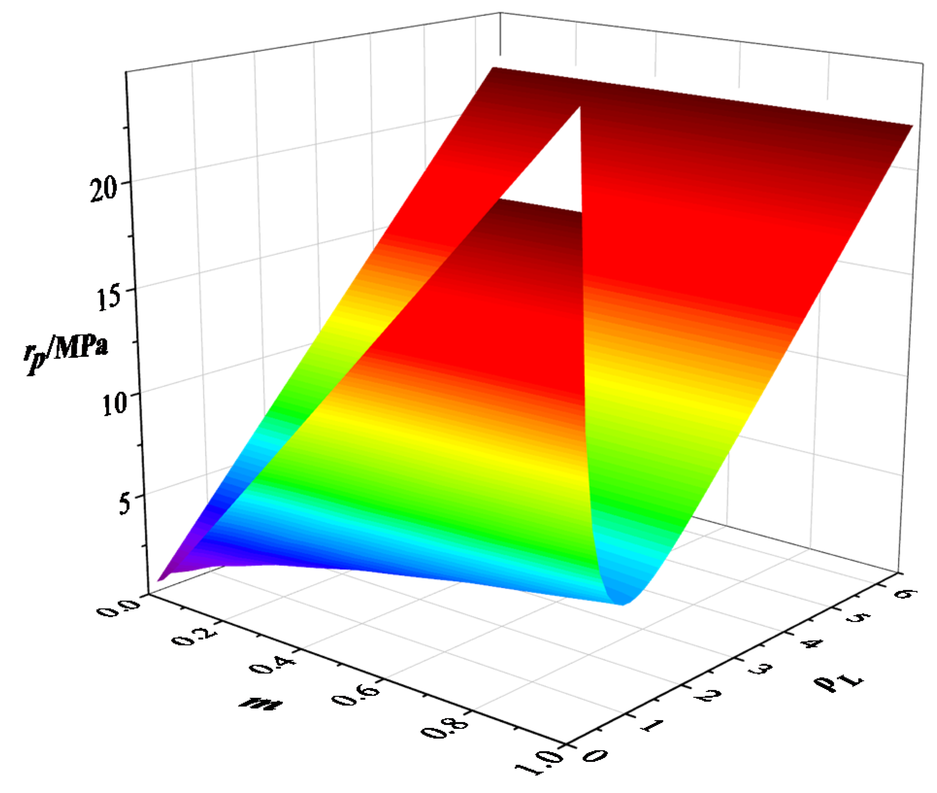
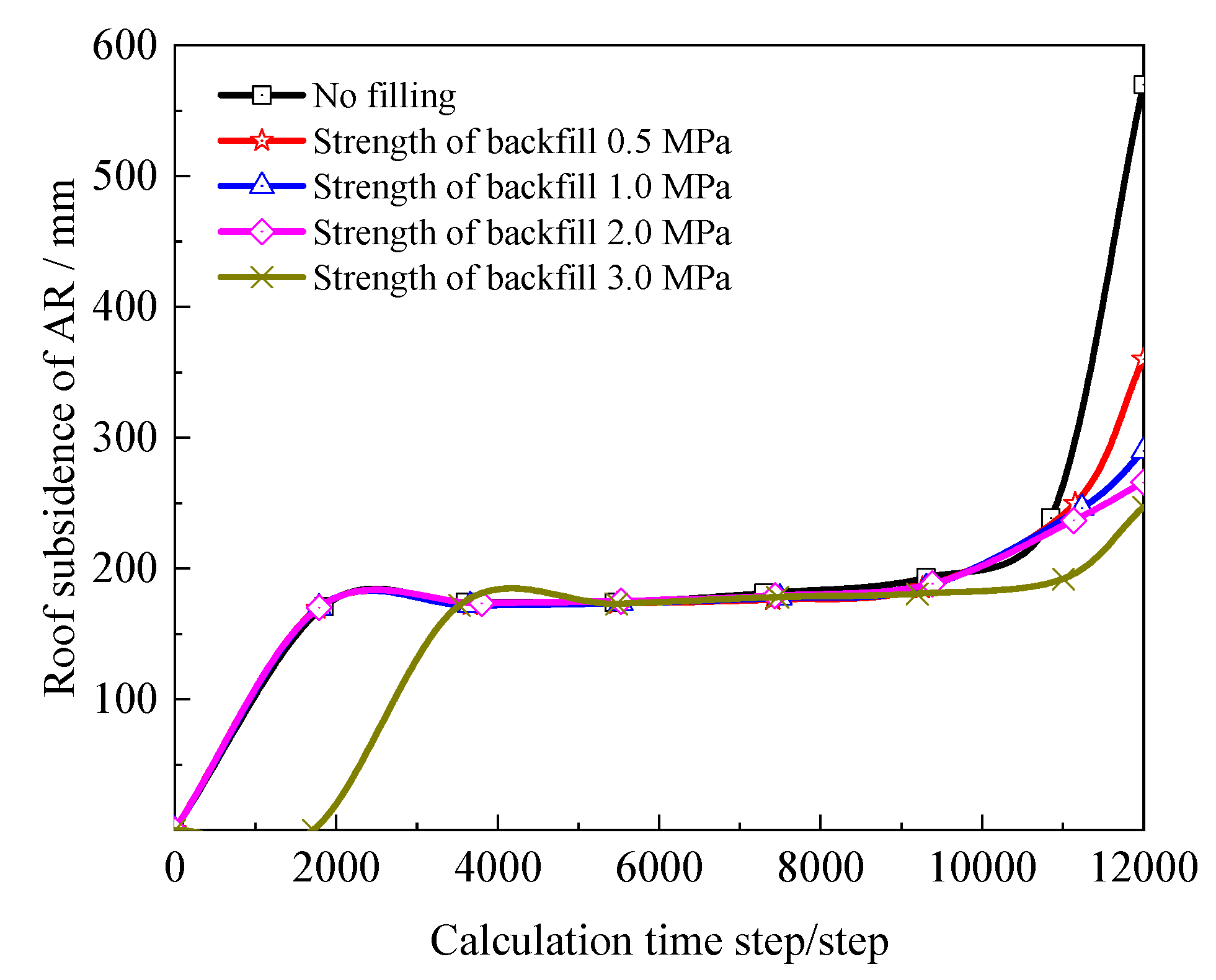
5.3. Deformation Characteristics of Surrounding Rock with AR
6. Industrial Test
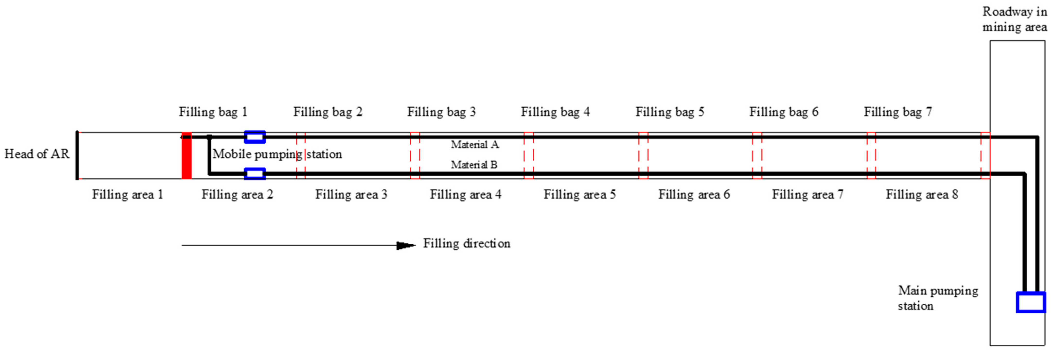
6.1. Filling Scheme
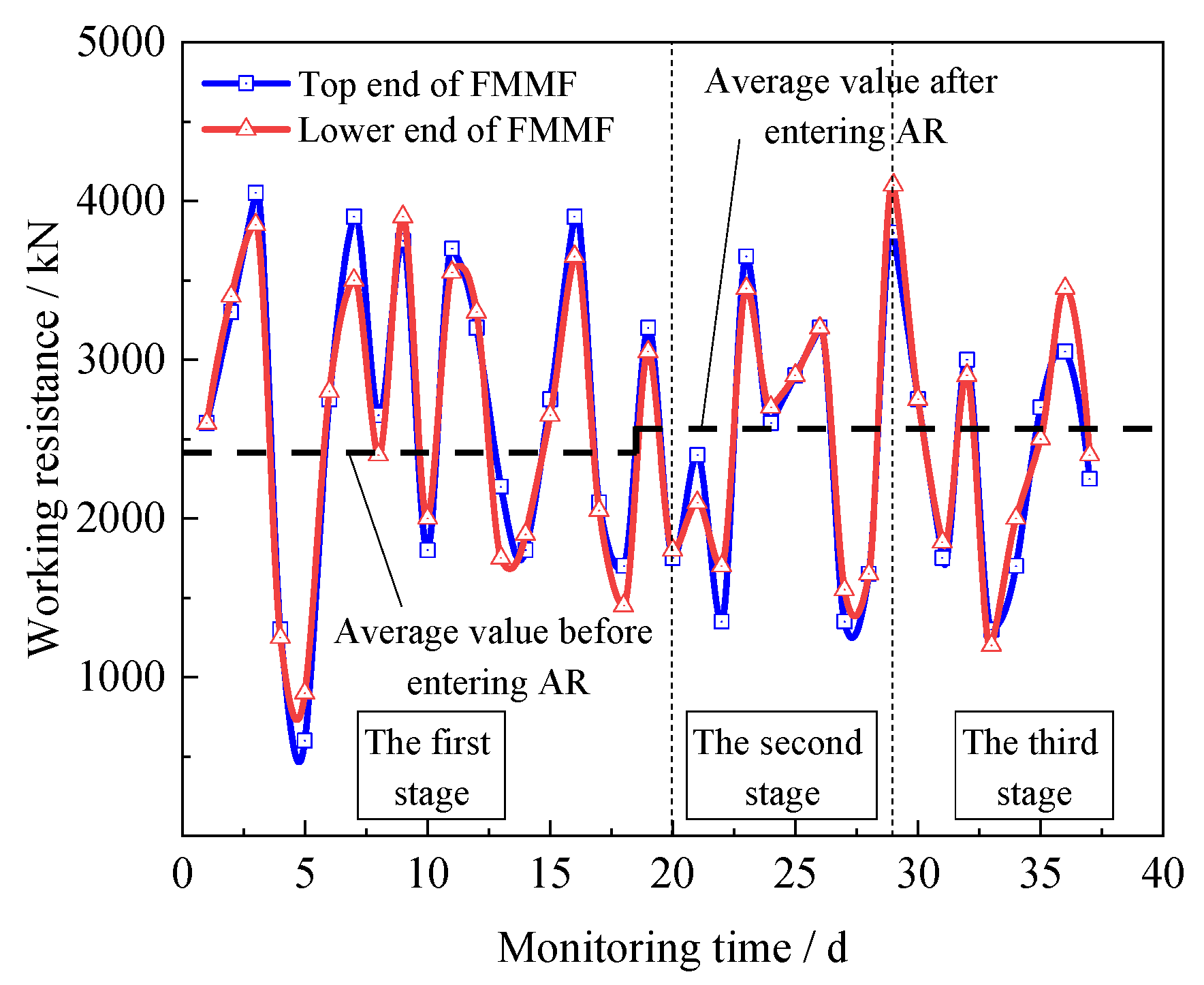
6.2. Filling Effect
7. Conclusions
- (1)
- Through theoretical calculation, the instability mechanism of surrounding rock with AR is studied, and it is determined that the ratio of height to span is the key factor affecting the stability of surrounding rock with AR. The four stages of deformation and failure evolution of with AR roof are deduced: initial deformation, bending and separation deformation, fracture failure, and collapse destruction. It is proposed that the control principle of timely support and reducing roof span should be followed for controlling surrounding rock strata of AR.
- (2)
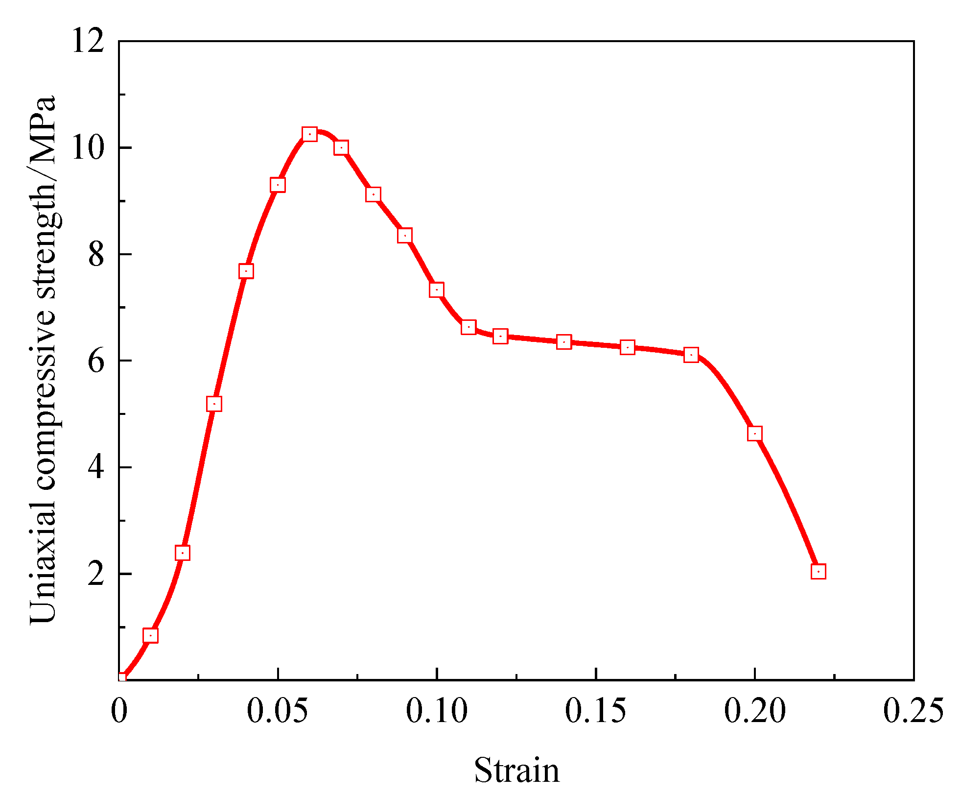
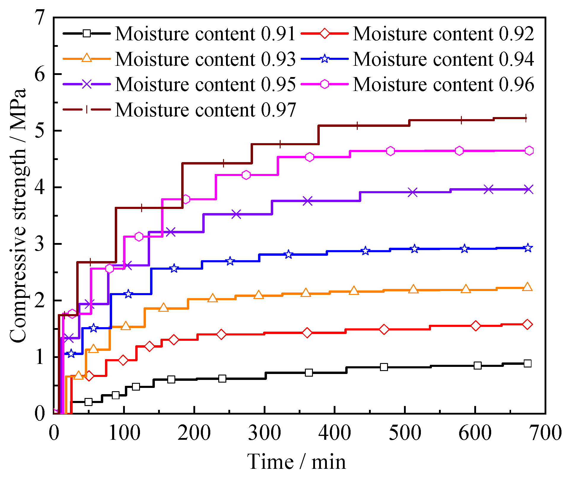
- By comparing the traditional way of FMMF through the AR and considering the technical and economic factors, it is proposed the use of high water materials to fill the AR roof control technology. The mechanism of the filling body and the surrounding rock of the AR is researched, and the key parameters of the filling body are determined. The strength of the filling body is 1.0 MPa, and the water cement ratio of the corresponding high water material is 8:1.
- (3)
- The industrial test shows that the average working resistance increment of hydraulic support does not exceed 150 kN before and after the FMMF through the AR, and the roof subsidence of the AR is small, which ensures the safe promotion of the FMMF, and the effect of filling and controlling the roof is good.
Author Contributions
Funding
Acknowledgments
Conflicts of Interest
References
- Hornborg, A. Ecological economics, Marxism, and technological progress: Some explorations of the conceptual foundations of theories of ecologically unequal exchange. Ecol. Econ. 2014, 105, 11–18. [Google Scholar] [CrossRef]
- Wu, R.L.; Liu, F.; Tong, D.; Zheng, Y.X.; Lei, Y.; Hong, C.P.; Li, M.; Liu, J.; Zheng, B.; Bo, Y.; et al. Air quality and health benefits of China’s emission control policies on coal-fired power plants during 2005–2020. Environ. Res. Lett. 2019, 14, 094016. [Google Scholar] [CrossRef]
- Zhang, W.H.; Yan, Q.Y.; Yuan, J.H.; He, G.; Teng, T.L.; Zhang, M.J.; Zeng, Y. A realistic pathway for coal-fired power in China from 2020 to 2030. J. Clean. Prod. 2020, 275, 122859. [Google Scholar] [CrossRef]
- Du, Y.L.; Feng, G.R.; Zhang, Y.J.; Zhang, X.H.; Zhai, Y.D.; Bai, J.W. Pressure reduction mechanism and effect of working face passing through abandoned roadway by roof presplit. Energy Sci. Eng. 2020, 8, 3502–3513. [Google Scholar] [CrossRef]
- Li, Y.; Lei, M.X.; Wang, H.S.; Li, C.; Li, W.W.; Tao, Y.; Wang, J.Y. Abutment pressure distribution for longwall face mining through abandoned roadways. Int. J. Min. Sci. Technol. 2019, 29, 59–64. [Google Scholar] [CrossRef]
- Zhang, X.Q.; Gong, P.L.; Wang, K.; Li, J.Z.; Jiang, Y.L. Characteristic and Mechanism of Roof Fracture Ahead of the Face in an LTCC Panel When Passing an Abandoned Roadway: A Case Study from the Shenghua Coal Mine, China. Rock Mech. Rock Eng. 2019, 52, 2775–2788. [Google Scholar] [CrossRef]
- Yang, Z.Q.; Liu, C.; Wang, G.A.; Li, G.W.; Li, F.S. Structural Characteristics Analysis of Overlying Rocks and Prevention Measures with a Long-Wall Face Passing across Abandoned Roadways: A Case Study. Shock Vib. 2021, 2021, 665341. [Google Scholar] [CrossRef]
- Liu, Z.H.; Ye, H.L.; Yang, L.S.; Wang, S.H.; Zhang, J.W.; Zhang, B.S.; Li, Z.Q. Study on Control Technology for Working Faces Passing through Long-Span Abandoned Roadways. Geofluids 2020, 2020, 8822595. [Google Scholar] [CrossRef]
- Ma, W.Q.; Wang, T.X. Instability Mechanism and Control Countermeasure of a Cataclastic Roadway Regenerated Roof in the Extraction of the Remaining Mineral Resources: A Case Study. Rock Mech. Rock Eng. 2019, 52, 2437–2457. [Google Scholar] [CrossRef]
- Bai, J.-B.; Hou, C.-J. Research on principle of roof stability of abandoned workings and supporting technology. Meitan Xuebao/J. China Coal Soc. 2005, 30, 8–11. [Google Scholar]
- Liu, C.; Gong, P.-L.; Wang, K.; Zhang, X.-Q.; Liu, Y.-D. Roof stability for repeated mining workface passing through abandoned parallel gateway. Meitan Xuebao/J. China Coal Soc. 2015, 40, 314–322. [Google Scholar] [CrossRef]
- Xie, S.-R.; Li, S.-J.; Wei, Z.; Sun, Y.-J.; Zhang, G.-C.; Song, B.-H.; He, F.-L.; Tian, C.-Y. Stability control of support-surrounding rock system during fully mechanized caving face crossing abandoned roadway period. Meitan Xuebao/J. China Coal Soc. 2015, 40, 502–508. [Google Scholar] [CrossRef]
- Yin, C.; Feng, G.; Gao, P.; Zhao, Y. Research on instability mechanism of surrounding rock in stage of working face passing abandoned roadway. Caikuang Yu Anquan Gongcheng Xuebao/J. Min. Saf. Eng. 2018, 35, 457–464. [Google Scholar] [CrossRef]
- Xu, Q.; Ning, Z.; Zhu, R.; Zeng, K. Study on instability mechanism and top controlof overfilled roof in fully mechanizedcaving face. Caikuang Yu Anquan Gongcheng Xuebao/J. Min. Saf. Eng. 2019, 36, 505–512. [Google Scholar] [CrossRef]
- Fujii, Y.; Sugawara, T.; Kodama, J.; Ishijima, Y.; Kiyama, T.; Takada, M.; Ichihara, Y.; Kumakura, S.; Narita, T.; Sawada, M.; et al. Abandoned Roadways Aged up to 50 Years Observed in Kushiro Coal Mine, Japan. In Proceedings of the 12th ISRM Congress, Beijing, China, 16–21 October 2011. [Google Scholar]
- Liu, C.; Yang, Z.Q.; Gong, P.L.; Wang, K.; Zhang, X.Q.; Zhang, J.W.; Li, Y.L. Accident Analysis in Relation to Main Roof Structure When Longwall Face Advances toward a Roadway: A Case Study. Adv. Civ. Eng. 2018, 2018, 3810315. [Google Scholar] [CrossRef] [Green Version]
- Sullivan, B.; Tran, K.T.; Logston, B. Characterization of Abandoned Mine Voids Under Roadway with Land-Streamer Seismic Waves. Transp. Res. Rec. 2016, 2580, 71–79. [Google Scholar] [CrossRef]
- Wang, F.T.; Duan, C.H.; Tu, S.H.; Liang, N.N.; Bai, Q.S. Hydraulic support crushed mechanism for the shallow seam mining face under the roadway pillars of room mining goaf. Int. J. Min. Sci. Technol. 2017, 27, 853–860. [Google Scholar] [CrossRef]
- Essen, K.; Bohlen, T.; Friederichl, W.; Meier, T. Modelling of Rayleigh-type seam waves in disturbed coal seams and around a coal mine roadway. Geophys. J. Int. 2007, 170, 511–526. [Google Scholar] [CrossRef] [Green Version]
- Islam, M.N.; Gnanendran, C.T. Elastic-Viscoplastic Model for Clays: Development, Validation, and Application. J. Eng. Mech. 2017, 143, 04017121. [Google Scholar] [CrossRef] [Green Version]
- Tai, Y.; Xia, H.C.; Liu, H.J.; Ma, Z.Y.; Zhang, Y.Q. Control for the large section roadway under small abandoned mines in the same coal seam by secondary support. Energy Sci. Eng. 2020, 8, 3476–3489. [Google Scholar] [CrossRef]


| Sketch | Lithology | Thickness (m) | Basic Description |
|---|---|---|---|
 | false roof shale | 0.45 | Broken, with charcoal grain. |
| immediate roof sand shale | 1.65 | The hardness coefficient is 4.0 and there are many layers. | |
| basic roof sandstone | 5.68 | It is grayish white and contains more quartz. | |
| immediate floor sand shale | 3.70 | The hardness coefficient is 3.0, gray black. | |
| basic floor sandstone | 11.46 | It has a high degree of carbonization and contains plant fossils. |
| Stratum Name | Thickness (m) | Density (kg·m−3) | Bulk Modulus (GPa) | Shear Modulus (GPa) | Cohesion (MPa) | Internal Friction Angle (°) | Tensile Strength (MPa) |
|---|---|---|---|---|---|---|---|
| Overlying strata | 50 | 2450 | 1.02 | 0.46 | 1.9 | 36 | 1.4 |
| Sandstone | 1.0 | 2250 | 3.02 | 1.58 | 1.3 | 28 | 1.1 |
| Sand shale | 2.0 | 2680 | 4.65 | 2.76 | 1.8 | 33 | 2.0 |
| Shale | 6.0 | 2450 | 3.45 | 1.85 | 1.6 | 29 | 1.2 |
| Coal seam | 2.0 | 1450 | 1.20 | 0.37 | 0.8 | 23 | 0.6 |
| Sand shale | 4.0 | 2680 | 4.65 | 2.76 | 1.8 | 33 | 2.0 |
| Sandstone | 11 | 2250 | 3.02 | 1.58 | 1.3 | 28 | 1.1 |
| Program | Water Cement Ratio | Moisture Content | Compressive Strength (MPa) |
|---|---|---|---|
| 1 | 11:1 | 0.97 | 0.5 |
| 2 | 8:1 | 0.96 | 1.0 |
| 3 | 6:1 | 0.95 | 2.0 |
| 4 | 5:1 | 0.94 | 3.0 |
Publisher’s Note: MDPI stays neutral with regard to jurisdictional claims in published maps and institutional affiliations. |
© 2021 by the authors. Licensee MDPI, Basel, Switzerland. This article is an open access article distributed under the terms and conditions of the Creative Commons Attribution (CC BY) license (https://creativecommons.org/licenses/by/4.0/).
Share and Cite
Yu, Y.; Lu, J.; Pan, Y.; Zhao, X.; Chen, D. Research and Practice on Filling Technology of Fully Mechanized Coal Mining Face through Trend Abandoned Roadway. Sustainability 2021, 13, 9920. https://0-doi-org.brum.beds.ac.uk/10.3390/su13179920
Yu Y, Lu J, Pan Y, Zhao X, Chen D. Research and Practice on Filling Technology of Fully Mechanized Coal Mining Face through Trend Abandoned Roadway. Sustainability. 2021; 13(17):9920. https://0-doi-org.brum.beds.ac.uk/10.3390/su13179920
Chicago/Turabian StyleYu, Yang, Jianfei Lu, Yuxin Pan, Xiangqian Zhao, and Dingchao Chen. 2021. "Research and Practice on Filling Technology of Fully Mechanized Coal Mining Face through Trend Abandoned Roadway" Sustainability 13, no. 17: 9920. https://0-doi-org.brum.beds.ac.uk/10.3390/su13179920