
Evolution of Standardized Specifications on Materials, Manufacturing and In-Service Inspection of Nuclear Reactor Vessels

 ,
,  ,
, 


Abstract
:1. Introduction
2. Methodology
2.1. Phase A—Analysis of the Technological Literature on Design and Manufacturing of Critical Mechanical Components
2.1.1. Nuclear Installations: Main Mechanical Components
- The RPV
- The pressurizer (in PWR plants)
- The steam generator (in PWR plants)
- The main coolant pumps
- The pipes that carry the coolant
2.1.2. The RPV. Components: Materials and Manufacturing Processes
- (a)
- Required materials
- Adequate mechanical properties, such as tensile strength, ductility at working temperatures and good creep behavior.
- High thermal conductivity. To favor the elimination of heat from the core and to avoid the generation of internal stresses due to thermal fluxes with an anisotropic profile with respect to heat conduction.
- High resistance to thermal distortion. Due to the thickness of the walls of the pressure vessels, thermal stresses arise as a consequence of the temperature gradient along the thickness of the wall. A high value of the thermal stress is compensated, partially, by a high tensile strength.
- Low coefficient of linear expansion, or where appropriate, with a modulus similar to that of other materials. To avoid the generation of tensions between different components.
- Resistance to corrosion and compatibility with the other components of the reactor with which it must be in contact. The corrosion of the reactor materials, in addition to the associated consequences, such as loss of thickness, formation of cracks, etc., entails that the corrosion products are strongly radioactive and are carried by the coolant towards the outside of the reactor. The carbon steel used in the manufacture of the vessel is highly susceptible to corrosion due to the coolant in the primary circuit, so they cannot be in contact. This corrosion problem is solved by cladding the inside of the vessel with a thin layer of stainless steel. Protection by coatings in this manner is based on the so-called barrier technique, that is, placing an austenitic steel between the medium and the material to be protected that prevents the access of aggressive products from the environment to the material liable to be corroded. The choice of a specific coating depends on the nature of the material to be protected and the aggressiveness of the environment to which it is subjected. It is common to use grades according to the designation AISI 347 or AISI 308L because they do not precipitate chromium carbides at high temperatures. Another advantage of these materials is their weldability with Cr-Mo based materials. For the application in PWR type reactor vessels, the use of type 308L is recommended since it does not precipitate Chromium carbides at high temperature due to its low carbon content and because it presents an austenitic structure with a percentage around 6% ferrite, thus reducing hot cracking compared to AISI 347 steel, since the latter has an austenitic structure [26] which increases the risk of microcracks when conditions could include high temperatures (as when the material is welded or, in operation, in case of abnormal conditions), according to scientific studies have shown such as those published by Moorhead et al. [27] or Cui et al. [28]. Although carbon and low-alloy steels cladded with an austenitic alloy are used in the components of the primary reactor cooling circuit, in some cases, either as a result of repair or due to the existence of defects in the cladding, the base material is exposed to the cooling medium of the primary circuit. For this reason, it is vitally important to monitor the RPV’s mechanical properties, taking into account the possible contact of the carbon steel of the envelope with the reactor coolant, which may lead to boric acid corrosion [29].
- Ease of machining and weldability. A high machinability and adequate weldability are essential to correctly choose a material for the manufacture of an RPV [23]. Thus, usually the required C wt.% is lower than 0.15%.
- Adequate nuclear properties. In the RPV material located near the reactor core, an important aspect to consider in the selection of materials is how they influence the core physics and neutronics; for example, the material should have a small neutron capture cross section. It must be resistant to embrittlement as a result of irradiation and must have low induced radioactivity (from this point of view, the use of ferritic steels as base material is preferable to the more common austenitic steels).
- (b)
- Manufacturing processes
2.1.3. Historical Overview of Technical Codes and Regulations
- Design and manufacturing code: Technical document, which clearly and concisely collects the rules and steps to be followed by the designer who is designing and manufacturing a specific structure or industrial good.
- Technical standard or specification: A technical standard is a specification of repetitive or continuous application whose observance is not mandatory except when a regulation or contract so determines. It is established with the participation of all interested stakeholders, which is approved by a recognized body, nationally or internationally. That is to say, this norm has a device character and not obligatory as it has a legal norm. Therefore, it is a technical document, issued by a standardization body, in which a set of conditions that a material, product or procedure must meet is specified.
- First: referred to constitutional level and International treaties or agreements.
- Second: statutory level, at which specific laws are enacted by a parliament in order to establish other necessary bodies and to adopt measures relating to the broad range of activities affecting national interests.
- Third: Regulations and highly technical rules to control or regulate activities specified by statutory instruments.
- Fourth: Non-mandatory guidance instruments.
- ASME B&PV: The ASME B&PV code [25] is a set of standards, specifications, design formulas and criteria based on many years of experience, all of this applied to the design, manufacture, installation, inspection, and certification of vessels. under pressure. At the end of the 1700s, the use of boilers was becoming widespread and the need to provide guarantees regarding the safety of their designs was necessary since there were boilers that operated at pressures greater than atmospheric. In August 1907 in Massachusetts (USA) the Board of Boiler Rules was established, the first effective legislation on boilers in the USA, at the initiative of several insurance companies in order to reduce losses and claims. The committee that forms it is made up of engineers from all specialties and from all sectors in order to always keep it updated. Several attempts were made to standardize design criteria and calculations, but in 1911, due to the lack of uniformity for the manufacture of boilers, manufacturers and users of boilers and pressure vessels turned to the advice of the American Society of Mechanical Engineers (ASME) to correct this situation. Finally, in 1915, ASME published the first boiler code (the current Section I) in the United States. The codes were established to provide manufacturing methods, records, and also collect design data. Until 1930, the date of the first welded vessel, pressure vessels were riveted. The joints of the sheets were "overlapped" or strips of sheet metal were placed in the joints and they were perforated to be pierced with rivets. It was estimated that each rivet added pressure to the joint in a certain area of influence, thus guaranteeing the integrity of the equipment.
- KTA: The KTA safety standards [37] specify nuclear safety requirements to achieve the protection objectives established in the different radiation protection provisions, and in the “Safety criteria for nuclear power plants” in accordance with article 28, paragraph 3 of the “German regulations of radiological protection and guidelines in the event of an accident (edition of 18 October 1983)”. Currently, the KTA standards program consists of 98 different standards. The safety criteria require the establishment of a comprehensive quality assurance system for the manufacturing, construction and operation of nuclear power plants. The KTA standards require the application of a large number of conventional standards (in particular, the DIN standards).
- RCC-M: In 1978, CEA, EDF and NOVATOME decided to draw up a code with design and construction rules for components of light-water nuclear power plants. The RCC-M code was published for the first time in June 1985 and again edited in May 1993. The last edition of the code was published in 2007 [38]. The scope of RCC—M exclusively covers mechanical components of nuclear power plants, considered relevant with respect to the safety and availability of the plant. These components are: tanks, supports, containers, vessels, reactor internals, heat exchangers, pumps, valves, pipes and mechanisms for handling and controlling the reactor.
- PNAE: The first specific Russian code for the design of nuclear pressure vessels was published by “Metallurgy Press” in 1973 and was approved by the state committee for nuclear energy and its regulatory body, under the name “Gosgortechnadzor”. Subsequent editions of the code have added the experience gained and reflected in the editions of the ASME B&PV code.
2.2. Phase B—Analysis of the Technological Literature on RPVs In-Service Inspection
2.2.1. Evaluation and Evolution of Defects due to Manufacturing Processes
- Cold cracking, also called heat-affected zone (HAZ) cracking, occurs during cooling when the stress of solidification causes the weaker solid metal adjacent to a weld bead to crack.
- Hot cracking takes place as a result of the strains set up during welding and occurs in thin films of nonmetallic segregates or by segregation of alloy elements, both of which lead to intergranular surfaces that solidify after the rest of the weld metal.
- Hydrogen induced cracking: flake, fisheye and shatter crack are well known hydrogen-induced defects. These defects are generated in the production and manufacture of the component and not through ageing [45]. Recently, problems in large forgings due to hydrogen have decreased tremendously thanks to improvements in vacuum treatment technology [15]. After preliminary welding heat treatment (PWHT) a martensitic layer can be created along the austenitic/ferritic interface and high residual stresses can be cumulated. If, for any reason, hydrogen is introduced into that area, it may cause cold cracking and separation of the cladding and base metal. Hydrogen can be introduced in subsequent welding operations on the cladding that come to thermally affect the ferritic steel.
2.2.2. Evaluation and Evolution of Defects due to Operation
- Design deficiencies
- Fabrication flaws
- Service deterioration of vessel materials:
- –
- Loss of structural integrity
- –
- Changes in mechanical properties
3. Results
3.1. Phase C—Comparative Analysis of Manufacturing and In-Service Standardized Requirements
3.1.1. Analysis of Design and Manufacturing Requirements
3.1.2. Analysis of In-Service Inspection Requirements
4. Conclusions
- ASME BP&V, KTA, RCC-M or PNAE are reference codes, which in relation to requirements and material tests refer to ASTM, DIN, NF, ISO standards, among others. Therefore, the reading of codes is tedious, and the use is not immediate.
- In order to carry out the selection of materials and the tests that will determine the mechanical properties of the steels used in the manufacture of reactor vessels, it is necessary to consult a large number of publications and studies to establish thresholds for chemical composition. It is recommendable to use prediction models for ductile-to-brittle temperature shift to select the most suitable materials considering the long-term in-service behavior.
- Most of the results from the historical studies presented in this work on the influence of chemical composition, neutron flux and temperature on the materials performance, under reactor operating conditions, are still considered valid today, since they have been confirmed by analyzing the materials from the capsules of surveillance from reactors that have been in operation for decades [19,89,90,91,92].
- The most stringent materials requirements for RPV manufacturing are provided by the American and German codes. RCC-M is the most stringent with respect to the reference defect size.
- Regardless to the previously described, it is concluded that although American code remains the “gold standard” for RPV manufacturing and in-service inspection, KTA, RCC-M and GOST standards also provide stringent requirements, and they are recognized codes.
- More accurate and reliable validated NDE systems are available and automated for using in in-service inspections.
- Inspection plans have been increasingly improved to identify and evaluate better the potential materials degradation mechanisms.
Author Contributions
Funding
Institutional Review Board Statement
Informed Consent Statement
Data Availability Statement
Acknowledgments
Conflicts of Interest
References
- Blanco, M.; Ferasso, M.; Bares, L. Evaluation of the Effects on Regional Production and Employment in Spain of the Renewable Energy Plan 2011–2020. Sustainability 2021, 13, 3587. [Google Scholar] [CrossRef]
- Taghizadeh-Hesary, F.; Yoshino, N.; Phoumin, H. Analyzing the Characteristics of Green Bond Markets to Facilitate Green Finance in the Post-COVID-19 World. Sustainability 2021, 13, 5719. [Google Scholar] [CrossRef]
- Zozmann, E.; Göke, L.; Kendziorski, M.; Rodriguez del Angel, C.; von Hirschhausen, C.; Winkler, J. 100% Renewable Energy Scenarios for North America—Spatial Distribution and Network Constraints. Energies 2021, 14, 658. [Google Scholar] [CrossRef]
- Estévez, R.A.; Espinoza, V.; Ponce Oliva, R.D.; Vásquez-Lavín, F.; Gelcich, S. Multi-Criteria Decision Analysis for Renewable Energies: Research Trends, Gaps and the Challenge of Improving Participation. Sustainability 2021, 13, 3515. [Google Scholar] [CrossRef]
- Jurasz, J.; Canales, F.A.; Kies, A.; Guezgouz, M.; Beluco, A. Review on the complementarity of renewable energy sources: Concept, metrics, application and future research directions. Sol. Energy 2020, 195, 703–724. [Google Scholar] [CrossRef]
- Saidi, K.; Omri, A. Reducing CO2 emissions in OECD countries: Do renewable and nuclear energy matter? Prog. Nucl. Energy 2020, 126. [Google Scholar] [CrossRef]
- Bolfo, L.; Devia, F.; Lomonaco, G. Nuclear Hydrogen Production: Modeling and Preliminary Optimization of a Helical Tube Heat Exchanger. Energies 2021, 14, 3113. [Google Scholar] [CrossRef]
- Bang, S.; Park, S. Effect of Depreciation Method for Long-Term Tangible Assets on Sustainable Management: From a Nuclear Power Generation Cost Perspective under the Nuclear Phase-Out Policy. Sustainability 2021, 13, 5270. [Google Scholar] [CrossRef]
- Lomonaco, G.; Mainardi, E.; Marková, T.; Mazzini, G. Approaching Nuclear Safety Culture in Fission and Fusion Technology. Appl. Sci. 2021, 11, 4511. [Google Scholar] [CrossRef]
- Cipollaro, A.; Lomonaco, G. Contributing to the nuclear 3S’s via a methodology aiming at enhancing the synergies between nuclear security and safety. Prog. Nucl. Energy 2016, 86, 31–39. [Google Scholar] [CrossRef]
- Doctor, S.R. Fabrication flaw density and distribution in weld repairs. In Proceedings of the 20th International Conference on Structural Mechanics in Reactor Technology (SMiRT 20), Espoo, Finland, 9–14 August 2009; Paper nº 2477. pp. 1–9. [Google Scholar]
- Joint Research Center. On the Role of in-Service Inspection of the Reactor Pressure Vessel, European Network for Inspection and Qualification Reports; European Commission: Brussels, Belgium, 2008; p. 18. [Google Scholar]
- Islam, M.; Sohaib, M.; Kim, J.; Kim, J.-M. Crack Classification of a Pressure Vessel Using Feature Selection and Deep Learning Methods. Sensors 2018, 18, 4379. [Google Scholar] [CrossRef] [Green Version]
- Vértesy, G.; Gasparics, A.; Griffin, J.M.; Mathew, J.; Fitzpatrick, M.E.; Uytdenhouwen, I. Analysis of Surface Roughness Influence in Non-Destructive Magnetic Measurements Applied to Reactor Pressure Vessel Steels. Appl. Sci. 2020, 10, 8938. [Google Scholar] [CrossRef]
- Suzuki, K. Reactor Pressure Vessel Materials; International Atomic Energy Agency (IAEA): Vienna, Austria, 1998. [Google Scholar]
- Smith, C.; Nanstad, R.; Odette, R.; Clayton, D.; Matlack, K.; Ramuhalli, P.; Light, G. Roadmap for Nondestructive Evaluation of Reactor Pressure Vessel Research and Development by the Light Water Reactor Sustainability Program; Oak Ridge National Laboratory: Oak Ridge, TN, USA, 2012; p. 53. [Google Scholar]
- Buckthorpe, D.; Tashkinov, A.; Brynda, J.; Davies, L.M.; Cueto-Felgeueroso, C.; Detroux, P.; Bieniussa, K.; Guinovart, J. Review and comparison of WWER and LWR codes and standards. In Proceedings of the Transactions of the 17th International Conference on Structural Mechanics in Reactor Technology (SMiRT 17), Prague, Czech Republic, 17–22 August 2003. [Google Scholar]
- Chang, H.; Shen, M.; Yang, X.; Hou, J. Uncertainty Modeling of Fatigue Crack Growth and Probabilistic Life Prediction for Welded Joints of Nuclear Stainless Steel. Materials 2020, 13, 3192. [Google Scholar] [CrossRef]
- Rodríguez-Prieto, A.; Frigione, M.; Kickhofel, J.; Camacho, A.M. Analysis of the Technological Evolution of Materials Requirements Included in Reactor Pressure Vessel Manufacturing Codes. Sustainability 2021, 13, 5498. [Google Scholar] [CrossRef]
- Odette, G.R.; Lucas, G.E. Embrittlement of nuclear pressure vessels. JOM 2001, 53, 18–22. [Google Scholar] [CrossRef]
- Regulatory Standard S-98 Rev. 1. Reliability Programs for Nuclear Power Plants; Minister of Public Works and Government Services, Canadian Nuclear Safety Commission: Ottawa, Canada, 2012. [Google Scholar]
- IAEA Safety Report nº66. Earthquake Preparedness and Response for Nuclear Power Plants; International Atomic Energy Agency Publications: Vienna, Austria, 2011. [Google Scholar]
- Rodríguez-Prieto, A. Análisis de Requisitos Tecnológicos de Materiales Especificados en Normativas Reguladas y su Repercusión Sobre la Fabricación de Recipientes Especiales Para la Industria Nuclear. Ph.D. Thesis, Universidad Nacional de Educación a Distancia, Madrid, Spain, 2014; p. 457. [Google Scholar]
- Rabung, M.; Kopp, M.; Gasparics, A.; Vértesy, G.; Szenthe, I.; Uytdenhouwen, I.; Szielasko, K. Micromagnetic Characterization of Operation-Induced Damage in Charpy Specimens of RPV Steels. Appl. Sci. 2021, 11, 2917. [Google Scholar] [CrossRef]
- ASME Boiler and Pressure Vessel (B&PV) Code; American Society of Mechanical Engineers: New York, NY, USA, 2019.
- Rodríguez-Prieto, A.; Camacho, A.M.; Sebastián, M.A. Quantitative analysis of prediction models of hot cracking in stainless steels using standardized requirements. Sadhana-Acad. P. Eng. S. 2017, 42, 2147–2155. [Google Scholar] [CrossRef] [Green Version]
- Moorhead, A.J.; Sikka, V.K.; Reed, R.W. Effect of small additions of niobium on the welding behaviour of an austenitic stainless steel. Properties of austenitic stainless steels and their weld metals (influence of slight chemistry variations). ASTM STP 1979, 679, 103–111. [Google Scholar]
- Cui, Y.; Lundin, C.D. Effects of microfissures on mechanical properties of 308L austenitic stainless steel weld metals. J. Mater. Sci. 2005, 40, 1281–1283. [Google Scholar] [CrossRef]
- Corwin, B.; Mansur, L.; Nanstad, R.; Rowcliffe, A.; Swindeman, P.; Wilson, D.; Wright, I. Supercritical Water Reactor Review Meeting. Materials Issues; Oak Ridge National Laboratory: Oak Ridge, TN, USA, 2003. [Google Scholar]
- ASTM A 788. Standard Specification for Steel Forgings, General Requirements; American Society for Testing and Materials: Philadelphia, PA, USA, 2019. [Google Scholar]
- Cruz, Y.J.; Rivas, M.; Quiza, R.; Beruvides, G.; Haber, R.E. Computer Vision System for Welding Inspection of Liquefied Petroleum Gas Pressure Vessels Based on Combined Digital Image Processing and Deep Learning Techniques. Sensors 2020, 20, 4505. [Google Scholar] [CrossRef]
- ASME Boiler and Pressure Vessel Code Section IX. In Welding and Brazing Qualifications; American Society of Mechanical Engineers: New York, NY, USA, 2019.
- Walker, J.S.; Wellock, T.R. A Short History of Nuclear Regulation, 1946–2009; US Nuclear Regulatory Commission: Washington, DC, USA, 2010. [Google Scholar]
- Stoiber, C.; Baer, A.; Pelzer, N.; Tonhauser, W. Handbook on Nuclear Law; International Atomic Energy Agency: Vienna, Austria, 2003; p. 167. [Google Scholar]
- Rodríguez-Prieto, A.; Camacho, A.M.; Sebastián, M.A. Análisis de la regulación y de los distintos códigos de fabricación de vasijas de reactor en la industria nuclear. Ind. Química 2016, 37, 46–51. [Google Scholar]
- Neundorf, B.; Bath, H.R.; Just, T. Revision of the German safety standard KTA 3201.4 for in - service inspections and operational monitoring of components of the primary circuit in Nuclear Power Plants. In Proceedings of the 8th International Conference on NDE in Relation to Structural Integrity for Nuclear and Pressurized Components: RPV and Primary Circuit Inspection, Berlin, Germany, 29 October 2010. article nº 93. [Google Scholar]
- KTA Safety Standard standards; Nuclear Safety Standards Commission (KTA): Salzgitter, Germany; Available online: http://www.kta-gs.de/welcome_engl.htm (accessed on 25 June 2021).
- RCC–M. Design and Construction Rules for Mechanical Components of Nuclear Installations Applicable for High Temperature Structures and ITER Vacuum Vessel; AFCEN-AFNOR: Paris, France, 2007. [Google Scholar]
- Hofer, D.; Schau, H.; Karabaki, H.E. Comparison of German KTA and ASME Nuclear Design Codes for Class 1, 2, 3 components and piping. In Proceedings of the ASME 2011 Pressure Vessels & Piping Division Conference PVP2011, Baltimore, MD, USA, 17–21 July 2011. [Google Scholar]
- STP-NU-051-1–2012. Code Comparison Report for Class 1 Nuclear Power Plant Components; American Society of Mechanical Engineers: New York, NY, USA, 2012; p. 501. [Google Scholar]
- McGonnagle, W.J. Quality control and nondestructive testing in reactor pressure vessel fabrication. Nucl. Struct. Eng. 1965, 2, 293–300. [Google Scholar] [CrossRef]
- Seldis, T.; Eriksson, A. European Methodology for Qualification of Non-Destrutive Testing (Third Issue); The European Network for Inspection and Qualification (ENIQ): Luxembourg, 2007. [Google Scholar]
- Siqueira Nóbrega de Freitas, A.; Alfonso Alvarez, A.; Ramos, R., Jr.; de Barros, E.A. Buckling analysis of an AUV pressure vessel with sliding stiffeners. J. Mar. Sci. Eng. 2020, 8, 515. [Google Scholar] [CrossRef]
- Schuster, G.J.; Doctor, S.R. Fabrication flaws in reactor pressure vessel repair welds. In Proceedings of the 19th International Conference on Structural Mechanics in Reactor Technology, Toronto, Canada, 12–17 August 2007. [Google Scholar]
- Hopkin, G. UK Response to the discovery of flaws in the RPV at Doel 3. In Proceedings of the Transactions of the International Conference on Structural Mechanics in Reactor Technology SMiRT, Manchester, UK, 10–14 August 2015; Division II, Paper ID 444. pp. 1–4. [Google Scholar]
- Sattari-Far, I. The Significance of Cladding Material on the Integrity of Nuclear Pressure Vessels with Cracks; Swedish Plants Inspectorate: Stockholm, Sweden, 1989; p. 86. [Google Scholar]
- Erhard, A.; Dugan, S.; Schuler, X. Comparison of pre- and in-service inspection techniques in Belgium and Germany against the backdrop of Ultrasonic Indications found at the reactor pressure vessel of Doel-3. In Proceedings of the 10th International Conference on NDE in Relation to Structural Integrity for Nuclear and Pressurized Components, Cannes, France, 1–3 October 2013. [Google Scholar]
- IAEA-TECDOC-659. Reactor Pressure Vessel Embrittlement (Report of the IAEA Extrabudgetary Programme on the Safety of WWER-440 Model 230 Nuclear Power Plants); International Atomic Energy Agency (IAEA): Vienna, Austria, 1992. [Google Scholar]
- IAEA Technical Reports Series No. 99. Guide to the Periodic Inspection of Nuclear Reactor Steel Pressure Vessels; International Atomic Energy Agency (IAEA): Vienna, Austria, 1969. [Google Scholar]
- Du, Z.-J.; Chen, Z.-X.; Yu, S.-M. Improved failure mode and effect analysis: Implementing risk assessment and conflict risk mitigation with probabilistic linguistic information. Mathematics 2021, 9, 1266. [Google Scholar] [CrossRef]
- Rodríguez-Prieto, A.; Camacho, A.M.; Sebastián, M.A. Criterios técnicos de selección de materiales en la fabricación de recipientes especiales destinados a aplicaciones de alta exigencia. Metal Industria 2017, 14, 14–17. [Google Scholar]
- Rodríguez-Prieto, A.; Camacho, A.M.; Sebastián, M.A. Materials selection criteria for nuclear power applications: A decision algorithm. JOM 2016, 68, 496–506. [Google Scholar] [CrossRef]
- Porter, L.F. Radiation effects on steels. ASTM STP 1969, 276, 147–160. [Google Scholar]
- Kangilaski, M. The Effects of Neutron Irradiation on Structural Materials; Battelle Memorial Institute Publications: Columbus, OH, USA, 1967; p. 253. [Google Scholar]
- Chou, H.-W.; Huang, C.-C. Probabilistic Structural Integrity Analysis of Boiling Water Reactor Pressure Vessel under Low Temperature Overpressure Event. Int. J. Nucl. Energy 2015. [Google Scholar] [CrossRef] [Green Version]
- Rodríguez-Prieto, A.; Camacho, A.M.; Sebastián, M.A. Selection of candidate materials for reactor pressure vessels using irradiation embrittlement prediction models and a stringency level methodology. Proc. Inst. Mech. Eng. Part L 2019, 233, 965–976. [Google Scholar]
- Technical Report TR-VVERWG-02. Regulatory Approaches and Oversight Practices Related to Reactor Pressure Vessel and Primary Components; Multinational Design Evaluation Programme (MDEP), Nuclear Energy Agency: Paris, France, 2017; p. 36. [Google Scholar]
- 10CFR50 Appendix B. Quality Assurance Criteria for Nuclear Power Plants and Fuel Reprocessing Plants. Domestic Licensing of Nuclear Power Production and Utilization Facilities; Code of Federal Regulations, Title 10-Energy Part 50; U.S. Nuclear Regulatory Commission: Washington, DC, USA, 2021.
- KTA Safety Standard 3203. Surveillance of the Irradiation Behaviour of Reactor Pressure Vessel Materials of LWR Facilities; Nuclear Safety Standards Commission (KTA): Salzgitter, Germany, 2017; p. 157. [Google Scholar]
- KTA Safety Standard 1401. General Requirements Regarding Quality Assurance; Nuclear Safety Standards Commission (KTA): Salzgitter, Germany, 2017; p. 12. [Google Scholar]
- Rodríguez-Prieto, A.; Camacho, A.M.; Sebastián, M.A. Multicriteria materials selection for extreme operating conditions based on a multiobjective analysis of irradiation embrittlement and hot cracking prediction models. Int. J. Mech. Mater. Des. 2018, 14, 617–634. [Google Scholar] [CrossRef]
- R.G 1.99 Rev.2. Radiation Embrittlement of Reactor Vessel Materials; Nuclear Regulatory Commission (NRC): Washington DC, USA, 1988; pp. 1–9. [Google Scholar]
- NUREG/CR-6551. Improved Embrittlement Correlations for Reactor Pressure Vessel Steels; Nuclear Regulatory Commission: Washington, DC, USA, 1998; p. 134. [Google Scholar]
- NP-T-3.11. Integrity of Reactor Pressure Vessels in Nuclear Power Plants: Assessment of Irradiation Embrittlement Effects in Reactor Pressure Vessel Steels; International Atomic Energy Agency (IAEA): Vienna, Austria, 2009; p. 156. [Google Scholar]
- ASTM E900. Standard Guide for Predicting Radiation-Induced Transition Temperature Shift in Reactor Vessel Materials; American Society for Testing and Materials: West Conshohocken, PA, USA, 2002; pp. 1–5. [Google Scholar]
- De Garmo, E.P.; Black, J.T.; Kohser, R.A. Materials and Processes in Manufacturing; John Wyley & Sons: Hoboken, NJ, USA, 2012; Volume I. [Google Scholar]
- Odette, G.R.; Lucas, G.E. Recent progress in understanding reactor pressure vessel embrittlement. Radiat. Eff. Defects Solids 1998, 144, 189–231. [Google Scholar] [CrossRef]
- Young, I.M. Effect of carbide precipitation on the strength and charpy impact properties of low carbon MnNiMo steels. J. Nucl. Mater. 2001, 297, 38–148. [Google Scholar]
- Bernau, R.L. Elementos de Metalografía y Acero al Carbono; Andrés Bello: Santiago, Chile, 1958. [Google Scholar]
- CSN. Física y Tecnologías Nucleares; Publicaciones del Consejo de Seguridad Nuclear: Madrid, Spain, 2012. [Google Scholar]
- Leyensetter, A. Tecnología de los Oficios Metalúrgicos. Reverté: Barcelona, Spain, 2006. [Google Scholar]
- Lee, S.G.; Kim, I.S. Fatigue crack growth characteristics of the pressure vessel steel SA 508 Cl. 3 in various environments. J. Korean Nucl. Soc. 2011, 33, 526–538. [Google Scholar]
- Kalpakjian, S.; Schmid, S.R. Manufacturing Engineering and Technology; Pearson Inc.: New York, NY, USA, 2011. [Google Scholar]
- Barr, W. The Fracture of Metals. Institution of Metallurgists: London, UK, 1950. [Google Scholar]
- Irvine, K.J. Strong tough structural steel. In Proceedings of the Joint Conference Organized by the British Iron and Steel Research Association and the Iron and Steel Institute, North Yorkshire, UK, 4–6 April 1967; pp. 11–22. [Google Scholar]
- Pickering, F.B.; Gladman, T. Metallurgical Developments in Carbon Steels. Special Report; Iron and Steel Institute: London, UK, 1963. [Google Scholar]
- Rosario, S.; Villacorta, H. Desarrollo de un proceso y procedimiento de reparación por soldadura del acero HY–80. Rev. Inst. Investig. Fac. Ing. Geol. Min. Metal. Geogr. 1999, 2, 1–2. [Google Scholar]
- Nisbett, E.G. Steel Forgings: Design, Production, Selection, Testing and Application; American Society for Testing and Materials: Philadelphia, PA, USA, 2005. [Google Scholar]
- Odette, G.R.; Lucas, G.; Wirth, B.; Liu, C. Current understanding of the effects of environmental and irradiation variables on RPV embrittlement. In Proceedings of the 24th Water Reactor Safety Information Meeting, Bethesda, MD, USA, 21–23 October 1997; Nuclear Regulatory Commission: Washington, DC, USA, 1997; Volume 2, pp. 1–23. [Google Scholar]
- Amayev, A.D.; Kryukov, A.M.; Sokolov, M.A. Recovery of the transition temperature of irradiated WWER-440 Vessel Metal by Annealing. In Radiation Embrittlement of Nuclear Reactor Pressure Vessels Steels: An International Review; Steele, L.E., Ed.; American Society for Testing and Materials: Philadelphia, PA, USA, 1993; p. 374. [Google Scholar]
- Petrequin, P.; Soulat, P.; Houssin, B. Effect of residual elements and Nickel on the sensitivity to irradiation embrittlement of SA 508 CL.3 pressure vessel steel and weld. In Proceedings of the Meeting of IAEA International Working Group on Irradiation Embrittlement Thermal Annealing and Surveillance of Reactor Pressure Vessels, Vienna, Austria, 26 February–1 March 1979; Steele, L.E., Ed.; International Atomic Energy Agency Publications: Vienna, Austria, 1979; Volume 79, pp. 195–200. [Google Scholar]
- Stofanak, R.; Poskie, T.; Li, Y.; Wire, G. Irradiation damage behaviour of low alloy steel wrought and weld materials. In Proceedings of the 6th International Symposium on Environmental Degradation of Materials in Nuclear Power Systems—Water Reactors, San Diego, CA, USA, 1–5 August 1993; pp. 757–763. [Google Scholar]
- Nikolaeva, A.; Nikolaev, Y.; Kryukov, A. The contribution of grain boundary effects to low—Alloy steel irradiation embrittle-ment. J. Nucl. Mater. 1994, 218, 85–93. [Google Scholar] [CrossRef]
- R.G. DG-1070. Sampling Plans USED for dedicating Simple Metallic Commercial Grade Items for Use in Nuclear Power Plants; US Nuclear Regulatory Commission: Washington, DC, USA, 1997; p. 38.
- Sharples, J.K.; Smith, N.G. A comparative review of Russian and western defect assessment procedures for RBMK main coolant circuit components. In Proceedings of the International Conference Strength, Durability and Stability of Materials and Structures SDSMS’99, Panevezys, Lithuania, 16–18 September 1999; pp. 38–43. [Google Scholar]
- Chen, M.; Qian, G.; Shi, J.; Wang, R.; Yu, W.; Lu, F.; Zhang, G.; Xue, F.; Chen, Z. Application of the French Codes to the Pressurized Thermal Shocks Assessment. Nucl. Eng. Technol. 2016, 48, 1423–1432. [Google Scholar] [CrossRef] [Green Version]
- ASME B&PVC XI Division 2. Requirements for Reliability and Integrity Management (RIM) Programs for Nuclear Power Plants; American Society of Mechanical Engineers: New York, NY, USA, 2019; p. 148. [Google Scholar]
- Stephens, H.M.; Doctor, S.R.; Roberts, A.T. ASME Section XI, Division 2 rewrite. In Proceedings of the NDE in Nuclear, Charlotte, NC, USA, June 2019; pp. 1–10. [Google Scholar]
- IAEA-TECDOC-1230. Reference Manual on the IAEA JRQ Correlation Monitor Steel for Irradiation Damage Studies; International Atomic Energy Agency Publications: Vienna, Austria, 2001; pp. 1–36. [Google Scholar]
- Soneda, N.; Dohi, K.; Nishida, K.; Nomoto, A.; Iwasaki, M.; Tsuno, S.; Akiyama, T.; Watanabe, S.; Ohta, T. Flux effect on neutron irradiation embrittlement of Reactor Pressure Vessel steels irradiated to high fluences. In Proceedings of the International Symposium on Contribution of Materials Investigations to Improve the Safety and Performance of LWRs, France, Avignon, France, 26–30 September 2011; IAEA: Avignon, France, 2011; pp. 1–9. [Google Scholar]
- English, C.; Hyde, J. Radiation damage of reactor pressure vessels steels. In Comprenhensive Nuclear Materials; Konings, R.J., Ed.; Elsevier: New York, NY, USA, 2012; Volume 4, pp. 151–180. [Google Scholar]
- Xiao, X. Fundamental Mechanisms for Irradiation-Hardening and Embrittlement: A Review. Metals 2019, 9, 1132. [Google Scholar] [CrossRef] [Green Version]


| Main Active Equipment and Components | Main Passive Equipment and Components |
|---|---|
| i Pumps (verticals and horizontals) ii Engines iii Valves iv Fans v Turbines (main turbine and pump guide turbines) vi Generators vii Emergency or Safeguard Diesel Generators viii Other SSCs (condenser, air compressors and regulators) | i Reactor Pressure Vessel ii Steel structures iii Reinforced concrete structures (buildings, containment, cooling towers and walls) iv Internal core components v Pipe vi Heat Exchangers vii Tanks viii Ventilation System ix Spent Fuel Pool x Fuel fixing elements xi Other SSCs (air ducts, accumulators, demineralizing filters, relief equipment and dehumidification towers) |
| Hierarchical Level/Country | USA | Germany | France | Russia |
|---|---|---|---|---|
| Level 1 | IAEA treaties and constitutional agreements | |||
| Level 2 | 10 CFR 50 | Atomic Energy Act | Act No. 2006-686 of | Federal law No. 170-FZ |
| Level 3 | NRC guides | KTA and RSK guidelines | ASN guides | Safety guides |
| Level 4 | ASME B&PV code ASTM standards ASME Code Cases Code interpretations | DIN, VDE, EN standards | RCC-M | PNAE |
| ASME Section III Div. 1 | KTA | RCC-M | Russian Code (GOST) |
|---|---|---|---|
| NB (Class 1 Components) | KTA 3201.2 and KTA 3211.2 | Section I - B | Groups A, B and C of equipment and pipelines |
| NC (Class 2 Components) | KTA 3211.2 | Section I - C | |
| ND (Class 3 Components) | KTA 3211.2 | Section I - D | |
| NE (Class MC Components) | KTA 3401.2 | Section I - P | |
| NF (Supports) | KTA 3201.1, KTA 3201.2 and KTA 3205.1 | Section I - H | |
| NG (Core Support Structures) | KTA 3204 | Section I - H |
| Main Manufacturing Defects in the RPV Shell | Main In-Service Defects in the RPV Shell |
|---|---|
Shell manufacturing defects:
| Irradiation Embrittlement that depends mainly on:
|
Welding defects:
| Corrosion of materials and corrosion erosion, stress corrosion and corrosion – fatigue combined processes. |
Hydrogen defects:
| Evolution of manufacturing defects (typically cracks) affected by in-service conditions |
| Degradation Mechanism | Failure Mode and Effect Analysis | |
|---|---|---|
| Effect on the Structural Component (Failure) | Impact to the Safety Function (Effect) | |
| Corrosion Corrosion - erosion Stress corrosion cracking | Thickness thinning Augmented risk of brittle fracture | Possible loss of full structural capacity against mechanical stresses generated by severe operating conditions |
| Fatigue and corrosion-fatigue | Fatigue crack nucleation | They would produce a loss of mechanical integrity in the material, which could generate a catastrophic failure |
| Irradiation embrittlement | Increase in the ductile-brittle transition temperature of the material with structural function | Loss of toughness, favoring breakage and increasing the probability of catastrophic failure |
| Prediction Model | Description and Formulation |
|---|---|
| R.G. 1.99 Rev.2 [62] | R.G. 1.99 Rev.2 proposes a model for calculating the ductile-brittle transition temperature shift depending on the copper and nickel content and neutron fluence, according to Equation (1): |
| NUREG CR-6551 [63] | |
| ASTM E-900 [65] | |
| RCC-M [38] | |
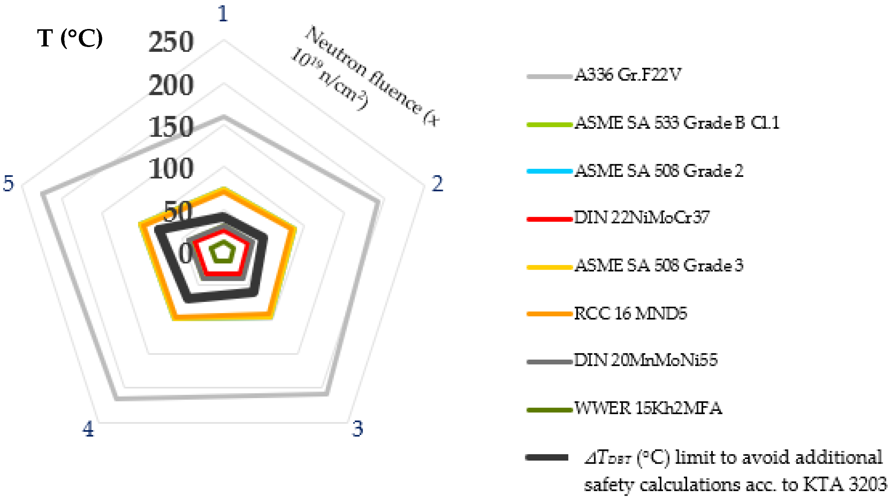
| KTA 3203 [59] | Some constraints are imposed to reduce susceptibility to irradiation embrittlement (using as a reference the R.G. 1.99 Rev.2 model): |
| GOST/PNAE |
| R.G. 1.99 Rev.2 | NUREG/CR-6551 | ASTM E 900-02 | RCC-M | KTA 3203 | PNAE |
|---|---|---|---|---|---|
| Cu ≤ 0.25, ∀ 0 < Ni ≤ 0.2 and ∀P (wt%) Cu ≤ 0.20, ∀ 0.2 < Ni ≤ 0.4 ∀P (wt%) Cu ≤ 0.16, ∀ 0.4 < Ni ≤ 0.6 ∀P (wt%) Cu ≤ 0.14, ∀ 0.6 < Ni ≤ 0.8 ∀P (wt%) Cu ≤ 0.13, ∀ 0.8 < Ni ≤ 1.2 ∀P (wt%) | 0.15 ∀ Ni wt% < 0.6 | 0.15 ∀ Ni wt% 0.2 only if Ni wt% < 0.4 | 0.05 ∀ Ni wt% and P < 0.02 wt.% | Cu ≤ 0.15%, ∀ 0 < Ni ≤ 1.1 Ni ≤ 1.1%, ∀ 0 < Cu ≤ 0.15 | 0.06 ∀ Ni wt% and P < 0.02 wt.% |
| ASME B&PV XI | KTA | RCC-M | Russian (GOST) |
|---|---|---|---|
| t > 300 mm → a/c = 1/3, a = 75 mm 100 mm > t ≤ 300 mm → a/c = 1/3, a = t/4 t ≤ 100 mm → a/c = 1/3, a = 25 mm | a = 1/4t 2c = 1.5t | a = min (0.25 t, 20 mm) t > 40 mm a/2c = 1/6 | a = t/4 a/c = 1/3 |
Publisher’s Note: MDPI stays neutral with regard to jurisdictional claims in published maps and institutional affiliations. |
© 2021 by the authors. Licensee MDPI, Basel, Switzerland. This article is an open access article distributed under the terms and conditions of the Creative Commons Attribution (CC BY) license (https://creativecommons.org/licenses/by/4.0/).
Share and Cite
Rodríguez-Prieto, A.; Camacho, A.M.; Mendoza, C.; Kickhofel, J.; Lomonaco, G. Evolution of Standardized Specifications on Materials, Manufacturing and In-Service Inspection of Nuclear Reactor Vessels. Sustainability 2021, 13, 10510. https://0-doi-org.brum.beds.ac.uk/10.3390/su131910510
Rodríguez-Prieto A, Camacho AM, Mendoza C, Kickhofel J, Lomonaco G. Evolution of Standardized Specifications on Materials, Manufacturing and In-Service Inspection of Nuclear Reactor Vessels. Sustainability. 2021; 13(19):10510. https://0-doi-org.brum.beds.ac.uk/10.3390/su131910510
Chicago/Turabian StyleRodríguez-Prieto, Alvaro, Ana María Camacho, Carlos Mendoza, John Kickhofel, and Guglielmo Lomonaco. 2021. "Evolution of Standardized Specifications on Materials, Manufacturing and In-Service Inspection of Nuclear Reactor Vessels" Sustainability 13, no. 19: 10510. https://0-doi-org.brum.beds.ac.uk/10.3390/su131910510