

Numerical Investigation of Flow Channel Design and Tapered Slope Effects on PEM Fuel Cell Performance

School of Automotive Studies, Tongji University, Shanghai 200092, China
*
Author to whom correspondence should be addressed.
Sustainability 2022, 14(18), 11167; https://0-doi-org.brum.beds.ac.uk/10.3390/su141811167
Submission received: 13 August 2022
/
Revised: 5 September 2022
/
Accepted: 5 September 2022
/
Published: 6 September 2022
(This article belongs to the Special Issue Intelligent Technologies in Energy Management of New Energy Vehicle)
Abstract
:High-power proton exchange membrane (PEM) fuel cell vehicles are important for the realization of carbon neutrality in transportation. However, it is difficult to maintain enough fuel supply and quick water removal capacity at a high current density where reactant gas transportation and water concentration are directly affected by flow channel configurations. This study aims to investigate the tapered slope effects of a flow channel on fuel cell performance using a 3-D CFD model. The positive, negative, zero and hybrid tapered slopes are proposed to illustrate the fuel cell voltage, reactant gas and water vapor concentration in the flow channels. Among them, the flow channel with a positive tapered slope performs better, especially at a high current density. Then, the positive tapered slope effects are discussed, including different tapered slopes, inlet depths and widths of flow channels. The results show that the larger the tapered slope, the smaller the depth and width, and the better the fuel cell performs; the corresponding current densities are increased by a maximum of 6.53%, 12.72% and 61.13%. The outcomes stated above provide a key direction for flow channel design that can particularly achieve higher fuel cell power density at high current densities.
1. Introduction
With the increasing concern for the environment and energy for a sustainable world, PEM fuel cells are not only important for vehicular power generation but can also be used as electrochemical generators to solve the current energy crisis [1,2]. Due to the current background of global decarbonization, renewable energies are being considered and developed. However, renewable energy sources such as solar energy and wind energy are unstable and intermittent during generation [3]. Hence, the employment of certain energy storage and generating systems can greatly improve the utilization rate and stability of renewable energy [4]. Electrolyzer and PEM fuel cells can be combined to tackle this issue, owing to their advantages of high energy efficiency, low operating temperature, quick start-up, zero pollution emissions [5,6,7], and also the abundant hydrogen and oxygen in nature. However, at present, the high power density of fuel cells is still a major issue, hindering the further large-scale commercialization development of fuel cell vehicles [8], which is mainly restricted due to the concentration polarization loss at the high current density required for the automotive application of fuel cells [9] and due to difficulties in maintaining enough fuel supply and quick water removal capacity in fuel cell flow channels [10,11].
In the automotive application of fuel cells, there is a increasingly clear requirement for a high current density to achieve high power density, especially in thin metal bipolar plates (BPPs) [12]. However, the field of high current density augmentation is quite broad, including material properties [13], operating parameters [14], energy management and strategy [15,16] and flow channel geometrical configurations [17,18], etc. Fuel cell flow channels must be particularly well designed since they play two transportation roles with reactant gas supply and exhaust water removal [19,20].
The insufficient transportation of a reactant gas supply may cause a deficient reactant gas concentration to be provided to the electrode surface, increasing the concentration polarization loss at the high current density [21,22]. Otherwise, if the reactant water vapor concentration produced by the electrode surface at a high current density is too much, it can easily lead to water accumulation and critical flooding problems in the flow channel and especially in the GDL hole [23], further hindering the continuous reactant fuel supply and enlarging the fuel cell concentration polarization loss [24,25]. In addition, the flow channels should also maintain enough pressure drop to push the reactant water from the electrode surface in a timely manner through the flow channel to the exit of the fuel cell stack [26]; meanwhile, this does not indicate excessive drying of the membrane in order to maintain the proper proton conductivity of membrane. This is because if all the reactant water is pushed out completely, the proton conductivity of the membrane will reduce sharply, and it will be difficult to realize high current density applications. When hydrated, the Nafion membrane undergoes microphase separation due to the hydrophobic and hydrophilic domains and thus provides transportation channels for the protons [27]. Thereby, a flow channel’s configuration is a potential way to improve the fuel cell output characteristics at high current density, which facilitates the reactant gas and water concentration flowing and diffusing to the catalyst layers (CLs) for the electrochemical reaction.
In the past two decades, numerical simulations via computational fluid dynamics (CFD) have often been implemented in fuel cell flow channel design to improve transportation to the electrode surface [28,29,30,31,32,33,34]. Many research works have concentrated on the fuel cell flow channel configuration to promote excellent reactant gas flow to the electrode surface and water removal capacity [35,36,37,38], and they have mainly been based on flow channel patterns and flow channel configuration [39,40,41].
Carcadea et al. [42] investigated the effects of the cross-section dimensions of flow channels on fuel cell performance. Three multi-serpentine flow channels were analyzed by varying the channel and rib width. Simulation results showed that a decreasing channel width (thin flow channel design) had a positive effect, especially at a high current density. Kreesaeng et al. [43] studied the effects of the channel to rib ratio of the cathode flow channel on the fuel cell performance based on a 3-D CFD model. The results showed that the optimal channel to rib ratio will lead to an increase in the oxygen molar concentration at the electrode surface and an increase in fuel cell performance. Similarly, Kerkoub et al. [44] studied the channel to rib width ratio of three flow channel types, including serpentine, interdigitated and parallel, on the PEM fuel cell performance via 3-D CFD models. The results indicated that the channel to rib width ratio has little effect on the fuel cell performance at a low current density, while having a significant effect at low operating voltages (i.e., high current density). Choi et al. [45] investigated the effects of channel depth and width on fuel cell performance. They found that the pressure drop increases with the channel depth. Moreover, the channel width is also important to the voltage compared to the channel depth.
In addition to conventional channel flow configurations, some researchers have investigated novel flow channels. Yan et al. [46] proposed two flow channels: one with a wavy channel bottom and the other with a deceasing channel depth. The results showed that the latter design can increase the gas flow velocity along the flow channel direction, thus improving the water removal or avoiding water accumulation that may lead to flooding; the experiment results validated that this tapered flow channel significantly improved the fuel cell performance at a high current density.
Mancusi et al. [9] established a 3-D two-phase model and analyzed the tapered flow channel. The effect of tapered slopes was shown to be more significant at high current densities, which means increasing the tapered slope is helpful for high water removal capacity due to an obvious increase in pressure drop. In the study of Chowdhury et al. [47], four different flow fields were designed by varying the channel depth from inlet to outlet. The results showed that the decreasing channel depth caused a better diffusion of species. In addition, the water removal and current density were found to be better compared to the conventional flow fields. Wang et al. [48] also built two fuel cell tapered flow fields by varying channel height and width, and an experiment and simulation were both performed. The results proved that tapered flow fields with higher flow velocities can significantly enhance water removal capacity, which can avoid the mass transport limitation and improve the fuel cell performance at a higher current density. Kumar et al. [49] compared the performance of the serpentine flow field and the tapered channels. The results showed that the tapered flow channels showed an improvement of 15% in the current density due to better reactant gas transport to catalyst layers. Further, the Nyquist results also revealed a better diffusion of reactant gases to CLs and the better removal of water in the flow channels. Han et al. [50] investigated the effects of a more detailed structure design in tapered flow channels, and the liquid water was numerically studied. The results indicated that a tapered flow channel configuration could improve the removal efficiency that existed in the flow channels and the maximum removal time could be reduced by 24.4% compared to the standard conventional flow channels. Similarly, the mass transfer and average current density were also improved due to the enhanced concentration of reactant gas near the CLs.
The researchers above investigated the effects of typical flow channel types (straight, serpent, interdigitated, etc.) and dimensions (length, height, width, novel cross-section, etc.) on reactant species transportation and the PEM fuel cell performance in a relatively systematic and comprehensive way, which is based on a similar method that is the combination of CFD and the fuel cell electrochemistry theory. However, most studies focused on the conventional flow channel configuration, which is non-gradient; meanwhile, it became possible to adopt the tapered slope effect of flow channel configuration on the design of thin metal BPPs. Moreover, few studies have combined electrochemical simulation and dynamic fluids simulation to provide a more detailed and comprehensive analysis of the more advantageous tapered flow channels.
Therefore, the purpose of this study is to investigate the tapered slope effects of flow channels using a 3-D CFD model to evaluate the fuel cell performance. The positive, negative, zero and hybrid tapered slopes are proposed to illustrate the fuel cell performance, and species transport and water removal at a high current density are also particularly studied, i.e., the concentration polarization. Then, for the PEM fuel cell CFD model with the positive tapered slope flow channel, the effects of the tapered slope and the inlet depth and width of the flow channel on fuel cell performance are systematically investigated. This work can provide a novel direction for flow channel design that can particularly improve the fuel cell high power density at a high current density.
2. Model Description
2.1. Mathematical Model
A PEM fuel cell is a multi-physics and multi-disciplinary complex energy conversation system, which contains complicated coupled phenomena. The numerical modeling of these phenomena involves differential conservation equations which are expressed in Table 1, and the involved parameters are shown in detail in Table 2.
2.2. Simulation Model
The 3-D single flow channel PEM fuel cell model is shown in Figure 1, which includes gas diffusion layers (GDLs), CLs, a PEM and BPPs with flow channels. The dimensional parameters are shown in Table 3.
Table 4 shows the main material properties involved in the numerical model. In addition, the necessary hypotheses are also considered, e.g., the gases are ideally incompressible, the flow state is laminar and the effect of gravity is not considered.
As for boundary conditions, at the anode inlet, the hydrogen mass fraction is set to 0.8 and the water vapor mass fraction is 0.2. At the cathode inlet, the oxygen mass fraction is set to 0.196 and the water vapor mass fraction is 0.18. The fuel cell operating temperature is set to 353 K, and the gas pressure at the outlet is 0 Pa, with back pressure for simplification.
3. Results and Discussion
3.1. Effects of Flow Channel Type
Four PEM fuel cell models with tapered flow channels with positive, negative, zero and hybrid types are proposed, and cross-sections of the flow channels at the centerline, as shown in the dashed box in Figure 1 (z-direction, z = 0 at the hydrogen inlet and z = 0.05 at the air inlet) are illustrated in Figure 2, including positive, negative, zero and hybrid.
Figure 3 shows the polarization curves of four different PEM fuel cells and the pressure drop inside the flow channel along the gas flow direction (z-direction). It can be found that the fuel cell voltages of four different tapered types of flow channels are nearly the same at a low current density, while at a high current density, the positive tapered flow channel performs significantly better than the others, since the fuel cell electrochemical reaction can produce more water at a higher current density, which will hinder the reactant gas diffusion and decrease the electrochemical reaction. Figure 3b shows that the gas pressure drop from the inlet to the outlet of the tapered flow channel is higher than the others, which means it is more beneficial to remove water, and that is why the corresponding model outperforms, especially at a high current density. To validate this statement, the voltage cases of 0.55 V are chosen for further analysis, as shown in Figure 4.
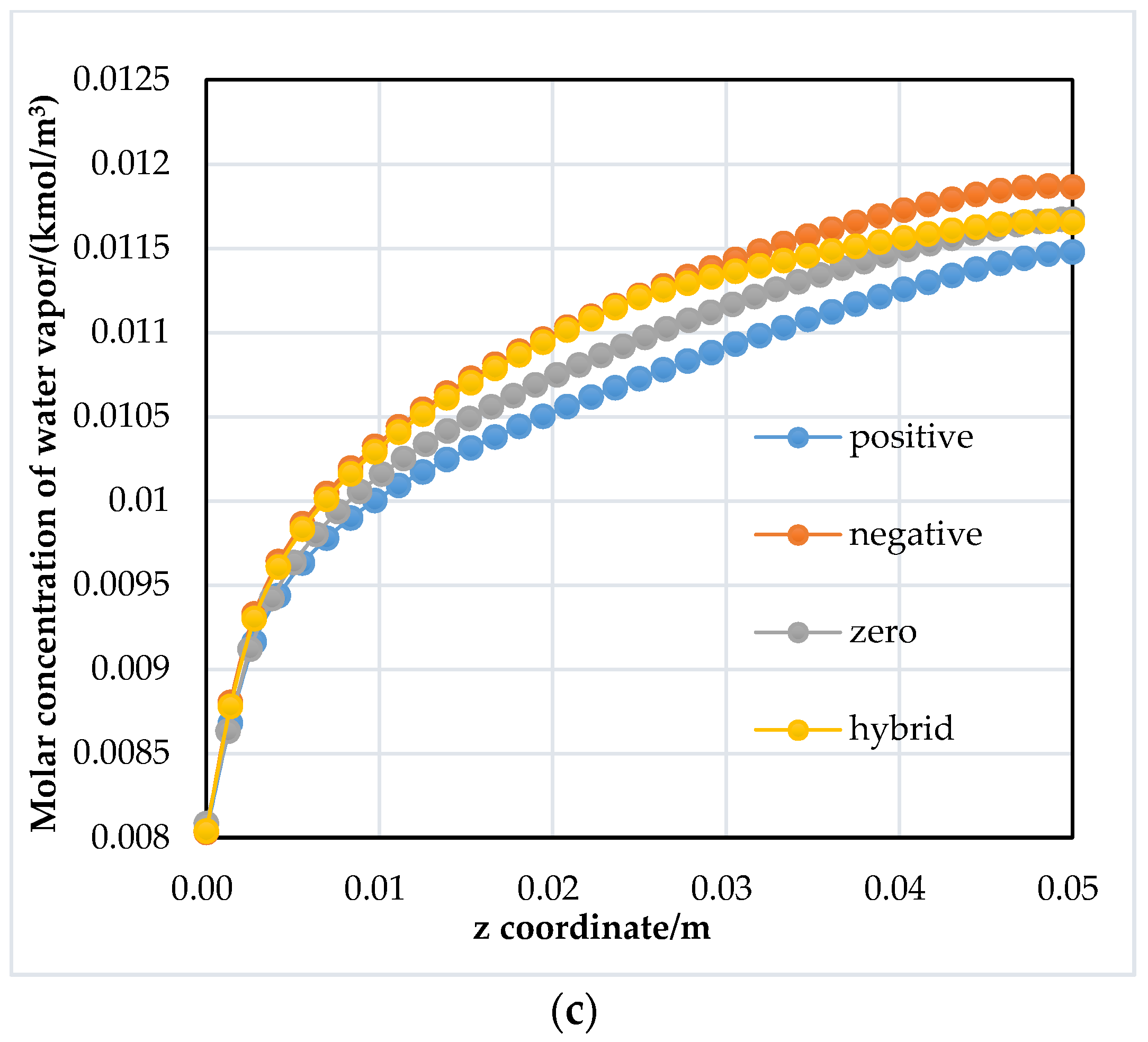
Figure 4 shows the molar concentration distribution of hydrogen, oxygen and water vapor at the electrode surface between the GDL and CL for four different tapered flow channels. It can be found that the model with a positive tapered flow channel has higher hydrogen and oxygen concentration, indicating that it is feasible to provide more reactant fuel to the electrode surface and promote the fuel cell electrochemical reaction. Moreover, as also can be found in Figure 4c, the water concentration of the model with a positive tapered flow channel is the lowest, which corroborates that the positive tapered flow channel is indeed more beneficial to the removal of reactant water.
From the above analysis of four different tapered flow channels, we can find that the positive tapered flow channel has both the advantages of enough gas supply and excellent water removal capacity; in the next section, the positive tapered flow channel is illustrated to obtain the optimal configurational dimension for the best PEM fuel cell performance at the high current density.
3.2. Tapered Slope Effects of Flow Channel on PEM Fuel Cell Performance
3.2.1. Different Tapered Slopes with the Same Inlet Depth
Four different flow channels with different tapered slopes are proposed, as shown in Figure 5. To make the results more distinguishable, the channel inlet depths of the four models are all set to the same value, 1 mm, and the positive tapered slopes are 0.9, 0.7, 0.5 and 0.3.
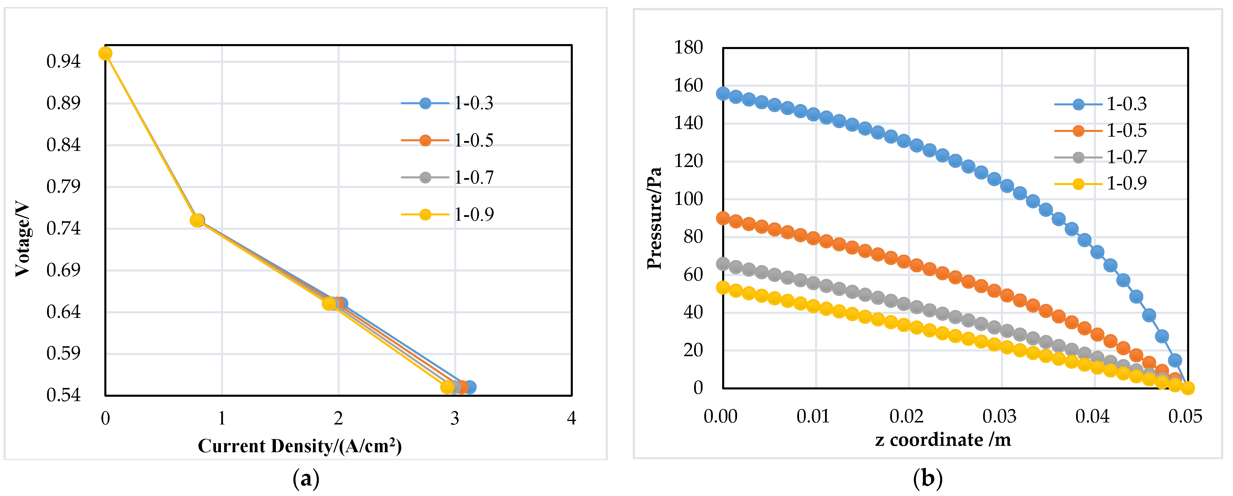
Figure 6a shows the polarization curves of four tapered slope flow channels, and Figure 6b shows the pressure distribution inside the flow channel. The larger the tapered slope, the better the fuel cell performs, especially at a high current density, which can also be attributed to the increasing concentration of reactant gas for the electrochemical reaction and more water removal. Comparing the current densities at 0.55 V (3.1245 and 2.9328 A/cm2, respectively), it can be found that the current density of the cell with the largest flow channel tapered degree is increased by nearly 6.53%. Cases of 0.55 V are also chosen for further analysis in Figure 7.
The molar concentration distribution of hydrogen, oxygen and water vapor at the electrode interface of GDL and CL along the z-direction of four models is illustrated in Figure 7. Similarly, it can be found that the hydrogen and oxygen concentrations both become higher owing to the high tapered slope, which leads to reactant gas having a larger velocity component directed towards the electrode surface. Furthermore, the water vapor concentration becomes lower, which is better for the continuous fuel supply. These phenomena can explain the fuel cell performance enhancement with the tapered slope. However, a limitation exists in the tapered slope, because an excessively large tapered slope may lead to a much higher gas pressure drop when the flow channel length increases, which should be balanced with an air compressor control strategy for the high net output power of the fuel cell engine [51].
3.2.2. Different Inlet Depths with the Same Tapered Slope
To investigate the effects of flow channel depth, four different depths of flow channels with the same tapered slope, such as 0.4-0.1, 0.6-0.3, 0.8-0.5 and 1-0.7, are built, and the schematic cross-sections are shown in Figure 8.
Figure 9 shows the polarization curves and the pressure distribution inside the anode flow channel of four different depth models with the same tapered slope, from which it can be found that the smaller the tapered channel depth, the better the fuel cell performs, especially at high current density. It can be found that current density at 0.55 V of the cell with the smallest flow channel depth is increased by nearly 12.72% (the highest and lowest current densities are 3.3717 and 2.9913 A/cm2). This can be also seen from Figure 9b, and it is obvious that the smallest channel depth makes the pressure in the flow channel significantly higher, which helps reactants diffuse to the CL easily and remove more reactant water. Further analysis is shown in Figure 10, and the voltage in all cases is 0.55 V.
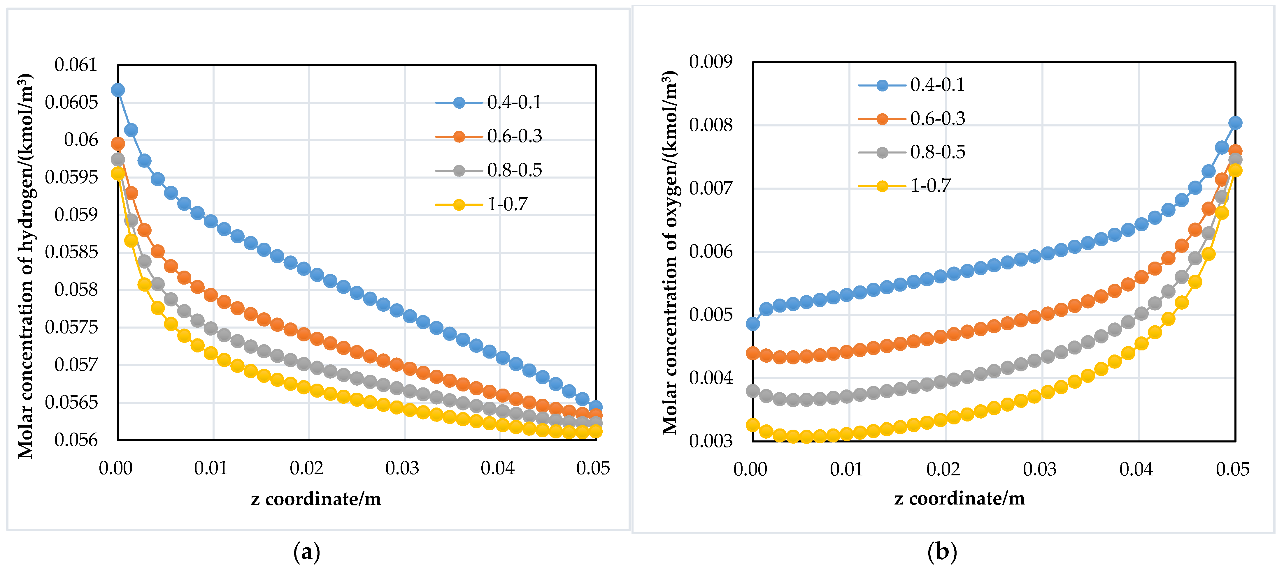
Similarly, the molar concentration distribution of hydrogen, oxygen and water vapor in four models is illustrated in Figure 10, which shows the same behavior that the reactants’ concentrations increase along with the decrease in flow channel depth. However, a limitation also exists: a too-small channel depth will produce an extremely large gas pressure drop, which will consume more power of the fuel cell air compressor.
3.2.3. Different Flow Channel Widths with the Same Tapered Slope and Inlet Depth
Under the same tapered slope and inlet depth of the fuel cell flow channel, the effects of channel width on species diffusion to the electrode surface and gas pressure drop are studied. Four fuel cell flow channel models with different channel widths are illustrated, such as 0.4 mm, 0.6 mm, 0.8 mm and 1 mm, and the channel to width ratio keeps constant, i.e., 1.
Figure 11 shows the polarization curves and the pressure distribution inside the anode flow channel of four models. It is obvious that the fuel cell model with a smaller channel width performs better at both low and high current densities, and the difference is more pronounced at a high current density. At 0.55 V, the current density of the cell with the smallest flow channel width increases by nearly 61.13% compared to that of the fuel cell with the largest channel width (3.8252 and 2.3740 A/cm2, respectively). Figure 11b shows that a larger gas pressure drop can help reactant fuel easily diffuse to the CL and remove more reactant water. Cases of 0.55 V are also selected for further analysis in Figure 12.
Figure 12 shows the molar concentration distribution of hydrogen, oxygen and water at the electrode interface of GDL and CL in four models. It can be found in Figure 12a,c that the molar concentration of hydrogen and water complies with the trend in Figure 11. As shown in Figure 12b, the concentration of oxygen becomes lower with the decrease in channel width since the narrow cathode flow channel has a limited oxygen concentration, while the electrochemical reaction requires large amounts of oxygen. Thus, if possible, the cathode flow channel should maintain a large enough width. It can be found that under the limited cathode flow channel width, the fuel cell performance is mainly influenced by the concentration of hydrogen in the CL, and the small channel width is favorable to enhancing hydrogen diffusion and water removal, which are thus beneficial for improving the fuel cell performance.
4. Conclusions
Many countries and regions have put forward clear development plans for high-power PEM fuel cell vehicles in transportation. Tapered slope flow channels can be potentially designed and optimized to provide enough fuel supply and quick water removal capacity at a high current density. This study compares the effects of different tapered flow channels on the PEM fuel cell performance and further investigates the effects of different tapered slopes of fuel cell flow channels, inlet depths and channel widths on the PEM fuel cell performance. The main conclusions are as follows:
- For the positive, negative, zero and hybrid tapered fuel cell flow channels, the positive tapered fuel cell flow channel is favorable for the high current density of a large fuel cell stack for automotive application, owing to high reactant gas diffusion with a large gas pressure drop and water removal capacity in the positive tapered flow channels.
- A certain positive tapered slope and a small depth of flow channel can amplify the advantageous effects of tapered flow channels. Their corresponding current densities are increased by a maximum of 6.53% and 12.72%.
- Channel width will significantly affect the diffusion of reactants; a small channel width will largely improve the diffusion of hydrogen and maintain a large gas pressure drop, thus facilitating reactant gas diffusion and water removal. Its corresponding current density is increased by a maximum of 61.13%.
This study provides a flow channel design direction that can particularly improve fuel cell performance at a high current density. However, this type of flow channel with a tapered slope will also need a large gas pressure drop and require large input pressure at the fuel cell inlet, which means there will be a higher power consumption requirement on the fuel cell air compressor.
Author Contributions
Conceptualization, Z.Z. and S.W.; methodology, Z.Z.; software, S.W. and H.M.; validation, Z.Z. and S.W.; resources, Z.Z.; writing—original draft preparation, Z.Z. and S.W.; writing—review and editing, Z.Z.; funding acquisition, Z.Z. and T.Z. All authors have read and agreed to the published version of the manuscript.
Funding
This research was funded by the Natural Science Foundation of Shanghai, grant number 22ZR1466800.
Institutional Review Board Statement
Not applicable.
Informed Consent Statement
Not applicable.
Data Availability Statement
Not applicable.
Conflicts of Interest
The authors declare no conflict of interest.
References
- Jiao, K.; Xuan, J.; Du, Q.; Guiver, M.D. Designing the next generation of proton-exchange membrane fuel cells. Nature 2021, 595, 361–369. [Google Scholar] [CrossRef]
- Xu, J.; Zhang, C.; Wan, Z.; Chen, X.; Chan, S.H.; Tu, Z. Progress and perspectives of integrated thermal management systems in PEM fuel cell vehicles: A review. Renew. Sustain. Energy Rev. 2022, 155, 111908. [Google Scholar] [CrossRef]
- Chen, Z.; Yu, W.; Liu, Y.; Zeng, Y.; He, Q.; Tan, P.; Ni, M. Mathematical modeling and numerical analysis of alkaline zinc-iron flow batteries for energy storage applications. Chem. Eng. J. 2021, 405, 126684–126696. [Google Scholar] [CrossRef]
- Xie, Y.; Cui, Y.; Wu, D.; Zeng, Y.; Sun, L. Economic analysis of hydrogen-powered data center. Int. J. Hydrogen Energy 2021, 46, 27841–27850. [Google Scholar] [CrossRef]
- Weber, A.Z.; Borup, R.L.; Darling, R.M.; Das, P.K.; Dursch, T.J. A critical review of modeling transport phenomena in polymer-electrolyte fuel cells. J. Electrochem. Soc. 2014, 161, 1254–1299. [Google Scholar] [CrossRef]
- Das, V.; Padmanaban, S.; Venkitusamy, K.; Selvamuthukumaran, R.; Blaabjerg, F. Recent advances and challenges of fuel cell based power system architectures and control-A review. Renew. Sustain. Energy Rev. 2017, 73, 10–18. [Google Scholar] [CrossRef]
- Hu, D.; Wang, Y.; Li, J.; Yang, Q.; Wang, J. Investigation of optimal operating temperature for the PEMFC and its tracking control for energy saving in vehicle applications. Energy Convers. Manag. 2021, 249, 114842. [Google Scholar] [CrossRef]
- Jiao, K.; Ni, M. Challenges and opportunities in modelling of proton exchange membrane fuel cells (PEMFC). Int. J. Energy Res. 2017, 41, 1793–1797. [Google Scholar] [CrossRef]
- Mancusi, E.; Fontana, E.; Ulson de Souza, A.A.; Guelli Ulson de Souza, S.M.A. Numerical study of two-phase flow patterns in the gas channel of PEM fuel cells with tapered flow field design. Int. J. Hydrogen Energy 2014, 39, 2261–2273. [Google Scholar] [CrossRef]
- Azarafza, A.; Ismail, M.S.; Rezakazemi, M.; Pourkashanian, M. Comparative study of conventional and unconventional designs of cathode flow fields in PEM fuel cell. Renew. Sustain. Energy Rev. 2019, 116, 350–366. [Google Scholar] [CrossRef]
- Pei, H.; Meng, K.; Chang, H.; Zhang, Y.; Shen, J.; Tu, Z.; Chan, S.H. Performance improvement in a proton exchange membrane fuel cell with separated coolant flow channels in the anode and cathode. Energy Convers. Manag. 2019, 187, 76–82. [Google Scholar] [CrossRef]
- Qiu, D.; Peng, L.; Yi, P.; Lai, X.; Lehnert, W. Flow channel design for metallic bipolar plates in proton exchange membrane fuel cells: Experiments. Energy Convers. Manag. 2018, 174, 814–823. [Google Scholar] [CrossRef]
- Shen, S.; Chen, J.; Yan, X.; Cheng, X.; Zhao, L.; Ren, Z.; Li, L.; Zhang, J. Insights into properties of non-precious metal catalyst (NPMC)-based catalyst layer for proton exchange membrane fuel cells. J. Power Sources 2021, 496, 229817. [Google Scholar] [CrossRef]
- Ji, X.; Wang, X.; Li, Y.; Guo, J.; Yang, Z.; Hao, D. Sensitivity analysis of operating parameters on a 65 kW proton exchange membrane fuel cell stack performances. Energy Rep. 2022, 8, 521–527. [Google Scholar] [CrossRef]
- Yi, F.; Lu, D.; Wang, X.; Pan, C.; Tao, Y.; Zhou, J.; Zhao, C. Energy Management Strategy for Hybrid Energy Storage Electric Vehicles Based on Pontryagin’s Minimum Principle Considering Battery Degradation. Sustainability 2022, 14, 1214. [Google Scholar] [CrossRef]
- Zhou, J.; Feng, C.; Su, Q.; Jiang, S.; Fan, Z.; Ruan, J.; Sun, S.; Hu, L. The Multi-Objective Optimization of Powertrain Design and Energy Management Strategy for Fuel Cell–Battery Electric Vehicle. Sustainability 2022, 14, 6320. [Google Scholar] [CrossRef]
- Mohammedi, A.; Sahli, Y.; Moussa, H.B. 3D investigation of the channel cross-section configuration effect on the power delivered by PEMFCs with straight channels. Fuel 2020, 263, 116713. [Google Scholar] [CrossRef]
- Pan, W.; Wang, P.; Chen, X.; Wang, F.; Dai, G. Combined effects of flow channel configuration and operating conditions on PEM fuel cell performance. Energy Convers. Manag. 2020, 220, 113046. [Google Scholar] [CrossRef]
- Wu, H.-W. A review of recent development: Transport and performance modeling of PEM fuel cells. Appl. Energy 2016, 165, 81–106. [Google Scholar] [CrossRef]
- Shen, J.; Tu, Z.; Chan, S.H. Evaluation criterion of different flow field patterns in a proton exchange membrane fuel cell. Energy Convers. Manag. 2020, 213, 112841. [Google Scholar] [CrossRef]
- Li, S.; Yuan, J.; Xie, G.; Sunden, B. Numerical investigation of transport phenomena in high temperature proton exchange membrane fuel cells with different flow field designs. Numer. Heat Transf. Part A Appl. 2017, 72, 807–820. [Google Scholar] [CrossRef]
- Lim, K.; Vaz, N.; Lee, J.; Ju, H. Advantages and disadvantages of various cathode flow field designs for a polymer electrolyte membrane fuel cell. Int. J. Heat Mass Transf. 2020, 163, 120497. [Google Scholar] [CrossRef]
- Chen, R.; Qin, Y.; Ma, S.; Du, Q. Numerical simulation of liquid water emerging and transport in the flow channel of PEMFC using the volume of fluid method. Int. J. Hydrogen Energy 2020, 45, 29861–29873. [Google Scholar] [CrossRef]
- Pei, P.; Li, Y.; Xu, H.; Wu, Z. A review on water fault diagnosis of PEMFC associated with the pressure drop. Appl. Energy 2016, 173, 366–385. [Google Scholar] [CrossRef]
- Chen, X.; Yu, Z.; Yang, C.; Chen, Y.; Jin, C.; Ding, Y.; Li, W.; Wan, Z. Performance investigation on a novel 3D wave flow channel design for PEMFC. Int. J. Hydrog. Energy 2021, 46, 11127–11139. [Google Scholar] [CrossRef]
- Zeng, T.; Zhang, C.; Zhou, A.; Wu, Q.; Deng, C.; Chan, S.H.; Chen, J.; Foley, A.M. Enhancing reactant mass transfer inside fuel cells to improve dynamic performance via intelligent hydrogen pressure contro. Energy 2021, 230, 120620. [Google Scholar] [CrossRef]
- Sun, C.Y.; Zhang, H.; Luo, X.D.; Chen, N. A comparative study of Nafion and sulfonated poly(ether ether ketone) membrane performance for iron-chromium redox flow battery. Ionics 2019, 25, 4219–4229. [Google Scholar] [CrossRef]
- Kahveci, E.E.; Taymaz, I. Assessment of single-serpentine PEM fuel cell model developed by computational fluid dynamics. Fuel 2018, 217, 51–58. [Google Scholar] [CrossRef]
- Thomas, S.; Bates, A.; Park, S. An experimental and simulation study of novel channel designs for open-cathode high-temperature polymer electrolyte membrane fuel cells. Appl. Energy 2016, 165, 765–776. [Google Scholar] [CrossRef]
- Chowdhury, M.Z.; Genc, O.; Toros, S. Numerical optimization of channel to land width ratio for PEM fuel cell. Int. J. Hydrog. Energy 2018, 43, 10798–10809. [Google Scholar] [CrossRef]
- Ionescu, V.; Buzbuchi, N. PEMFC Two-dimensional FEM model to study the effects of gas flow channels geometry on reactant species transport. Energy Procedia 2017, 112, 390–397. [Google Scholar] [CrossRef]
- Wu, J.; Li, Y.; Wang, Y. Three-dimension simulation of two-phase flows in a thin gas flow channel of PEM fuel cell using a volume of fluid method. Int. J. Hydrog. Energy 2020, 45, 29730–29737. [Google Scholar] [CrossRef]
- Chen, C.; Wang, C.; Zhang, Z. A novel channel design and heat and mass transfer analysis of fuel cells. Energy Convers. Manag. 2022, 254, 115273. [Google Scholar] [CrossRef]
- Heidary, H.; Kermani, M.J.; Advani, S.G.; Prasad, A.K. Experimental investigation of in-line and staggered blockages in parallel flowfield channels of PEM fuel cells. Int. J. Hydrog. Energy 2016, 41, 6885–6893. [Google Scholar] [CrossRef]
- Abdulla, S.; Patnaikuni, V.S. Detailed analysis of polymer electrolyte membrane fuel cell with enhanced cross-flow split serpentine flow field design. Int. J. Energy Res. 2019, 43, 2806–2820. [Google Scholar] [CrossRef]
- Min, C.; Li, F.; Gao, X.; Wang, K.; Rao, Z. Secondary flow on the performance of PEMFC with blocks in the serpentine flow field. Int. J. Hydrog. Energy 2022, 47, 28945–28955. [Google Scholar] [CrossRef]
- Chen, H.; Guo, H.; Ye, F.; Ma, C.F. A numerical study of orientated-type flow channels with porous-blocked baffles of proton exchange membrane fuel cells. Int. J. Hydrog. Energy 2021, 46, 29443–29458. [Google Scholar] [CrossRef]
- Ebrahimzadeh, A.A.; Khazaee, I.; Fasihfar, A. Experimental and numerical investigation of obstacle effect on the performance of PEM fuel cell. Int. J. Heat Mass Transf. 2019, 141, 891–904. [Google Scholar] [CrossRef]
- Mei, N.; Xu, X.; Hu, H.; Li, C. Trapezoidal channel proton-exchange membrane fuel cell performance study. Energy Fuels 2020, 34, 16729–16735. [Google Scholar] [CrossRef]
- Ghanbarian, A.; Kermani, M.J.; Scholta, J.; Abdollahzadeh, M. Polymer electrolyte membrane fuel cell flow field design criteria—Application to parallel serpentine flow patterns. Energy Convers. Manag. 2018, 166, 281–296. [Google Scholar] [CrossRef] [Green Version]
- Alizadeh, E.; Rahimi-Esbo, M.; Rahgoshay, S.M.; Saadat, S.H.M.; Khorshidian, M. Numerical and experimental investigation of cascade type serpentine flow field of reactant gases for improving performance of PEM fuel cell. Int. J. Hydrog. Energy 2017, 42, 14708–14724. [Google Scholar] [CrossRef]
- Carcadea, E.; Ismail, M.S.; Ingham, D.B.; Patularu, L.; Schitea, D.; Marinoiu, A.; Ion-Ebrasu, D.; Mocanu, D.; Varlam, M. Effects of geometrical dimensions of flow channels of a large-active-area PEM fuel cell: A CFD study. Int. J. Hydrog. Energy 2021, 46, 13572–13582. [Google Scholar] [CrossRef]
- Kreesaeng, S.; Chalermsinsuwan, B.; Piumsomboon, P. Effect of Channel Designs on Open-Cathode PEM Fuel Cell Performance: A Computational Study. Energy Procedia 2015, 79, 733–745. [Google Scholar] [CrossRef]
- Kerkoub, Y.; Benzaoui, A.; Haddad, F.; Ziari, Y.K. Channel to rib width ratio influence with various flow field designs on performance of PEM fuel cell. Energy Convers. Manag. 2018, 174, 260–275. [Google Scholar] [CrossRef]
- Choi, K.-S.; Kim, H.-M.; Moon, S.-M. Numerical studies on the geometrical characterization of serpentine flow-field for efficient PEMFC. Int. J. Hydrog. Energy 2011, 36, 1613–1627. [Google Scholar] [CrossRef]
- Yan, X.; Guan, C.; Zhang, Y.; Jiang, K.; Wei, G.; Cheng, X.; Shen, S.; Zhang, J. Flow field design with 3D geometry for proton exchange membrane fuel cells. Appl. Therm. Eng. 2019, 147, 1107–1114. [Google Scholar] [CrossRef]
- Chowdhury, M.Z.; Akansu, Y.E. Novel convergent-divergent serpentine flow fields effect on PEM fuel cell performance. Int. J. Hydrog. Energy 2017, 42, 25686–25694. [Google Scholar] [CrossRef]
- Wang, C.; Zhang, Q.; Lu, J.; Shen, S.; Yan, X.; Zhu, F.; Cheng, X.; Zhang, J. Effect of height/width-tapered flow fields on the cell performance of polymer electrolyte membrane fuel cells. Int. J. Hydrog. Energy 2017, 42, 23107–23117. [Google Scholar] [CrossRef]
- Kumar, R.R.; Suresh, S.; Suthakar, T.; Singh, V.K. Experimental investigation on PEM fuel cell using serpentine with tapered flow channels. Int. J. Hydrog. Energy 2020, 45, 15642–15649. [Google Scholar] [CrossRef]
- Lei, H.; Huang, H.; Li, C.; Pan, M.; Guo, X.; Chen, Y.; Liu, M.; Wang, T. Numerical simulation of water droplet transport characteristics in cathode channel of proton exchange membrane fuel cell with tapered slope structures. Int. J. Hydrog. Energy 2020, 45, 29331–29344. [Google Scholar] [CrossRef]
- Zhou, J.; Liu, J.; Su, Q.; Feng, C.; Wang, X.; Hu, D.; Yi, F.; Jia, C.; Fan, Z.; Jiang, S. Heat dissipation enhancement structure design of two-stage electric air compressor for fuel cell vehicles considering efficiency improvement. Sustainability 2022, 14, 7259. [Google Scholar] [CrossRef]
Figure 1.
Single flow channel model of PEM fuel cell.

Figure 2.
Schematic cross-sections of the different tapered flow channels.

Figure 3.
Fuel cell polarization characteristics and pressure distribution of four fuel cells with different flow channels: (a) polarization curves; (b) pressure at the anode flow channel along the z-direction.
Figure 3.
Fuel cell polarization characteristics and pressure distribution of four fuel cells with different flow channels: (a) polarization curves; (b) pressure at the anode flow channel along the z-direction.

Figure 4.
Species concentration at the electrode interface between the cathode GDL and CL of four fuel cells with different flow channels: (a) molar concentration of hydrogen; (b) molar concentration of oxygen; (c) water vapor concentration.
Figure 4.
Species concentration at the electrode interface between the cathode GDL and CL of four fuel cells with different flow channels: (a) molar concentration of hydrogen; (b) molar concentration of oxygen; (c) water vapor concentration.


Figure 5.
Schematic cross-sections of the flow channels with four tapered slopes.

Figure 6.
Fuel cell polarization characteristics and pressure distribution of four fuel cells with different flow channel tapered slopes: (a) polarization curves; (b) pressure at the anode flow channel along the z-direction.
Figure 6.
Fuel cell polarization characteristics and pressure distribution of four fuel cells with different flow channel tapered slopes: (a) polarization curves; (b) pressure at the anode flow channel along the z-direction.

Figure 7.
Species concentration at the electrode interface between the cathode GDL and CL of four fuel cells with different flow channel tapered slopes: (a) molar concentration of hydrogen; (b) molar concentration of oxygen; (c) water vapor concentration.
Figure 7.
Species concentration at the electrode interface between the cathode GDL and CL of four fuel cells with different flow channel tapered slopes: (a) molar concentration of hydrogen; (b) molar concentration of oxygen; (c) water vapor concentration.


Figure 8.
Schematic cross-sections of four flow channels with different depths.

Figure 9.
Fuel cell polarization characteristics and pressure distribution of four fuel cells with different flow channel depths: (a) polarization curves; (b) pressure at the anode flow channel along the z-direction.
Figure 9.
Fuel cell polarization characteristics and pressure distribution of four fuel cells with different flow channel depths: (a) polarization curves; (b) pressure at the anode flow channel along the z-direction.

Figure 10.
Species concentration at the electrode interface between the cathode GDL and CL of four fuel cells with different flow channel depths: (a) molar concentration of hydrogen; (b) molar concentration of oxygen; (c) water vapor concentration.
Figure 10.
Species concentration at the electrode interface between the cathode GDL and CL of four fuel cells with different flow channel depths: (a) molar concentration of hydrogen; (b) molar concentration of oxygen; (c) water vapor concentration.


Figure 11.
Fuel cell polarization characteristics and pressure distribution of four fuel cells with different flow channel widths: (a) polarization curves; (b) pressure at the anode flow channel along the z-direction.
Figure 11.
Fuel cell polarization characteristics and pressure distribution of four fuel cells with different flow channel widths: (a) polarization curves; (b) pressure at the anode flow channel along the z-direction.

Figure 12.
Species concentration at the electrode interface between the cathode GDL and CL of four fuel cells with different flow channel widths: (a) molar concentration of hydrogen; (b) molar concentration of oxygen; (c) water vapor concentration.
Figure 12.
Species concentration at the electrode interface between the cathode GDL and CL of four fuel cells with different flow channel widths: (a) molar concentration of hydrogen; (b) molar concentration of oxygen; (c) water vapor concentration.


Table 1.
Conservation equations of PEM fuel cells.
| Equation | Description * |
|---|---|
| mass conservation equation [44] | |
| momentum conservation equation [44] | |
| energy conservation equation [44] | |
| the Butler–Volmer equation [42] | . |
| current conservation equation [42] | |
| diffusion equation in the porous zone [10] |
* The subscript ,
represents the anode and cathode; k represents one of ,
,
and
;
,
represents the solid phase and membrane phase.
Table 2.
Description of the parameters in conservation equations.
| Parameters | Units | Description |
|---|---|---|
| porosity | ||
| kg·m−3 | gas density | |
| m·s−1 | gas velocity | |
| kmol·m−3 | mass source term | |
| kg·kmol−1 | molar mass | |
| C·mol−1 | Faraday constant | |
| A·m−3 | volumetric current density | |
| Pa | pressure | |
| kg·m−2·s−1 | momentum source term | |
| Pa·s | viscosity | |
| J·kg−1·K−1 | specific heat at constant pressure | |
| K | temperature | |
| W·m−1·K−1 | effective thermal conductivity | |
| W·m−3 | energy source term | |
| V | overpotential | |
| A·m−2 | reference exchange current density | |
| kmol·m−3 | molar concentration | |
| kmol·m−3 | reference molar concentration | |
| concentration index | ||
| charge transfer coefficient | ||
| s·m−1 | charge or electron conductivity | |
| V | phase potential | |
| A·m−3 | current source term | |
| liquid water saturation | ||
| liquid water saturation index | ||
| m2·s−1 | diffusion coefficient | |
| m2·s−1 | ||
| pressure index | ||
| K | reference temperature | |
| Pa | reference pressure | |
| к | m−2 | viscous resistance in the porous zone |
| kg·kmol−1 | molar mass of proton exchange membrane | |
| m−1 | specific surface area of the catalyst layer |
Table 3.
Dimensions of the single flow channel model.
| Component | Height/mm | Width/mm | Length/mm |
|---|---|---|---|
| BPP | 1.5 | 1.8 | 50 |
| GDL | 0.2 | 1.8 | 50 |
| CL | 0.01 | 1.8 | 50 |
| PEM | 0.03 | 1.8 | 50 |
Publisher’s Note: MDPI stays neutral with regard to jurisdictional claims in published maps and institutional affiliations. |
© 2022 by the authors. Licensee MDPI, Basel, Switzerland. This article is an open access article distributed under the terms and conditions of the Creative Commons Attribution (CC BY) license (https://creativecommons.org/licenses/by/4.0/).
Share and Cite
MDPI and ACS Style
Zhang, Z.; Wu, S.; Miao, H.; Zhang, T. Numerical Investigation of Flow Channel Design and Tapered Slope Effects on PEM Fuel Cell Performance. Sustainability 2022, 14, 11167. https://0-doi-org.brum.beds.ac.uk/10.3390/su141811167
AMA Style
Zhang Z, Wu S, Miao H, Zhang T. Numerical Investigation of Flow Channel Design and Tapered Slope Effects on PEM Fuel Cell Performance. Sustainability. 2022; 14(18):11167. https://0-doi-org.brum.beds.ac.uk/10.3390/su141811167
Chicago/Turabian StyleZhang, Zhiming, Sai Wu, Huimin Miao, and Tong Zhang. 2022. "Numerical Investigation of Flow Channel Design and Tapered Slope Effects on PEM Fuel Cell Performance" Sustainability 14, no. 18: 11167. https://0-doi-org.brum.beds.ac.uk/10.3390/su141811167
Note that from the first issue of 2016, this journal uses article numbers instead of page numbers. See further details here.