Article

Arrangement of Belleville Springs on Endplates Combined with Optimal Cross-Sectional Shape in PEMFC Stack Using Equivalent Beam Modeling and FEA

1
School of Automotive Studies, Tongji University, Shanghai 201804, China
2
School of Information and Electrical Engineering, Zhejiang University City College, Hangzhou 310015, China
3
School of Intelligent Manufacturing, Weifang University of Science and Technology, Weifang 262700, China
4
Zhengzhou Yutong Bus Co., Ltd., Zhengzhou 450016, China
5
College of Automotive Engineering, Chongqing University, Chongqing 400044, China
6
China Automotive Engineering Research Institute Co., Ltd., Chongqing 401122, China
*
Authors to whom correspondence should be addressed.
Sustainability 2022, 14(23), 15928; https://0-doi-org.brum.beds.ac.uk/10.3390/su142315928
Submission received: 27 October 2022 / Revised: 21 November 2022 / Accepted: 23 November 2022 / Published: 29 November 2022
(This article belongs to the Special Issue Intelligent Technologies in Energy Management of New Energy Vehicle)

Abstract

:
A set of Belleville springs integrated into an endplate plays a key role in a proton exchange membrane fuel cell (PEMFC) stack, which makes the applied assembly force smoother, resulting from the absorbed vibration and thermal expansion. The appropriate arrangement of Belleville springs is important in PEMFC stack design. The aim of this study is to establish an equivalent beam model to optimize the numbers and positions of Belleville springs to minimize endplate deformation. Based on this, a finite element analysis (FEA) model of the PEMFC stack is proposed to further optimize the cross-sectional shape of the endplate. For the endplate with two, three and four groups of Belleville springs, its optimal positions correspond to 0.17 l in , 0.27 l in and 0.5 l in (lin is the equal distance between steel belts). In addition, the low thickness should be 2/3 of the high thickness of the curved endplate for a uniform contact pressure distribution as well as the high-volume-specific power. However, the curvature radius of the endplate arc is negative to the uniformity of the contact pressure distribution, and particularly the internal cells of the PEMFC stack. This study provides a design direction for endplates combined with Belleville springs in large fuel cell stacks clamped with steel belts.

1. Introduction

Proton exchange membrane fuel cells (PEMFCs) are great alternative vehicle power source devices to the current existing internal combustion engine [1,2,3] and are critical for the carbon peak and carbon neutrality goals in the transportation field, as well as the sustainability of Earth’s energy. PEMFCs are potential energy devices that use hydrogen and oxygen to produce electricity by way of an electrochemical reaction for driving a hybrid fuel cell vehicle [4,5,6]. The efficiency of a PEMFC system is 50~60%, which is higher than the 10~16% efficiency of an internal combustion engine [1]. At present, PEMFCs have become one of the current focuses of research due to their advantages of having high efficiency, zero emissions, a low operating temperature and a quick start-up [7,8,9,10].
Since the output voltage of a single cell is limited, PEMFCs are usually composed of many cells and are compressed together by endplates to form fuel cell stacks [11]. However, since the fuel cell endplate deforms under the large clamping load applied by the steel belts, a non-uniform contact pressure distribution occurs on the multiple interfaces of the bipolar plate (BPP) and membrane electrolyte assembly (MEA) in the stack [12]. However, the contact pressure distribution in the fuel cell stack is a major factor that affects the fuel cell performance. Appropriate deformation of the fuel cell endplate is essential to reduce the ohmic resistance and prevent leakage of the reactant and coolant [13]. Furthermore, excessive compression of endplate deformation may reduce the porosity of the gas diffusion layer (GDL) and even cause damage [14]. Uniform deformation of the endplate is important in order to achieve a highly efficient PEMFC electrochemical reaction [15].
The design of the endplate under assembly force is of key importance to a uniform contact pressure distribution in a PEMFC stack [16]. Although increasing the endplate thickness is conducive to increasing the endplate bending stiffness and strength, the volume-specific power density of the fuel cell stack becomes less ideal [17]. Therefore, an appropriate cross-sectional endplate shape needs to achieve an optimal balance between increasing the endplate volume-specific power and reducing its deformation.
Moreover, it should be noted that the fuel cell endplate is not rigid, and it does not directly come into contact with the BPP; a set of Belleville springs can be integrated into the endplate and elastically connected to the BPP, which is used in order to make the applied assembly force smoother and to absorb the compressive load resulting from thermal expansion [18,19]. Fuel cell endplates with Belleville springs allow the support of a large load with small deformation and have numerous advantageous and excellent characteristics such as a long life, high energy storage capacity, low cost and greater security, being widely used in fuel cell stack design and application, particularly in fuel cell vehicles [20]. Since Belleville springs support large reaction forces as well as the endplate under the assembly force of the fuel cell stack using steel clamping belts, and these two forces are applied on the fuel cell endplate, the fuel cell endplate thus plays an important role in dual forces, resulting in complex endplate deformation. Studying the arrangement of Belleville springs on a fuel cell endplate with an optimal cross-sectional shape is essential to determine uniform endplate compression.
Many researchers have provided several valuable works on the optimization design of the endplate. Asghari et al. [18] utilized FEA to analyze the influence of the endplate thickness on pressure distribution uniformity inside the stack. The optimum thickness was 35 mm for their 5 kW PEMFC stack. Alizadeh et al. [21] established a PEMFC model and investigated the effect of the endplate thickness and material properties on the contact pressure distribution of an MEA. Zhang et al. [22] found that the endplate thickness has the strongest effect on both the maximum stress and contact pressure distribution of the MEA. Zhou et al. [23] developed a methodology based on a composite model and the equivalent material property to predict the mechanical behaviors in a PEMFC stack and found that the aluminum alloy endplate had a small deformation under the same compression ratio compared to an epoxy endplate.
Some studies on topology optimization have proposed the optimization of the endplate for the high power density of fuel cells. Lin et al. [24] established a multi-objective topology optimization model of the endplates in a PEMFC stack with nonlinear contact boundary conditions to obtain the optimized material distribution (topology) of the endplate in a specific allowable design space. Not only was the endplate weight reduced by over 25%, but also the contact pressure distribution uniformity in the fuel cell stack was improved by over 65%. Liu et al. [25] proposed a multi-objective stepwise optimization method for the endplate of a PEMFC stack clamped with steel belts. They divided the 2D optimization problem into shape optimization and topology optimization and used the annealing algorithm to carry out cross-sectional shape optimization. The mass of the optimized endplate was decreased by 39.50%, and the uniformity of the contact pressure distribution was increased by 11.5%. Yang et al. [16] redesigned a ribbed PEMFC endplate with the topology optimization method. The weight of the endplate was reduced by 14%, and the standard deviation of the contact pressure distribution was reduced by 16.6%, compared to the original endplate. Similarly, Zhang et al. [26] proposed a lightweight endplate with the topology optimization method for uniform endplate deformation. The weight of the designed endplate was reduced by 35%, and the uniformity of the contact pressure distribution remain unchanged.
In endplate design, some novel cross-sectional shapes have also been studied. Yu et al. [27] presented a new design of asymmetric composite sandwich endplates that are made of a reinforced carbon and glass fiber composite with a pre-curved cross-sectional shape generated by the residual thermal deformation. Similarly, Yu et al. [28] continued to employ an insulating foam–core composite sandwich structure with a pre-curved compliant pressure for the fuel cell endplate to achieve both high insulation and a uniform contact pressure distribution inside the stack. The experimental results showed that the new endplate cross-sectional shape design achieved a uniform contact pressure distribution and sufficient safety margins. Alizadeh et al. [29] designed a novel cross-sectional endplate with a pneumatic pressure chamber, which is composed of two endplates and an O-ring gasket. This structure can achieve a more uniform contact pressure distribution by transmitting the air pressure inside the pocket to the PEMFC stack. However, this structure is complex and not suitable for fuel cell vehicles. In their recent research, Barzegari et al. [30] developed a central composite design method with FEA models to optimize the cross-sectional geometric parameters of a pneumatic clamping system. The experiment showed that the weight and the contact pressure distribution of the optimized pneumatic endplate were significantly better than those of conventional endplates. Chung et al. [31] proposed a novel clamping structure to generate a uniform contact pressure distribution and designed a ribbed endplate to decrease its weight. The new design uses levers to move the clamping force from the tire bolts to the optimal positions, which is better after optimization.
Based on previous studies on endplates with steel clamping belts in a PEMFC stack, Belleville springs are generally installed under the endplate, which can absorb the impact of the vibration from the fuel cell vehicle on the road and also adjust the uniform contact pressure distribution caused by thermal expansion. The number and position of Belleville springs and the cross-sectional shape of the endplate will have a critical impact on the deformation of the endplate as well as the uniformity of the contact pressure distribution inside the stack and the efficiency of the PEMFC stack.
Therefore, as mentioned previously, it is essential to study endplates with Belleville springs combined with the optimal cross-sectional shape of the fuel cell endplates for a uniform contact pressure distribution and even high fuel cell performance. A numerical model of an endplate combined with Belleville springs clamped by four steel belts is proposed using the equivalent beam method, and then the numbers and positions of Belleville springs are optimized to achieve minimum deformation of the endplate in the fuel cell stack. Based on this, the cross-sectional shape of the endplate is optimized through FEA for the high-volume-specific power density. This work presents a practical method and provides a design direction for fuel cell stack assembly with an endplate and Belleville springs.

2. Description of the Equivalent Beam Model and FEA Model

For the purpose of this study, an equivalent beam model is established, and the deformation of the endplate combined with different groups of Belleville springs is presented. The Belleville spring positions and numbers are optimized in order to match the clamping force and endplates. Additionally, based on this, an FEA model of a fuel cell stack with 10 cells is then established to optimize the cross-sectional shape of the endplate as well as the evaluation of the contact pressure distribution in the PEMFC stack.

2.1. Equivalent Beam Model with Belleville Springs and an Endplate Clamped by Four Steel Belts

In the equivalent beam model, the Belleville springs and endplate with the clamping force applied by the steel belts are equivalent to an elastic-supported beam model, in order to illustrate the deformation of the endplate forced by the steel clamping belts and the Belleville springs. It is necessary to propose some hypotheses, such as the following:
  • Only the axial compressive load is considered to be applied directly on the endplate by the steel clamping belts with an equal distance for a uniform assembly load;
  • The Belleville springs are equivalent to an elastic support on the endplate arranged at an equal distance for a uniform reaction force in the PEMFC stack;
  • The BPP has a parallel flow channel, and the water and gas inlet and outlet are ignored, which have little influence on the contact pressure between the BPP and MEA.
The equivalent beam model of the Belleville springs, endplate and clamping force by the four steel belts is proposed, as shown in Figure 1, where Figure 1a–c, respectively, correspond to the different numbers of Belleville spring groups, namely, two, three and four groups.
As shown in Figure 1, F is the clamping load applied by each steel belt; l out is the distance between the steel belts on both sides and the edges of the endplate; l in is the equal distance between steel belts; a is the distance between the Belleville springs at the A/B position and the inner steel belt; b is the distance between the Belleville springs at the A/B position and the outer steel belt; c is the distance between the Belleville springs at the C/D position and the inner steel belt. Since the cross-sectional shape of the endplate and applied clamping force by the four steel belts are constant, the deformation of equivalent beams will mainly depend on the variables a, b and c. For three or four groups of Belleville springs applied on the endplate, the corresponding equivalent beam has an indefinite equation, and the position variables a, b and c will affect the reaction force of the Belleville springs at positions C and D (Figure 1b,c). In this part, for the endplate with two, three and four groups of Belleville springs, the position variables a, b and c will be optimized to minimize the deformation of the equivalent beam (endplate).

2.1.1. Two Groups of Belleville Springs

For the two groups of Belleville springs applied on the endplate, as shown in Figure 1a, according to the material mechanics method, Equations (1) and (2) can be obtained based on the force balance to present the deformation of the equivalent beam using the superposition method [32]:
F A = F B = 2 F
y o 2 = F EI ( 5 6 a 3 + 1 2 a 2 l in 1 4 al in 2 1 8 l in 3 ) + 2 F K
where F A and F B are the constraint force of elastic supports A and B, respectively; y o 2 is the deformation in the middle of the equivalent beam with two groups of Belleville springs; E is the equivalent Young’s modulus of the endplate; I is the inertia moment of the equivalent beam; K is the stiffness of the Belleville springs.
In Equation (2), the deformation of the equivalent beam is composed of two parts: one is caused by the hinged constraint, and the other one is caused by the elastic support of the equivalent Belleville springs. The equivalent beam deformation caused by the elastic support is related to the applied load and Belleville spring stiffness, which has no relation to position a. Therefore, the second part can be ignored when obtaining the Belleville spring position in the equivalent beam deformation.

2.1.2. Three Groups of Belleville Springs

For the three groups of Belleville springs, as shown in Figure 1b, according to the material mechanics method, Equations (3) and (4) can be obtained based on the force balance to present the deformation of the equivalent beam using the superposition method [32]:
F A = F B = 2 ( F     F C 4 )
y o 3 = F EI ( 5 6 a 3 + 1 2 a 2 l in 1 4 al in 2 1 8 l in 3 ) F C 12 EI ( a + 1 2 l in ) 3 + 2 K ( F F C 4 )
where y o 3 is the deformation of the middle of the equivalent beam with three groups of Belleville springs.
Considering the elastic support condition y C   = F C / K and Equation (4), the constraint reaction force F C of the elastic support C can be solved as
F C = ( 10 a 3 + 6 a 2 l in 3 al in 2 3 2 l in 3 ) 18 EI K + ( a + 1 2 l in ) 3 F
where F C is related to the distance between the Belleville spring at the A/B position and the inner steel belt. If the constraint reactions of the three elastic supports are equal, then F A   = F B   = F C   = 4 F / 3 . Additionally, with Equation (5), the value of a can be obtained using Equation (6):
F EI [ ( 5 6 a 3 + 1 2 a 2 l in 1 4 al in 2 1 8 l in 3 ) 1 9 ( a + 1 2 l in ) 3 ] = 0

2.1.3. Four Groups of Belleville Springs

For the four groups of Belleville springs, as shown in Figure 1c, the applied load and structure of the equivalent beam are symmetric. According to the material mechanics method, Equations (7) and (8) can be obtained based on the force balance. Additionally, Equations (9)–(12) can be obtained for the deformation of the equivalent beam using the superposition method [32]:
F C   = F D
F A   = F B   = 2 F F C
y CD   = y F + y F r + y K
y F = F EI ( 1 2 ( 3 l 2 b x ) × ( l 2 b ) 1 6 ( l b ) 3 )
y F r   = F C EI ( 1 2 ( 3 l 2 b x ) × ( l b + c ) 1 6 ( l b + c ) 3 )
y K = 2 F F C K
where y F , y F r and y K are the deformations caused by the load F, constraint reaction Fr and elastic support of the equivalent beam K, respectively.

2.2. Finite Element Model

Based on the influence of the Belleville spring numbers and positions on the deformation of the endplate, an FEA model of a PEMFC stack with 10 cells considering the multiple interfaces between the BPPs and MEAs was established, aiming to analyze the cross-sectional shape of the endplate as well as evaluating the contact pressure distribution. The modeling was performed using the finite element code ABAQUS6.14.

2.2.1. Cross-Sectional Shape of the Endplate and Its Key Dimensional Parameters

The cross-sectional shape of the endplate and its key influencing parameters, as well as the details of the central position of the arc section, are shown in Figure 2, where h l is the low (left) thickness of the endplate; h m is the high (middle) thickness of the endplate; w ep is the half width of the endplate; c 1 , c 2 and c 3 are the arcs of the cross-section; o 1 , o 2 and o 3 are central positions corresponding to arcs c 1 , c 2 and c3; r 1 , r 2 and r 3 are curvature radii corresponding to arcs c 1 , c 2 and c 3 .

2.2.2. Boundary Conditions

A 2D quarter symmetric FEA model of the fuel cell stack with the arc cross-section is presented in Figure 3, with which the contact pressure distribution between the BPPs and MEAs on the multiple interfaces of the 10 single cells with different cross-sectional shapes of the endplate can be sufficiently evaluated through parametric design modeling. The displacement is applied on the arc surface of the endplate to simulate the clamping force, and the symmetry constraints are applied along the X and Y planes. The dimensions of the components in the stack are presented in Table 1.

2.2.3. Material Properties

All material properties of the components in the PEMFC stack are presented in Table 2. It should be noted that the MEAs and sealants are linear elastic materials since the optimization of the cross-sectional shape of the endplate is the main purpose of this study.

3. Optimizing the Positions and Numbers of Belleville Springs to Minimize the Deformation of the Endplate

3.1. Two Groups of Belleville Springs

For the two groups of Belleville springs on the endplate, as shown in Figure 1a, the deformation of the equivalent beam with the Belleville spring position is shown in Figure 4.
Since the equivalent beam is bent under the downward clamping force by the steel belts and the upward reaction force by the two groups of Belleville springs, as shown in Figure 1a, the deformation of the equivalent beam will be negative and positive, as shown in Figure 4. The negative deformation indicates that the beam is convex, while the positive deformation indicates that the beam is concave. This shows that the deformation of the equivalent beam changes with the relative positions (a and l in ) of the Belleville springs and the steel clamping belts.
Moreover, the midpoint deformation of the equivalent beam will be minimized if a = 0 . 17 l in , as shown in Figure 4. Therefore, in order to minimize the deformation of the endplate of the fuel cell stack with two groups of Belleville springs, the Belleville springs should be installed on the endplate at a position 0 . 17 l in away from the inner steel belts.

3.2. Three Groups of Belleville Springs

For the three groups of Belleville springs on the endplate, as shown in Figure 1b, the deformation of the equivalent beam with the Belleville spring position is shown in Figure 5.
It can be found that the deformation of the equivalent beam changes with the relative positions (a and l in ) of the Belleville springs and the steel clamping belts. Moreover, the midpoint deformation of the equivalent beam will be minimized if a = 0 . 27 l in , as shown in Figure 5. Therefore, in order to minimize the deformation of the endplate integrated with three groups of Belleville springs, the Belleville springs should be installed on the endplate at a position 0 . 27 l in away from the inner steel belts.

3.3. Four Groups of Belleville Springs

For the four groups of Belleville springs, as presented in Equations (7)–(12), the relative position variables b and c will determine the deformation of the equivalent beam. Due to the limited allowance distance of the internal Belleville springs on the endplate, as shown in Figure 1c, the interval of the position variable c is small. The position variable b (external Belleville spring position on the endplate) has an important influence on the deformation of the equivalent beam.
Variable b will be discussed. The deformation of the midpoint of the equivalent beam with the Belleville spring position is shown in Figure 6 for when c is 0, 0 . 01 l in , 0 . 02 l in , 0 . 03 l in , 0 . 04 l in , 0 . 05 l in , 0 . 06 l in , 0 . 07 l in , 0 . 08 l in , 0 . 09 l in and 0 . 1 l in .
It can be found that the deformation of the equivalent beam changes with the relative positions (b and l in ) of the Belleville springs and the steel clamping belts on the endplate. The midpoint deformation of the equivalent beam will be minimized near b = 0 . 5 l in with different values of c, as shown in Figure 6. Moreover, the b corresponding to the minimum deformation of the equivalent beam will slightly decrease with the increase in the position of c. Therefore, in order to minimize the deformation of the endplate with four groups of Belleville springs, the Belleville springs should be installed on the endplate at a position 0 . 5 l in away from the inner steel belts.

4. Optimizing the Cross-Sectional Shape of the Endplate for a Uniform Contact Pressure Distribution

Based on the above analysis, the equivalent beam model with different steel clamping belts is effective in obtaining the optimal position for different groups of Belleville springs on the endplate of a PEMFC stack. However, the cross-section of the equivalent beam is constant, as a rectangle. Therefore, an FEA model of the fuel cell stack was established to analyze the cross-sectional shape of the endplate and evaluate the contact pressure distribution between the BPPs and MEAs to further minimize the deformation of the endplate. In this part, the evaluation coefficient of the uniform contact pressure distribution is defined, and then the effects of the rectangular proportion and curvature radius of the cross-sectional shape are optimized.

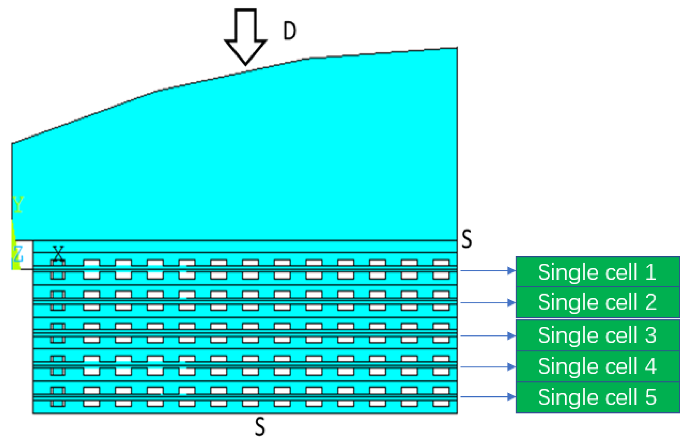
4.1. Evaluation of the Contact Pressure Distribution in PEMFC Stack

In order to evaluate the mechanical contact behavior of the fuel cells in a PEMFC stack, the mean μ, the standard deviation σ and the variation coefficient c v of the contact pressure are defined as follows:
μ = i = 1 i = N P i N
σ = i = 1 i = N ( P i μ ) 2 N
c v = σ μ
where P i is the contact pressure on the multiple interfaces between the BPP and MEA of each cell, and N is the total number of contact elements of the BPP and MEA.
In this study, the variation coefficient c v of the contact pressure is defined to evaluate the uniformity of the contact pressure distribution in the PEMFC stack with the key dimensional parameters of the cross-sectional shape of the endplate.

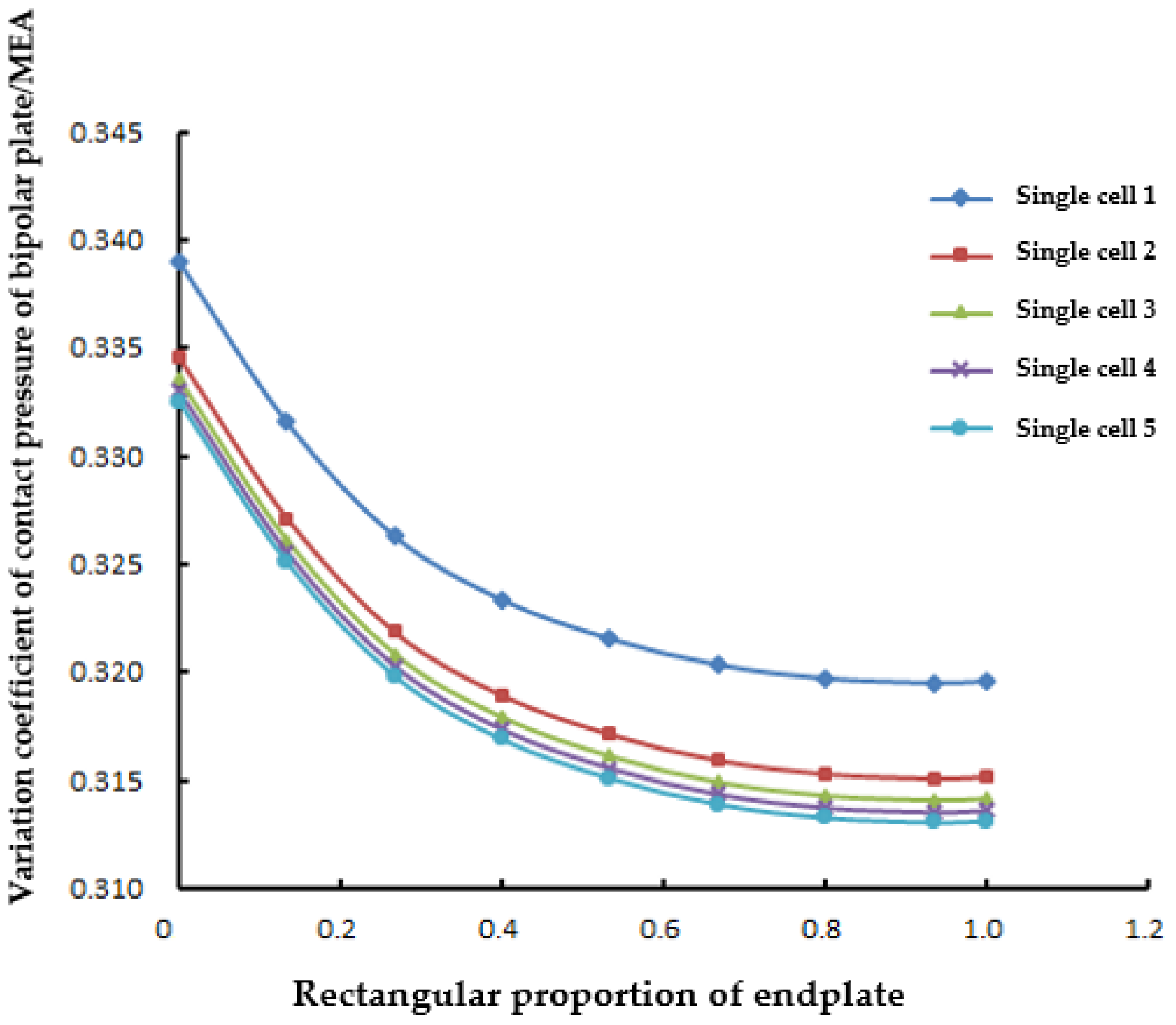
4.2. Effects of the Cross-Sectional Rectangular Proportion of the Endplate

The cross-sectional rectangular proportion of the endplate is defined as the ratio of the area of the rectangular part to the entire cross-sectional area of the endplate. As shown in Figure 2, the entire cross-sectional area of the endplate can be approximately regarded as the total areas of the rectangle and triangle. Therefore, the cross-sectional rectangular proportion of the endplate can be represented by Equation (16):
ρ h 2 h l h l + h m
where ρ h is the cross-sectional rectangular proportion of the endplate.
As shown in Figure 2, the high thickness of endplate h m remains the same, and the low thickness of the endplate h l increases from 0 to h m for different cross-sectional rectangular proportions of the endplate. Figure 7 shows the variation coefficient c v of the contact pressure obtained using the FEA model for each cell in the PEMFC stack with different cross-sectional rectangular proportions of the endplate.
It can be found from Figure 7 that the variation coefficient of the contact pressure decreases with the cross-sectional rectangular proportion of the endplate until ρ h = 0.8 , and then, the variation coefficient of the contact pressure is nearly constant. Therefore, the low thickness of the endplate h l = 2 3 h m for a highly uniform contact pressure distribution as well as maintaining the high-volume-specific power density of the PEMFC stack.

4.3. Effects of the Curvature Radius of the Cross-Sectional Shape of the Endplate

As shown in Figure 2, r 1 , r 2 and r 3 are the curvature radii corresponding to arcs c 1 , c 2 and c 3 with the corresponding centers o 1 , o 2 and o 3 . Since the curvature radius can affect the clamping force and the endplate deformation, the contact pressure distribution in the PEMFC stack is evaluated with different curvature radii. To facilitate this evaluation, the curvature radius of the circular arc is normalized to the relative curvature radius r g based on the curvature radius of the circular arc corresponding to the center o 2 .
r g = r j r 2
where r j is the curvature radius of the arc with the center between o 1 and o 3 ; r 2 is the curvature radius of the arc whose center is at o 2 , and o 2 is on the center line of the cross-section, as shown in Figure 2.
The variation coefficient of the contact pressure for each cell in the PEMFC stack with different relative curvature radii is shown in Figure 8 for when r g is 0.1, 0.5, 1, 1.5, 2 and 3.
It can be found from Figure 8 that the variation coefficient of the contact pressure increases with the curvature radius of the arc, which indicates that the effect of the curvature radius of the arc is negative to the uniformity of the contact pressure distribution. A small curvature radius of the cross-section is beneficial to the uniform contact pressure distribution.
Moreover, for the first and second single cells close to the end plate, the variation coefficient changes slightly when r g increases from 0.1 to 0.5, but for cells 3, 4 and 5, as shown in Figure 3, close to the center of the PEMFC stack, the variation coefficient of the contact pressure changes significantly with the curvature radius. This indicates that the curvature radius of the arc has an important influence on the internal cells of the PEMFC stack.

5. Conclusions

In this study, an equivalent beam model was established for the optimization of the Belleville spring positions and numbers in order to minimize the deformation of the endplate for a uniform contact pressure distribution of a PEMFC stack. Based on this, an FEA model with 10 cells considering the multiple interfaces between the BPPs and MEAs was established to optimize the key dimensional parameters of the cross-sectional shape of the endplate as well as the evaluation of the contact pressure distribution in the PEMFC stack. The effects of the cross-sectional rectangular proportion and curvature radius of the endplate were discussed. The presented equivalent beam and FEA models are effective and desirable in designing and optimizing the endplate with Belleville springs in a PEMFC stack assembly, which can increase the uniformity of the pressure distribution in the stack and further increase the efficiency of the PEMFC stack.
Firstly, an effective equivalent beam model for the endplate clamped by four steel belts with two, three and four groups of Belleville springs in a PEMFC stack was proposed, and the deformation of the endplate was illustrated in order to minimize the deformation of the endplate as well as the uniform contact pressure distribution in the PEMFC stack. Since excessive assembly forces may lead to the failure of the Belleville springs in performing their function in a fuel cell stack, it should be noted that the assembly forces should ensure that the Belleville springs are within their allowable operating range.
Secondly, the optimal position of the two, three and four groups of Belleville springs on the endplate with different numbers of Belleville springs is significant in minimizing the deformation of the endplate, which is favorable to the uniform contact pressure distribution in the PEMFC stack. Moreover, the external position of the Belleville springs on the endplate is more important than the internal position of the Belleville springs, which should be carefully designed during the assembly of a PEMFC stack.
Thirdly, the cross-sectional rectangular proportion of the endplate is significant for the distribution of the contact pressure, and the high cross-sectional rectangular proportion of the endplate can minimize the non-uniformity of the contact pressure in the PEMFC stack.
Finally, the curvature radius of the arc in the cross-sectional endplate also affects the contact pressure distribution in the PEMFC stack; however, its effect is negative, and a small curvature radius of the cross-section is beneficial to the uniform contact pressure distribution.
The results are significant in providing a design direction for PEMFC stacks integrated with multiple groups of Belleville springs and steel belts.

Author Contributions

Conceptualization, Z.Z. and S.H.; methodology, Z.Z.; software, H.R., X.Z. and T.Y.; validation, Z.Z., J.Z. and S.J.; resources, T.Z. and J.Z.; writing—original draft preparation, Z.Z. and H.R.; writing—review and editing, Z.Z. and B.D.; project administration, Z.Z.; funding acquisition, Z.Z. All authors have read and agreed to the published version of the manuscript.

Funding

This research was funded by the Natural Science Foundation of Shanghai, grant number 22ZR1466800.

Institutional Review Board Statement

Not applicable.

Informed Consent Statement

Not applicable.

Data Availability Statement

Not applicable.

Conflicts of Interest

The authors declare no conflict of interest.

References

  1. Olabi, A.G.; Wilberforce, T.; Abdelkareem, M.A. Fuel cell application in the automotive industry and future perspective. Energy 2021, 214, 118955. [Google Scholar] [CrossRef]
  2. Luo, Y.; Wu, Y.H.; Li, B.; Mo, T.D.; Li, Y.; Feng, S.P.; Qu, J.K.; Chu, P.K. Development and application of fuel cells in the automobile industry. J. Energy Storage 2021, 42, 103124. [Google Scholar] [CrossRef]
  3. Alaswad, A.; Baroutaji, A.; Achour, H.; Carton, J.; Makky, A.A.; Olabi, A.G. Developments in fuel cell technologies in the transport sector. Int. J. Hydrogen Energy 2016, 41, 16499–16508. [Google Scholar] [CrossRef] [Green Version]
  4. Zeng, T.; Zhang, C.; Hao, D.; Cao, D.; Chen, J.; Chen, J.; Li, J. Data-driven approach for short-term power demand prediction of fuel cell hybrid vehicles. Energy 2020, 208, 118319. [Google Scholar] [CrossRef]
  5. Ajanovic, A.; Haas, R. Prospects and impediments for hydrogen and fuel cell vehicles in the transport sector. Int. J. Hydrogen Energy 2021, 46, 10049–10058. [Google Scholar] [CrossRef]
  6. Xu, X.; Zhao, J.; Zhao, J.W.; Shi, K.; Dong, P.; Wang, S.; Liu, Y.; Guo, W.; Liu, X. Comparative study on fuel saving potential of series-parallel hybrid transmission and series hybrid transmission. Energy Conv. Manag. 2022, 252, 114970. [Google Scholar] [CrossRef]
  7. Acar, C.; Dincer, I. The potential role of hydrogen as a sustainable transportation fuel to combat global warming. Int. J. Hydrogen Energy 2020, 45, 3396–3406. [Google Scholar] [CrossRef]
  8. Wang, Y.; Diaz, D.F.R.; Chen, K.S.; Wang, Z.; Adroher, X.C. Materials, technological status, and fundamentals of PEM fuel cells—A review. Mater. Today 2020, 32, 178–203. [Google Scholar] [CrossRef]
  9. Sun, L.; Shen, J.; Hua, Q.; Lee, K.Y. Data-driven oxygen excess ratio control for proton exchange membrane fuel cell. Appl. Energy 2018, 231, 866–875. [Google Scholar] [CrossRef]
  10. Sun, L.; Jin, Y.; You, F. Active disturbance rejection temperature control of open-cathode proton exchange membrane fuel cell. Appl. Energy 2020, 261, 114381. [Google Scholar] [CrossRef]
  11. Niu, T.; Huang, W.; Zhang, C.; Zeng, T.; Chen, J.; Li, Y.; Liu, Y. Study of degradation of fuel cell stack based on the collected high-dimensional data and clustering algorithms calculations. Energy AI 2022, 10, 100184. [Google Scholar] [CrossRef]
  12. Wu, C.W.; Zhang, W.; Han, X.; Zhang, Y.X.; Ma, G.J. A systematic review for structure optimization and clamping load design of large proton exchange membrane fuel cell stack. J. Power Sources 2020, 476, 228724. [Google Scholar] [CrossRef]
  13. Qiu, D.K.; Peng, L.F.; Yi, P.Y.; Lehnert, W.; Lai, X.M. Review on proton exchange membrane fuel cell stack assembly: Quality evaluation, assembly method, contact behavior and process design. Renew. Sustain. Energy Rev. 2021, 152, 111660. [Google Scholar] [CrossRef]
  14. Yan, X.H.; Lin, C.; Zheng, Z.F.; Chen, J.R.; Wei, G.H.; Zhang, J.L. Effect of clamping pressure on liquid-cooled PEMFC stack performance considering inhomogeneous gas diffusion layer compression. Appl. Energy 2020, 258, 114073. [Google Scholar] [CrossRef]
  15. Peng, L.F.; Shao, H.; Qiu, D.K.; Yi, P.Y.; Lai, X.M. Investigation of the non-uniform distribution of current density in commercial-size proton exchange membrane fuel cells. J. Power Sources 2020, 453, 227836. [Google Scholar] [CrossRef]
  16. Yang, D.; Hao, Y.; Li, B.; Ming, P.; Zhang, C. Topology optimization design for the lightweight endplate of proton exchange membrane fuel cell stack clamped with bolts. Int. J. Hydrogen Energy 2022, 47, 9680–9689. [Google Scholar] [CrossRef]
  17. Shinde, U.; Koorata, P.K. Numerical investigation on the sensitivity of endplate design and gas diffusion material models in quantifying localized interface and bulk electrical resistance. Int. J. Hydrogen Energy 2021, 46, 17358–17373. [Google Scholar] [CrossRef]
  18. Asghari, S.; Shahsamandi, M.H.; Khorasani, M.R.A. Design and manufacturing of end plates of a 5 kW PEM fuel cell. Int. J. Hydrogen Energy 2010, 35, 9291–9297. [Google Scholar] [CrossRef]
  19. Habibnia, M.; Shirkhani, M.; Tamami, P.G. Optimization of proton exchange membrane fuel cell’s end plates. SN Appl. Sci. 2020, 2, 1380. [Google Scholar] [CrossRef]
  20. CKumar, G.C.; Baligidad, S.M.; Maharudresh, A.C.; Chetan, T.N.; Dayanand, N. Experimental analysis on stacking of Belleville spring. Mater. Today Proc. 2022, 50, 1547–1552. [Google Scholar] [CrossRef]
  21. Alizadeh, E.; Barzegari, M.M.; Momenifar, M.; Ghadimi, M.; Saadat, S.H.M. Investigation of contact pressure distribution over the active area of PEM fuel cell stack. Int. J. Hydrogen Energy 2016, 41, 3062–3071. [Google Scholar] [CrossRef]
  22. Zhang, W.; Cho, C.; Piao, C.H.; Choi, H. Sobol’s sensitivity analysis for a fuel cell stack assembly model with the aid of structure-selection techniques. J. Power Sources 2016, 301, 1–10. [Google Scholar] [CrossRef]
  23. Zhou, Z.H.; Qiu, D.K.; Zhai, S.; Peng, L.F.; Lai, X.M. Investigation of the assembly for high-power proton exchange membrane fuel cell stacks through an efficient equivalent model. Appl. Energy 2020, 277, 115532. [Google Scholar] [CrossRef]
  24. Lin, P.; Zhou, P.; Wu, C.W. Multi-objective topology optimization of end plates of proton exchange membrane fuel cell stacks. J. Power Sources 2011, 196, 1222–1228. [Google Scholar] [CrossRef]
  25. Liu, B.; Wei, M.Y.; Ma, G.J.; Zhang, W.; Wu, C.W. Stepwise optimization of endplate of fuel cell stack assembled by steel belts. Int. J. Hydrogen Energy 2016, 41, 2911–2918. [Google Scholar] [CrossRef]
  26. Zhang, Z.M.; Zhang, J.; Zhang, T. Endplate Design and Topology Optimization of Fuel Cell Stack Clamped with Bolts. Sustainability 2022, 14, 4730. [Google Scholar] [CrossRef]
  27. Yu, H.N.; Kim, S.S.; Suh, J.D.; Lee, D.G. Composite endplates with pre-curvature for PEMFC (polymer electrolyte membrane fuel cell). Compos. Struct. 2010, 92, 1498–1503. [Google Scholar] [CrossRef]
  28. Yu, Y.H.; Lim, J.W.; Lee, D.G. Composite sandwich endplates with a compliant pressure distributor for a PEM fuel cell. Compos. Struct. 2015, 119, 505–512. [Google Scholar] [CrossRef]
  29. Alizadeh, E.; Ghadimi, M.; Barzegari, M.M.; Momenifar, M.; Saadat, S.H.M. Development of contact pressure distribution of PEM fuel cell’s MEA using novel clamping mechanism. Energy 2017, 131, 92–97. [Google Scholar] [CrossRef]
  30. Barzegari, M.M.; Ghadimi, M.; Momenifar, M. Investigation of contact pressure distribution on gas diffusion layer of fuel cell with pneumatic endplate. Appl. Energy 2020, 263, 114663. [Google Scholar] [CrossRef]
  31. Chung, T.T.; Lin, C.T.; Shiu, H.R. Mechanical design and analysis of a proton exchange membrane fuel cell stack. J. Chin. Inst. Eng. 2016, 39, 353–362. [Google Scholar] [CrossRef]
  32. Gere, J.M.; Goodno, B.J. Mechanics of Materials, 8th ed.; Cengage Learning: Boston, MA, USA, 2012; pp. 730–798. [Google Scholar]
  33. Zhang, J.; Hu, Y.; Han, C.; Zhang, H. Stress response and contact behavior of PEMFC during the assembly and working condition. Int. J. Hydrogen Energy 2021, 46, 30467–30478. [Google Scholar] [CrossRef]
Figure 1. Equivalent beam model of Belleville springs, endplate and 4 steel clamping belts: (a) 2 groups of Belleville springs; (b) 3 groups of Belleville springs; (c) 4 groups of Belleville springs.
Sustainability 14 15928 g001
Figure 2. Cross-sectional shape of the endplate and its key influencing dimensional parameters.
Sustainability 14 15928 g002
Figure 3. A 2D quarter symmetric FEA model of the fuel cell stack with an arc endplate.
Sustainability 14 15928 g003
Figure 4. The deformation of the equivalent beam (2 groups of Belleville springs).
Sustainability 14 15928 g004
Figure 5. The deformation of the equivalent beam (3 groups of Belleville springs).
Sustainability 14 15928 g005
Figure 6. The deformation of the equivalent beam (4 groups of Belleville springs).
Sustainability 14 15928 g006
Figure 7. The variation coefficient of the contact pressure of each cell in the PEMFC stack with different cross-sectional rectangular proportions of the endplate.
Sustainability 14 15928 g007
Figure 8. The variation coefficient of the contact pressure in the PEMFC stack with the different curvature radii.
Sustainability 14 15928 g008
Table 1. Dimensions of the components in the PEMFC stack.
PartLength/mmWidth/mmThickness/mm
Endplate31017015
Collector plate3001602
BPP3001602
Sealant2941560.625
MEA3001600.5
Table 2. Material properties of the components in the PEMFC stack [33].
PartMaterialElasticity Modulus/MPaPoisson’s Ratio
EndplateAluminum alloy70,0000.3
Collector plateCopper108,0000.33
BPPGraphite10,0000.25
SealantRubber50.49
MEAComposite210.1
Publisher’s Note: MDPI stays neutral with regard to jurisdictional claims in published maps and institutional affiliations.

