Geometric Recognition of Moving Objects in Monocular Rotating Imagery Using Faster R-CNN


1
Department of Civil and Construction Engineering, National Taiwan University of Science and Technology, Taipei 106, Taiwan
2
Department of Civil Engineering, National Taiwan University, Taipei 106, Taiwan
3
Land Administration Department, Yunlin County Government, Yunlin 640, Taiwan
4
Department of Civil Engineering, and Innovation and Development Center of Sustainable Agriculture, National Chung Hsing University, Taichung 402, Taiwan
5
Pervasive AI Research (PAIR) Labs, Hsinchu 300, Taiwan
*
Author to whom correspondence should be addressed.
Remote Sens. 2020, 12(12), 1908; https://0-doi-org.brum.beds.ac.uk/10.3390/rs12121908
Submission received: 1 May 2020
/
Revised: 8 June 2020
/
Accepted: 8 June 2020
/
Published: 12 June 2020
(This article belongs to the Special Issue Image Processing and Analysis: Trends in Registration, Data Fusion, 3D Reconstruction and Change Detection)
Abstract
:Moving object detection and tracking from image sequences has been extensively studied in a variety of fields. Nevertheless, observing geometric attributes and identifying the detected objects for further investigation of moving behavior has drawn less attention. The focus of this study is to determine moving trajectories, object heights, and object recognition using a monocular camera configuration. This paper presents a scheme to conduct moving object recognition with three-dimensional (3D) observation using faster region-based convolutional neural network (Faster R-CNN) with a stationary and rotating Pan Tilt Zoom (PTZ) camera and close-range photogrammetry. The camera motion effects are first eliminated to detect objects that contain actual movement, and a moving object recognition process is employed to recognize the object classes and to facilitate the estimation of their geometric attributes. Thus, this information can further contribute to the investigation of object moving behavior. To evaluate the effectiveness of the proposed scheme quantitatively, first, an experiment with indoor synthetic configuration is conducted, then, outdoor real-life data are used to verify the feasibility based on recall, precision, and F1 index. The experiments have shown promising results and have verified the effectiveness of the proposed method in both laboratory and real environments. The proposed approach calculates the height and speed estimates of the recognized moving objects, including pedestrians and vehicles, and shows promising results with acceptable errors and application potential through existing PTZ camera images at a very low cost.

1. Introduction
In the field of computer vision, detecting and tracking moving objects has been widely studied for decades. A survey of the challenges and the latest methods of moving object detection in video sequences captured by a moving camera is presented in [1]. Closed-Circuit Televisions (CCTVs) provide a large number of images for video surveillance that involves various machine learning technologies [2]. Emerging applications in artificial intelligence, for example, [3,4,5,6,7,8,9], attract research attention for three-dimensional (3D) information acquisition from imagery to recognize objects and also to perceive their behaviors. Nevertheless, to robustly detect, track, and identify moving objects is still a challenge since a large number of variables and the possible geometric and dynamic ambiguities are involved in the computation [10,11,12,13]. To precisely separate moving objects from image backgrounds, existing methods, such as optical flow, as well as segmenting-based and supervised classifier methods, usually assume that a camera has been nearly stationary or the background was priori known and modeled [14,15,16,17,18,19,20]. The segmenting-based methods, such as mean shift clustering, graph-cuts, and active contours, divide the images into perceptually similar regions. Supervised classification methods, such as support vector machine, neural networks, and adaptive boosting techniques, are trained to detect the features of the objects [21]. Recently, a detector-agnostic procedure was developed by integrating both unsupervised (background subtraction) and supervised (deep learning convolutional neural networks (CNN)) techniques to extract the detected and verified targets through the fusion and data association steps [2]. In addition, optical flow approaches calculate the image optical flow field and conduct clustering according to the flow distribution of images. However, the computational complexity and sensitiveness to noise make it less reliable for real-time demanding applications [22,23]. By contrast, a more intuitive method is the background subtraction method in which algorithms can be categorized into recursive and non-recursive methods [24]. These algorithms can provide more comprehensive object information by finding the variations in the image background model provided that the precise background has been known [25,26,27]. However, these methods have less robustness to external interference such as illumination change and shadow effects. In addition, 3D scene flow has been introduced to form a dense 3D motion field for object detection, but stereo or multiple camera configurations are typically required to obtain depth information of the scene [28,29].
Pan-tilt-zoom (PTZ) camera networks have an important role in surveillance systems, especially traffic security for detecting moving objects, such as pedestrians and vehicles on roads. Stationary and rotating PTZ cameras are able to construct the coverage of wide and geometrically complex scenes with a relatively small number of sensors. Most of the above-mentioned moving object detection techniques can be applied to PTZ cameras. To detect satisfactory foreground objects, most methods assume that the camera and image background are static [30]. In cases where a camera bears arbitrary motion variation or the background is quite complex (e.g., illumination change and large objects moving in the background), the accuracy and reliability degenerate dramatically [31,32]. Numerous studies have demanded that a camera certainly contained translational and rotational or merely translational variation to recover the camera motion using structure from motion (SfM) technique and determined the 3D positions of detected objects using stereo or multiple views [11]. However, the motion prerequisite for SfM conflicts with a stationary and rotating camera configuration that is inadequate for the focus of this study.
Object recognition has been well explored for years, for example, [33,34,35,36], and can search the object position in the image and identify its category to assist in the calculation of the subsequent geometric information. Nevertheless, these methods are being potentially replaced by learning-based techniques, which are a revival of the classic artificial intelligence technique of neural networks, for example, [37,38,39,40,41,42], and thus are leveraged in this study. Neural network-based solutions to moving object detection PTZ camera images have received considerable attention due to their effectiveness and efficiency [43]. The comparison between various network structures have been studied in the literature. Faster region-based convolutional neural network (Faster R-CNN), one of the deep-learning-based approaches, has been reported to significantly reduce the running time of object detection with an acceptable accuracy [2,44]. In this paper, Faster R-CNN is used to identify multiple classes from the detected moving objects due to its ability to lower computation costs and its high accuracy. In addition, in contrast to dashboard cameras equipped on cars, surveillance cameras mostly shoot from a commanding height down to the ground, and therefore have a great opportunity to observe the depth of detected objects. The previous researches have often ignored the deviation of the actual height estimation of the objects when the object possessed a depth difference. Contrary to previous literature that has considered detected objects to be two-dimensional (2D) objects, this study adds an aspect from close-range photogrammetry to computer vision technology in order to reveal 3D attributes of detected objects. This study focuses on the spatial information processing of object geometry estimation in PTZ camera images under non-ideal imaging geometry for calculating the depth of the detected object resulting in a better estimation of object height for object identification.
This paper contributes a scheme to execute moving object recognition and further derives the geometric attributes from a single stationary and rotating PTZ camera configuration. Considering that both the foreground and background change while the camera is rotating, the scheme begins with the rectification of camera motion and proceeds with the moving object detection and identification by leveraging background subtraction and recognition techniques. Finally, the foreground pixels of the moving objects are refined and used to observe geometric attributes of each object using a combination of single- and multi-view solutions. With an assumption that all moving objects should locate on a known plane, the geometric attributes of the objects are determined from a monocular camera configuration, providing important clues for further intelligent applications. In addition, the proposed method is implemented on street-view images acquired using a SAMPO PTZ camera (Sampo Corporation, Taoyuan, Taiwan) in a stationary and rotating configuration, context (COCO) dataset, and KITTI dataset [45] for performance evaluation.
2. Methodology
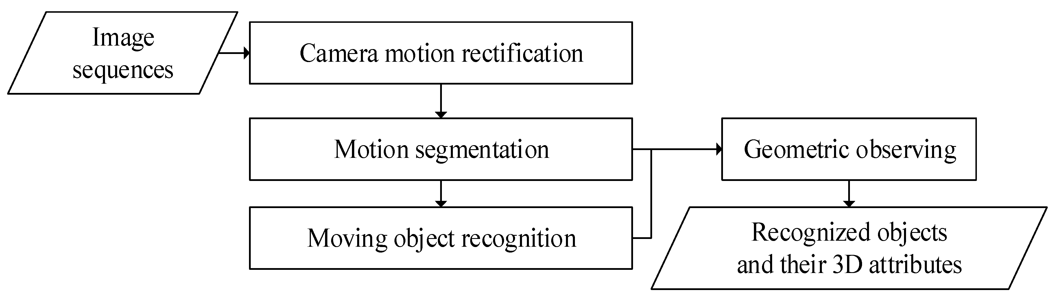
The proposed scheme was comprised of the following four modules to identify, track, and perceive moving objects: (1) camera motion rectification, (2) motion segmentation, (3) moving object recognition, and (4) geometric observing. The block diagram of the proposed scheme is shown in Figure 1.
2.1. Camera Motion Rectification
Since the movements of a rotating camera critically degenerate the accuracy and reliability of the motion segmentation, the proposed scheme begins with rectification to eliminate the camera motion by estimating the camera poses at each epoch, which is the critical process to find actual moving objects. Referring to the evaluation of state-of-the-art image features, speeded up robust features (SURF) method [46] has shown good accuracy regarding generic invariance properties. Although no best feature descriptor can tackle all kinds of deformation at present, SURF has shown its effectiveness and efficiency. Thus, SURF correspondences refined by random sample consensus (RANSAC) [47] were employed to construct the essential matrix for the relative camera pose estimation. The object function describing epipolar geometry for estimating camera poses can be read as:
where and indicate the image coordinates in left and right images, respectively and is the matrix conveying interior parameters of the camera. , an essential matrix, which can be expressed as Equation (2), can be solved linearly and used as approximations for nonlinear least squares adjustment [48].
where , , and are the eigenvalues derived from .
where , , , , and denote an observation vector, a residual vector, a constant vector, unknowns, and a weight matrix, respectively. Rearranging Equation (2) leads to the following form:
where are discrepancy vectors. Thus, the unknowns can be derived by Equation (5), and a posteriori standard deviation of unit weight can be computed via Equation (6), in which is the number of degrees of freedom (redundancy) as follows:
Consequently, the photo coordinate system of the current image frame can be transformed into the coordinate system of a previous one via the relative camera poses. On the basis of the same coordinate system, the average movements between feature correspondences are estimated by:
where ( indicates the average translation between corresponding feature points. (,) and (,) are the photo coordinates of corresponding features in the query and reference frames, respectively. Thus, the rectified photo coordinates of the current frame with respects to reference one can be derived:
where ( indicates the rectified photo coordinates which are then transformed to the image coordinates for transmitting their color attributes as follows:
where (, ) indicates the rectified image coordinates; (, ) is the principle point of the reference frame, and the (,) and (, ) represent the number of pixels in x and y directions and the size of image frames, respectively. Finally, the original spectrum information can be conveyed to the rectified images.
2.2. Motion Segmentation
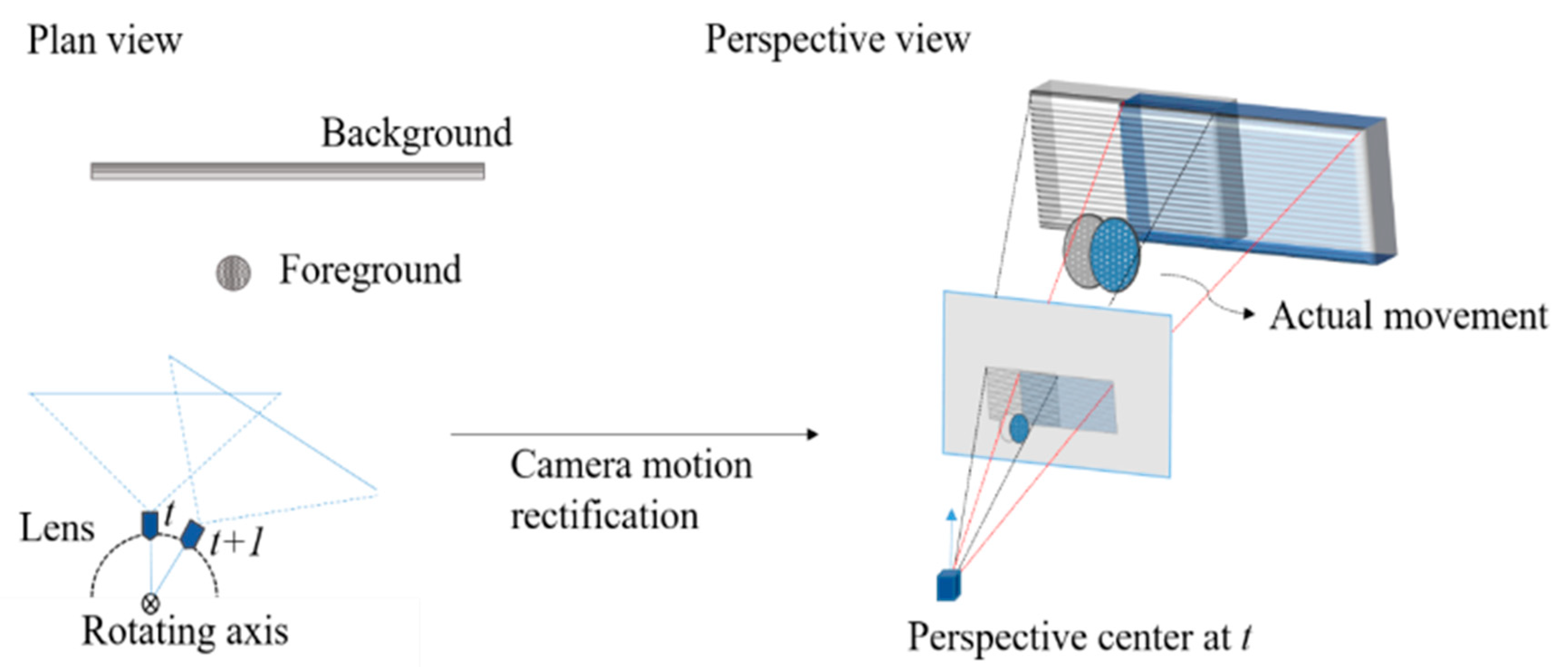
Since this study applied a stationary and rotating camera configuration, the background and foreground changed simultaneously. If the foreground object and the camera moved in the same direction, the camera motion would counteract the movement of the object. On the contrary, the object movement would be magnified if the object and the camera moved in opposite directions. Therefore, as shown in Figure 2, without eliminating the interference of camera motion, it could lead to false positives of motion segmentation and a misinterpretation of the moving behavior.
The segmentation process is to retrieve the actual moving objects from consecutive image frames, which was realized by a recursive background subtraction technique in this study. The red, green, and blue (RGB) color space can be converted to hue, saturation, and intensity (HSI) space to ease the lighting influence and to enhance segmentation quality.
where H, S, and I indicate hue, saturation, and intensity, whereas R, G, and B indicate the values of the three-color channels. In addition, an exponent subtraction factor based on saturation to distinguish moving objects from the background can be read as:
where indicates the i-th image input, is treated as the reference frame. is the subtraction factor, and is the exponent. A pixel is deemed as the foreground if the subtracting result is larger than a threshold that can be set adaptively according to the 3 of the average difference.
where FG indicates the foreground; μ and σ are the mean and the standard deviation, respectively. Furthermore, to eliminate salt-and-pepper noise, a median filter was used to polish the foreground [49].
2.3. Moving Object Recognition
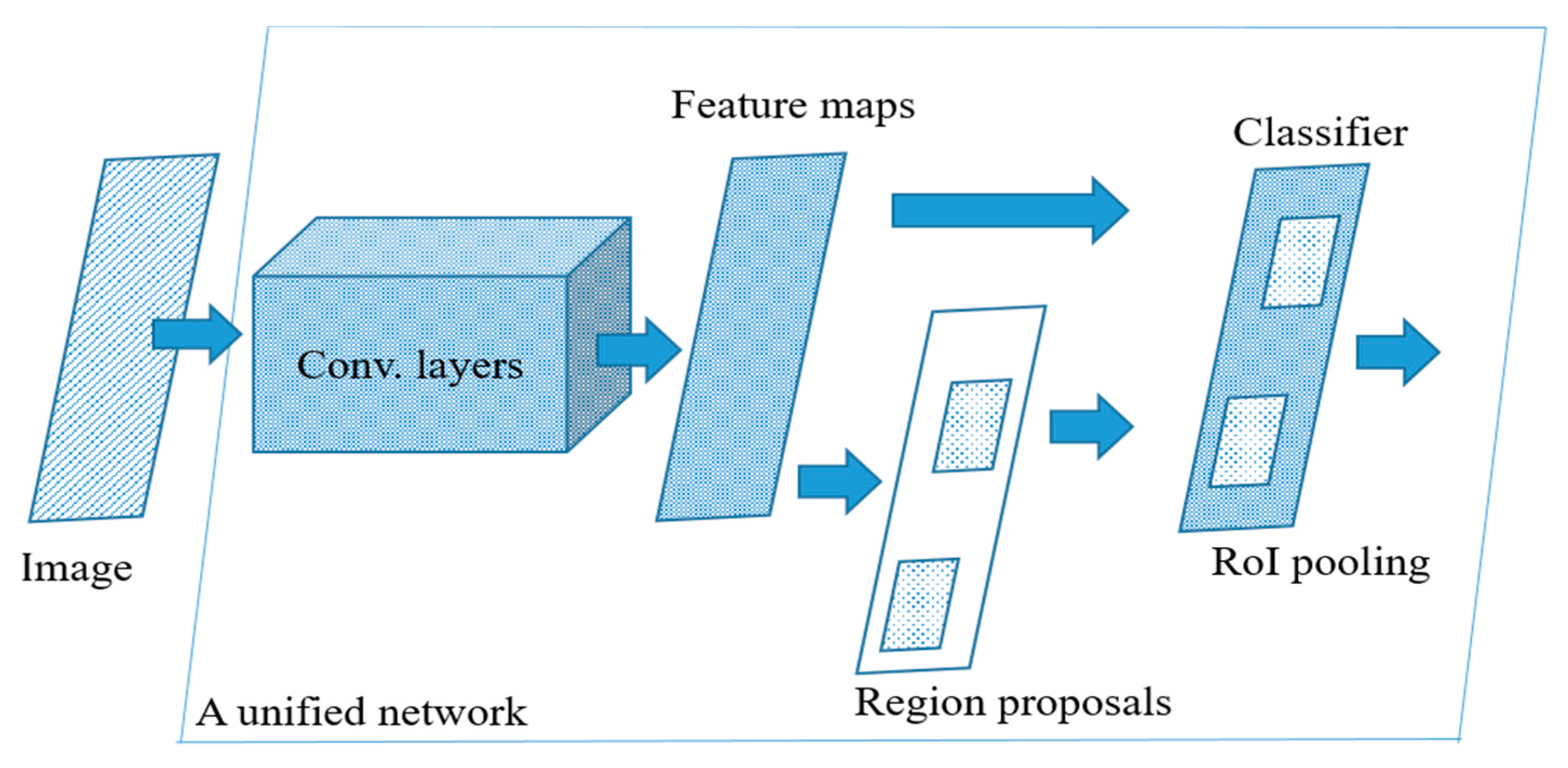
To identify multiple classes from the detected moving objects, the model combining Faster R-CNN [41] with neural architecture search (NAS) [50] was leveraged in this study. In Figure 3, Faster R-CNN integrates feature extraction, region proposal, classification, and bounding box regression into a unified network, and reveals the best recognition accuracy but the lowest efficiency. The details of the recognition model can be referred to in [41].
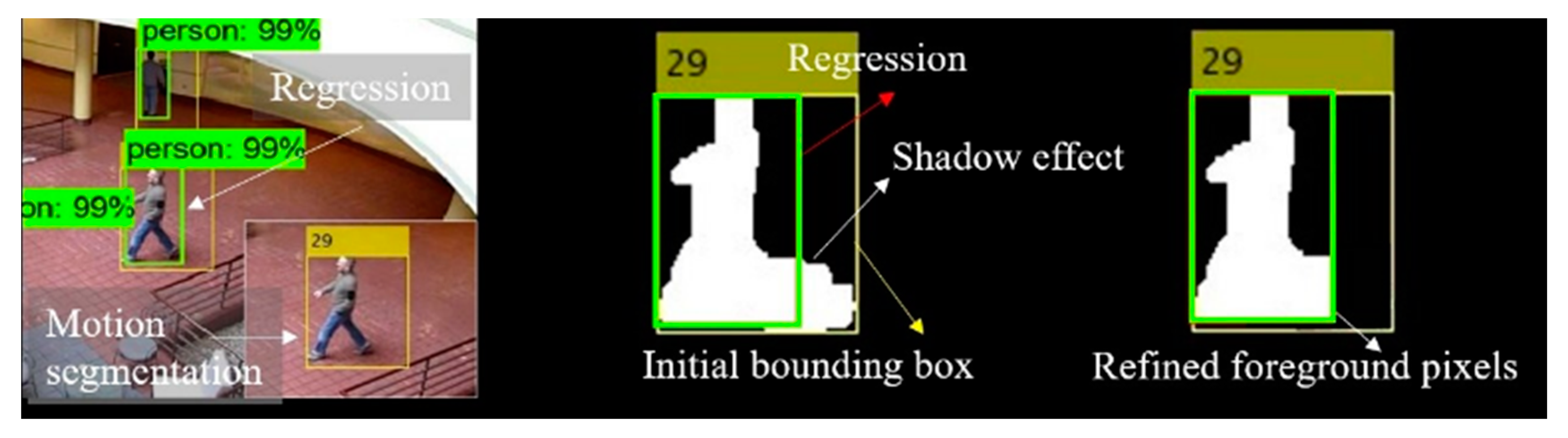
It is worthwhile noting that the process of bounding box regression in this model can give precise estimates of the object regions since the region proposals are regressed based on the convolutional neural network. Therefore, the initial foreground pixels determined by the motion segmentation can be refined based on the regressive bounding boxes. The foreground pixels that fall outside the bounding should be excluded from the subsequent geometric computation process. As shown in Figure 4, the initial foreground pixels are determined by the yellow bounding boxes and can be further rectified by the regressive green boxes. The lighting or shadow interference was eased, and thus more reliable geometric estimation could be achieved.
2.4. Geometric Observing
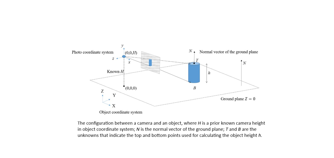
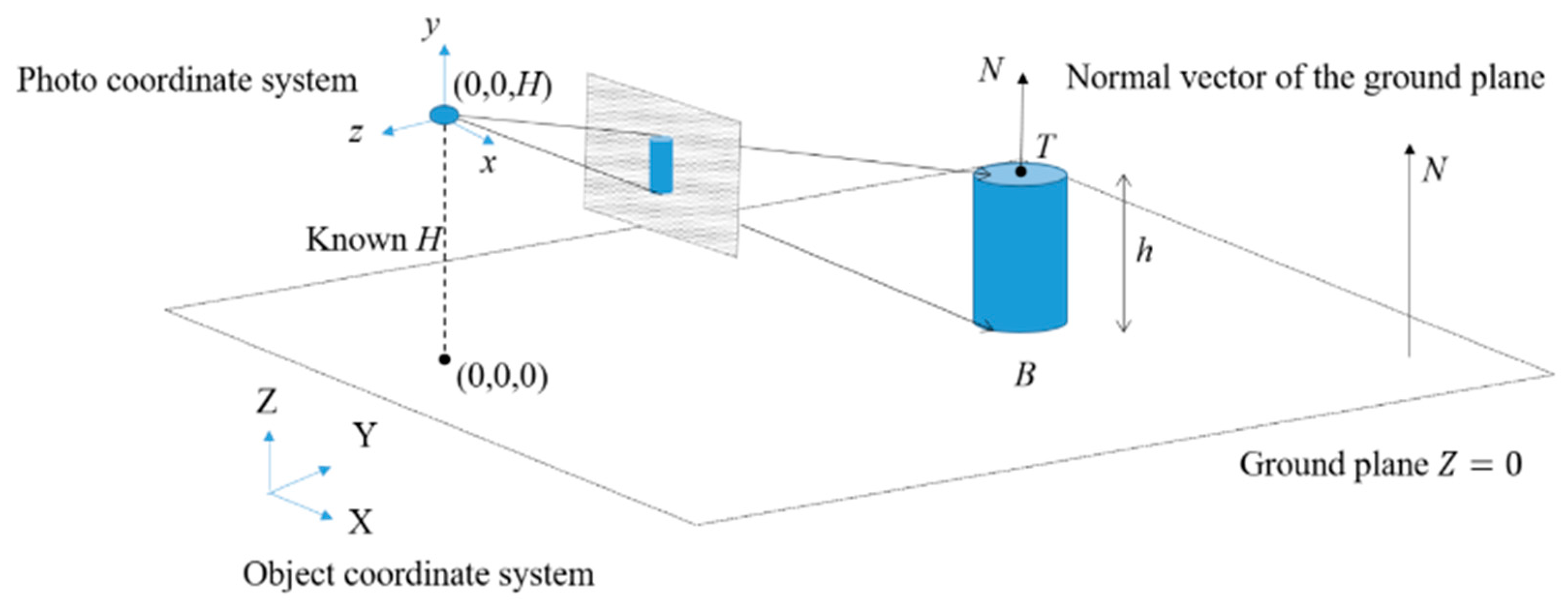
This step collects the 3D geometric attributes of the recognized moving objects with respect to moving trajectories, object heights, and moving velocity. The locations of the moving objects in 3D space need to be first determined. Most existing methods, such as visual simultaneous localization and mapping (SLAM) and visual odometry, for example, [51,52], usually deal with stereo- or multi-view images for the better intersecting geometry of 3D positioning. However, considering a single stationary and rotating camera configuration, these methods are not suitable even though slight motion and shift exist among the camera poses due to the deviation between the perspective center and the rotating axis. In addition, considering that only slight translational discrepancy exists between two perspectives centers at different timestamps, multiple view solutions would raise problems in dealing with weak intersecting geometry. In view of this, in this study, we determined the 3D locations of objects by combining single and multiple view solutions. The initial position was estimated in a single view manner, and then the estimate was treated as approximations to stabilize the computation of multiple view estimation. For this purpose, the first image frame was selected to define the reference coordinate system, and a ground plane where all objects should move on this plane was given. As shown in Figure 5, the image ray constructed by the camera center and the image point of B was used to intersect with the ground plane for determining the location B of the object.
The image ray of a point can be described by the well-known collinearity equation as:
where (,,) and (,,) indicate the 3D coordinates of the camera and objects, respectively; (, ) is the image coordinates; and (, ,) is the interior orientation parameters. In cases that the ground plane is expressed as , the bottom point of the object can be solved based on the simultaneous equations of the collinearity and plane formulae. In fact, the height of a moving object should be perpendicular to the ground, and the top point T of the object can be determined by solving the intersection of the image ray and the 3D line derived from the normal vector and the bottom point. Furthermore, to refine the positioning quality of the B and T, the estimates derived from the single view computation were treated as approximations for the multiple view estimation. The approximations stabilized the nonlinear calculation, even though the baselines between perspective centers of consecutive frames were relatively short. Finally, the refined T and B points were used to compute the object height, h. The bottom points of the object among frames describe its moving trajectory, and the velocity over time can be derived as well. It should be noted that the lowest and highest pixels crossing the object centroid and perpendicular to the ground plane are deemed to be the bottom and top points in this study.
Apart from determining the coordinate estimates, in this study, we further assessed the accuracy of the estimation from the related observations based on the theory of error propagation. Let and indicate the accuracy of the image coordinates of a point, , , and report the accuracy of camera position; and and denote the accuracy of image orientation parameters. The accuracy of the unknown X and Y of a point can be acquired as follows:
where indicates the variance-covariance matrix of the point coordinates, is the coefficient matrix with respect to the observations, and is the variance-covariance matrix of the observation. These matrixes can be read as:
In case that the accuracy of B and T points are computed, then, the quality of h can be estimated in a similar way. Let , the accuracy of B and T is and , respectively. Thus, the variance of h can be:
3. Results and Discussion
As mentioned above, in contrast to the existing methods designed for stationary or with motion prerequisites camera systems, this study concentrates on acquiring the geometric observations of moving objects detected from a stationary and rotating monocular camera. To evaluate the effectiveness of the proposed scheme quantitatively, an experiment with synthetic configuration is first conducted, and then a real-life data is used to verify the feasibility. In this study, the following three indices, namely recall, precision, and , are employed to assess the quality of foreground pixel detection:
3.1. Quantitative Evaluation with Synthetic Configuration
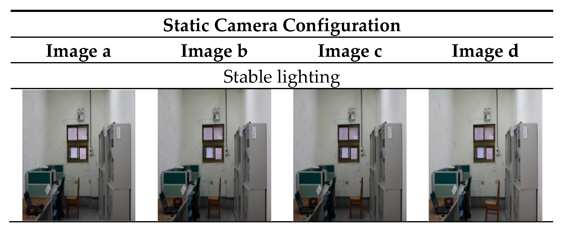
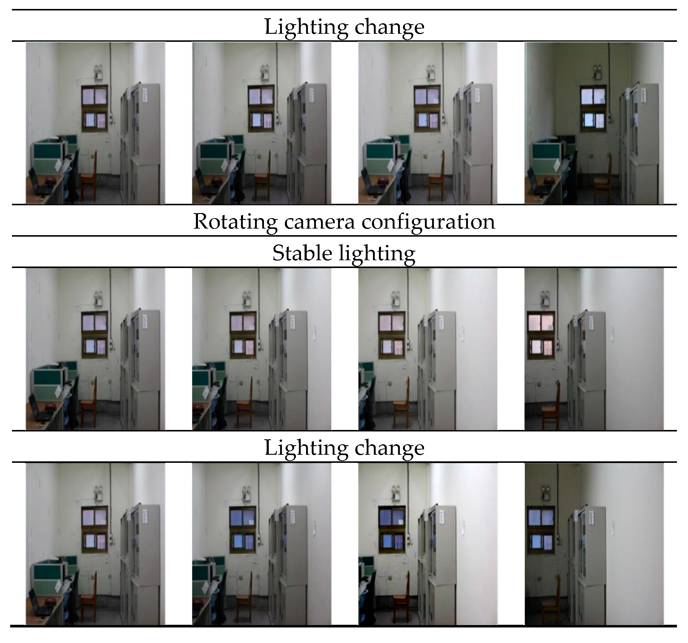
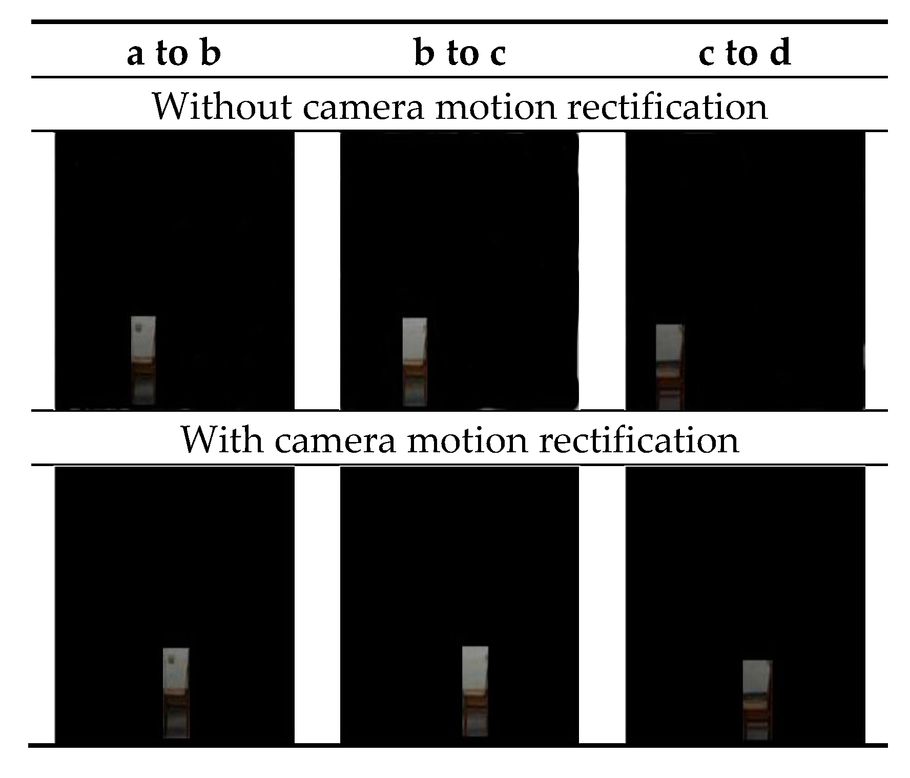
In this case, a calibrated Canon EOS 650D (Canon Inc., Tokyo, Japan) is used to acquire sequential images with a size of 5183 × 3456 pixels. To verify the effectiveness of the camera motion rectification, the background subtraction is implemented for images acquired by rotating and static camera configuration, respectively. To assess the robustness to illumination change, the simulation is realized in an indoor environment for the convenience of lighting control. A rigid chair is used to play the role of a moving object. The rotating angle of the camera is four degrees per step. The depth of this test field is 6.5 m. Figure 6 shows a fraction of the captured images under different lighting conditions, in which the image data captured by a static camera configuration are treated as the reference for the following assessment. Figure 7 shows the motion segments of the object obtained before and after camera motion rectification. Noticeably, without rectification, the camera motion counteracts the movement of the object when the foreground object and the camera move in the same direction. On the contrary, the object movement would be magnified if the object and the camera move in opposite directions. This would lead to false positives of motion segmentation and a misinterpretation of the moving behavior.
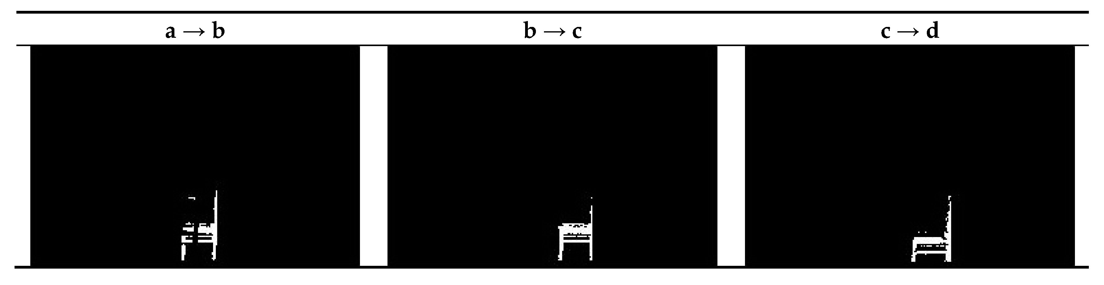
Figure 8 provides a visual inspection of the detected foreground object. Notably, with respect to the detected results, in all configurations of images a and b, there exist a gap in the middle of the chair. It is because parts of the moving object contain similar texture and are overlapped in the consecutive frames; the overlapped areas are regarded as background, and thus result in the gap.
Furthermore, a quantitative evaluation is given in Table 1 which provides insight into the effectiveness of the proposed method. The detection results obtained from the static and rotating camera configurations exhibit comparable quality regardless of the camera motion and the illumination change, proving the validity of the rectification. Although the recall rates of the rotating camera configuration are slightly lower than the stable one, the precision rates reveal that the rotating configuration yields more accurate detection on the contrary, which is also shown in the resulting aggregative indices. Moreover, the illumination change certainly affects the foreground determination, and therefore the recall rate of the rotating camera configuration with lighting change drops to 60% in images c and d. The proposed method yields satisfactory performance, achieving a level up to 0.90 in the aggregative index.
3.2. Street View Surveillance of a Rotating PTZ Camera
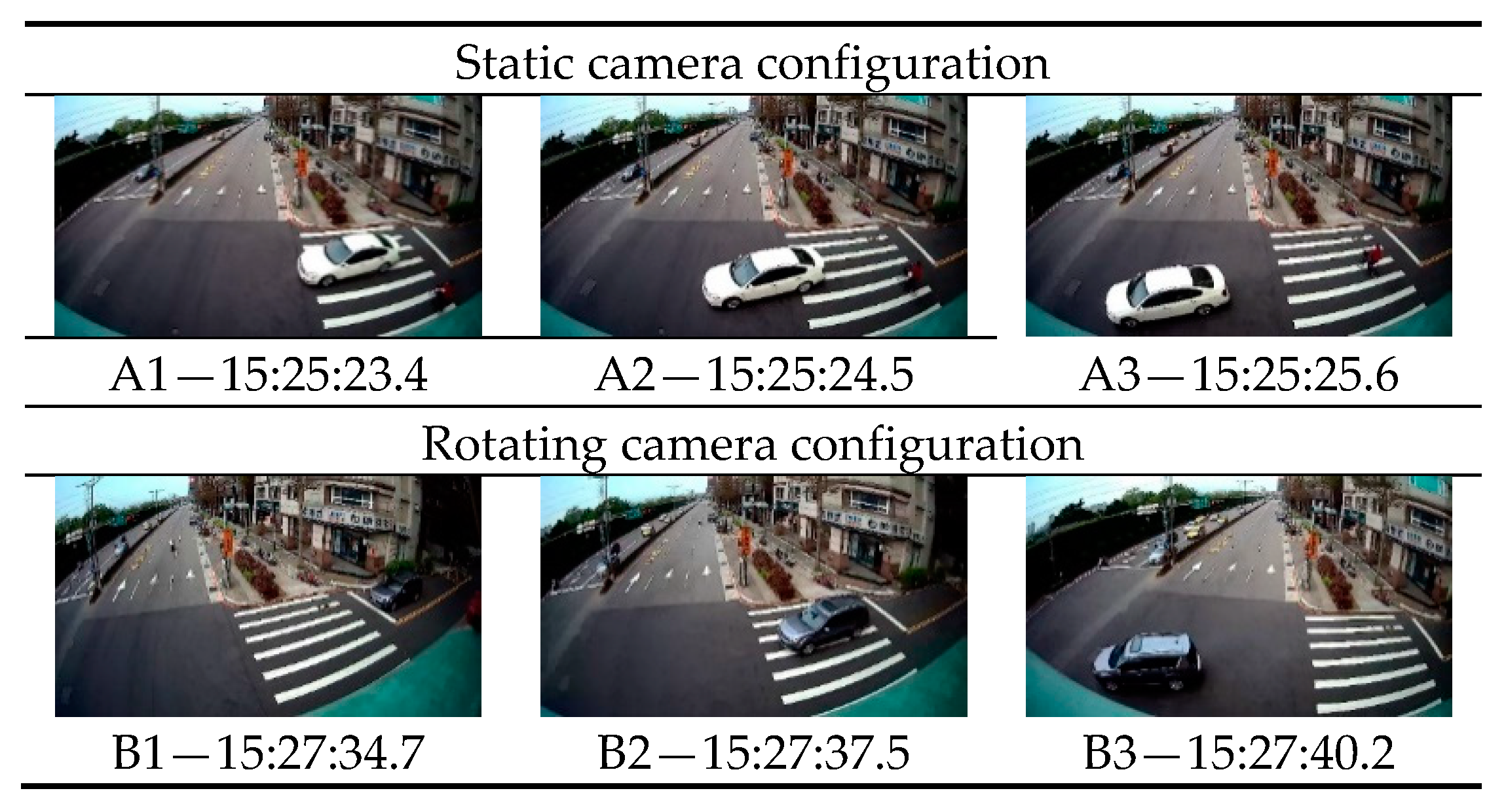
The proposed method is implemented on street-view images acquired using a SAMPO PTZ camera in a stationary and rotating configuration. The focal length of the SAMPO PTZ camera is 2.8 mm and it has an image size of 1080 × 1920 pixels. The field of view is approximately 140 degrees by the capability of rotating 355 and 90 degrees in horizontal and vertical directions, respectively. The first image of the camera is set as the reference coordinate system. The equation of the ground plane is given as , accordingly. The recognition model has been trained on the common objects in context (COCO) dataset [53], which contains over 2.5 million labeled instances in 330,000 images. Figure 9 shows a fraction of the street-view image sequence and their timestamps, in which the PTZ camera is set on a footbridge with a 5.1 m height from the given ground plane. The minimum blob area in motion segmentation is set as 1000 pixels to banish trivial patches. A1 to A3 shows the acquired images when the camera is static, whereas B1 to B3 depicts the acquired images when the camera is rotating.
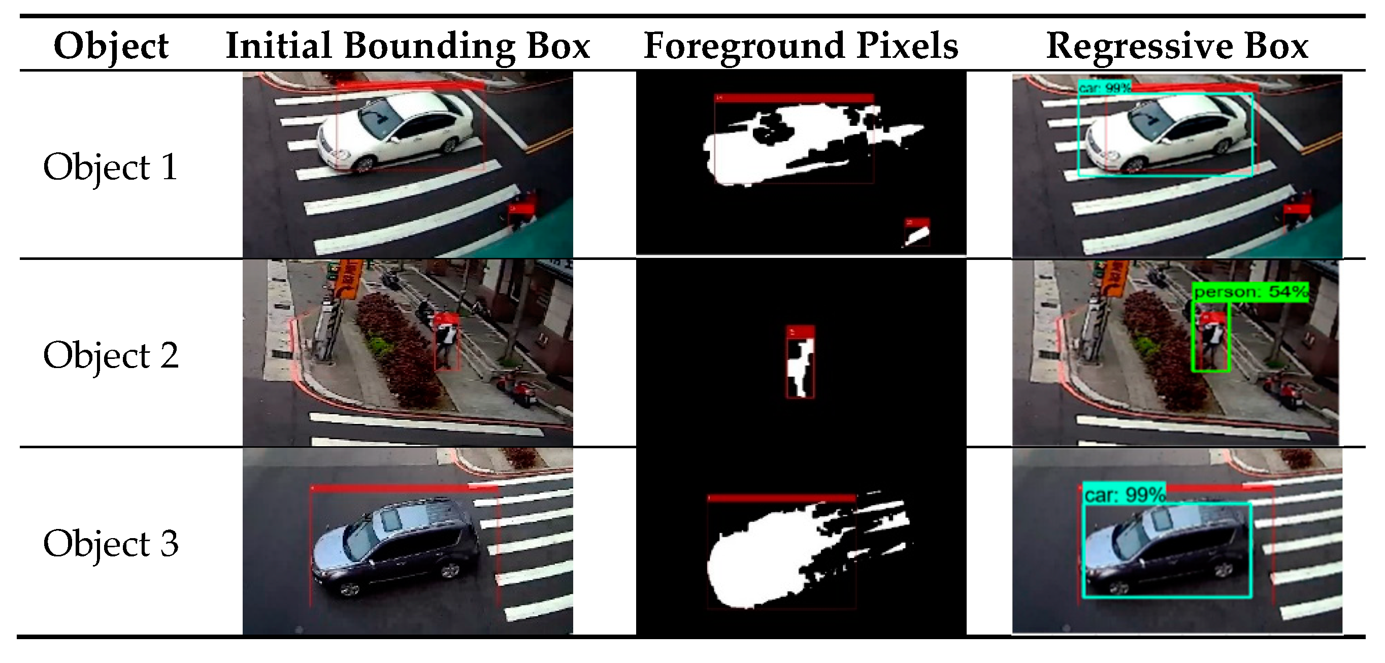
Figure 10 demonstrates the motion segmentation and the recognition results of the sequences. In the light of the red bounding boxes, the resulting foreground pixels of motion segmentation is not reliable and sensitive to the shadow and reflection influence. However, the regressive bounding boxes derived from the recognition process can be used to improve the description of the moving object boundaries. Only the foreground pixels of an object surrounded by the regressive bounding boxes are used to estimate the geometric attributes of the object. In this study, the lowest foreground pixel in the middle of the regressive bounding box is defined as the foot point, and the height of the object is computed accordingly.
Table 2 shows the statistic geometric attributes in terms of the recognized object classes, object heights, and moving velocity. In this case, the keyframes are selected every 10 frames for the computation of the object heights and velocity. This information can further contribute to the identification and prediction of object behavior.
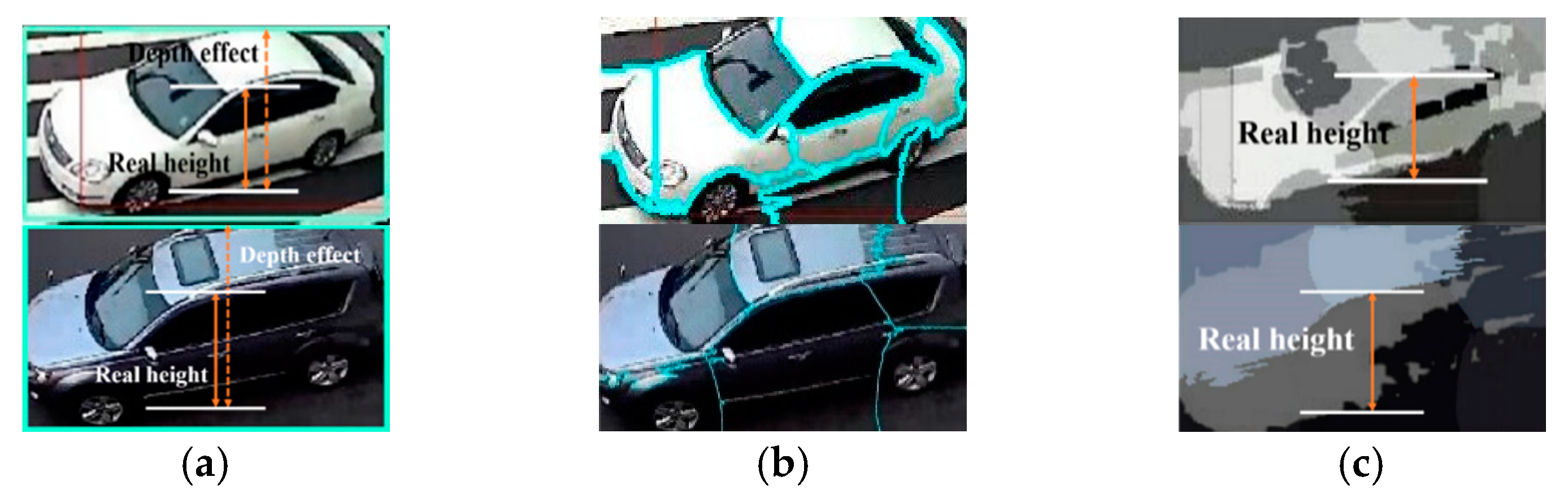
Referring to the general specification of the objects, the geometric estimates of the recognized objects in Table 2 seem promising. The camera motion rectification adjusts the relative motion between the rotating camera and objects. By combining the motion segmentation and the recognition process, the regions of the moving objects in images can be assigned properly, and therefore facilitates the determination of the moving object locations over time. The statistics of velocity also reveal the statuses of Objects 1 and 3 correctly, showing that they were accelerating rapidly when starting the movement at the intersection. The accuracy of the geometric attributes, however, is highly correlated to the quality of the foreground object detection. If the foreground pixels of an object cannot describe the object completely, obvious errors would be induced in estimating the object’s location and height. Currently, the object height is measured based on the height displacement of the object in the image. In cases that a moving object comprises a depth, the height estimate would convey a conspicuous error, which can be seen in the standard deviation of Objects 1 and 3 in Table 2, since vehicles are the main class of moving objects with a depth effect. By contrast, the height estimate of the pedestrian is promising due to the nature of the body shape. As demonstrated in Figure 11, a super-pixel segmentation [54] is performed on the recognized result of a vehicle to derive its subregions. These regions are superimposed onto their foreground pixels to eliminate the depth interference in estimating the object height. Nevertheless, the segmenting process assumes the top of the vehicle should locate at the center segment of the regressive bounding box, and the object height is determined from the foot point to the highest foreground pixel in the center segment along the direction of the ground normal vector.
In light of Table 3, the modified height estimates of the recognized Objects 1 and 3 show promising results and approach the official specification of these two vehicles. In addition, the standard deviation of the estimates is improved up to around 50% as compared with those in Table 2. However, the integrity of the foreground pixels, the heading poses, and image appearances of vehicles still frustrate the effectiveness of the modified height estimation for vehicle classes.
3.3. Performance Evaluation of Various Networks
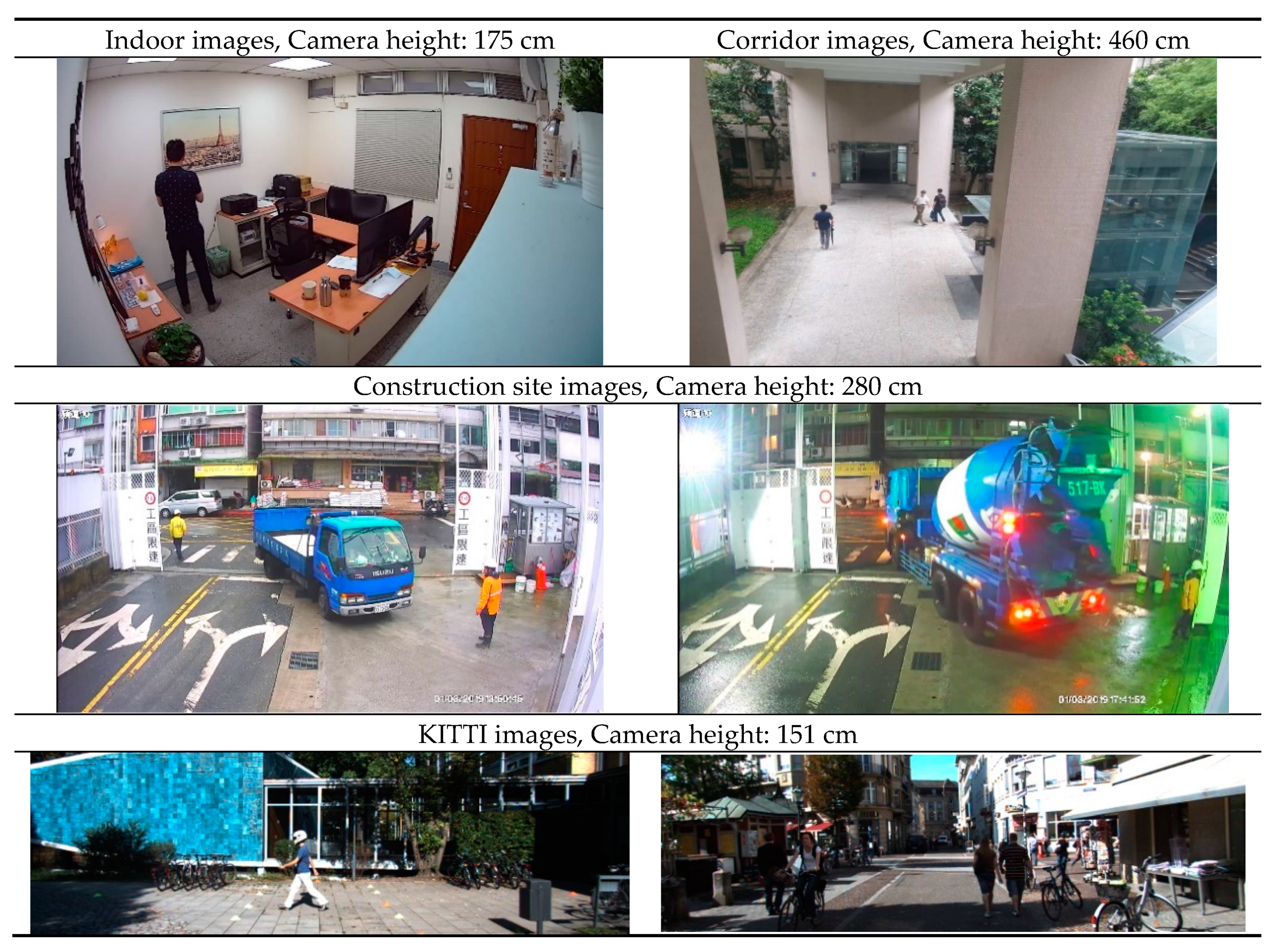
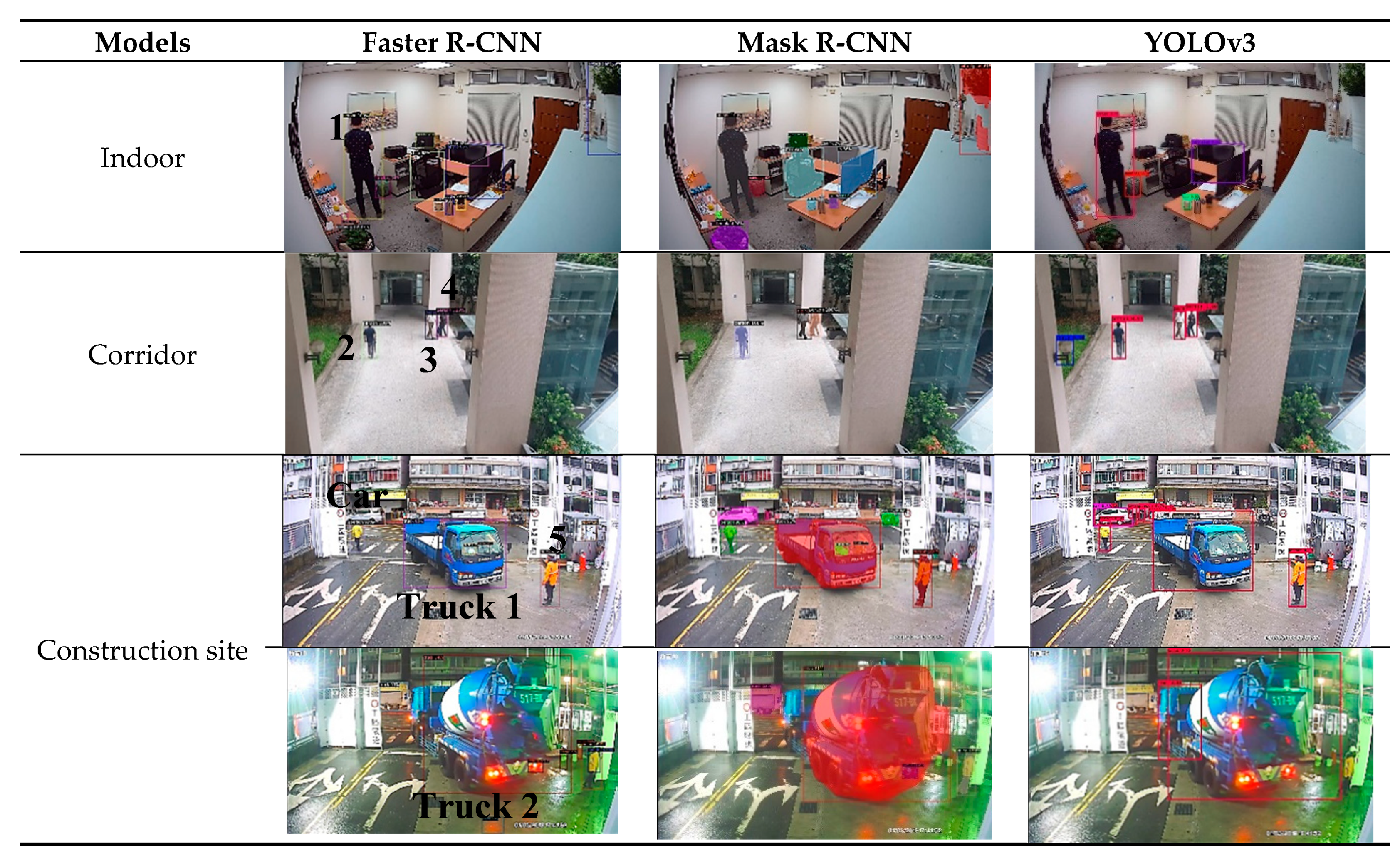
To gain insight into the effectiveness of different model networks, including Faster R-CNN, mask region-based convolutional neural network (Mask R-CNN) [55], and the improvement of you only look once (YOLOv3) [56], this study carried out the comparison of the object detection by adopting PTZ camera images in an indoor environment, a corridor, and a construction site, and further assess the accuracy of the estimated geometric measurement using the KITTI benchmark. Figure 12 shows the image sequences along with the camera height setup used for estimation. For each dataset, the proposed method is integrated with these three model networks to reveal the estimation of detected objects, respectively. These images contain various illumination conditions, different types of objects, and view angles. In this case, the keyframes were selected every three frames from 30 sequential images. It should be noted that the evaluation lies in the accuracy of the geometric measurement instead of focusing on the completeness or correctness of object recognition. Therefore, the labels of person, bicycle, car, and truck are selected in this case, and only if the similarity of a specific label is higher than 70%, then the detected object is introduced for the geometric analysis. The quantitative results reflect the adaptability of these models for the surveillance and geometric measurement tasks. Figure 13 shows the object detection and recognition results of each models, while Table 4 reports the height estimates of the selected objects. On the one hand, in Figure 13, the detection results show the similarity among these three models in most scenes. However, when illumination conditions deteriorate or obstruction occurs, all the similarity scores and completeness of each label decrease, mainly Mask R-CNN, in which the deterioration of object recognition can be found in the image sequences of a construction site. The completeness and correctness of each model also degenerate at nightfall. On the other hand, the estimates in Table 4 agree with the visual results, showing similar heights among these three models, where “object ID” refers to the legends in the first column in Figure 13. The mean and standard deviation are calculated from the estimates of all keyframes. In view of Equations (14)–(17), the height estimate of the person on an indoor image set achieves an error of 3.5 cm by using a keyframe pair based on Faster R-CNN, where the true value of 177 cm lies in the reasonable range of 176.8 ± 3.5 cm.
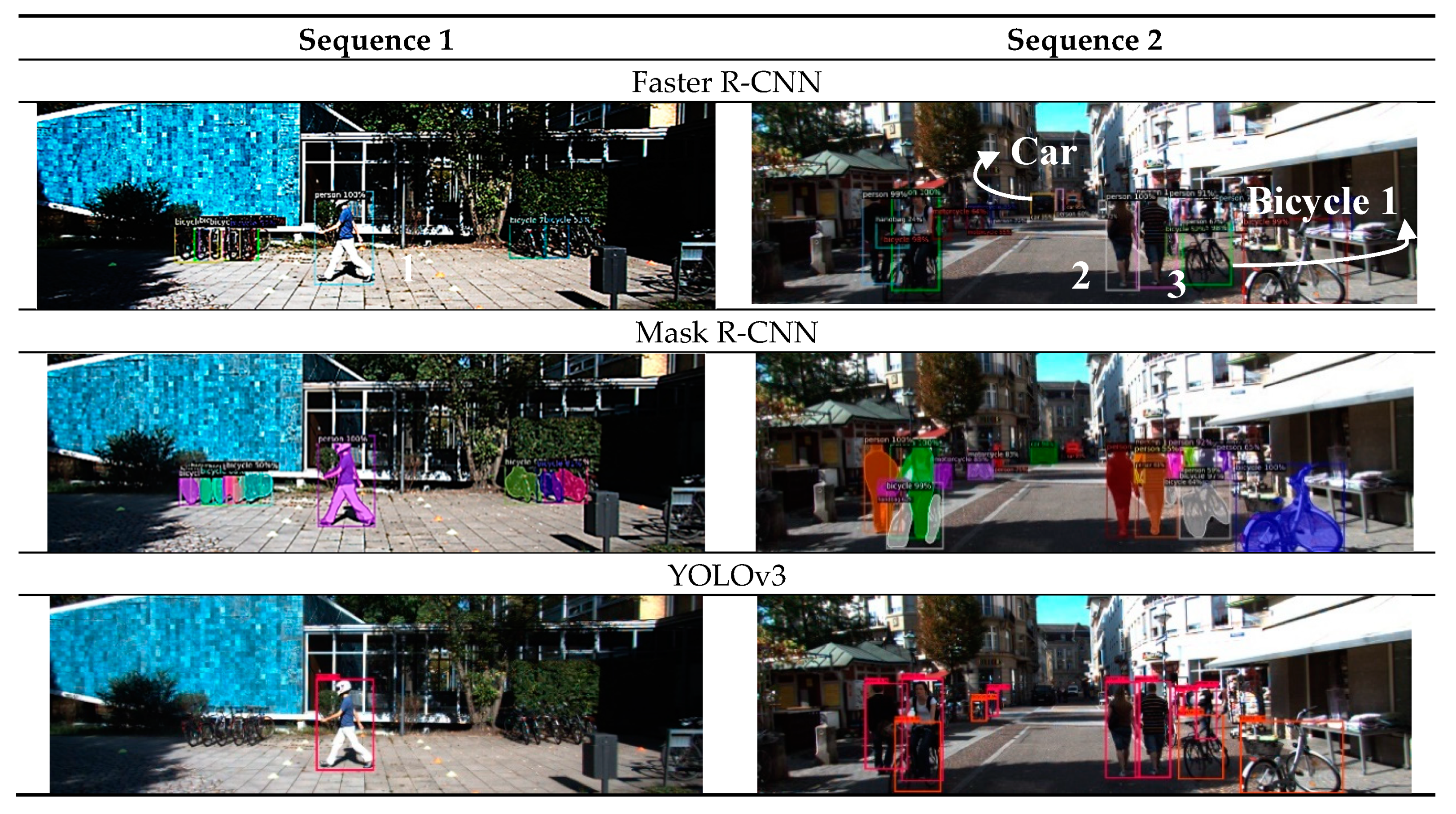
Moreover, this study leverages the image sequences of the KITTI benchmark (last row in Figure 12) to compare the estimated object heights with those provided by KITTI’s specifications. In this case, the labels of person and bicycle were selected for evaluation, where the chosen objects are noted in the first row in Figure 14. It should be noted that YOLOv3 reveals slightly poor instance segmentation and detection results in image Sequence 1 due to its weighting strategy. Table 5 shows the evaluation results. Among Faster R-CNN, Mask-RCNN, and YOLOv3, Faster R-CNN results in relatively low errors and low standard deviations.
Regarding the evaluation of the object height, it is apparent that most of the estimates are higher than the values provided by KITTI. This could have resulted from the inaccurate setting of camera height, mismatching assumption, or the discrepancy in measurement aspects. Nevertheless, all the differences are less than 10 cm, which is acceptable in some practical applications. Additionally, this evaluation shows that YOLOv3 demonstrated low performance in object detection in terms of completeness and correctness, whereas Faster R-CNN demonstrated the best performance in object detection in accuracy and precision. This evaluation also reflects the limitation of the proposed method. The precise height of camera is indispensable for an accurate height estimate. Nevertheless, in most of the cases, a surveillance camera can be set up with a priori known condition, and the reliability of the estimates can be further reviewed by their theoretical accuracy computed by using Equations (14)–(17).
4. Conclusions
This paper contributes a scheme to acquire 3D geometric attributes of moving objects by using Faster R-CNN with a stationary and rotating PTZ camera configuration, which is rarely discussed in the literature. The effectiveness of the proposed method in yielding the moving distances, moving velocity, object heights, and object recognition from a monocular camera has been validated through synthetic and real datasets. Regarding the specific camera configuration in this study, the 3D positions are determined by combining single and multiple view solutions to render accurate estimates. Inevitably, interference such as shadow effects and occlusions would deteriorate the reliability and completeness of the motion segmentation. However, by leveraging the deep learning recognition technique, the regressive bounding boxes resulted from Faster R-CNN facilitate the refinement of the object boundaries, which can directly improve the quality of the geometric estimation. Moreover, a super-pixel segmentation process is specifically applied to the vehicle class to further improve its object height estimation by reducing the depth effect. The proposed approach calculates the height and speed estimates of the recognized moving objects, including pedestrians and vehicles, and shows promising results and application potential through existing CCTVs at a very low cost. A continued investigation on enhancing the computational efficiency and the exploration of object moving behavior should be addressed in future work.
Author Contributions
T.-Y.C. and M.-D.Y. conceive and design the study; T.-Y.C. is the primary author and preparer of the manuscript; M.-D.Y. contributes editing and proof-reading; T.-Y.C. and D.-J.J. conduct the data collecting and analysis; J.-Y.H. provides hardware and software; T.-Y.C. and D.-J.J. conduct image processing and results; M.-D.Y. and J.-Y.H. provide project supervision. All authors have read and agreed to the published version of the manuscript.
Funding
This research is partially supported by the Ministry of Science and Technology under grant number 108-2634-F-005-003 through Pervasive AI Research (PAIR) Labs, Taiwan, and “Innovation and Development Center of Sustainable Agriculture” from The Featured Areas Research Center Program within the framework of the Higher Education Sprout Project by the Ministry of Education (MOE) in Taiwan.
Acknowledgments
This publication would not be possible without constructive suggestions from reviewers, which are much appreciated.
Conflicts of Interest
The authors declare no conflict of interest.
References
- Yazdi, M.; Bouwmans, T. New trends on moving object detection in video images captured by a moving camera: A survey. Comput. Sci. Rev. 2018, 28, 157–177. [Google Scholar] [CrossRef]
- Kandylakis, Z.; Vasili, K.; Karantzalos, K. Fusing multimodal video data for detecting moving objects/targets in challenging indoor and outdoor scenes. Remote Sens. 2019, 11, 446. [Google Scholar] [CrossRef] [Green Version]
- Maglogiannis, I.G. Emerging Artificial Intelligence Applications in Computer Engineering: Real Word AI Systems with Applications in eHealth, HCI, Information Retrieval and Pervasive Technologies; IOS Press: Amsterdam, The Netherlands, 2007. [Google Scholar]
- Zang, Y.P.; Zhang, F.J.; Di, C.A.; Zhu, D.B. Advances of flexible pressure sensors toward artificial intelligence and health care applications. Mater. Horiz. 2015, 2, 140–156. [Google Scholar] [CrossRef]
- Zhang, L.Q.; Zhang, L. Deep learning-based classification and reconstruction of residential scenes from large-scale point clouds. IEEE Trans. Geosci. Remote Sens. 2018, 56, 1887–1897. [Google Scholar] [CrossRef]
- Yang, M.D.; Su, T.C. Automated diagnosis of sewer pipe defects based on machine learning approaches. Expert Syst. Appl. 2008, 35, 1327–1337. [Google Scholar] [CrossRef]
- Su, T.C.; Yang, M.D. Application of morphological segmentation to leaking defect detection in sewer pipelines. Sensors 2014, 14, 8686–8704. [Google Scholar] [CrossRef] [PubMed] [Green Version]
- Zhong, Z.L.; Li, J.; Luo, Z.M.; Chapman, M. Spectral–spatial residual network for hyperspectral image classification: A 3-D deep learning framework. IEEE Trans. Geosci. Remote Sens. 2018, 56, 847–858. [Google Scholar] [CrossRef]
- Yang, M.D.; Su, T.C.; Lin, H.Y. Fusion of infrared thermal image and visible image for 3D thermal model reconstruction using smartphone. Sensors 2018, 18, 2003. [Google Scholar] [CrossRef] [Green Version]
- Ojha, S.; Sakhare, S. Image processing techniques for object tracking in video surveillance—A survey. In Proceedings of the 2015 International Conference on Pervasive Computing, Pune, India, 8–10 January 2015. [Google Scholar]
- Zhang, G.; Jia, J.; Xiong, W.; Wong, T.T.; Heng, P.A.; Bao, H. Moving object extraction with a hand-held camera. In Proceedings of the 2007 International Conference on Computer Vision, Rio de Janeiro, Brazil, 14–21 October 2007. [Google Scholar]
- Das, D.; Saharia, S. Implementation and performance evaluation of background subtraction algorithms. Int. J. Comput. Sci. Appl. 2014, 4, 50–55. [Google Scholar] [CrossRef] [Green Version]
- Nguyen, V.T.; Vu, H.; Tran, T.H. An efficient combination of RGB and depth for background subtraction. In The National Foundation for Science and Technology Development (NAFOSTED) Conference on Information and Computer Science; Dang, Q.A., Nguyen, X.H., Le, H.B., Nguyen, V.H., Bao, V.N.Q., Eds.; Springer: Cham, Switzerland, 2014; pp. 49–63. [Google Scholar]
- Yin, P.; Criminisi, A.; Winn, J.; Essa, I. Bilayer segmentation of webcam videos using tree-based classifiers. IEEE Trans. Pattern Anal. Mach. Intell. 2011, 33, 30–42. [Google Scholar] [CrossRef] [Green Version]
- Criminisi, A.; Cross, G.; Blake, A.; Kolmogorov, V. Bilayer segmentation of live video. In Proceedings of the 2006 IEEE Computer Society Conference on Computer Vision and Pattern Recognition, New York, NY, USA, 17–22 June 2006; pp. 53–60. [Google Scholar]
- Sun, J.; Zhang, W.; Tang, X.; Shum, H.Y. Background cut. In Proceedings of the 2006 European Conference on Computer Vision, Graz, Austria, 7–13 May 2006; pp. 628–641. [Google Scholar]
- Athanesious, J.J.; Suresh, P. Systematic survey on object tracking methods in video. J. Adv. Comput. Eng. Technol. 2012, 1, 242–247. [Google Scholar]
- Balaji, S.R.; Karthikeyan, S. A survey on moving object tracking using image processing. In Proceedings of the 2017 International Conference on Intelligent Systems and Control, Coimbatore, India, 5–6 January 2017. [Google Scholar]
- Yang, M.D.; Huang, K.S.; Kuo, Y.H.; Tsai, H.P.; Lin, L.M. Spatial and spectral hybrid image classification for rice-lodging assessment through UAV imagery. Remote Sens. 2017, 9, 583. [Google Scholar] [CrossRef] [Green Version]
- Kadim, Z.; Daud, M.M.; Radzi, S.S.M.; Samudin, N.; Woon, H.H. Method to detect and track moving object in non-static PTZ camera. In Proceedings of the International MultiConference of Engineers and Computer Scientists, Hong Kong, China, 13–15 March 2013. [Google Scholar]
- Yang, M.D.; Su, T.C.; Pan, N.F.; Liu, P. Feature extraction of sewer pipe defects using wavelet transform and co-occurrence matrix. Int. J. Wavelets Multiresolut. Inf. Process. 2011, 9, 211–225. [Google Scholar] [CrossRef]
- Nayagam, M.G.; Ramar, D.K. A survey on real time object detection and tracking algorithms. Int. J. Appl. Eng. Res. 2015, 10, 8290–8297. [Google Scholar]
- Chauhan, A.K.; Krishan, P. Moving object tracking using gaussian mixture model and optical flow. Int. J. Adv. Res. Comput. Sci. Softw. Eng. 2013, 3, 243–246. [Google Scholar]
- Cheung, S.S.; Kamath, C. Robust techniques for background subtraction in urban traffic video. In Proceedings of the 2004 Visual Communications and Image Processing, San Jose, CA, USA, 18–22 January 2004; Volume 5308, pp. 881–892. [Google Scholar]
- Sankari, M.; Meena, C. Estimation of dynamic background and object detection in noisy visual surveillance. Int. J. Adv. Comput. Sci. Appl. 2011, 2, 77–83. [Google Scholar] [CrossRef] [Green Version]
- Brutzer, S.; Höferlin, B.; Heidemann, G. Evaluation of background subtraction techniques for video surveillance. In Proceedings of the 2011 IEEE Conference on Computer Vision and Pattern Recognition, Providence, RI, USA, 20–25 June 2011. [Google Scholar]
- Rakibe, R.S.; Patil, B.D. Background subtraction algorithm based human motion detection. Int. J. Sci. Res. Publ. 2013, 3, 2250–3153. [Google Scholar]
- Vedula, S.; Baker, S.; Rander, P.; Collins, R.; Kanade, T. Three-dimensional scene flow. In Proceedings of the 1999 International Conference on Computer Vision, Kerkyra, Greece, 20–27 September 1999; Volume 2, pp. 722–729. [Google Scholar]
- Yang, M.D.; Chao, C.F.; Lu, L.Y.; Huang, K.S.; Chen, Y.P. Image-based 3D scene reconstruction and exploration in augmented reality. Autom. Constr. 2013, 3, 48–60. [Google Scholar] [CrossRef]
- Lalonde, M.; Foucher, S.; Gagnon, L.; Pronovost, E.; Derenne, M.; Janelle, A. A system to automatically track humans and vehicles with a PTZ camera. In Proceedings of the SPIE Defense and Security: Visual Information Processing XVI (SPIE #6575), Orlando, FL, USA, 30 April 2007. [Google Scholar]
- Black, M.J.; Anandan, P. The robust estimation of multiple motions: Parametric and piecewise-smooth flow fields. Comput. Vis. Image Underst. 1996, 63, 75–104. [Google Scholar] [CrossRef]
- Yang, M.D.; Su, T.C.; Pan, N.F.; Yang, Y.F. Systematic image quality assessment for sewer inspection. Expert Syst. Appl. 2011, 38, 1766–1776. [Google Scholar] [CrossRef]
- Parekh, H.S.; Thakore, D.G.; Jaliya, U.K. A survey on object detection and tracking methods. Int. J. Innov. Res. Comput. Commun. Eng. 2014, 2, 2970–2978. [Google Scholar]
- Long, Y.; Gong, Y.; Xiao, Z.; Liu, Q. Accurate object localization in remote sensing images based on convolutional neural networks. IEEE Trans. Geosci. Remote Sens. 2017, 55, 2486–2498. [Google Scholar] [CrossRef]
- Nimmagadda, Y.; Kumar, K.; Lu, Y.H.; Lee, G.C.S. Real-time moving object recognition and tracking using computation offloading. In Proceedings of the 2010 Intelligent Robots and Systems, Taipei, Taiwan, 18–22 October 2010; pp. 2449–2455. [Google Scholar]
- Hu, W.C.; Chen, C.H.; Chen, T.Y.; Huang, D.Y.; Wu, Z.C. Moving object detection and tracking from video captured by moving camera. J. Vis. Commun. Image Represent. 2015, 30, 164–180. [Google Scholar] [CrossRef]
- Ren, S.; He, K.; Girshick, R.; Sun, J. Faster R-CNN: Towards real-time object detection with region proposal networks. In Proceedings of the Advances in Neural Information Processing Systems, Montreal, QC, Canada, 7–12 December 2015; pp. 91–99. [Google Scholar]
- Girshick, R.; Donahue, J.; Darrell, T.; Malik, J. Region-based convolutional networks for accurate object detection and segmentation. IEEE Trans. Pattern Anal. Mach. Intell. 2016, 38, 142–158. [Google Scholar] [CrossRef]
- Girshick, R. Fast R-CNN. In Proceedings of the IEEE International Conference on Computer Vision, Santiago, Chile, 7–13 December 2015; pp. 1440–1448. [Google Scholar]
- Jiao, J.; Zhang, Y.; Sun, H. A densely connected end-to-end neural network for multiscale and multiscene SAR ship detection. IEEE Access. 2018, 6, 20881–20892. [Google Scholar] [CrossRef]
- Akcay, S.; Kundegorski, M.E.; Willcocks, C.G.; Breckon, T.P. Using deep convolutional neural network architectures for object classification and detection within X-ray baggage security imagery. IEEE Trans. Inf. Forensic Secur. 2018, 13, 2203–2215. [Google Scholar] [CrossRef] [Green Version]
- Yang, M.D.; Tseng, H.H.; Hsu, Y.C.; Tsai, H.P. Semantic Segmentation Using Deep Learning with Vegetation Indices for Rice Lodging Identification in Multi-date UAV Visible Images. Remote Sens. 2020, 12, 633. [Google Scholar] [CrossRef] [Green Version]
- Ferone, A.; Maddalena, L. Neural background subtraction for pan-tilt-zoom cameras. IEEE Trans. Syst. Man Cybern. Syst. 2013, 44, 571–579. [Google Scholar] [CrossRef]
- Wu, J. Complexity and accuracy analysis of common artificial neural networks on pedestrian detection. MATEC Web Conf. 2018, 232, 01003. [Google Scholar] [CrossRef]
- Geiger, A.; Lenz, P.; Urtasun, R. Are we ready for autonomous driving? In The KITTI vision benchmark suite. In Proceedings of the IEEE Conference on Computer Vision and Pattern Recognition, Providence, RI, USA, 18–20 June 2012; pp. 3354–3361. [Google Scholar]
- Bay, H.; Ess, A.; Tuytelaars, T.; Gool, L.V. SURF: Speeded up robust features. Comput. Vis. Image Underst. 2008, 110, 346–359. [Google Scholar] [CrossRef]
- Raguram, R.; Chum, O.; Pollefeys, M.; Matas, J.; Frahm, J. USAC: A universal framework for random sample consensus. IEEE Trans. Pattern Anal. Mach. Intell. 2013, 35, 2022–2038. [Google Scholar] [CrossRef] [PubMed]
- Longuet-Higgins, H.C. A computer algorithm for reconstructing a scene from two projections. Nature 1981, 293, 133–135. [Google Scholar] [CrossRef]
- Yang, M.D.; Huang, K.S.; Yang, Y.F.; Lu, L.Y.; Feng, Z.Y.; Tsai, H.P. Hyperspectral image classification using fast and adaptive bidimensional empirical mode decomposition with minimum noise fraction. IEEE Geosci. Remote Sens. Lett. 2016, 13, 1950–1954. [Google Scholar] [CrossRef]
- Zoph, B.; Le, Q.V. Neural architecture search with reinforcement learning. In Proceedings of the 2017 International Conference on Learning Representations, Toulon, France, 24–26 April 2017. [Google Scholar]
- Engel, J.; Schöps, T.; Cremers, D. LSD-SLAM: Large-scale direct monocular SLAM. In Proceedings of the 2014 European Conference on Computer Vision—ECCV, Zurich, Switzerland, 6–12 September 2014; pp. 834–849. [Google Scholar]
- Mur-Artal, R.; Montiel, J.M.M.; Tardós, J.D. ORB-SLAM: A versatile and accurate monocular SLAM system. IEEE Trans. Robot. 2015, 31, 1147–1163. [Google Scholar] [CrossRef] [Green Version]
- Lin, T.Y.; Maire, M.; Belongie, S.; Hays, J.; Perona, P.; Ramanan, D.; Dollár, P.; Zitnick, C.L. Microsoft COCO: Common objects in context. In Proceedings of the 2014 European Conference on Computer Vision (ECCV), Zurich, Switzerland, 6–12 September 2014; pp. 740–755. [Google Scholar]
- Achanta, R.; Shaji, A.; Smith, K.; Lucchi, A.; Fua, P.; Susstrunk, S. SLIC superpixels compared to state-of-the-art superpixel methods. IEEE Trans. Pattern Anal. Mach. Intell. 2012, 34, 2274–2282. [Google Scholar] [CrossRef] [PubMed] [Green Version]
- He, K.; Gkioxari, G.; Dollar, P.; Girshick, R. Mask R-CNN. In Proceedings of the IEEE International Conference on Computer Vision (ICCV), Venice, Italy, 22–29 October 2017; pp. 2961–2969. [Google Scholar]
- Redmon, J.; Farhadi, A. YOLOv3: An incremental improvement. arXiv 2018, arXiv:1804.02767. [Google Scholar]
Figure 1.
Block diagram of the proposed scheme.

Figure 2.
The camera motion rectification between t and t + 1 frames.

Figure 3.
The illustration of the faster region-based convolutional neural network (Faster R-CNN) unified network.
Figure 3.
The illustration of the faster region-based convolutional neural network (Faster R-CNN) unified network.

Figure 4.
The foreground object pixels polished by the regressive bounding box.

Figure 5.
The illustration of the configuration between a camera and an object, where H is a prior known camera height in object coordinate system; N is the normal vector of the ground plane; T and B are the unknowns that indicate the top and bottom points used for calculating the object height h.
Figure 5.
The illustration of the configuration between a camera and an object, where H is a prior known camera height in object coordinate system; N is the normal vector of the ground plane; T and B are the unknowns that indicate the top and bottom points used for calculating the object height h.

Figure 6.
A fraction of the image sequence.


Figure 7.
The results of the motion segmentation.

Figure 8.
The detected foreground objects.

Figure 9.
A fraction of the street-view image sequence.

Figure 10.
The motion segmentation and the recognition results.

Figure 11.
Segmentation of the vehicle class. (a) Object depth effect; (b) Super-pixel segments; (c) Superimposition.
Figure 11.
Segmentation of the vehicle class. (a) Object depth effect; (b) Super-pixel segments; (c) Superimposition.

Figure 12.
Image dataset for performance evaluation.

Figure 13.
Results of object detection using various models in different scenarios.

Figure 14.
Results of object detection applying various models to KITTI dataset.


Table 1.
The quantitative indices of the foreground detection.
| Static Camera Configuration | ||||||||
|---|---|---|---|---|---|---|---|---|
| Quality Indexes | Stable Lighting | Lighting Change | ||||||
| a–b | b–c | c–d | Avg. | a–b | b–c | c–d | Avg. | |
| Recall | 0.78 | 0.96 | 0.75 | 0.83 | 0.65 | 0.88 | 0.79 | 0.77 |
| Precision | 0.90 | 0.95 | 0.99 | 0.94 | 0.95 | 0.92 | 0.93 | 0.94 |
| 0.83 | 0.95 | 0.85 | 0.88 | 0.77 | 0.77 | 0.85 | 0.80 | |
| Rotating Camera Configuration | ||||||||
| Stable lighting | Lighting change | |||||||
| a–b | b–c | c–d | Avg. | a–b | b–c | c–d | Avg. | |
| Recall | 0.69 | 0.86 | 0.82 | 0.79 | 0.70 | 0.92 | 0.59 | 0.74 |
| Precision | 0.97 | 0.99 | 0.99 | 0.98 | 0.98 | 0.99 | 0.99 | 0.98 |
| 0.81 | 0.92 | 0.89 | 0.87 | 0.82 | 0.83 | 0.74 | 0.80 | |
Table 2.
The observed geometric attributes.
| Class | Height (cm) | Velocity (km/hr) | |||
|---|---|---|---|---|---|
| Mean | Std. dev. | Mean | Std. dev. | ||
| Object 1 | White vehicle | 170.8 | 6.4 | 21.3 | 7.3 |
| Object 2 | Pedestrian | 168 | 3.3 | 4.7 | 1.5 |
| Object 3 | Blue vehicle | 180.2 | 4.3 | 27.6 | 9.9 |
Table 3.
Modified object height estimates.
| Class | Height (cm) | Height (cm) | ||
|---|---|---|---|---|
| Mean | Std. dev. | Specification | ||
| Object 1 | White vehicle | 161.4 | 3.1 | 148 |
| Object 3 | Blue vehicle | 174.4 | 2.6 | 171 |
Table 4.
Results of geometric measurement using various models in different scenarios.
| Object ID | Faster R-CNN | Mask R-CNN | YOLOv3 | ||||
|---|---|---|---|---|---|---|---|
| Height (cm) | |||||||
| Mean | Std. dev. | Mean | Std. dev. | Mean | Std. dev. | ||
| Indoor | Person 1 | 176.8 | 2.3 | 177.3 | 1.9 | 175.6 | 2.1 |
| Corridor | Person 2 | 177.5 | 3.1 | 176.1 | 2.3 | 1.77.9 | 3.2 |
| Person 3 | 176.5 | 2.6 | 174.6 | 3.2 | 176.6 | 2.9 | |
| Person 4 | 173.2 | 2.5 | 169.8 | 4.8 | 174.2 | 2.3 | |
| Construction site | Person 5 | 179.7 | 1.8 | 177.2 | 4.4 | 179.2 | 2.2 |
| Car | 169.7 | 2.5 | 172.6 | 2.4 | 171.6 | 2.5 | |
| Truck 1 | 193.6 | 2.7 | 194.7 | 3.2 | 203.5 | 3.3 | |
| Truck 2 | 324.7 | 2.7 | 304.3 | 3.5 | 3.28 | 2.9 | |
Table 5.
Evaluation of geometric measurement applying various models to KITTI dataset.
| Object ID | Faster R-CNN | Mask R-CNN | YOLOv3 | KITTI | ||||
|---|---|---|---|---|---|---|---|---|
| Height (cm) | ||||||||
| Mean | Std. dev. | Mean | Std. dev. | Mean | Std. dev. | True Value | ||
| Sequence 1 | Person 1 | 185.6 | 1.7 | 184.3 | 1.4 | 186.2 | 1.6 | 182 |
| Sequence 2 | Person 2 | 174.1 | 2.5 | 174.6 | 3.4 | 179.5 | 2.8 | 173 |
| Person 3 | 181.5 | 2.1 | 182.2 | 3.1 | 186.7 | 2.5 | 179 | |
| Car | 206.6 | 1.7 | 204.4 | 2.2 | n/a | 211 | ||
| Bicycle 2 | 107.6 | 3.5 | 114.3 | 2.3 | 116.2 | 3.8 | 110 | |
© 2020 by the authors. Licensee MDPI, Basel, Switzerland. This article is an open access article distributed under the terms and conditions of the Creative Commons Attribution (CC BY) license (http://creativecommons.org/licenses/by/4.0/).
Share and Cite
MDPI and ACS Style
Chuang, T.-Y.; Han, J.-Y.; Jhan, D.-J.; Yang, M.-D. Geometric Recognition of Moving Objects in Monocular Rotating Imagery Using Faster R-CNN. Remote Sens. 2020, 12, 1908. https://0-doi-org.brum.beds.ac.uk/10.3390/rs12121908
AMA Style
Chuang T-Y, Han J-Y, Jhan D-J, Yang M-D. Geometric Recognition of Moving Objects in Monocular Rotating Imagery Using Faster R-CNN. Remote Sensing. 2020; 12(12):1908. https://0-doi-org.brum.beds.ac.uk/10.3390/rs12121908
Chicago/Turabian StyleChuang, Tzu-Yi, Jen-Yu Han, Deng-Jie Jhan, and Ming-Der Yang. 2020. "Geometric Recognition of Moving Objects in Monocular Rotating Imagery Using Faster R-CNN" Remote Sensing 12, no. 12: 1908. https://0-doi-org.brum.beds.ac.uk/10.3390/rs12121908
Note that from the first issue of 2016, this journal uses article numbers instead of page numbers. See further details here.