MODIS and VIIRS Calibration History and Future Outlook

Sciences and Exploration Directorate, NASA Goddard Space Flight Center, Greenbelt, MD 20771, USA
*
Author to whom correspondence should be addressed.
Remote Sens. 2020, 12(16), 2523; https://0-doi-org.brum.beds.ac.uk/10.3390/rs12162523
Submission received: 11 July 2020
/
Revised: 3 August 2020
/
Accepted: 3 August 2020
/
Published: 6 August 2020
(This article belongs to the Special Issue The Needs and Path Toward an SI-Traceable Space-based Climate Observing System)
Abstract
:The MODIS is a key instrument for NASA’s EOS program, currently operated onboard the Terra and Aqua spacecraft launched in 1999 and 2002, respectively. The VIIRS is a MODIS follow-on instrument for the JPSS program. Adding to the ones operated onboard the S-NPP and NOAA-20 satellites launched in 2011 and 2017, respectively, three nearly identical VIIRS instruments will also be launched. This will enable the data records from MODIS and VIIRS to be extended beyond 2040. In addition to various applications and scientific studies of the Earth’s system, long-term data records from MODIS and VIIRS observations will greatly benefit the space-based climate observing system. This is attributed to the high-quality measurements and extensive calibration efforts, from pre-launch to post-launch. This paper provides an overview of MODIS and VIIRS calibration history and approaches applied to establish and maintain sensor calibration traceability and accuracy. It illustrates calibration and performance issues through different phases of the mission using examples derived from ground testing equipment, on-board calibrators, and other calibration targets. Moreover, discussed in this paper are outstanding challenges and future efforts to maintain and improve sensor calibration stability and long-term data quality, and to better support the space-based climate observing system.
1. Introduction
The Moderate Resolution Imaging Spectroradiometer (MODIS) is a key instrument for NASA’s Earth Observing System (EOS) Terra (formerly the EOS AM-1) and Aqua (formerly the EOS PM-1) missions [1,2]. Since its launch in December 1999, the Terra MODIS has successfully operated for more than two decades. Launched in May 2002, the Aqua MODIS has also operated continuously for more than 18 years. The MODIS was developed to support NASA’s EOS program in order to meet the needs of both the operational and scientific community by extending and enhancing the data records established from several legacy Earth-observing sensors, such as the NOAA’s Advanced Very High Resolution Radiometer (AVHRR), the Landsat Thematic Mapper (TM), the Nimbus 7 Coastal Zone Color Scanner (CZCS), the Sea-Viewing Wide Field-of-View Sensor (SeaWiFS), and the NOAA’s High Resolution Infrared Radiation Sounder (HIRS). It was designed to make measurements in 36 spectral bands, covering wavelengths from visible (VIS) to long-wave infrared (LWIR) and spatial resolutions of 250 m, 500 m, and 1 km, and, most importantly, with improved calibration requirements and on-orbit calibration capability over its heritage sensors.
There are more than 30 science products that are routinely generated from MODIS observations and openly distributed to users worldwide [3,4]. Operated in complementary morning and afternoon orbits, with Terra at 10:30 am equatorial crossing time descending southwards and Aqua at 1:30 pm equatorial crossing time ascending northwards, MODIS observations and its data products have supported a wide range of applications and studies of the Earth’s system including key geophysical and environmental parameters of its land, oceans, and atmosphere, and impacts due to natural and human induced effects on the Earth’s climate and its change over time [5,6,7,8]. Table 1 is a summary of key design requirements of MODIS spectral bands and their primary applications, ranging from land cover, surface and cloud temperatures, ocean color, cloud, and aerosols properties.
The Visible Infrared Imaging Radiometer Suite (VIIRS) was originally developed for the National Polar-Orbiting Environmental Satellite System (NPOESS) program, intended to merge and enhance the capabilities of old generation operational weather satellites, such as the NOAA’s Polar-orbiting Operational Environmental Satellite (POES) and the US Department of Defense (DoD)’s Defense Meteorological Satellite Program (DMSP) [9]. As an effort to mitigate the impact due to cost overrun and schedule delay, the NPOESS program was later phased out and transitioned to the Joint Polar Satellite System (JPSS) program operated by NOAA, with NASA being responsible for procuring all flight instruments. Currently, there are two VIIRS instruments operating in space, one onboard the S-NPP satellite launched in October 2011 and another on the NOAA-20 satellite (formerly known as the JPSS-1) launched in November 2017. Designed and built by the same instrument vendor, the VIIRS is a MODIS follow-on instrument with similar spectral range, spatial resolutions, and calibration capability. More than 20 Environmental Data Records (EDRs), mostly inherited from key MODIS science products, are generated from VIIRS observations that support a wide range of applications [10,11,12].
What makes MODIS and VIIRS data sets extremely valuable rests on the fact that their observations are made concurrently with different types of Earth-observing sensors operating on the same platforms and that both sensors are well calibrated and characterized. In addition to MODIS, the Terra spacecraft carries the Advanced Spaceborne Thermal Emission and Reflection Radiometer (ASTER), the Clouds and the Earth’s Radiant Energy System (CERES), the Multi-angle Imaging SpectroRadiometer (MISR), and the Measurements of Pollution in the Troposphere (MOPITT); and the Aqua spacecraft carries the Atmospheric Infrared Sounder (AIRS), the Advanced Microwave Scanning Radiometer for EOS (AMSR-E), the Advanced Microwave Sounding Unit (AMSU), CERES, and the Humidity Sounder for Brazil (HSB). The VIIRS observations from both S-NPP and NOAA-20 satellites are also made together with other sensors, such as the Cross-track Infrared Sounder (CrIS), the Advanced Technology Microwave Sounder (ATMS), CERES, and the Ozone Mapping and Profiler Suite (OMPS). On top of extensive pre-launch calibration and characterization, a set of on-board calibrators (OBC) and regularly scheduled lunar observations are used for MODIS and VIIRS on-orbit calibration. In order to assure that high-quality data products are generated over the entire mission, calibration parameters or look-up tables (LUTs) to the level 1B (L1B) algorithms are updated on an as-needed basis to account for on-orbit changes in sensor responses or performance. Apart from numerous research and science applications, well-calibrated MODIS and VIIRS observations have also played a critical role in support of the space-based climate observing system.
In the following, we provide a brief description of the MODIS and VIIRS instruments in Section 2, including their spectral bands and on-orbit calibration capability. The pre-launch and on-orbit calibration and characterization activities are presented in Section 3 and Section 4, respectively, with a focus on calibration approaches and strategies developed and applied to evaluate sensor performance and to establish sensor calibration traceability and accuracy. Examples derived from ground test equipment, sensor on-board calibrators, lunar observations, and select ground targets are illustrated and discussed. Section 5 highlights outstanding challenges and lessons learned through different phases of the sensor operation and calibration, and future efforts to be made to further improve and maintain MODIS and VIIRS calibration and data quality. Section 6 provides a summary of this paper.
2. MODIS and VIIRS Instruments
The MODIS observations are made in 36 spectral bands that include 20 reflective solar bands (RSB), covering wavelengths from 0.41 to 2.2 µm, and 16 thermal emissive bands (TEB), covering wavelengths from 3.5 to 14.5 µm. To extend the existing data records, several MODIS spectral bands are of the same wavelengths or closely matched with those used in heritage earth-observing sensors. The bandwidths of MODIS spectral bands and their signal-to-noise ratio (SNR) or noise equivalent temperature difference (NEdT) requirements at specified typical radiances are listed in Table 1, along with their primary applications. MODIS bands are located on four focal plane assemblies (FPA) according to their wavelengths: VIS, near-infrared (NIR), short- and mid-wave infrared (SWIR/MWIR or SMIR), and LWIR. The VIS and NIR FPAs are operated without active temperature control, whereas the SMIR and LWIR FPAs are nominally controlled at 83 K, thus referred to as the cold FPAs. MODIS bands 1-2 collect data at 250 m spatial resolution (nadir), bands 3-7 at 500 m, and remaining bands 8-36 at 1 km.
The VIIRS makes measurements in 22 spectral bands, covering wavelengths from 0.41 to 12.0 µm. Sixteen of them are moderate (M) resolution bands that have a nadir spatial resolution of 750 m and five are imaging (I) bands at a 375 m nadir spatial resolution. VIIRS has a unique day/night band (DNB) in the reflective solar region (0.5-0.9 µm) that is operated at three different gains stages, enabling an extremely large dynamic range and allowing data to be collected during both day and nighttime orbits. Listed side-by-side in Table 2 are the bandwidths and spatial resolutions of the VIIRS spectral bands and their corresponding MODIS bands. The VIIRS RSB include bands M1-11 and I1-3 and TEB include bands M12-16 and I4-5. The VIIRS spectral bands are located on three FPAs: VIS/NIR, S/MWIR, and LWIR. During nominal operations, the S/MWIR and LWIR FPAs are controlled at 80 K.
The MODIS design uses separate bands with fixed gains (or dynamic ranges) for measuring low and high radiance scenes (e.g., ocean and land), while the VIIRS design includes several bands (M1-5, M7, and M13) that can collect data at both low or high gain, thus referred to as the dual-gain bands. The use of dual-gain bands can reduce the total number of bands or detectors, and thus the size of the FPA. This could also reduce the sensor design cost. Both MODIS and VIIRS are whisk-broom scanning radiometers with MODIS using a two-sided scan mirror (SM) followed by a fixed telescope and aft optical system and VIIRS using a rotating telescope assembly (RTA) coupled with a two-sided half-angle mirror (HAM) that rotates at half of the RTA speed. The RTA design was adopted for VIIRS in order to minimize the stray light impact on the DNB performance as its dynamic range extends seven orders of magnitude. The RTA design coupled with a HAM located deep inside the system can also reduce the impact due to front optics degradation on the sensor’s RVS and polarization sensitivity. Since on-orbit calibration is typically performed at a fixed scan angle or angle of incidence (AOI) to the SM or HAM, the sensor’s response versus scan angle (RVS) needs to be accurately determined pre-launch for each spectral band/detector and for each side of the SM or HAM.
The MODIS calibration requirements, or the radiometric calibration uncertainties, are ±2% in reflectance and ±5% in radiance for the RSB and ±1% in radiance for TEB, all k = 1 (where k is the coverage factor that relates the combined standard uncertainty to the expanded uncertainty), at their specified typical scenes (i.e., radiances or temperatures). Exceptions to this include band 20 (3.75 µm) at ±0.75%, band 21 (3.95 µm), used for fire detection, at ±10%, and bands 31 and 32 (11 and 12 µm), used for sea surface temperature (SST) measurements, at ±0.5%, again all k = 1. At other low and high radiance levels and large scan angles, the calibration requirements are relaxed by an extra ±1%. Overall, the VIIRS calibration requirements are comparable to MODIS.
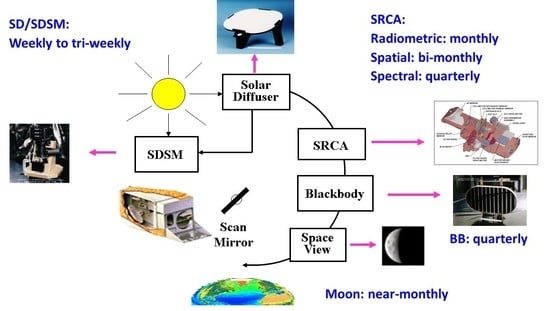
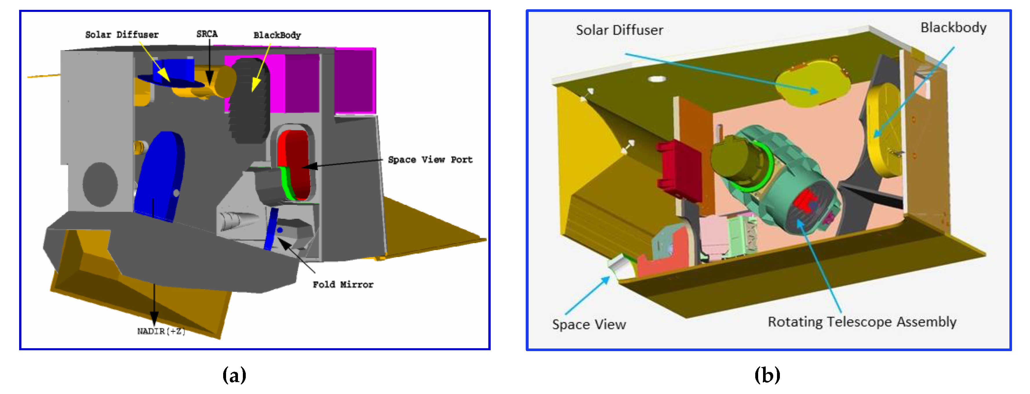
For both MODIS and VIIRS instruments, extensive pre-launch calibration activities were conducted using ground calibration sources and testing equipment to assess their performance against the design requirements. Key radiometric calibration activities are also performed on-orbit using the OBC, which include a solar diffuser (SD), a solar diffuser stability monitor (SDSM), a blackbody (BB), and a dedicated space view (SV) sector [13,14]. MODIS is also equipped with an onboard spectro-radiometric calibration assembly (SRCA), which was not included in VIIRS design. The SRCA is used primarily for spectral and spatial characterization. No SRCA in VIIRS was based on the MODIS experience that on-orbit changes in its spectral band RSR (center wavelength and bandwidth) have been very small and similar filter array design and builds are used in both MODIS and VIIRS. Other factors, such as instrument cost and weight, were also considered. The MODIS and VIIRS instruments and their OBCs are illustrated in Figure 1.
There have been many lessons learned from MODIS that have greatly benefited the design and operations of other remote sensing optical sensors, especially for the VIIRS instruments. Some of them are discussed and demonstrated in the following sections in terms of sensor pre-launch and on-orbit calibration and performance. Based on lessons from MODIS, it is extremely important to (1) build a comprehensive calibration program at the beginning of sensor design and testing; (2) establish a dedicated calibration team that can work closely with the sensor vendor and interact with the project and science team, and perform sensor calibration and characterization tasks through different phases of the mission, from pre-launch to on-orbit; (3) minimize and eliminate if possible, the crosstalk among detectors at the focal plane design and evaluation stage as its on-orbit characterization and correction could be very complicated and time-consuming; and (4) select a scanning mechanism that can minimize the effect due to optical degradation on sensor polarization sensitivity and RVS since accurate characterization of those parameters during on-orbit operations is extremely challenging.
3. Pre-Launch Calibration
Each sensor is developed and designed to achieve its mission objectives that are derived based on the needs of the science and user communities, technological advancements, and improved testing equipment and techniques. This results in a set of specified design requirements, such as sensor spectral coverage, spatial resolution, radiometric and geometric accuracy, together with various testing and performance verification requirements. This paper focuses on key issues related to sensor radiometric calibration.
Key objectives of pre-launch calibration and characterization include, but are not limited to (1) evaluating sensor performance under different operating conditions that might be experienced in space; (2) deriving calibration parameters that are needed to support sensor on-orbit calibration and its L1B calibration algorithm; and (3) establishing sensor calibration traceability and accuracy with reference measurements and comprehensive data analyses to help identify and quantify all contributors to the end-to-end calibration error budget. For typical multispectral optical sensors, the following are the key performance parameters that could have direct impact on radiometric calibration and data quality and are used to judge their compliance with the design and performance requirements:
- Relative spectral response (RSR), including both in-band (IB) and out-of-band (OOB)
- Signal-to-noise ratio (SNR) or noise equivalent temperature difference (NEdT)
- Dynamic range
- Nonlinearity
- Calibration accuracy (absolute and relative)
- Calibration stability (short- and long-term)
- Polarization responsivity
- Stray light rejection and crosstalk
- Response versus scan-angle (for scanning radiometer)
The MODIS and VIIRS instruments together will ultimately produce a continuous multispectral Earth remote sensing data set spanning approximately 40 years. The first step in assuring consistency in that multi-instrument, multi-decadal data set and, by inference, its ability to be used with data produced by other remote sensing instruments depends on the pre-launch calibration and characterization of those instruments against common, internationally recognized physical scales [13,15,16]. In general, the radiometric calibration is accomplished using sources, detectors, and artifacts with calibrations traceable to the physical scales maintained by national measurement laboratories (NMLs) and defined by the International System of units or SI. For MODIS and VIIRS, calibrations are traceable to standards maintained by the National Institute of Standards and Technology (NIST), the NML for the United States. For two MODIS and two VIIRS instruments currently on-orbit and the VIIRS instrument being readied for launch on the JPSS-2 satellite, comprehensive radiometric tests were performed in the laboratory to determine the coefficients used to convert the digital numbers produced by the instruments to radiance and to characterize overall instrument performance. These tests were performed in ambient and thermal vacuum conditions to simulate the anticipated range of on-orbit operating conditions and at the subsystem and system levels. Similar tests will also be performed on the VIIRS instruments aboard JPSS-3 and -4.
At the full instrument system level, pre-launch radiometric tests include the determination of sensor performance parameters listed above. For RSB radiometric tests, a Spherical Integrating Source-100 (SIS-100) was used. The SIS-100 is a 100 cm diameter integrating sphere source equipped with multiple quartz tungsten filament lamps of various wattages and a radiance monitor. Depending on the number and wattage of illuminated lamps, the uniform radiance output of the sphere covers a radiance range encompassing the brightest to dimmest scenes which will be viewed by the MODIS and VIIRS on-orbit. In addition to the SIS-100 calibration source, special measurement assemblies and ground test equipment were used for the RSR, RVS, and polarization characterization. The RVS and polarization characterization were performed at multiple scan angles.
The radiance calibration uncertainty of the SIS-100 used to calibrate the moderate resolution bands of MODIS and VIIRS and the imaging bands of VIIRS is ±5.0% (k = 1) for all lamp operating configurations with exception of the two lowest radiance levels below 0.41 µm and above 2.1 µm. For the VIIRS DNB calibration, the SIS-100 is equipped with a low radiance module containing two low wattage lamps. The radiance uncertainty for the DNB SIS-100 configuration is also ±5.0% (k = 1) over the 0.5-0.9 µm DNB spectral range.
The calibration of the SIS-100 is performed in the laboratory using an Analytical Spectral Devices (ASD) FieldSpec scanning spectroradiometer to transfer the measured radiance from a lamp-illuminated Spectralon diffuser to the SIS-100. The resulting calibration uncertainty of this approach has been fully quantified and validated using stable transfer radiometers to be better than ±3.0% (k = 1) [17]. SI traceability of this absolute spectral radiance calibration of the SIS-100 to NIST is achieved using a NIST traceable irradiance standard lamp to illuminate the Spectralon panel with bidirectional reflectance distribution function (BRDF) measured and validated against laboratory standard diffusers measured by NIST. The absolute radiance calibrated SIS-100 is used in combination with measurements of the relative spectral response (RSR) to determine the band-averaged absolute radiance responsivity (ASR). Figure 2 shows the MODIS RSB pre-launch radiance calibration traceability. Before 2000, NIST realized its spectral radiance scale using a source-based approach based on the absolute determination of the freezing temperature of gold [18,19]. As shown in Figure 2, a calibrated detector is used to assign the radiance temperature from a gold freezing point blackbody to lamp-1 operated at a temperature of 1337.3 K to match the radiance temperature of the gold blackbody at 654.6 nm and then to lamp-2 operated at the higher temperature of 1530 K via lamp-1. This is followed by extension of the radiance temperature scale to a variable temperature blackbody (VTBB) of high emissivity. The VTBB is used to assign the spectral radiance emitted from an integrating sphere source. The VTBB is outfitted with a precision aperture producing an irradiance source which can be used to calibrate the spectral irradiance from NIST primary irradiance standard lamps and the 1000 W FEL lamps which are used in MODIS calibrations. At the instrument vendor’s facility, a NIST-calibrated 1000 W FEL is used to illuminate a solar diffuser with known BRDF. The spectral radiance from the diffuser/lamp combination is transferred by the instrument vendor to the SIS-100, which is used for the MODIS and VIIRS RSB pre-launch calibration.
In 2000, NIST improved its source-based spectral radiance and irradiance scale realization with a detector-based approach. In this approach, the calibrated power responsivities of the transfer silicon trap detectors, determined using an absolute cryogenic radiometer (ACR), are transferred to a series of working standard detectors using a lamp/monchromator instrument and then to a set of filter radiometers (FRs). The FRs, comprising of filtered silicon photodiodes and precision apertures, are used to determine the radiance temperature scale of a High Temperature Blackbody (HTBB) source. The spectral radiance output of the HTBB is then transferred to the commercially available NIST 1000 W FEL irradiance standard lamps used in VIIRS RSB calibration. More details of this detector-based approach can be found in [20].
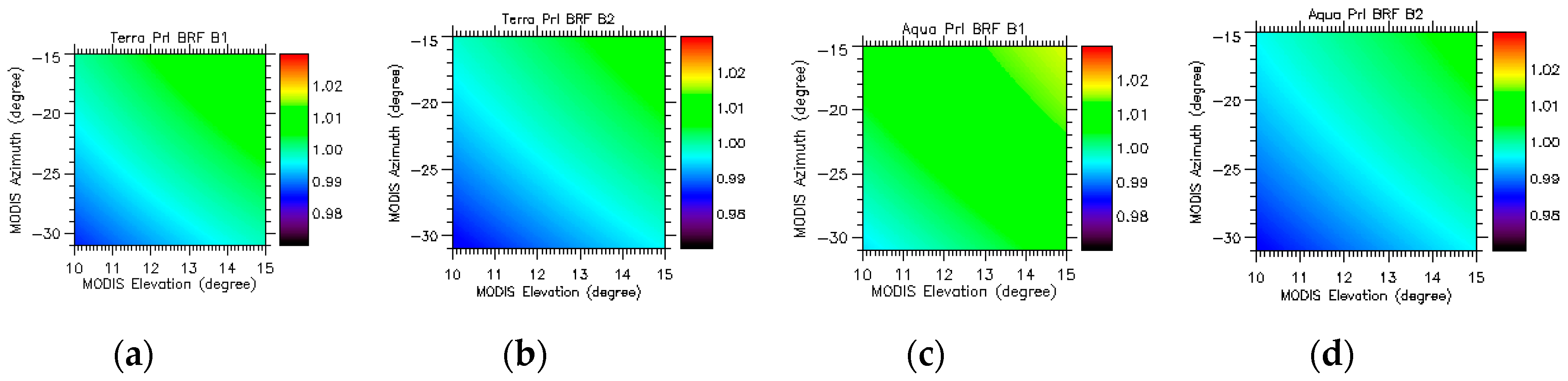
The MODIS and VIIRS pre-launch and on-orbit reflectance/radiance calibration traceability path is presented in Figure 3. The boxes in blue represent activities performed at NIST while the boxes in green represent activities performed at the instrument vendor’s facility. The activities in brown boxes are performed on-orbit. Briefly, a set of laboratory standard diffusers are provided to NIST by the satellite instrument vendor for measurements of their BRDF. For MODIS and SNPP VIIRS, NIST performed these measurements using their Special Tri-function Automated Reference Reflectometer (STARR) [21]. For NOAA-20 VIIRS, NIST measured the laboratory standard diffusers using their next-generation Robotic Optical Scatter Instrument (ROSI) [22]. These calibrated diffusers are used at the instrument vendor’s facility to validate the absolute BRDF calibration of the MODIS or VIIRS flight diffusers [23]. On-orbit, the flight diffuser is illuminated by the Sun and viewed by the MODIS or VIIRS instruments and periodically by an integrating sphere radiometer equipped with filtered detectors, referred to as the SDSM. The SDSM monitors spectral degradation in the diffuser spectral reflectance by ratioing its measurements of the Sun and the solar light reflected off the diffuser. In this manner, Earth scene BRDF at the top-of-the-atmosphere (TOA) is determined relative to the NIST traceable BRDF of the on-board diffuser, after correction for any reflectance degradation using data from the SDSM. The Earth scene radiance can be determined from the product of the Earth scene BRDF and the spectral solar irradiance. Shown in Figure 4 are examples of Terra and Aqua MODIS SD bi-directional reflectance factors (BRF; BRF = π·BRDF) for bands 1 (0.65 µm) and 2 (0.86 µm).
In addition to the SIS-100 radiance calibrations, the VIIRS instrument testing has incorporated a full-aperture spectral radiance calibration approach using intensity stabilized, tunable monochromatic lasers. In this approach, the output of the lasers is input to an integrating sphere equipped with trap reference detectors. Using this system, the sensor RSR and Absolute Spectral Responsivity (ASR) are determined by sequentially stepping the laser across all VIIRS bands while recording the simultaneous signals from the reference detectors and from VIIRS. The resulting monochromatic ASRs can be used to determine the responses of the instrument bands to broadband radiance sources directly, eliminating the need for calibrated broadband light sources such as the SIS-100. SI traceability of this absolute spectral radiance calibration is accomplished through NIST measurements of the ASRs of the trap reference detectors using their Spectral Irradiance and Radiance Responsivity Calibrations using the Uniform Sources (SIRCUS) laser system. Results derived from measurements using this full-aperture laser-based calibration approach indicate its potential capability to lower the absolute radiometric calibration uncertainty of VIIRS and other remote sensing instruments by an order of magnitude [24].
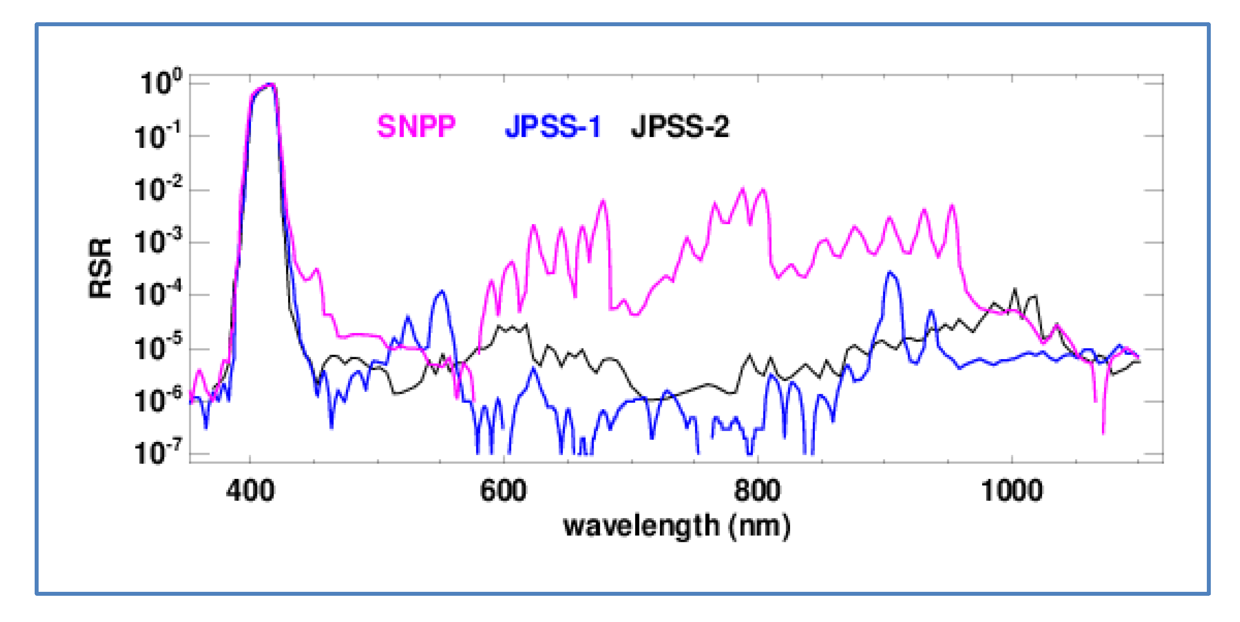
Figure 5 illustrates the RSR of VIIRS band M1 (0.41 µm) on S-NPP, JPSS-1 (or NOAA-20), and JPSS-2 satellites. Changes in filter design made in JPSS-1 and -2 have led to significant reduction of M1 out-of-band (OOB) responses. Compared to MODIS, the quality of VIIRS OOB RSR characterization has been greatly improved by including the use of the full-aperture laser-based approach [25]. The same test equipment has recently been used for the Landsat-9 Operational Land Imager (OLI) RSR measurements and will also be used for the spectral characterization of CLARREO PathFinder (CPF) instrument [26].
The pre-launch calibration of the MODIS and VIIRS TEB employs a large aperture blackbody calibration source (BCS) with high emissivity and accurately measured temperature operated in thermal vacuum conditions. The BCS is a trap-type, cavity blackbody with thermally controlled specular black surfaces. The radiance temperature scale for the BCS is established by the instrument builder using contact thermometry provided through the use of high precision platinum resistance thermometers (PRTs) with SI calibrations traceable to the NIST International Temperature Scale-90 (ITS-90) over the full 190 to 345 K BCS temperature operating range [27]. The emissivity of the BCS is computed to be 0.9996 using a geometric model of the BCS and knowledge of the bidirectional reflectance of the blackbody’s specular black surface. With knowledge of the effective BCS cavity temperature provided by a weighted average of the temperatures from the calibrated PRTs and the emissivity, the Planck radiation formula is used to determine the BCS emitted spectral radiance over the MODIS and VIIRS bands. Figure 6 shows the traceability of MODIS and VIIRS thermal infrared calibration, from pre-launch to on-orbit.
In an effort to validate the BCS radiance scale used in the MODIS (and later, VIIRS) calibrations, the NASA EOS project enlisted NIST to design, build, and test the Thermal Transfer Radiometer (TXR) and to deploy the TXR to instrument builder facilities [28]. The TXR is a liquid-nitrogen cooled, portable filter radiometer with two channels centered at 5 and 10 µm, both with bandwidths of approximately 1 µm. Prior to its deployment, the TXR absolute radiance temperature scale is transferred to the radiometer by having the TXR view the NIST Water Bath Blackbody (WBBB) at NIST’s Ambient Infrared Radiometry and Imaging (AIRI) facility [29,30]. The WBBB implements the NIST radiance temperature scale based upon the ITS-90 temperature scale. For lower temperatures, the radiance scale of the TXR was calibrated by placing the TXR in a NIST cryogenic vacuum chamber and having it view a large-area cryogenic blackbody with radiation temperature calibration tied to the NIST detector-based radiometric scale [31]. The radiance temperature scale of the TXR is maintained using a stable travelling blackbody, called the Check Source, between its calibration at NIST and its viewing the BCS.
The TEB radiometric calibration is performed at different environmental or instrument temperatures (such as RSB) and at different FPA temperatures. For a comprehensive testing, the BCS, located inside the thermal vacuum chamber, is operated over a range of temperatures. Detectors’ responses to BCS radiances at these temperatures are used to determine their key radiometric performance parameters, such as gains, dynamic range, nonlinearity, and NEdT. Figure 7 is an example of TEB detector responses to the BCS radiances for S-NPP VIIRS bands M13 and M14. The data were collected during sensor thermal vacuum testing at the nominal instrument temperature and with the cold FPA being set at 80 K. Different colors represent different detectors within a band. Only HAM side A responses are included.
The detector’s NEdT is also a key contributor to its calibration uncertainty. Demonstrated in Figure 8 is the NEdT performance for S-NPP and JPSS-1 VIIRS TEB in comparison with the specified requirements. Lower values of NEdT indicate better performance. Moreover, included in Figure 8 are their saturation temperatures. For both instruments, the TEB saturation temperatures are above the specified maximum temperatures, thus meeting the dynamic range design requirements.
4. On-Orbit Calibration
As described in Section 3, the MODIS and VIIRS calibration traceability were established through extensive pre-launch testing with measurements referenced to the national standards (at NIST) and transferred to the OBC, such as SD and BB. The OBC are operated regularly to maintain sensor on-orbit calibration accuracy and stability. Figure 9 is a schematic of MODIS on-orbit calibration and characterization approaches. As the scan mirror rotates, the sensor collects data consecutively from its SD, SRCA, BB, SV, and Earth View (EV) sectors.
The SD and SDSM are operated in tandem and used primarily for the RSB calibration. Over each mission lifetime, the SD/SDSM calibration frequency has been gradually reduced. The SRCA can be configured in three modes: Radiometric, spatial, and spectral. Their operational frequencies are also reduced gradually with time. The TEB calibration is performed on a scan-by-scan basis using the on-board BB with its temperature nominally controlled at 290 K for Terra MODIS and 285 K for Aqua MODIS. During each scan, the sensor also collects the SV data to measure the instrument background signals. Periodically, a BB warm-up and cool-down (WUCD) operation is performed, during which the BB temperatures vary from instrument ambient (approximately 270 K) to 315 K via electric heaters [32,33,34,35]. This operation enables the TEB detector nonlinearity to be monitored on-orbit via its responses to a broad range of BB temperatures and radiances. In addition to OBC, special calibration activities have been performed using spacecraft maneuvers, which include regularly scheduled lunar observations via spacecraft roll maneuvers. The data collected during yaw maneuvers have been used to characterize SD BRDF and its screen transmission functions, and data from the deep space pitch maneuvers have been used for the TEB RVS characterization [36,37,38]. To date, Terra has performed three pitch maneuvers.
The VIIRS on-orbit calibration methodologies and strategies, including calibration maneuvers, are nearly identical to what have been used for MODIS. Unlike MODIS, the VIIRS design did not have an on-board SRCA for its on-orbit spectral and spatial characterization. Due to this, lunar observations have been used for VIIRS spatial characterization. This approach was initially developed for MODIS and validated using results derived from its SRCA spatial characterization. It has been further extended and improved for the routine spatial characterization of VIIRS instruments [39,40].
The SD BRDF was characterized pre-launch and its on-orbit change is tracked by the on-board SDSM. For MODIS, an SD door is used to prevent the SD panel from unnecessary solar exposure when no calibration event is scheduled. For the high gain RSB, whose responses saturate when the SD is under direct solar illumination, a retractable attenuation screen is placed in front of the SD. The SD attenuation screen is a metal plate with many uniformly distributed pinholes and no on-orbit degradation of its transmission is expected. The SDSM is essentially a ratioing radiometer. It collects data with several filtered detectors embedded in a SIS covering wavelengths from 0.41 to 0.94 μm. It tracks the SD degradation using alternate measurements of direct sunlight and sunlight diffusely reflected from the SD panel. To match the SDSM Sun-view and SD-view responses, a fixed attenuation screen is mounted on the SDSM Sun-view port [29]. The VIIRS design, however, did not include a MODIS-like SD door in order to avoid potential failure during its on-orbit operations, and its SD calibration is performed in every orbit. Its SD screen is fixed permanently. The VIIRS SDSM has been operated more frequently than MODIS [41].
Figure 10 shows the SD on-orbit degradation for Aqua MODIS at 0.41, 0.55, and 0.86 µm and for S-NPP VIIRS at similar wavelengths. In general, the SD degrades faster at shorter wavelengths. This is consistent with what has been observed in most optical sensors that use calibration solar diffusers. With more frequent solar exposure, the S-NPP VIIRS SD has experienced much larger degradation than Aqua MODIS. For example, the S-NPP VIIRS SD has degraded more than 17% at 0.55 µm in 8.5 years, whereas Aqua MODIS SD has only degraded approximately 7.5% in 18 years. The Terra MODIS SD degradation rate at the beginning of mission was very similar to that of Aqua MODIS. Starting from July 2003, however, the Terra MODIS SD door has been fixed in the open position with its screen in the closed position. This change of SD calibration configuration has led to more frequent solar exposure on the SD surface and, therefore, more rapid SD degradation. Currently, the total SD degradation of Terra MODIS is much larger than that of Aqua MODIS. At 0.55 µm, Terra MODIS SD has seen a degradation of 25% in about 20.5 years. Operated in the same configuration and frequency, the NOAA-20 VIIRS SD degradation rate has been nearly identical to that of S-NPP.
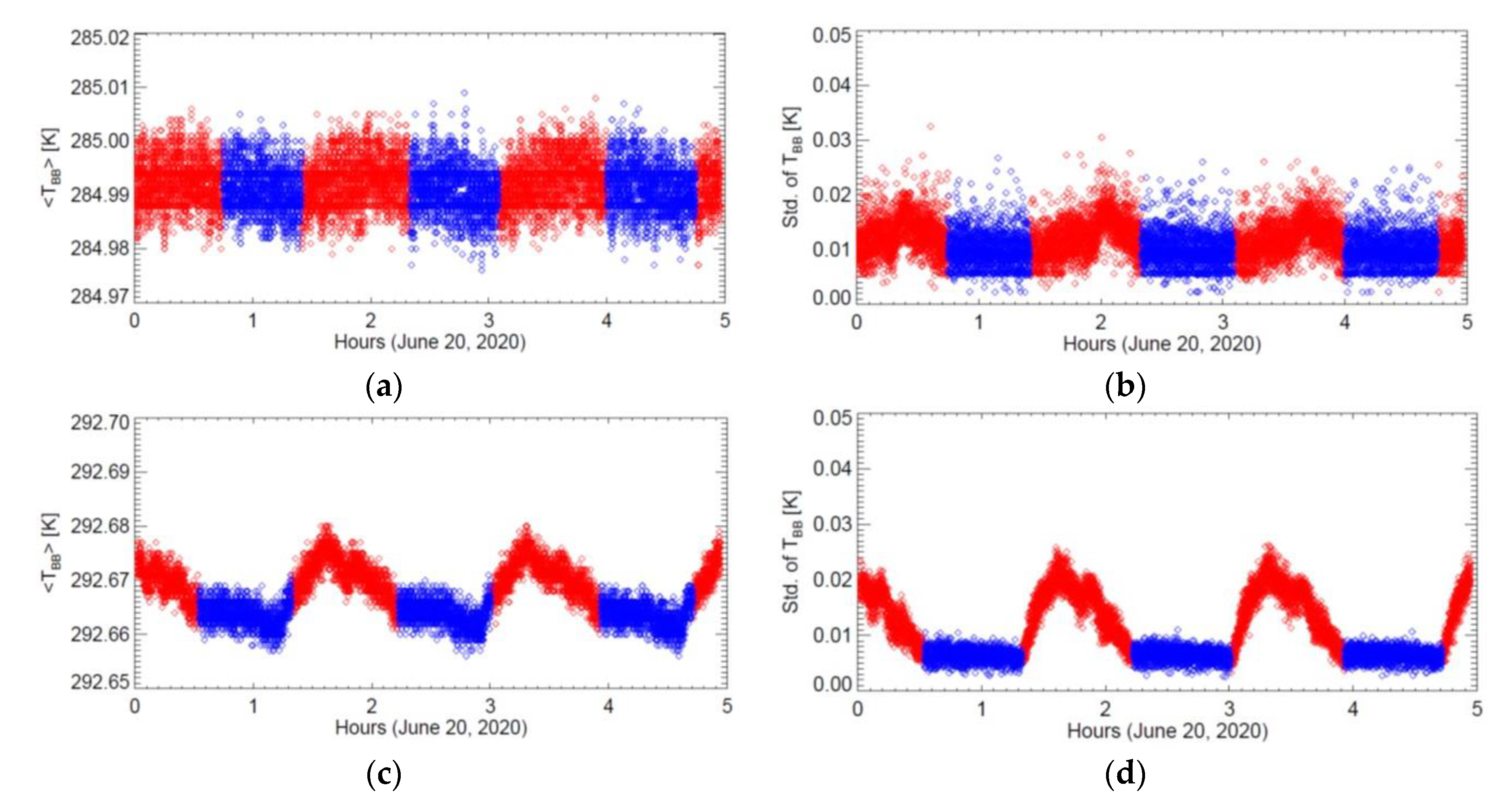
The TEB calibration traceability of both MODIS and VIIRS was established pre-launch using a ground-based BCS of high emissivity and temperature measurement accuracy and transferred to the on-board BB via simultaneous sensor views of the BCS and BB at various temperatures during thermal vacuum environmental testing. The MODIS on-board BB temperature is monitored by 12 thermistors, uniformly embedded in the back of the BB panel. Each of the BB thermistors was calibrated with reference to the NIST temperature scale to better than 0.05K. The average temperature from all 12 thermistors is used in the MODIS TEB calibration. The VIIRS BB design is nearly the same as the MODIS BB and uses six thermistors to measure its temperatures [34,42]. Illustrated in Figure 11 are the scan-by-scan BB temperatures and their standard deviations for Aqua MODIS, nominally controlled at 285.0 K, and S-NPP VIIRS, nominally controlled at 292.5 K, over a period of three successive orbits. The scan-by-scan variations of the Aqua MODIS BB temperatures are typically within ±0.01 K and standard deviations are less than 0.02 K, meeting the short-term stability design requirement (0.03 K). In general, Aqua MODIS BB short-term stability is slightly better than Terra MODIS, whose BB is nominally controlled at 290 K. For S-NPP VIIRS, the BB short-term stability is comparable to that of Aqua MODIS and its BB temperature standard deviations during nighttime orbits are noticeably smaller.
In addition to short-term stability, the MODIS and VIIRS BB have also demonstrated excellent long-term stability. For example, the long-term on-orbit drift of Aqua MODIS BB temperatures has been less than 5 mK for over 18 years and that of S-NPP VIIRS BB temperatures has been less than 10 mK over eight years. The long-term BB temperature drifts, though extremely small, are accurately monitored and accounted for in the TEB calibration algorithm, which also includes correction for changes in instrument temperatures and its background responses.
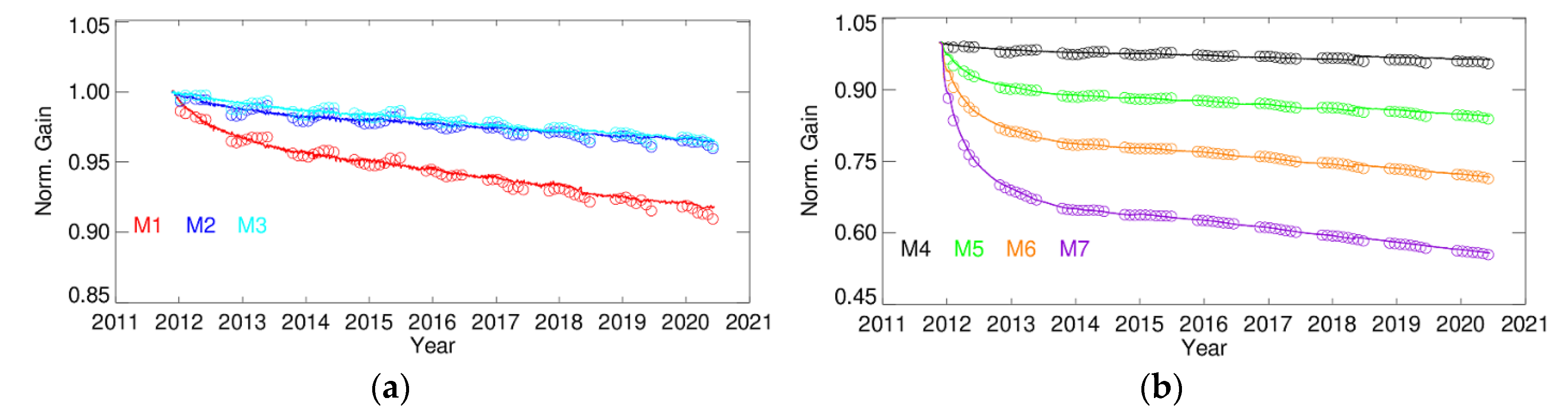
Both MODIS and VIIRS RSB use the same calibration strategies that include routine SD/SDSM measurements and regularly scheduled lunar observations [38,43]. For MODIS, lunar observations are made through the instrument SV port via spacecraft roll maneuvers at the same lunar phase angles. For VIIRS, lunar observations are made through an extension of the Earth view port via spacecraft roll maneuvers at nearly the same lunar phase as MODIS. For MODIS, the SD and lunar observations are made at different angles of incidence (AOI); and for VIIRS, both SD and lunar observations are made at the same AOI relative to its two-sided HAM. Shown in Figure 12 are the normalized gains of Aqua MODIS VIS bands (8, 9, and 10) derived from SD and lunar observations. In addition to wavelength, on-orbit changes in MODIS RSB gains are AOI dependent. This is because the system gains depend not only on the detector and electronic gains but also on the optical throughput. The largest change in the optical throughput is due to the change in the scan mirror’s reflectivity, which is wavelength and AOI dependent, and SD and lunar observations are made at different AOI of 50.2 and 11.2°, respectively. This is also the reason why the sensor’s RVS needs to be well-characterized over the entire EV range. For MODIS RSB, on-orbit changes of RVS are monitored using the SD and lunar observations, as well as the normalized (or relative) EV response trends at multiple AOIs [44]. In general, large changes are observed in the bands at short wavelengths. The changes in most NIR and SWIR bands are very small.
Figure 13 shows the normalized gains of S-NPP VIIRS VIS/NIR bands (M1-M7). The lines show the gains derived from the SD calibrations and the symbols show the results derived from lunar observations. For S-NPP VIIRS, the on-orbit changes in its VIS spectral band gains are much smaller than MODIS. However, the gains in several SNPP VIIRS NIR and SWIR bands have decreased much more rapidly at beginning of mission. The large decrease of detector gains in the NIR and SWIR region was due to optical degradation of the RTA primary mirrors, caused from the UV exposure of contaminated mirror surfaces [45]. In recent years, the S-NPP NIR and SWIR degradation rate has become much smaller, and overall RSB performance has become relatively stable. For NOAA-20 VIIRS, on-orbit changes in RSB gains have been extremely small at all wavelengths. To date, no noticeable on-orbit changes in the RSB RVS have been observed for both S-NPP and NOAA-20 VIIRS.
Both MODIS and VIIRS TEB use a similar quadratic calibration algorithm with dominant linear calibration coefficients or scaling factors determined on a scan-by-scan basis. Sensor responses during periodic BB WUCD are used to examine and update, if necessary, the offsets and nonlinear calibration coefficients. Details of MODIS and VIIRS TEB on-orbit calibration methodologies and examples of their performance can be found in several references [34,42,46].
For over 20 years, on-orbit changes in Terra MODIS TEB gains have been within 5% when operated in the same electronic configuration, except for the LWIR photovoltaic (PV) bands (27-30). Some of the detectors in the LWIR PV bands have been severely affected by electronic crosstalk that has gradually increased over time, especially following a spacecraft safe hold event in February 2016. Due to this, a crosstalk correction algorithm has been developed and implemented in the L1B, starting from its collection 6.1, to restore detector responses and minimize the crosstalk impact on calibration and science product quality [47]. Since launch, Aqua MODIS has been operated in the same configuration and on-orbit changes in its TEB long-term responses have been less than 4%. Small but noticeable seasonal variations in Aqua MODIS LWIR photoconductive (PC) bands have been observed since 2010, which are attributed to an increased fluctuation in its FPA temperatures due to a gradual decrease of the radiative cooler margin [34]. More recently, the LWIR FPA temperature fluctuations, and thus the variations of LWIR PC band responses, have been gradually reduced.
Figure 14 illustrates the S-NPP VIIRS TEB on-orbit gain trends derived from its BB measurements (band averaged; HAM side 1). From launch to present, the changes in S-NPP VIIRS TEB gains have been less than 1.0% except for I5, which has shown a total degradation of 2.4%. For NOAA-20 VIIRS launched in November 2017, an initial large degradation, up to 1.5% of the gain in its LWIR bands (e.g., I5 and M16), was observed. The root cause of this degraded performance was identified as the icing in the optical path within the LWIR FPA dewar. Following an outgas performed in March 2018, the gains in the LWIR bands all returned to their pre-icing levels. Since then, the TEB gain trends of NOAA-20 VIIRS have been very stable and nearly identical to that of S-NPP, including the behavior of band I5 with the largest gain degradation [46].
Most detectors in MODIS and VIIRS spectral bands have continued to function well on-orbit, showing excellent and stable noise characterization performance. Each MODIS has a total of 490 individual detectors, 330 for the RSB and 160 for the TEB. Throughout their missions of more than 20 and 18 years, respectively, Terra and Aqua MODIS each have only had less than 10 new noisy and inoperable detectors. For S-NPP VIIRS, there have been no new noisy or inoperable detectors since its launch in November 2011. Table 3 is a summary of its detector pre-launch and on-orbit SNR and NEdT performance. The SNR and NEdT requirements are specified at typical scene radiances (M1-M11) and temperatures (M12-M16). For RSB, the SNR are derived from the detector responses to the SD at various solar illuminating angles and thus at different signal levels. For TEB, the NEdT are computed using the detector responses at different BB temperatures during BB WUCD. The measured SNR and NEdT at typical radiances (or temperatures) are used to access detector noise characterization performance. The performance results are expressed using ratios of the measured SNR (or NEdT) to the specified SNR (or NEdT). For RSB bands M1-M11, ratios larger than 1 indicate that the actual performance is better than specified requirements. Similarly, ratios less than 1 correspond to good performance for the TEB bands M12-M16.
On-orbit changes in sensor characteristics are constantly monitored and corrected via calibration LUT updates and, if necessary, algorithm modifications. Since launch, several MODIS data collections have been generated and distributed to users worldwide. Table 4 provides a brief summary of Terra MODIS L1B data collections, from launch to present, and major calibration updates associated with each data collection. Collection 2 is the first MODIS on-orbit data collection and collection 6.1 is the latest data collection. Aqua MODIS started from collection 3 in mid-2002. Its follow-on data collections are closely synchronized with Terra MODIS and, as expected, most of the calibration updates made in Terra MODIS have also applied to Aqua MOSIS. More details of MODIS L1B algorithm (code) changes and calibration LUT updates can be found in [48]
5. Challenges and Future Improvements
There have been many advancements and lessons learned through different phases of MODIS and VIIRS development, pre-launch testing, and on-orbit operations to better characterize, assess, and improve their performance; and to meet their overall science objectives. Albeit extensive pre-launch and on-orbit calibration and characterization activities and efforts, challenges still exist to establish and maintain calibration traceability, accuracy, and stability. In the reflective solar spectral region, an unbroken and highly reliable calibration transfer from pre-launch to on-orbit remains to be a major challenge. In general, the error associated with SD BRDF characterization is the largest contributor to the RSB on-orbit calibration uncertainty [49,50]. The use of the SD attenuation screen adds another key error term, which depends on how accurately the screen transmission can be characterized at different solar illuminating and sensor viewing geometries. On-orbit yaw maneuvers have been performed for MODIS and VIIRS to help characterize the SD BRDF and SD screen transmission function. Unlike VIIRS, the MODIS SD screen can be operated in both “open” and “closed” positions, thus its screen transmission or vignetting function can be characterized absolutely. Only the relative shape of SD BRDF can be characterized using data collected during yaw maneuvers and compared with pre-launch results.
Experience and lessons learned from MODIS spectral and polarization characterization have led to the development and use of improved ground testing equipment and approaches in VIIRS testing. The tunable, intensity stabilized laser approach described in Section 3 moves SI traceability of radiometric calibration from the SIS-100 source-based system to a reference trap detector-based system while producing lower overall calibration uncertainties. For the calibration of absolute spectral radiance responsivities of remote sensing instruments, systems incorporating supercontinuum (i.e., white light) laser sources (SLS) with laser line tunable filters (LLTF) are being developed [51,52]. In these systems, the intensity stabilized, monochromatic output of a tunable supercontinuum laser with LLTF is input to an integrating sphere whose output is monitored using trap reference detectors calibrated for absolute spectral radiance responsivity. In one approach, the satellite instrument under test directly views the monitored, stabilized, tunable output from the integrating sphere in a similar fashion to that currently used in the laser-based approach described in Section 3 [52]. In a second approach, a stable and fully characterized transfer standard spectrometer views the monitored, stabilized, tunable sphere output and transfers that radiance calibration scale to a lamp-based calibration source such as the SIS-100 [53]. In both approaches, SI traceability of absolute radiance calibration is achieved through calibration of the sphere trap reference detectors against the absolute cryogenic radiometers. When fully commissioned, these SLS and LLTF-based approaches could potentially achieve absolute calibration uncertainties approximately three times lower than those realized using conventional source-based approaches while substantially reducing overall calibration times.
The laboratory determination of the BRDF of the solar diffusers used in the pre-launch and on-orbit RSB calibration of the MODIS and VIIRS instruments, while conceptually simple, still remains challenging. The SD material of choice of all the MODIS and VIIRS instruments is Spectralon, a pressed and sintered polytetrafluoroethylene (PTFE) material. A NASA-sponsored and NIST- coordinated BRDF round-robin held in 2000 included satellite instrument builders, government laboratories, and a university laboratory, all with ties to the EOS program. The round-robin employed a variety of diffuser targets, one of which was Spectralon. The round-robin results showed that the participants were capable of making spectral BRDF measurements on different diffuse materials over a range of incident and scatter angles to within 2% of those made by NIST. However, in 2010 laboratory measurements of Spectralon BRDF by the VIIRS instrument builder, Raytheon El Segundo, were found to exhibit a significant dependence on azimuthal angle. This “clocking effect,” which varied from sample to sample, could result in an additional 2% error in the laboratory measured, and by inference on-orbit, BRDF particularly at large incident and scatter angles. This discovery has led to additional requirements on the material scatter properties of Spectralon and more extensive BRDF characterizations of Spectralon diffusers than what were performed previously.
On-orbit RSB calibration challenges also include accurate characterization of on-orbit changes in the SD BRDF and detector responses that strongly depend on wavelength and AOI. In Terra MODIS, the EV response trends have shown that the instrument polarization sensitivity also experienced large on-orbit changes in a few short wavelength spectral bands at large AOI, especially after 2007. This is illustrated in Figure 15 for band 8 (the shortest wavelength band) using the normalized reflectance trends at two different AOI over select desert sites. On-orbit changes in the polarization sensitivity, if not corrected, could significantly increase the radiometric calibration uncertainty, and thus affect the science product quality. Accordingly, the NASA ocean group has developed and implemented an approach to derive the polarization parameters over ocean targets for select Terra MODIS VIS bands. This approach uses the SeaWiFS (1997-2010) and then Aqua MODIS (2002-present) as a combined reference [54,55]. Similar to ocean color products, several land and atmosphere products that use the short wavelength VIS bands have also applied the polarization correction in their retrieval algorithms. An alternative approach has also been developed by the MODIS calibration team to derive the polarization correction parameters using the top-of-atmosphere (TOA) reflectances over select desert sites at different AOI [56]. Starting from collection 7 (C7), the Terra MODIS will use polarization corrected long-term reflectance trends over desert sites for its VIS band RVS characterization. As shown in Figure 15, the polarization-corrected trends have significantly reduced oscillations in the later years of Terra mission and can help maintain high quality RVS characterization [57]. To date, no changes in polarization sensitivity have been seen in Aqua MODIS and VIIRS.
For thermal emissive calibration, the well-designed on-board BBs have been effective in ensuring sensor on-orbit calibration traceability and accuracy exhibiting no on-orbit changes in emissivity while maintaining temperature measurement accuracy. Future design enhancement of the on-board BB could be made by including phase transition cells for absolute temperature reference and emissivity monitoring capability [58]. Located on the temperature controlled cold FPA, most TEB spectral bands only experience small changes. For Terra MODIS, however, on-orbit changes in its LWIR PV band electronic crosstalk are a major concern, which requires dedicated efforts to characterize and derive the correction coefficients implemented in the L1B calibration algorithms, and to minimize the crosstalk impact on the science product quality [47]. As expected, there are more challenging issues for missions (sensors) that have continued to operate significantly beyond their design lifetime.
In addition to radiometrically calibrated and geo-located reflectance and/or radiance, MODIS L1B data products include a pixel level uncertainty index (UI), which is converted from the calibration uncertainty for each EV pixel. For RSB, it includes the uncertainties of SD BRDF and on-orbit degradation, detector gain (calibration coefficients), RVS, and SNR (at the pixel signal level). For the TEB, key contributors include uncertainties of the BB emissivity and temperature, detector gains and NEdT, and RVS [59]. Figure 16 shows the on-orbit calibration uncertainties in reflectance (k = 1) for Aqua MODIS RSB at nadir AOI and typical radiance levels. Most bands continue to meet the 2% calibration requirement in reflectance (k = 1). Moreover, included in Figure 16 are the calibration uncertainties for Aqua MODIS TEB at nadir AOI and typical radiance levels. Not included is band 21, which was designed for fire detection. All TEB bands continue to meet their calibration requirements for Aqua MODIS. The UI has been considered but not yet implemented as part of the L1B or SDR (sensor data records) for the SNPP and NOAA-20 VIIRS.
Ongoing efforts towards making highly accurate measurements of lunar irradiance and improving absolute accuracy of the lunar models could make the Moon an alternative, stable target (or source) for sensor on-orbit calibration. Currently, the lunar observations are primarily used for sensor calibration stability monitoring and calibration inter-comparison. Use of the Moon as a viable absolute calibration source requires that either the measured or modeled spectral irradiance or radiance of the Moon as a function of lunar phase and libration be known with an uncertainty of less than 1% (k = 1). Current models of lunar spectral irradiance have absolute uncertainties that are five to ten times higher [60]. As a result, accurate determination of the lunar spectral irradiance has truly become an international effort. In 2013, NIST reported the acquisition of spectral lunar irradiances in the visible wavelength region using their LUnar Spectral Irradiance (LUSI) instrument, a telescope and a non-imaging spectrograph, with uncertainties less than 1.0% [61]. In 2021, a LUSI instrument is scheduled to be operating from the observatory on Mauna Loa in Hawaii, at an elevation of 3.3 km above the majority of the atmosphere. In 2018 and 2019, an ER-2 airborne version of the NIST system, airLUSI, successfully flew in two campaigns acquiring lunar images in the visible wavelength region [62]. The European Space Agency (ESA) currently operates a solar photometer on the slopes of Mount Teide in Tenerife, Canary Islands, designed to observe the full lunar disc [63]. On-orbit, the Pleiades high resolution instruments have acquired an extensive database of stellar and lunar images used to correct and improve the ROLO model [64].
New missions designed for climate measurements with much high-accuracy SI traceability, such as NASA’s Climate Absolute Radiance and Refractivity Observatory (CLARREO) and ESA’s Traceable Radiometry Underpinning Terrestrial and Helio Studies (TRUTHS) missions, will improve the calibration quality of other on-orbit sensors using a simultaneous overpass comparison approach [65,66,67,68]. CLARREO and TRUTHS will initiate the most accurate benchmark climate record to date and will provide an SI-traceable, on-orbit calibration standard for sensors such as MODIS and VIIRS.
6. Conclusions
MODIS and VIIRS instruments were designed and built by the same instrument vendor. A comprehensive and vigorous testing program established to support and guide the sensor pre-launch calibration and characterization has continuously evolved and improved over the years employing new methodologies, techniques, and upgraded testing equipment. Independent test data analyses and performance assessments made by the sensor vendor and government-led calibration support team are also a key component of this testing program. High-quality measurements from both MODIS and VIIRS instruments, together with their extensive pre-launch to post-launch calibration and characterization efforts, have contributed to the remote sensing community and users worldwide to advance their studies of the Earth’s system and its key environmental parameters. The unprecedented long-term data records from both MODIS and VIIRS observations, which could span over four decades, will also significantly benefit the space-based climate observing system. Apart from a brief review of MODIS and VIIRS calibration history, this paper provides an overview of calibration approaches and strategies applied to establish and maintain their calibration traceability and accuracy, and an illustration of their pre-launch and on-orbit calibration performance via examples derived from various calibration targets or sources. As outlined in this paper, MODIS and VIIRS sensor calibration has been an ongoing process extending well beyond predicted mission lifetimes. Continuing efforts will be made to address remaining or new challenges in MODIS and VIIRS calibration and characterization and to maintain their data quality. Potential and further improvements of MODIS and VIIRS calibration and data quality could be accomplished by inter-calibrating with highly accurate and SI traceable climate missions or sensors, such as CLARREO PathFinder and TRUTHS currently under development.
Author Contributions
Conceptualization, X.X. and J.J.B.; methodology, X.X. and J.J.B.; formal analysis, X.X. and J.J.B.; investigation, X.X. and J.J.B.; writing—original draft preparation, X.X. and J.J.B.; writing—review and editing, X.X. and J.J.B. All authors have read and agreed to the published version of the manuscript.
Funding
This research received no external funding.
Acknowledgments
The authors would like to thank contributions made by the instrument vendor throughout MODIS and VIIRS missions, the Terra and Aqua MODIS Project, and the JPSS program. We would like to thank Amit Angal and other members of the MODIS and VIIRS characterization support teams for their technical assistance.
Conflicts of Interest
The authors declare no conflict of interest.
References
- Salomonson, V.; Barnes, W.; Maymon, P.; Montgomery, H.; Ostrow, H. MODIS: Advanced facility instrument for studies of the Earth as a system. IEEE Trans. Geosci. Remote Sens. 1989, 27, 145–153. [Google Scholar] [CrossRef]
- Barnes, W.; Salomonson, V. MODIS: A global image spectroradiometer for the Earth Observing System. Crit. Rev. Opt. Sci. Technol. 1993, CR47, 285–307. [Google Scholar]
- Salomonson, V.; Barnes, W.; Xiong, X.; Kempler, S.; Masuoka, E. An overview of the Earth Observing System MODIS instrument and associated data systems performance. Proc. IGARSS 2002, 2, 1174–1176. [Google Scholar]
- Xiong, X.; King, M.; Salomonson, V.; Barnes, W.; Wenny, B.; Angal, A.; Wu, A.; Madhavan, S.; Link, D. Moderate resolution imaging spectroradiometer on terra and aqua missions. In Optical Payloads for Space Missions; Quain, S., Ed.; John Wiley & Sons, Ltd.: Hobojen, NJ, USA, 2015. [Google Scholar]
- Justice, C.; Vermote, E.; Townshend, J.; Defries, R.; Roy, D.; Hall, D.; Salomonson, V.; Privette, J.; Riggs, G.; Strahler, A.; et al. The Moderate Resolution imaging spectroradiometer (MODIS): Land remote sensing for global change research. IEEE Trans. Geosci. Remote Sens. 1998, 36, 1228–1249. [Google Scholar] [CrossRef] [Green Version]
- Esaias, E.; Abbott, M.; Barton, I.; Brown, O.; Campbell, J.; Carder, K.; Clark, D.; Evans, R.; Hoge, F.; Gordon, H.; et al. An overview of modis capabilities for ocean science observations. IEEE Trans. Geosci. Remote Sens. 1998, 36, 1250–1265. [Google Scholar] [CrossRef] [Green Version]
- King, M.; Menzel, P.; Kaufman, Y.; Tanre, D.; Gao, B.; Platnick, S.; Ackerman, S.; Remer, L.; Pincus, R.; Hubanks, P. Cloud and aerosol properties, precipitable water, and profiles of temperature and water vapor from MODIS. IEEE Trans. Geosci. Remote Sens. 2003, 41, 442–458. [Google Scholar] [CrossRef] [Green Version]
- Parkinson, C. Aqua: An earth-observing satellite mission to examine water and other climate variables. IEEE Trans. Geosci. Remote Sens. 2003, 41, 173–183. [Google Scholar] [CrossRef]
- Lee, T.; Nelson, S.; Dills, P.; Riishojgaard, L.; Jones, A.; Li, L.; Miller, S.; Flynn, L.; Jedlovec, G.; McCarty, W.; et al. NPOESS: Next-Generation operational global earth observations. Bull. Amer. Meteor. Soc. 2010, 91, 727–740. [Google Scholar] [CrossRef] [Green Version]
- Ardanuy, P.; Schueler, C.F.; Miller, S.W.; Kealy, P.S.; Cota, S.A.; Haas, J.K.; Welsch, C. NPOESS VIIRS Design process. Proc. SPIE 2002, 4483, 22–34. [Google Scholar]
- Schueler, C.F.; Clement, E.; Ardanuy, P.; Welsh, C.; DeLuccia, F.; Swenson, H. NPOESS VIIRS sensor design overview. Proc. SPIE 2002, 4483, 11–23. [Google Scholar]
- Lee, T.; Miller, S.; Schueler, C.; Miller, S. NASA MODIS previews NPOESS VIIRS capabilities. Weather Forecast. 2006, 21, 649–655. [Google Scholar] [CrossRef]
- Barnes, W.; Pagano, T.; Salomonson, V. Prelaunch characteristics of the moderate resolution imaging spectroradiometer (MODIS) on EOS-AM1. IEEE Trans. Geosci. Remote Sens. 1998, 36, 1088–1100. [Google Scholar] [CrossRef] [Green Version]
- Xiong, X.; Chiang, K.; Esposito, J.; Guenther, B.; Barnes, W. MODIS On-orbit calibration and characterization. Metrologia 2003, 40, 89–92. [Google Scholar] [CrossRef]
- Oudrari, H.; Mcintire, J.; Xiong, X.; Butler, J.; Lee, S.; Lei, N.; Schwarting, T.; Sun, J. Prelaunch radiometric characterization and calibration of the S-NPP VIIRS sensor. IEEE Trans. Geosci. Remote Sens. 2015, 53, 2195–2210. [Google Scholar] [CrossRef]
- Oudrari, H.; McIntire, J.; Xiong, X.; Butler, J.; Ji, Q.; Schwarting, T.; Angal, A. An overall assessment of JPSS-2 VIIRS radiometric performance based on pre-launch testing. Remote Sens. 2018, 10, 1921. [Google Scholar] [CrossRef] [Green Version]
- Butler, J.; Brown, S.; Saunders, R.; Johnson, B.; Biggar, S.; Zalewski, E.; Markham, B.; Gracey, P.; Young, J.; Barnes, R. Radiometric measurement comparison on the integrating sphere source used to calibrate the Moderate Resolution Imaging Spectroradiometer (MODIS) and the Landsat 7 enhanced thematic Mapper Plus (ETM+). J. Res. NIST 2003, 108, 199–228. [Google Scholar] [CrossRef]
- Mielenz, K.; Saunders, R.; Shumaker, J. Spectroradiometric Determination of the freezing temperature of gold. J. Res. Natl. Inst. Stand. Technol. 1990, 95, 49–67. [Google Scholar] [CrossRef]
- Mielenz, K.; Saunders, R.; Parr, A.; Hsia, J. The 1990 NIST scales of thermal radiometry. J. Res. Natl. Inst. Stand. Technol. 1990, 95, 621–629. [Google Scholar] [CrossRef]
- Yoon, H.; Gibson, C.; Barnes, P. Realization of the national institute of standards and technology detector-based spectral irradiance scale. Appl. Opt. 2002, 41, 5879–5890. [Google Scholar] [CrossRef]
- Proctor, J.; Barnes, P. NIST high accuracy reference reflectometer-spectrophotometer. J. Res. Natl. Inst. Stand. Technol. 1996, 101, 619–627. [Google Scholar] [CrossRef]
- Patrick, H.; Zarobila, C.; Germer, T. The NIST Robotic Optical Scatter Instrument (ROSI) and its application to BRDF measurements of diffuse reflectance standards for remote sensing. Proc. SPIE 2013, 8866, 886615. [Google Scholar]
- Murgai, V.; Johnson, L.; Moskun, E. BRDF Characterization of diffuser for JPSS J1 using PASCAL. Proc. SPIE 2014, 9218, 9218. [Google Scholar]
- Barnes, R.; Brown, S.; Lykke, K.; Guenther, B.; Butler, J.; Schwarting, T.; Turpie, K.; Moyer, D.; DeLuccia, F.; Moeller, C. Comparison of two methodologies for calibrating satellite instruments in the visible and near-infrared. Appl. Opt. 2015, 54, 10376–10396. [Google Scholar] [CrossRef] [PubMed] [Green Version]
- Moeller, C.; Schwarting, T.; McIntire, J.; Moyer, D. JPSS-1 VIIRS pre-launch spectral characterization and performance. Proc. SPIE 2015, 9607, 960711. [Google Scholar]
- Barsi, J.; Markham, B.; McCorkel, J.; McAndrew, B.; Donley, E.; Morland, E.; Pharr, J.; Rodriguez, M.; Shuman, T.; Sushkov, A.; et al. The Operational Land Imager-2: Prelaunch spectral characterization. Proc. SPIE 2019, 11127, 111270B. [Google Scholar]
- Preston-Thomas, H. The international temperature scale of 1990 (ITS-90). Metrologia 1990, 27, 3–10. [Google Scholar] [CrossRef]
- Rice, J.; Johnson, B. The NIST EOS thermal-infrared transfer radiometer. Metrologia 1998, 35, 505–509. [Google Scholar] [CrossRef]
- Mekhontsev, S.; Khromchenko, V.; Hanssen, L. NIST radiance temperature and infrared spectral radiance scales at near-ambient temperatures. Int. J. Thermophys. 2008, 29, 1026–1040. [Google Scholar] [CrossRef]
- Fowler, J. A third generation water bath based blackbody source. J. Res. NIST 1995, 100, 591–599. [Google Scholar] [CrossRef]
- Fowler, J.; Johnson, B.; Rice, J.; Lorentz, S. The new cryogenic vacuum chamber and black-body source for infrared calibrations at the NIST’s FARCAL facility. Metrologia 1998, 35, 323. [Google Scholar] [CrossRef]
- Xiong, X.; Che, N.; Barnes, W. Terra MODIS On-orbit spatial characterization and performance. IEEE Trans. Geosci. Remote Sens. 2005, 43, 355–365. [Google Scholar] [CrossRef]
- Xiong, X.; Che, N.; Barnes, W. Terra MODIS On-orbit spectral characterization and performance. IEEE Trans. Geosci. Remote Sens. 2006, 44, 2198–2206. [Google Scholar] [CrossRef]
- Xiong, X.; Wu, A.; Wenny, B.N.; Madhavan, S.; Wang, Z.; Li, Y.; Chen, N.; Barnes, W.; Salomonson, V. Terra and aqua MODIS thermal emissive bands on-orbit calibration and performance. IEEE Trans. Geosci. Remote Sens. 2015, 53, 5709–5721. [Google Scholar] [CrossRef]
- Xiong, X.; Angal, A.; Twedt, K.A.; Chen, H.; Link, D.; Geng, X.; Aldoretta, E.; Mu, Q. MODIS reflective solar bands on-orbit calibration and performance. IEEE Trans. Geosci. Rem. Sens. 2019, 57, 6355–6371. [Google Scholar] [CrossRef]
- Xiong, X.; Sun, J.; Esposito, J.; Liu, X.; Barnes, W.; Guenther, B. On-orbit characterization of a solar diffuser’s bidirectional reflectance factor using spacecraft maneuvers. Proc. SPIE 2003, 5151, 75–383. [Google Scholar]
- Xiong, X.; Salomonson, V.V.; Chiang, K.; Wu, A.; Guenther, B.; Barnes, W.L. On-orbit characterization of RVS for MODIS thermal emissive bands. Proc. SPIE 2005, 5652, 210–218. [Google Scholar]
- Sun, J.; Xiong, X.; Barnes, W.; Guenther, B. MODIS reflective solar bands on-orbit lunar calibration. IEEE Trans. Geosci. Remote Sens. 2007, 45, 2383–2393. [Google Scholar] [CrossRef]
- Xiong, X.; Sun, J.; Xiong, S.; Barnes, W.L. Using the moon for MODIS On-orbit spatial characterization. Proc. SPIE 2004, 5234, 480–487. [Google Scholar]
- Wang, Z.; Xiong, X.; Li, Y. Improved VIIRS band-to-band registration characterization based on lunar observation. Remote Sens. 2016, 8, 27. [Google Scholar] [CrossRef] [Green Version]
- Xiong, X.; Butler, J.; Chiang, K.; Efremova, B.; Fulbright, J.; Lei, N.; McIntire, J.; Oudrari, H.; Wang, Z.; Wu, A. Assessment of S-NPP VIIRS on-orbit radiometric calibration and performance. Remote Sens. 2016, 8, 84. [Google Scholar] [CrossRef] [Green Version]
- Efremova, B.; Mcintire, J.; Moyer, D.; Wu, A.; Xiong, X. S-NPP VIIRS thermal emissive bands on-orbit calibration and performance. J. Geophys. Res. 2014, 119, 10859–10875. [Google Scholar] [CrossRef] [Green Version]
- Xiong, X.; Sun, J.; Fulbright, J.; Wang, Z.; Butler, J. Lunar calibration and performance for S-NPP VIIRS reflective solar bands. IEEE Trans. Geosci. Remote Sens. 2016, 54, 1052–1061. [Google Scholar] [CrossRef]
- Sun, J.; Xiong, X.; Angal, A.; Chen, H.; Wu, A.; Geng, X. Time-Dependent response versus scan angle for MODIS reflective solar bands. IEEE Trans. Geosci. Remote Sens. 2014, 52, 3159–3174. [Google Scholar] [CrossRef] [Green Version]
- Barrie, J.; Fuqua, P.; Meshishnek, M.; Ciofalo, M.; Chu, C.; Chaney, J.; Moision, R.; Graziani, L. Root cause determination of on-orbit degradation of the VIIRS rotating telescope assembly. Proc. SPIE 2012, 8510, 851009. [Google Scholar]
- Li, Y.; Xiong, X.; McIntire, J.; Angal, A.; Gusev, S.; Chiang, K. Early calibration and performance assessments of NOAA-20 VIIRS thermal emissive bands. IEEE Trans. Geosci. Remote Sens. 2019, 57, 9242–9251. [Google Scholar] [CrossRef]
- Wilson, T.; Wu, A.; Shrestha, A.; Geng, X.; Wang, Z.; Moeller, C.; Frey, R.; Xiong, X. Development and implementation of an electronic crosstalk correction for bands 27-30 in terra MODIS collection 6. Remote Sens. 2017, 9, 569. [Google Scholar] [CrossRef] [Green Version]
- Toller, G.; Xiong, X.; Sun, J.; Wenny, B.N.; Geng, X.; Kuyper, J.; Angal, A.; Chen, H.; Madhavan, S.; Wu, A. Terra and aqua moderate-resolution imaging spectroradiometer collection 6 level 1b algorithm. J. Appl. Remote Sens. 2013, 7, 073557. [Google Scholar] [CrossRef]
- Early, E.; Barnes, P.; Johnson, B.; Butler, J.; Bruegge, C.; Biggar, S.; Spyak, P.; Pavlov, M. Bidirectional reflectance round-robin in support of the earth observing system program. J. Atmos. Ocean. Technol. 2000, 17, 1077–1091. [Google Scholar] [CrossRef]
- Murgai, V.; Nixt, J.; Moskun, E.; Jones, C.; Payton, C.; Cdbaca, J. PASCAL: Instrument for accurate, precise calibration of lambertian materials. Proc. SPIE 2010, 7792, 77920X. [Google Scholar]
- Levick, A.; Greenwell, C.; Irland, J.; Woolliams, E.; Goodman, T.; Bialek, A.; Fox, N. A spectral radiance source based on a supercontinuum laser and wavelength tunable bandpass filter: The spectrally tuneable absolute irradiance and radiance source. Appl. Opt. 2014, 53, 3508–3519. [Google Scholar] [CrossRef]
- Woodward, J.; Smith, A.; Jenkins, C.; Lin, C.; Brown, S.; Lykke, K. Supercontinuum sources for metrology. Metrologia 2009, 46, S277–S282. [Google Scholar] [CrossRef]
- Brown, S.; National Institute of Standards and Technology, Gaithersburg, MD, USA. Personal communication, 2019.
- Kwiatkowska, E.; Franz, B.A.; Meister, G.; McClain, C.; Xiong, X. Cross calibration of ocean-color bands from moderate resolution imaging spectroradiometer on terra platform. Appl. Opt. 2008, 47, 6796–6810. [Google Scholar] [CrossRef] [PubMed]
- Meister, G.; Eplee, R.; Franz, B. Corrections to MODIS Terra calibration and polarization trending derived from ocean color products. Proc. SPIE 2014, 9218, 92180V. [Google Scholar]
- Wu, A.; Geng, X.; Wald, A.; Angal, A.; Xiong, X. Assessment of Terra MODIS on-orbit polarization sensitivity using pseudo invariant desert sites. IEEE Trans. Geosci. Remote Sens. 2017, 55, 4168–4176. [Google Scholar] [CrossRef]
- Angal, A.; Geng, X.; Xiong, X.; Twedt, K.; Wu, A.; Link, D.; Aldoretta, E. On-orbit calibration of Terra MODIS VIS bands using polarization-corrected desert observations. IEEE Trans. Geosci. Remote Sens. 2020, 12, 1915. [Google Scholar] [CrossRef]
- Best, F.; Adler, D.; Pettersen, C.; Revercomb, H.; Gero, P.; Taylor, J.; Knuteson, R.; Perepezko, J. On-orbit absolute radiance standard for the next generation of IR remote sensing instruments. Proc. SPIE 2012, 8527, 85270N. [Google Scholar]
- Xiong, X.; Angal, A.; Barnes, W.L.; Chen, H.; Chiang, V.; Geng, X.; Li, Y.; Twedt, K.; Wang, Z.; Wilson, T.; et al. Updates of moderate resolution imaging spectroradiometer on-orbit calibration uncertainty assessments. J. Appl. Remote Sens. 2018, 12, 034001. [Google Scholar] [CrossRef]
- Kieffer, H.; Stone, T. The spectral irradiance of the Moon. J. Astron. 2005, 129, 2887–2901. [Google Scholar] [CrossRef] [Green Version]
- Cramer, C.; Lykke, K.; Woodward, J.; Smith, A. Precise measurement of lunar spectral irradiance at visible wavelengths. J. Res. NIST 2013, 118, 396–402. [Google Scholar] [CrossRef]
- Cataford, A.; Gadsden, S.A.; Turpie, K. AirLUSI: Autonomous telescope design for lunar spectral irradiance measurements. Proc. SPIE 2019, 10998, 109980O. [Google Scholar]
- Barreto, A.; Roman, R.; Cuevas, E.; Perez-Ramirez, D.; Berjon, A.; Kouremeti, N.; Kazadzis, S.; Grobner, J.; Mazzola, M.; Toledano, C.; et al. Evaluation of night-time aerosols measurements and lunar irradiance models in the frame of the first multi-instrument nocturnal intercomparison campaign. Atmos. Environ. 2019, 202, 190–211. [Google Scholar] [CrossRef]
- Meygret, A.; Blanchet, G.; Colzy, S.; Gross-Colzy, L. Improving ROLO lunar albedo model using PLEIADES-HR satellites extra-terrestrial observations. Proc. SPIE 2017, 10402, 104022A. [Google Scholar]
- Wielicki, B.; Young, D.; Mlynczak, M.; Thome, K.; Leroy, S.; Corliss, J.; Anderson, J.; Ao, C.; Bantges, R.; Best, F.; et al. Achieving climate change absolute accuracy in orbit. Bull. Am. Meteorol. Soc. 2013, 94, 1519–1539. [Google Scholar] [CrossRef] [Green Version]
- Rothmayr, C.; Lukashin, C.; Speth, P.; Kopp, G.; Thome, K.; Wielicki, B.; Young, D. CLARREO approach for reference intercalibration of reflected solar sensors: On-orbit data matching and sampling. IEEE Trans. Geosci. Remote Sens. 2014, 52, 6762–6774. [Google Scholar] [CrossRef] [Green Version]
- Liu, X.; Wu, W.; Wielicki, B.; Yang, Q.; Kizer, S.; Huang, X.; Chen, X.; Kato, S.; Shea, Y.; Mlynczak, M. Spectrally dependent CLARREO infrared spectrometer calibration requirement for climate change detection. J. Clim. 2017, 30, 3979–3998. [Google Scholar] [CrossRef] [PubMed]
- Garrono, J.; Banks, A.; Fox, N.; Underwood, C. Radiometric inter-sensor cross-calibration uncertainty using a traceable high accuracy reference hyperspectral imager. ISPRS J. Photogramm. Remote Sens. 2017, 130, 393–417. [Google Scholar] [CrossRef] [Green Version]
Figure 1.
MODIS (a) and VIIRS (b) instruments and their on-board calibrators (OBC).

Figure 2.
MODIS reflective solar bands (RSB) pre-launch radiance calibration traceability.

Figure 3.
MODIS and VIIRS pre-launch and on-orbit RSB radiance/reflectance calibration traceability.
Figure 3.
MODIS and VIIRS pre-launch and on-orbit RSB radiance/reflectance calibration traceability.

Figure 4.
Terra MODIS (a,b) and Aqua MODIS (c,d) solar diffuser (SD) bi-directional reflectance factors (BRF) for bands 1 (0.65 µm) and 2 (0.86 µm).
Figure 4.
Terra MODIS (a,b) and Aqua MODIS (c,d) solar diffuser (SD) bi-directional reflectance factors (BRF) for bands 1 (0.65 µm) and 2 (0.86 µm).

Figure 5.
Relative spectral response (RSR) of VIIRS band M1 (S-NPP, JPSS-1, and JPSS-2).

Figure 6.
MODIS and VIIRS thermal infrared radiance calibration traceability.

Figure 7.
Detector response (dn) versus blackbody calibration source (BCS) radiance (LBCS) for S-NPP VIIRS thermal emissive bands (TEB) M13 and M14. Radiance unit: W·m−2 µm−1 sr−1 (see text for details). Different colors represent different detectors.
Figure 7.
Detector response (dn) versus blackbody calibration source (BCS) radiance (LBCS) for S-NPP VIIRS thermal emissive bands (TEB) M13 and M14. Radiance unit: W·m−2 µm−1 sr−1 (see text for details). Different colors represent different detectors.

Figure 8.
S-NPP and JPSS-1 VIIRS TEB (a) noise equivalent temperature difference (NEdT) and (b) saturation temperature.
Figure 8.
S-NPP and JPSS-1 VIIRS TEB (a) noise equivalent temperature difference (NEdT) and (b) saturation temperature.

Figure 9.
Schematic of MODIS on-orbit calibration and characterization approaches and nominal scheduling frequencies.
Figure 9.
Schematic of MODIS on-orbit calibration and characterization approaches and nominal scheduling frequencies.

Figure 10.
Aqua MODIS (a) and S-NPP VIIRS (b) SD degradation at 0.41, 0.55, and 0.86 µm.

Figure 11.
Aqua MODIS (a) and (b) and S-NPP VIIRS (c) and (d) blackbody (BB) temperatures (average over all thermistors) and standard deviations. Red color: daytime orbit data; Blue color: nighttime orbit data" at the end of current figure caption.
Figure 11.
Aqua MODIS (a) and (b) and S-NPP VIIRS (c) and (d) blackbody (BB) temperatures (average over all thermistors) and standard deviations. Red color: daytime orbit data; Blue color: nighttime orbit data" at the end of current figure caption.

Figure 12.
Normalized detector gains of Aqua MODIS visible (VIS) bands (8, 9, and 10) derived from SD (a) and lunar (b) observations (band averaged, mirror side 1).
Figure 12.
Normalized detector gains of Aqua MODIS visible (VIS) bands (8, 9, and 10) derived from SD (a) and lunar (b) observations (band averaged, mirror side 1).

Figure 13.
Normalized detector gains of S-NPP VIIRS bands M1-M3 (a) and bands M4-M7 (b) derived from SD (lines) and lunar (symbols) observations (band averaged, half-angle mirror (HAM) side 1).
Figure 13.
Normalized detector gains of S-NPP VIIRS bands M1-M3 (a) and bands M4-M7 (b) derived from SD (lines) and lunar (symbols) observations (band averaged, half-angle mirror (HAM) side 1).

Figure 14.
Normalized detector gains of S-NPP VIIRS short- and mid-wave infrared (SMIR) bands (a) and long-wave infrared (LWIR) bands (b) derived from on-board BB (band averaged, HAM side 1).
Figure 14.
Normalized detector gains of S-NPP VIIRS short- and mid-wave infrared (SMIR) bands (a) and long-wave infrared (LWIR) bands (b) derived from on-board BB (band averaged, HAM side 1).

Figure 15.
Normalized reflectance trends of Terra MODIS band 8 over select desert sites at angles of incidence (AOI) of 12.5° (a) and 61.5° (b). Red: Before polarization correction; Blue: After polarization correction.
Figure 15.
Normalized reflectance trends of Terra MODIS band 8 over select desert sites at angles of incidence (AOI) of 12.5° (a) and 61.5° (b). Red: Before polarization correction; Blue: After polarization correction.

Figure 16.
Aqua MODIS RSB (a) and TEB (b) calibration uncertainties in different years (marked with different colors) at typical radiance and nadir AOI (horizontal red line: Calibration requirement).
Figure 16.
Aqua MODIS RSB (a) and TEB (b) calibration uncertainties in different years (marked with different colors) at typical radiance and nadir AOI (horizontal red line: Calibration requirement).


Table 1.
Key design requirements of the moderate resolution imaging spectroradiometer (MODIS) spectral bands and primary applications. SNR: Signal-to-noise ratio; NEdT: Noise equivalent delta temperature.
Table 1.
Key design requirements of the moderate resolution imaging spectroradiometer (MODIS) spectral bands and primary applications. SNR: Signal-to-noise ratio; NEdT: Noise equivalent delta temperature.
| Primary Use | Band | Bandwidth (nm) | Spectral Randiance1 | Required SNR | Primary Use | Band | Bandwidth (m) | Spectral Randiance 1 | Required NEdT(K) |
|---|---|---|---|---|---|---|---|---|---|
| Land/Cloud/Aerosols Boundaries | 1 | 620–670 | 21.8 | 128 | Surface/Cloud Temperature | 20 | 3.660–3.840 | 0.45 (300K) | 0.05 |
| 2 | 841–876 | 24.7 | 201 | 21 | 3.929–3.989 | 2.38 (335K) | 0.2 | ||
| Land/Cloud/Aerosols Properties | 3 | 459–479 | 35.3 | 243 | 22 | 3.929–3.989 | 0.67 (300K) | 0.07 | |
| 4 | 545–565 | 29 | 228 | 23 | 4.020–4.080 | 0.79 (300K) | 0.07 | ||
| 5 | 1230–1250 | 5.4 | 74 | Atmospheric Temperature | 24 | 4.433–4.498 | 0.17 (250K) | 0.25 | |
| 6 | 1628–1652 | 7.3 | 275 | 25 | 4.482–4.549 | 0.59 (275K) | 0.25 | ||
| 7 | 2105–2155 | 1 | 110 | Cirrus Clouds Water Vapor | 26 | 1.360–1.390 | 6 | 150 (SNR) | |
| Ocean Color/Phytoplankton/Biogeochemistry | 8 | 405–420 | 44.9 | 880 | 27 | 6.535–6.895 | 1.16 (240K) | 0.25 | |
| 9 | 438–448 | 41.9 | 838 | 28 | 7.175–7.475 | 2.18 (250K) | 0.25 | ||
| 10 | 483–493 | 32.1 | 802 | Cloud Properties | 29 | 8.400–8.700 | 9.58 (300K) | 0.05 | |
| 11 | 526–536 | 27.9 | 754 | Ozone | 30 | 9.580–9.880 | 3.69 (250K) | 0.25 | |
| 12 | 546–556 | 21 | 750 | Surface/Cloud Temperature | 31 | 10.780–11.280 | 9.55 (300K) | 0.05 | |
| 13 | 662–672 | 9.5 | 910 | 32 | 11.770–12.270 | 8.94 (300K) | 0.05 | ||
| 14 | 673–683 | 8.7 | 1087 | Cloud Top Altitude | 33 | 13.185–13.485 | 4.52 (260K) | 0.25 | |
| 15 | 743–753 | 10.2 | 586 | 34 | 13.485–13.785 | 3.76 (250K) | 0.25 | ||
| 16 | 862–877 | 6.2 | 516 | 35 | 13.785–14.085 | 3.11 (240K) | 0.25 | ||
| Atmospheric Water Vapor | 17 | 890–920 | 10 | 167 | 36 | 14.085–14.385 | 2.08 (220K) | 0.35 | |
| 18 | 931–941 | 3.6 | 57 | ||||||
| 19 | 915–965 | 15 | 250 | ||||||
1 Spectral Radiance values are in W·m−2·µm−·sr−1.
Table 2.
MODIS and visible infrared imaging radiometer suite (VIIRS) spectral band wavelengths and nadir spatial resolutions (HSR: Horizontal spatial resolution).
Table 2.
MODIS and visible infrared imaging radiometer suite (VIIRS) spectral band wavelengths and nadir spatial resolutions (HSR: Horizontal spatial resolution).
| VIIRS | MODIS Substitute | ||||
|---|---|---|---|---|---|
| VIIRS Band | Spectral Range (um) | Nadir HSR (m) | MODIS Band | Range | HSR |
| DNB | 0.500–0.900 | ||||
| M1 | 0.402–0.422 | 750 | 8 | 0.405–0.420 | 1000 |
| M2 | 0.436–0.454 | 750 | 9 | 0.438–0.448 | 1000 |
| M3 | 0.478–0.498 | 750 | 3 or 10 | 0.459–0.479 0.483–0.493 | 500 1000 |
| M4 | 0.545–0.565 | 750 | 4 or 12 | 0.545–0.565 0.546–0.556 | 500 1000 |
| I1 | 0.600–0.680 | 375 | 1 | 0.620–0.670 | 250 |
| M5 | 0.662–0.682 | 750 | 13 or 14 | 0.662–0.672 0.673–0.683 | 1000 1000 |
| M6 | 0.739–0.754 | 750 | 15 | 0.743–0.753 | 1000 |
| I2 | 0.846–0.885 | 375 | 2 | 0.841–0.876 | 250 |
| M7 | 0.846–0.885 | 750 | 16 or 2 | 0.862–0.877 0.841–0.876 | 1000 250 |
| M8 | 1.230–1.250 | 750 | 5 | SAME | 500 |
| M9 | 1.371–1.386 | 750 | 26 | 1.360–1.390 | 1000 |
| I3 | 1.580–1.640 | 375 | 6 | 1.628–1.652 | 500 |
| M10 | 1.580–1.640 | 750 | 6 | 1.628–1.652 | 500 |
| M11 | 2.225–2.275 | 750 | 7 | 2.105–2.155 | 500 |
| I4 | 3.550–3.930 | 375 | 20 | 3.660–3.840 | 1000 |
| M12 | 3.660–3.840 | 750 | 20 | SAME | 1000 |
| M13 | 3.973–4.128 | 750 | 21 or 22 | 3.929–3.989 3.929–3.989 | 1000 1000 |
| M14 | 8.400–8.700 | 750 | 29 | SAME | 1000 |
| M15 | 10.263–11.263 | 750 | 31 | 10.780–11.280 | 1000 |
| I5 | 10.500–12.400 | 375 | 31 or 32 | 10.780–11.280 11.770–12.270 | 1000 1000 |
| M16 | 11.538–12.488 | 750 | 32 | 11.770–12.270 | 1000 |
Table 3.
S-NPP VIIRS SNR and NEdT requirements at specified typical radiances (M1-M11) and temperatures (M12-M16) and performance in pre-launch, February 2012, and March 2020. L_typ unit: W/m2/µm/sr; T_typ and NEdT unit: K (see text for details).
Table 3.
S-NPP VIIRS SNR and NEdT requirements at specified typical radiances (M1-M11) and temperatures (M12-M16) and performance in pre-launch, February 2012, and March 2020. L_typ unit: W/m2/µm/sr; T_typ and NEdT unit: K (see text for details).
| M1 | M2 | M3 | M4 | M5 | M6 | M7 | M8 | M9 | M10 | M11 | M12 | M13 | M14 | M15 | M16 | |
|---|---|---|---|---|---|---|---|---|---|---|---|---|---|---|---|---|
| L_typ or T_typ | 44.9 | 40 | 32 | 21 | 10 | 9.6 | 6.4 | 5.4 | 6 | 7.3 | 0.12 | 270 | 300 | 270 | 300 | 300 |
| SNR or NEdT Spec. | 352 | 380 | 416 | 362 | 242 | 199 | 215 | 74 | 83 | 342 | 10 | 0.40 | 0.11 | 0.09 | 0.07 | 0.07 |
| Pre-launch | 1.75 | 1.64 | 1.66 | 1.60 | 1.52 | 2.09 | 2.42 | 3.69 | 3.05 | 2.09 | 2.50 | 0.33 | 0.41 | 0.67 | 0.43 | 0.53 |
| February 2012 | 1.65 | 1.51 | 1.51 | 1.49 | 1.33 | 1.78 | 2.07 | 3.03 | 2.71 | 1.71 | 2.10 | 0.32 | 0.39 | 0.58 | 0.41 | 0.39 |
| March 2020 | 1.58 | 1.49 | 1.48 | 1.46 | 1.23 | 1.53 | 1.52 | 2.15 | 2.13 | 1.48 | 2.04 | 0.30 | 0.37 | 0.60 | 0.39 | 0.40 |
Table 4.
Summary of Terra MODIS L1B data collections and key calibration updates.
| Collection 2 | 03/2000–05/2001 | Improvement of SWIR Crosstalk Correction Algorithm; <DN_SV> Computation When Moon is in SV Port for TEB |
| Collection 3 | 05/2001–01/2003 | Piecewise linear time dependent LUT implemented; <DN_SV> computation when Moon is in SV port for RSB |
| Collection 4 | 01/2003–04/2007 | Band 26 correction using band 5; time dependent RVS for bands 3, 8, and 9 using SD, lunar and SRCA gains |
| Collection 5 | 03/2005–03/2017 | Detector-dependent SWIR cross-talk correction, mirror-side dependent band 21 calibration; pitch maneuver derived RVS for TEB; time-dependent RSB RVS was extended to bands 1-4, 8-12, 17-19, using SD, lunar, and EV mirror-side ratios; mirror side 2 RSB RVS are normalized to mirror side 1 |
| Collection 6 | 11/2012–present | RSB RVS changed to quartic from quadratic; improved uncertainty algorithm for both RSB and TEB; TEB a0/a2 LUTs derived from BB cool-down data; EV-based RVS for bands 1-4, 8-10; correction for SD degradation at 936 nm (SDSM D9) and beyond; detector dependent RVS for bands 3, 8-12; SWIR sending band switched from 28 to 25 (staring August 2019) |
| Collection 6.1 | 09/2017–present | Crosstalk correction algorithm applied to LWIR PV bands (27-30); QA LUT updated due to changes made; SWIR sending band switched from 28 to 25 (staring August 2019) |
© 2020 by the authors. Licensee MDPI, Basel, Switzerland. This article is an open access article distributed under the terms and conditions of the Creative Commons Attribution (CC BY) license (http://creativecommons.org/licenses/by/4.0/).
Share and Cite
MDPI and ACS Style
Xiong, X.; Butler, J.J. MODIS and VIIRS Calibration History and Future Outlook. Remote Sens. 2020, 12, 2523. https://0-doi-org.brum.beds.ac.uk/10.3390/rs12162523
AMA Style
Xiong X, Butler JJ. MODIS and VIIRS Calibration History and Future Outlook. Remote Sensing. 2020; 12(16):2523. https://0-doi-org.brum.beds.ac.uk/10.3390/rs12162523
Chicago/Turabian StyleXiong, Xiaoxiong, and James J. Butler. 2020. "MODIS and VIIRS Calibration History and Future Outlook" Remote Sensing 12, no. 16: 2523. https://0-doi-org.brum.beds.ac.uk/10.3390/rs12162523
Note that from the first issue of 2016, this journal uses article numbers instead of page numbers. See further details here.