Design of Tracking, Telemetry, Command (TT&C) and Data Transmission Integrated Signal in TDD Mode

1
School of Mechanical and Electrical Engineering, University of Electronic Science and Technology of China, Chengdu 611731, China
2
School of Microelectronics and Communication Engineering, Chongqing University, Chongqing 400044, China
3
Lunar Exploration & Space Engineering Center, Beijing 100190, China
4
School of Electronic and Information Engineering, Xi’an Jiaotong University, Xi’an 710049, China
*
Author to whom correspondence should be addressed.
Remote Sens. 2020, 12(20), 3340; https://0-doi-org.brum.beds.ac.uk/10.3390/rs12203340
Submission received: 7 September 2020
/
Revised: 1 October 2020
/
Accepted: 9 October 2020
/
Published: 13 October 2020
(This article belongs to the Section Satellite Missions for Earth and Planetary Exploration)
Abstract
:For satellite or aircraft networks, tracking, telemetry, and control (TT&C) and data transmission between different nodes are necessary. Traditional measurement mostly adopts the frequency division duplex (FDD) mode and uses a continuous measurement system to achieve high-precision measurement. However, as the number of network nodes increases, the mode suffers from complex frequency domain allocation, and high-cost measurement and data transmission equipment is required. This paper proposes the integrated signal in time division duplex (TDD) mode to improve frequency utilization to address these circumstances. The proposed signal can transmit the TT&C and data at the same frequency. In addition, the high-precision time-frequency synchronization and relative measurement technology in the TDD mode for distributed spacecraft or aircraft networks are studied. The simulation results show that the signal can work normally when the Doppler extrapolation error is less than a quarter of the integration frequency. The distance extrapolation error should be less than a quarter of the length of a chip. The integrated signal reduces the frequency band occupation and realizes the integration of TT&C and data transmission. In addition, the measurement performance is reduced by only 2~3 dB compared with that of the traditional pure TT&C signal.

1. Introduction
In traditional satellite network systems, the responsibilities of the intersatellite link (ISL) are divided into two independent functions, TT&C and data transmission; that is, the data transmission link and TT&C link are undertaken by two independent sets of equipment [1,2]. Refs. [3,4,5] introduce TT&C’s typical methods and related technologies for the intersatellite, including ranging, Doppler frequency measurement, and angle measurement.
The two completely independent functions not only have complex structures but also occupy different frequency bands. However, as the number of low earth orbit (LEO) satellites increases, such as OneWeb, Starlink, Telesat, etc., the lack of frequency resources is one of the most important restrictions in the spacecraft and aircraft networks [6,7]. In addition, the TT&C services adopt the FDD mode to realize high-precision measurement. Under standard operating conditions, the FDD mode will produce problems such as a complex frequency distribution and increased requirements for TT&C equipment. Due to the lack of spectrum resources, it is difficult to obtain the paired spectrum needed in the FDD mode [8,9].
Ref. [10] adopts space-based TT&C technology to solve the problem of resources dissatisfaction of ground-based TT&C system. However, this method is limited by the number of ground stations. Refs. [11,12,13,14] place the TT&C and data transmission services in the same frequency band to alleviate the problem. An unbalanced signal system with a low information rate was adopted in [11]. In the paper, the in-phase (I) channel transmitted data, and the quadrature (Q) channel transmitted the TT&C signal. Due to the emergence of the unified spread spectrum TT&C system, a TT&C and data transmission system based on code division multiple access (CDMA) was proposed [12,13]. Ref. [14] inserts the ranging pseudo-noise (PN) code into the high-speed data transmission channel to achieve an integrated signal. However, the signal combination of these methods is complex, which increases the complexity of the modulation and demodulation process. In sum, the existing methods seeking to improve the frequency band utilization in satellites are code division multiple access and improved modulation methods.
In the mobile communication system, the extreme shortage of spectrum resources can be alleviated by the TDD mode. By transmitting and receiving at different times, it can utilize all available bandwidth efficiently. TDD technology plays an important part in the long-term evolution (LTE) standard, saves spectrum resources, and addresses users’ needs [15,16]. For satellite and aircraft systems, compared with those in FDD, the frequency resources in TDD are easier to obtain, and the costs are lower. However, TDD technology is not suitable for high-precision ranging and cannot measure velocity. Because the transponder cannot receive the signal during the transmission period, the tracking loop is interrupted periodically.
With these observations in mind, in this paper, we increase the utilization of the frequency band by using an integrated signal and the TDD mode. The BOC and amplitude-phase shift keying (APSK) integrated signal is proposed. The TT&C signal is modulated by the BOC, and the data transmission is modulated by APSK. The BOC signal is expected to be used in future navigation systems because of its advantages. The BOC signal offers better performance for code tracking and multipath rejection performance. In addition, compared with the traditional spread spectrum modulation, the existence of subcarriers provides designers with more freedom to design modulation mode and reduce the interference of other signals at the same frequency [17,18]. It can be regarded as a direct spread spectrum sequence (DSSS) that multiplies the square wave subcarrier sequence [19]. The modulation subcarrier causes the frequency spectrum to shift to both sides of the carrier frequency. The BOC signal can free the bandwidth of the center frequency according to the characteristics, and it can be used as the TT&C signal when the data transmission signal is transmitted at the same frequency.
To inherit the advantages of the TDD mode, we must guarantee TT&C performance. In [20], the nodes are measured by the ground station, and the results are sent to each node. However, this method increases the ground station’s burden and can synchronize with the ground station only when there is a link between the node and station. The measurement and control system in [21] records telemetry data and plays back the data to realize non-real-time TT&C functions after the communication link is interrupted. Since the tracking loop is interrupted and retracked continuously, the measurement accuracy cannot be high enough. In the paper, we propose a method that can achieve high measurement accuracy by exploring the tracking loop. Although the tracking error is increased as the extrapolation time increases, the method can ensure the TDD’s stable tracking.
For data transmission services, phase-shift keying (PSK) modulation system has a characteristic such as constant envelope, easy implementation and the robustness against channel effects, but its spectrum utilization is not suitable for high data transmission services [22]. Quadrature Amplitude Modulation (QAM) modulation system has high spectrum utilization, but the strong effect of nonlinearity and complex implementation limits its application to satellite [23]. Combining the advantages of both, APSK modulation mode is adopted in the paper. The APSK has advantages as follows.
- (1)
- High spectrum utilization;
- (2)
- Small amplitude fluctuation which can effectively resist nonlinear distortion;
- (3)
- The constellation is circular, which requires less power;
- (4)
- It is easy to realize variable rate modulation and meet the hierarchical transmission requirements of satellite communication.
At present, 16APSK and 32APSK have been selected into DVB-S2 standard, and are widely used in European remote sensing satellite and other military and civil satellite communication systems [24]. Considering those advantages, we adopt 16APSK as the modulation mode of the data transmission signal.
The major contributions of this article are as follows:
- (1)
- Considering the lack of spectrum resources, this paper proposes the BOCcos and APSK integrated signal to achieve TT&C and data transmission services.
- (2)
- Considering the shortage of frequency resources in the case of large numbers of nodes, we propose the high precision measurement method for the TDD mode.
The outline of the remainder of this paper is as follows. First, the BOCcos and APSK integrated signals are designed in Section 2. The design of the acquisition and tracking algorithm in the TDD mode is described in Section 3. The application scenarios and performance analysis of the measurement system are given in Section 4. Section 5 provides the discussion on the measurement and data transmission performance of integrated signals. Besides, it also gives the method to improve performance. In Section 6, we provide a conclusion and propose future work.
2. The Modulation System for the BOCcos and APSK Integrated Signal
In this section, we will give a signal model of an integrated signal and briefly introduce the concept of modulation and demodulation.
2.1. Signal Mode
Based on the slit-spectrum characteristics, BOC and APSK signals are proposed to be used in the design of the TT&C and data transmission integrated signal. Mathematically, the BOC signal can be expressed as (1):
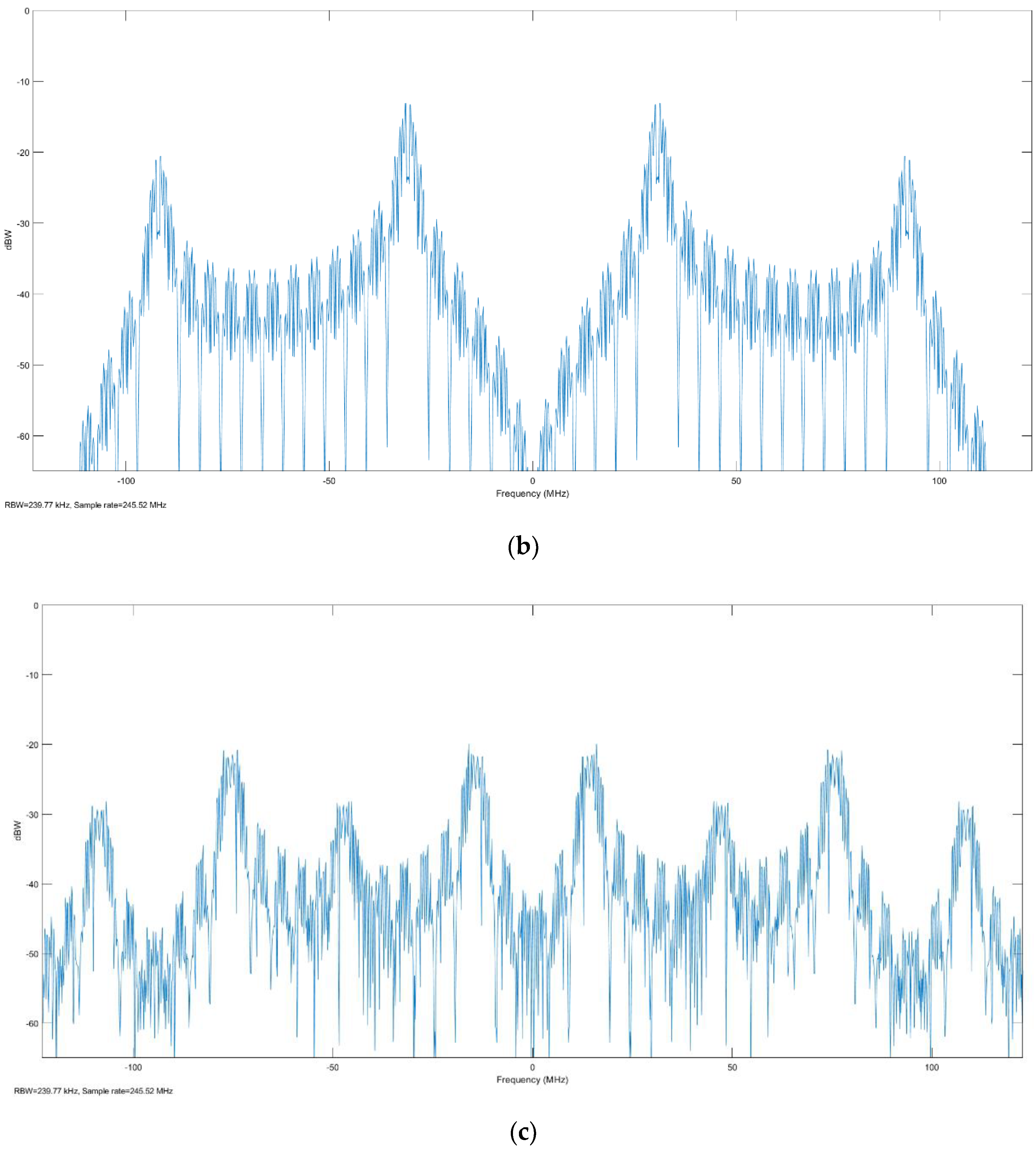
where is navigation data, represents the PN sequence and is the subcarrier sequence. For the BOC signal subcarrier, which can be chosen as sine phase, cosine phase, or non-zero dual polarity codes. Different subcarrier will influence the characteristics of the BOC signal. The BOCcos signal has the deepest null-forming in the center frequency than the other BOC signals. This property makes it easier to extract the 16APSK signal at the receiving end. Thus, we adopt BOCcos signal to transmit TT&C services. In a BOCcos signal, and can be expressed as (2) and (3):
Here, . is the width of the PN code. is the PN sequence.
To express the split spectrum characteristics of the BOC signal more intuitively [25], the power spectrum of the BOCcos signal is shown in (6):
This paper uses APSK to achieve data transmission services [24]. The baseband signal of APSK is expressed as (4):
where is the data and is the radius of the constellation diagram. is the signal points of a concentric circle. represents the initial phase.
The signal model of the integrated signal at baseband is shown as (5):
For a BOCcos signal, the parameters (m,n) of a BOCcos(m,n) signal are determined by the spectrum shape, the signal bandwidth and the bandwidth of the APSK signal. m is the multiple of the subcarrier frequency relative to the reference frequency , which means . n is the multiple of the spread spectrum code frequency relative to the reference frequency , and thus . Here, MHz [26].
To transmit voice, image and video, high-speed data transmission service often needs several Mbps or even hundreds of Mbps. Therefore, we set the bandwidth of data transmission as 10 MHz. Using 16APSK can achieve the transmission rate of hundreds of Mbps.
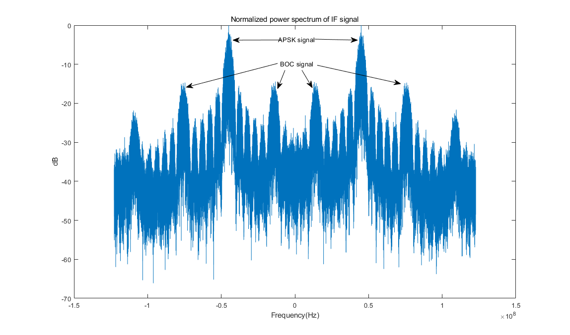
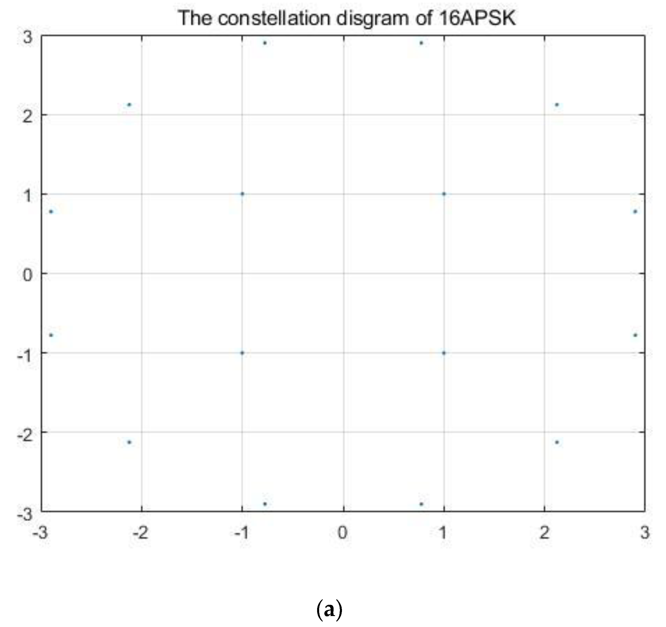
The BOCcos(15,2.5) signal is used to modulate the TT&C data in Galileo systems [25]. Besides, the bandwidth of the 16APSK signal should be less than the bandwidth of BOCcos’s null-forming. Thus, we use BOCcos(30,5) signal with the same properties as BOCcos(15,2.5) to transmit TT&C signal. The spread spectrum code frequency is 5.115 MHz, and the subcarrier frequency is 30.69 MHz. The 16APSK signal is 10 MHz, which is used for data transmission services. The constellation diagram of 16APSK is shown in Figure 1a. It has two concentric circles. The inner circle has four points, and the outer circle has twelve points [27,28].
The spectrum of the integrated signal at the intermediate frequency (IF) end is shown in Figure 1c.
2.2. The Concept of Modulation and Demodulation
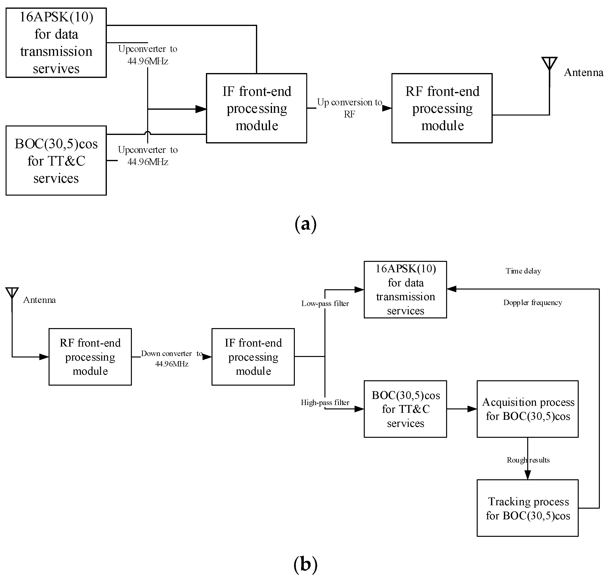
The design and implementation scheme of the BOCcos and 16APSK integrated signal system is shown in Figure 2. In the transmission link, the TT&C and data transmission service signals are generated by the BOCcos baseband signal and 16APSK baseband signal, respectively. Then, the two baseband signals are modulated to 44.96 MHz as a digital IF signal. After that, the system generates a 44.96 MHz analog IF signal through the digital-to-analog converter (DAC). In the radio frequency (RF) transmission channel, the signal is up to the RF, which is filtered and power-amplified. Then, it transmits the signal to the antenna. In addition, the data transmission signal power can be kept 10~30 dB higher than the TT&C signal. A more detailed analysis will be carried out in Section 5.2.
In the receiving link, when the signal is received by the antenna, the RF signal is downconverted to 44.96 MHz in the RF channel. Then, the digital IF signal is generated by the analog-to-digital converter (ADC). In addition, the BOCcos signal in the IF is acquired and tracked. The tracking results can eliminate the Doppler signal to ensure the demodulation of 16APSK.
3. The Receiving Method of the Integrated Signal in the TDD Mode
In this section, we will elaborate on the acquisition method used to obtain the TT&C results. However, considering that the tracking process of TT&C and the demodulation of 16APSK have no difference from the traditional method, and will not be discussed here. Finally, the motion compensation method in the TDD mode is shown.
3.1. The Acquisition Process of Integrated Signal
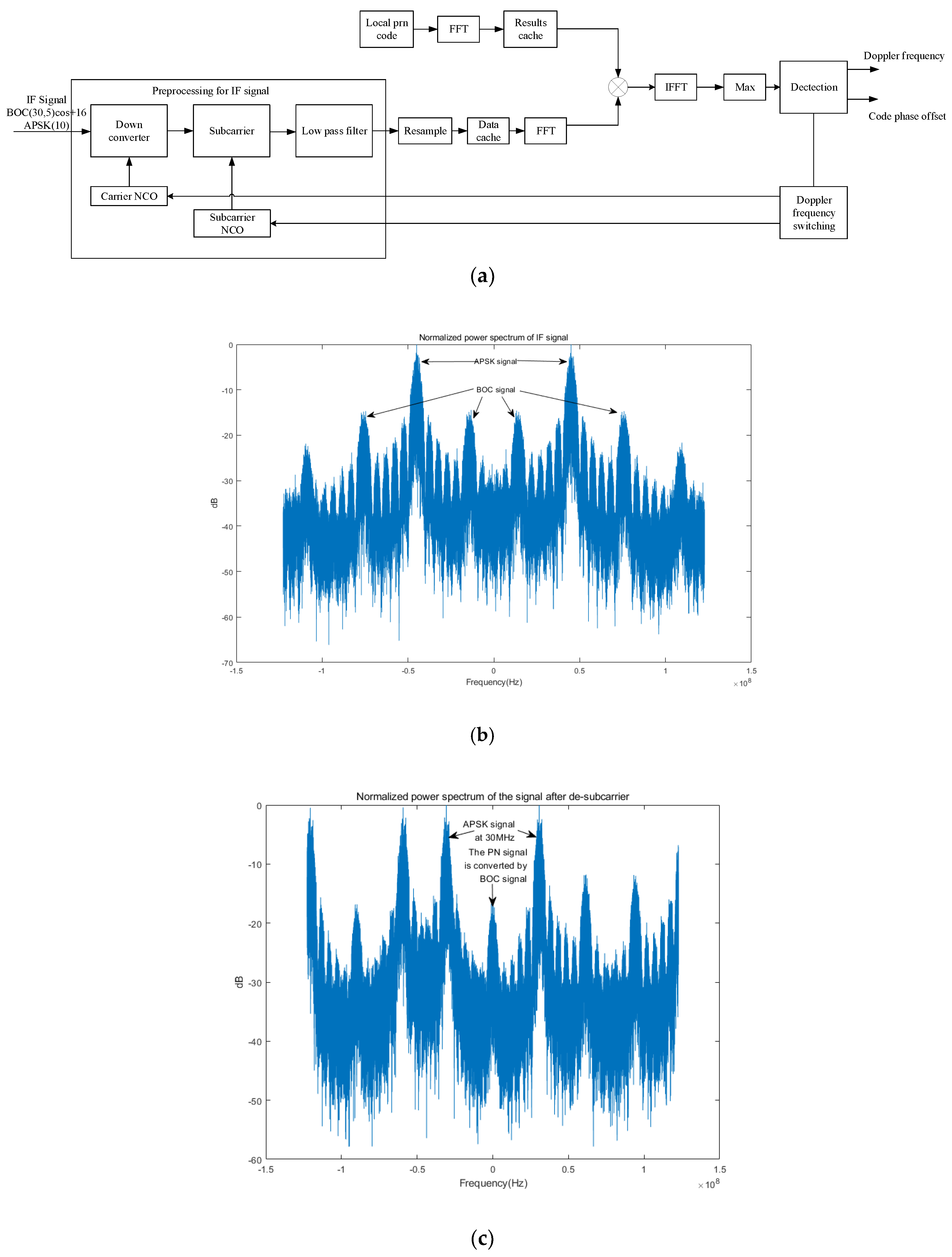
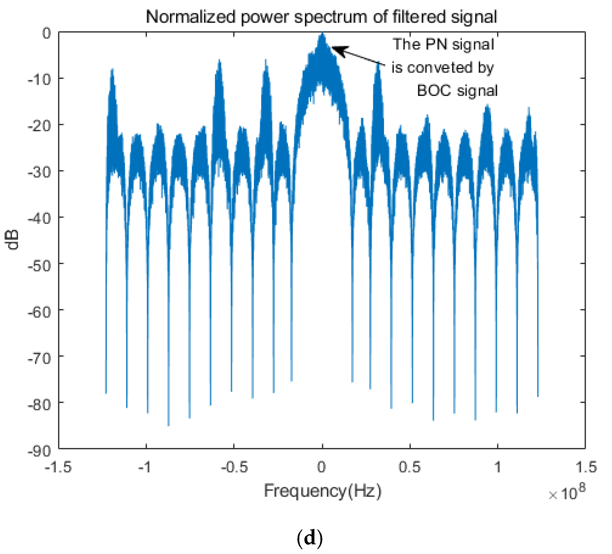
The acquisition process should give the rough code phase and Doppler frequency to the tracking process. Serial acquisition, parallel acquisition and parallel code phase searching are the three major methods for acquisition [29]. For BOC signals, due to the existence of subcarriers, the acquisition process needs to preprocess the signal. The acquisition methods of a pure BOCcos signal are shown in [30,31]. Ref. [32] gives a BPSK-like technique to acquire the BOC signal as two BPSK signals. However, the method will cause a 3dB signal loss. This paper restores the upper and lower sidebands to center frequency for processing, which will effectively avoid 3dB signal loss. The technique extracts the signals of the upper and lower sidebands of the BOC signal to the baseband and regards them as a C/A code for acquisition. And the acquisition method for C/A code is discussed in [33,34]. In this paper, the TT&C signals are extracted by using this technique, and there is no need for an independent filtering process of APSK signals
The preprocessing in the acquisition process is as follows.
Step 1. The control unit shifts the frequency of the carrier numerically controlled oscillator (NCO) by . In addition, the carrier NCO generates the in-phase and orthogonal carrier signals based on the frequency tuning word and mixes with the input signals.
Step 2. The subcarrier NCO generates the in-phase or orthogonal subcarrier signals and mixes them with the output signal of step 1.
Step 3. A low-pass filter is used to filter the signal and retain the baseband signal with a 10 MHz bandwidth.
The signal acquisition diagram is shown in Figure 3a.
Step 1 converts the IF signal to the baseband without filtering the high-frequency signals. The power spectrum of the processed signal is shown in Figure 3b. Step 2 restores the BOCcos signal to the spread spectrum signal. In addition, it will move the baseband APSK signal to the 30 MHz frequency. In this stage, the power spectrum of the signal changes to that shown in Figure 3c. Finally, step 3 can filter the spread spectrum signal in the baseband as Figure 3d.
After the preprocessing of the IF signal, the integrated signal can be compatible with the existing BOC signal processing system. In the paper, we adopt the fast Fourier transform (FFT) for the correlation to obtain rough estimates of the PN code and Doppler frequency.
3.2. Motion Compensation Method in TDD Mode
For multi-node spacecraft/aircraft networks, it is necessary to synchronize the time and eliminate the clock difference between different nodes. After that, the unified time standard can be adopted in the whole network [35]. In addition, the network does not need all nodes to use the global navigation satellite system (GNSS) or a ground station for timing and positioning, which greatly saves resources. In the ground system, clock synchronization technology mainly includes average time and double-difference or triple difference observation [36,37,38]. For intersatellite/aircraft links, the time synchronization and true distance can be measured via dual one-way ranging (DOWR) [36,39,40].
However, the DOWR method needs to measure the pseudo-range and velocity at the same time. In the TDD mode, the pseudo-range and velocity results obtained by the local measurements between different nodes are not obtained simultaneously. Here, we take nodes A and B as an example.
The pseudo-ranging and velocity results of node A can be expressed as and , and the results of node B can be expressed as and . and are the times when the results are obtained by local satellites or aircraft, respectively. Because the TDD mode cannot receive and transmit signals at the same time, the relation between and can be expressed as (7):
where is the switching period between the receiving and transmitting processes. denotes the error in the measurement process.
Via the following steps, the time of A and B measuring the pseudo-range and velocity can be corrected to the same time.
Step 1. Calculate the radial acceleration value between the spacecraft using the spacecraft orbit elements or the inertial navigation system (INS).
Step 2. According to (15), we can calculate the correct velocity using the radial acceleration value :
Step 3. The Doppler frequency can be calculated by (9).
Here, is the speed of light. is the radio frequency.
Step 4. is used to modify the pseudo-range value of the spacecraft via (10):
The second term on the right side of (11) is the pseudo-distance modifier.
Step 5. and are used to conduct DOWR. and are sent to the carrier tracking loop and code tracking loop to guarantee the stable tracking of the loop without receiving a signal.
The acceleration value of spacecraft can be obtained by spacecraft orbit elements or the INS. The former should consider oblate earth model, atmospheric resistance, lunar gravitation and sun gravitation perturbations, etc. And it uses J4 orbit propagator or high precision orbit perturbations (HPOP) to calculate the acceleration value. In [41], the error of orbit propagator is less than 10−3 m/s2. These elements can be uploaded in each satellite through the ground station at regular intervals. The latter method uses INS to obtain the acceleration value of the spacecraft. The messages are obtained autonomously by INS. The [42] shows the measurement value of INS is less than 104 m/s2. However, the acceleration direction measured by the two methods is different from the direction of the two spacecraft, and we need to project the acceleration vector to the direction between the spacecraft.
With the above extrapolation method, first, the times of the distance and velocity measurements by nodes A and B are synchronized. Thus, DOWR can be used to eliminate the distance error caused by the clock difference, and the integrated signal can provide high-precision measurements [43]. Second, the extrapolation ensures that the tracking loop remains locked during the TDD mode signal transmission period, which enables the loop to converge faster when receiving the signal input.
4. Performance Analysis of the TT&C Signal and Data Transmission Signal
In this section, we will investigate the performance of the integrated signal in terms of the acquisition time, tracking performance, bit error and measurement error. In addition, we will discuss the methods of reducing measurement error. Considering that data transmission services require more power than TT&C services, we set the power ratio of APSK and BOCcos to 10:1.
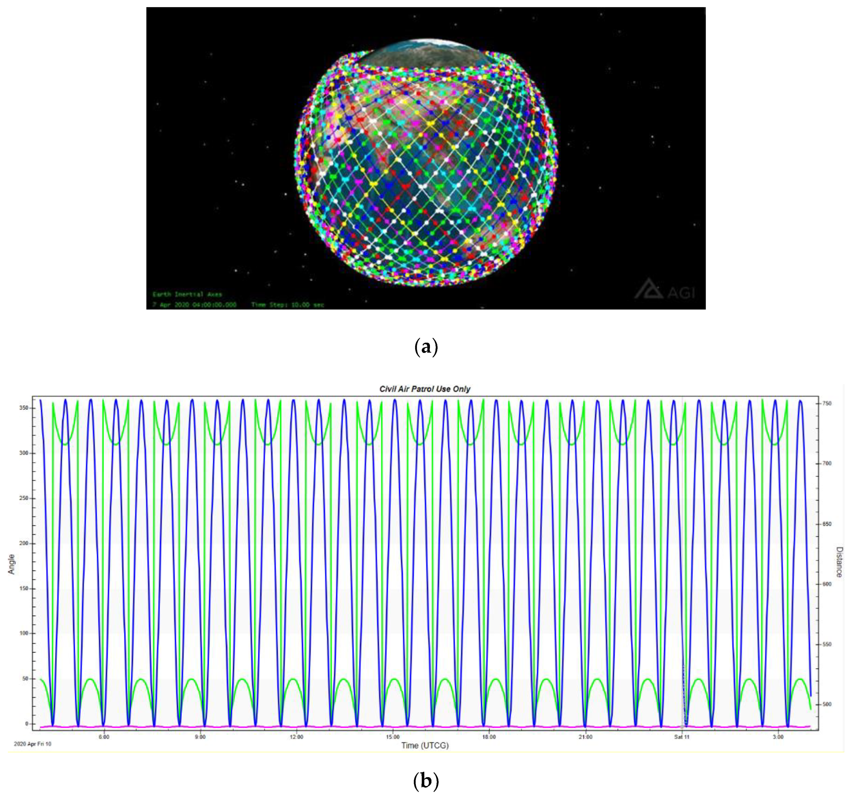
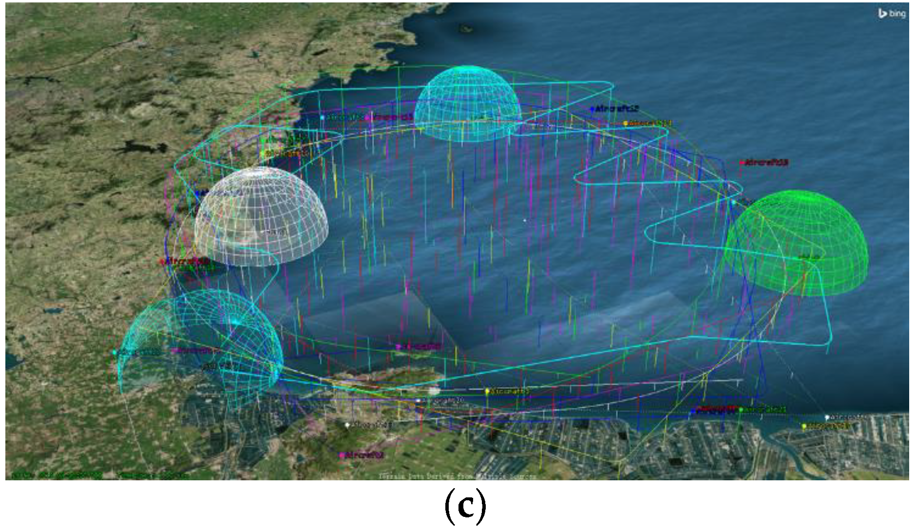
4.1. The Design of the Simulation Scenario
The design of the simulation scenario comes from the satellite toolkit (STK). For intersatellite links, we set the maximum distance and relative velocity between different nodes as 783 km and 602 km/h, respectively. From [31], The relationship between satellite’s transmitting signal power and receiving power is shown in (11).
Here, and is the received signal power and transmitted signal power. and is the antenna gain at receiver and transmitter. is the wavelength. represents the distance between the receiver and transmitter. is the atmospheric loss, which can be ignored for intersatellite links.
We set the satellite’s transmitting power is approximately 10 W, and the satellite’s antenna gain is less than 37.1 dB. The receiver antenna gain is 0. The Ka band is used for the intersatellite links [6,7,44]. The carrier-to-noise ratio (CNR) of the receiving end is higher than 55 dB-Hz. The trajectory in this process is obtained by the STK simulation, as shown in Figure 4a. The orbit parameters of satellites are shown in Table 1. Figure 4b) shows the distance between the visible satellites in adjacent orbital planes. The value changes following a cosine curve in the range of .
The inter-aircraft link scenario is shown in Figure 4c. The range between different nodes are less than 40 km, and the trajectory includes uniform motion, acceleration motion and S-curve motion. However, the carrier-to-noise ratio between UAVs is higher than the satellites, and the result is better than the satellite scene. Therefore, we only give the simulation results of the satellite scene. And the simulation results of aircraft scenes in some environments are given in Appendix A.
4.2. Acquisition Performance of the TT&C Signal
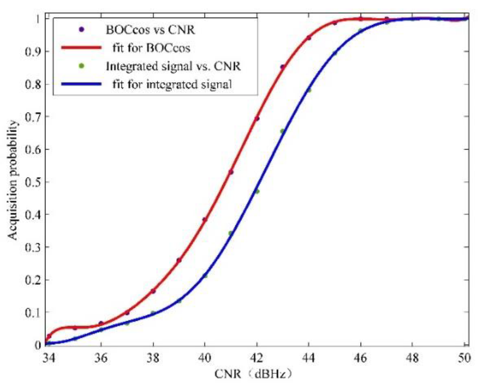
Because this paper adopts an integrated signal, the subpeak of the APSK signal will be interfered due to the existence of the BOC signal. In addition, the signal power of the data transmission signal is higher than that of the TT&C signal to ensure the bit error rate. This will further interfere with the acquisition of the BOCcos signal. In Figure 5, the acquisition probability of the CNR is given.
Obviously, the acquisition probability of the integrated signal is lower than that of the single BOCcos signal. The degradation of performance is approximately 2~3 dB. However, for intersatellite links and aircraft links, the CNR is higher than that of the satellite ground link. Therefore, the performance degradation is acceptable.
The clock cycle required for one acquisition process is shown in Table 2. Since the sampling frequency is set to 245.52 MHz, 409,105 sample points will be cached within 0.2 ms. After that, downsampling is realized 12 times, and the sample point number is reduced to 4093. Then, the data are zero-padded to 4096 points and sent to the FFT.
Considering other waiting times, the acquisition process in the FPGA set the margin to 200 clock cycles. The acquisition time . For intersatellite links, the Doppler frequency search range is generally set to . Therefore, if 500 Hz is used as the step, the time for searching all frequency points is 11.4 ms. However, due to the existence of missed detections, the acquisition time will be longer. Due to the tong detector is used to reduce the false probability, the resident time will increase at each frequency [33,43]. Each frequency will be searched eight times at low SNR and three times at high SNR. Take six times as acquisition time, which is equal to 66.57 ms. For the TDD mode, the hardware can search the code phase and Doppler frequency when in the TDD mode receiving stage. Thus, the duration of the TDD mode receiving and transmitting stage should not less than acquisition time.
4.3. Tracking Performance for the TT&C Signal
In the tracking process, the pseudo-range and Doppler frequency are the main measurements [42]. The ranging error refers to the code loop tracking error, and its main sources are thermal noise error and dynamic stress error. The latter is eliminated by carrier-assisted PN code technology, and the thermal noise error can be calculated as (12):
Here, represents the width of a chip, which is 58.6 m for BOCcos(30,5). is the bandwidth of the code tracking loop. CNR is the carrier-to-noise ratio of the TT&C receiving signal. represents the chip interval of the delay locked loop (DLL). represents the integration time [45].
For the Doppler frequency, the thermal noise error of the three-order phase locked loop (PLL) is calculated as (13).
The Doppler frequency can be calculated as (14).
Considering the convergence speed and tracking error of the DLL and PLL, we set and Hz. In this situation, the ranging error is 0.0755 m when CNR = 55 dBHz, and the Doppler frequency measurement error is 0.0127 Hz. If it is necessary to improve the measurement accuracy, it is very effective to average the measurement results, increase the or improve the CNR.
In Section 3.2, the extrapolation method is used in the transmission stage of the TDD mode, which will cause errors. The acceleration measurement error and velocity measurement error are assumed to be and , respectively. Therefore, the velocity measurement error caused by the acceleration error is , and the ranging error is as shown in (15).
The correction error shows that the shorter the switching period is, the smaller the extrapolation error in the TDD process. For example, if , and , the pseudo-range correction error by extrapolation is less than 0.10005 m. If , the correction error is less than 1.005 m. Considering the bit transitions, the relationship between the correction errors and whether the tracking process requires recapturing is shown in Table 3. The threshold is related to the parameter selection of the frequency-locked loop and the DLL.
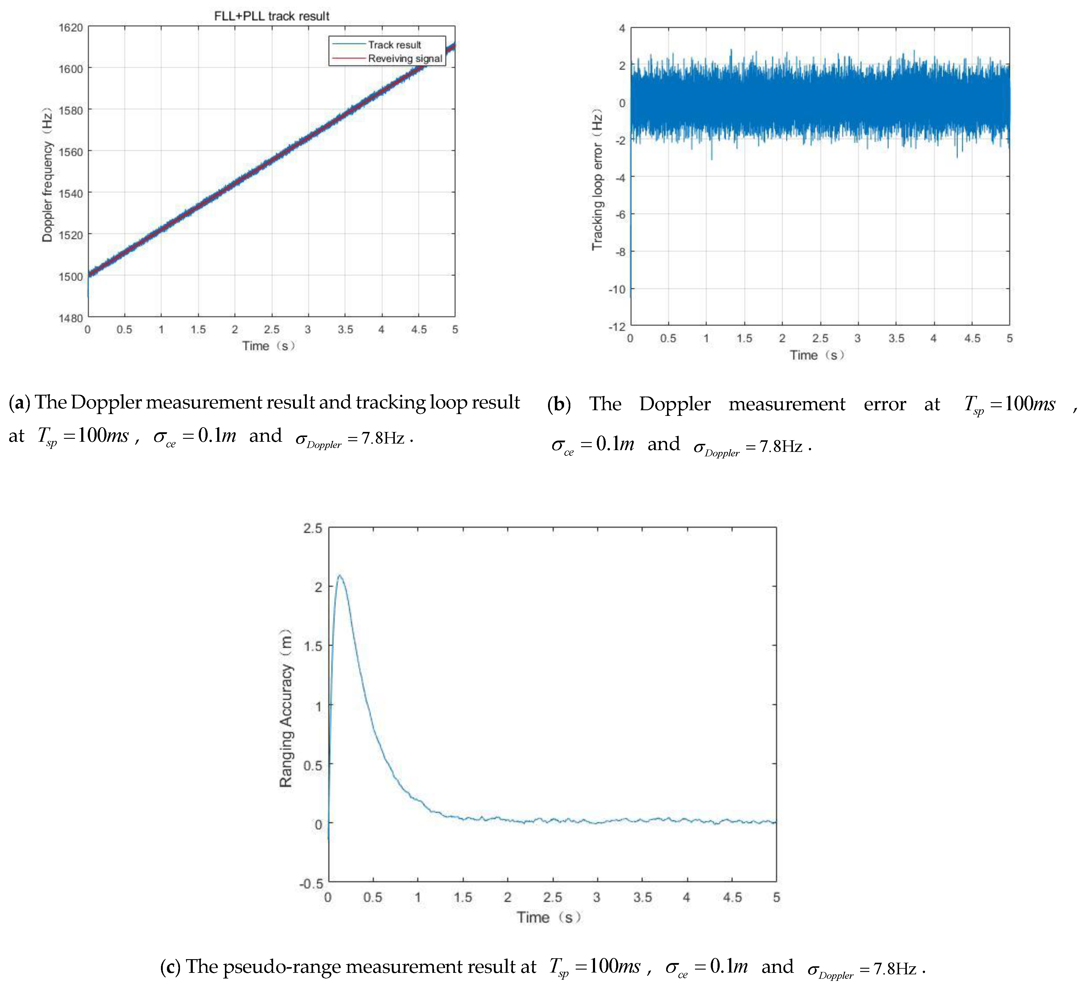
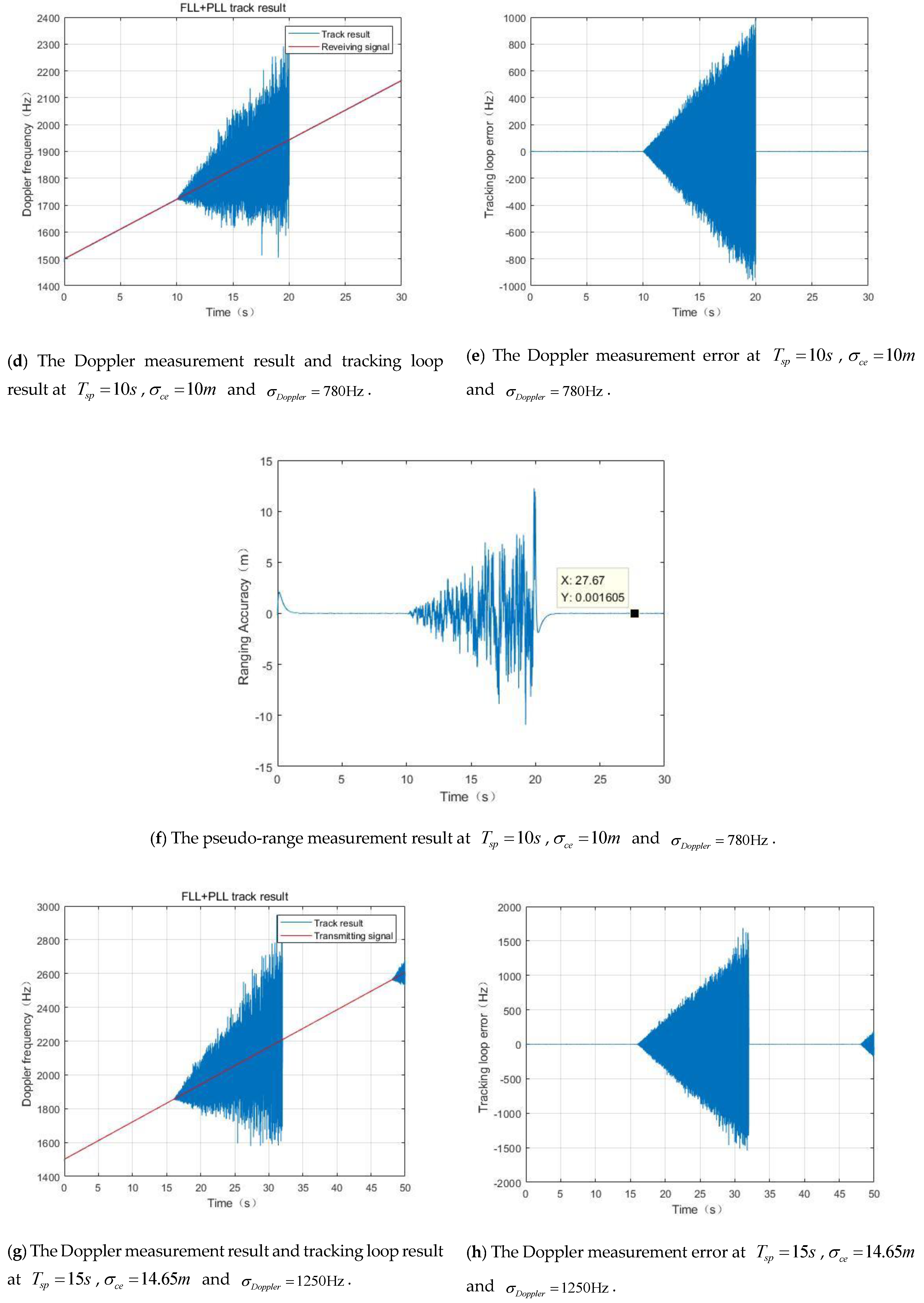
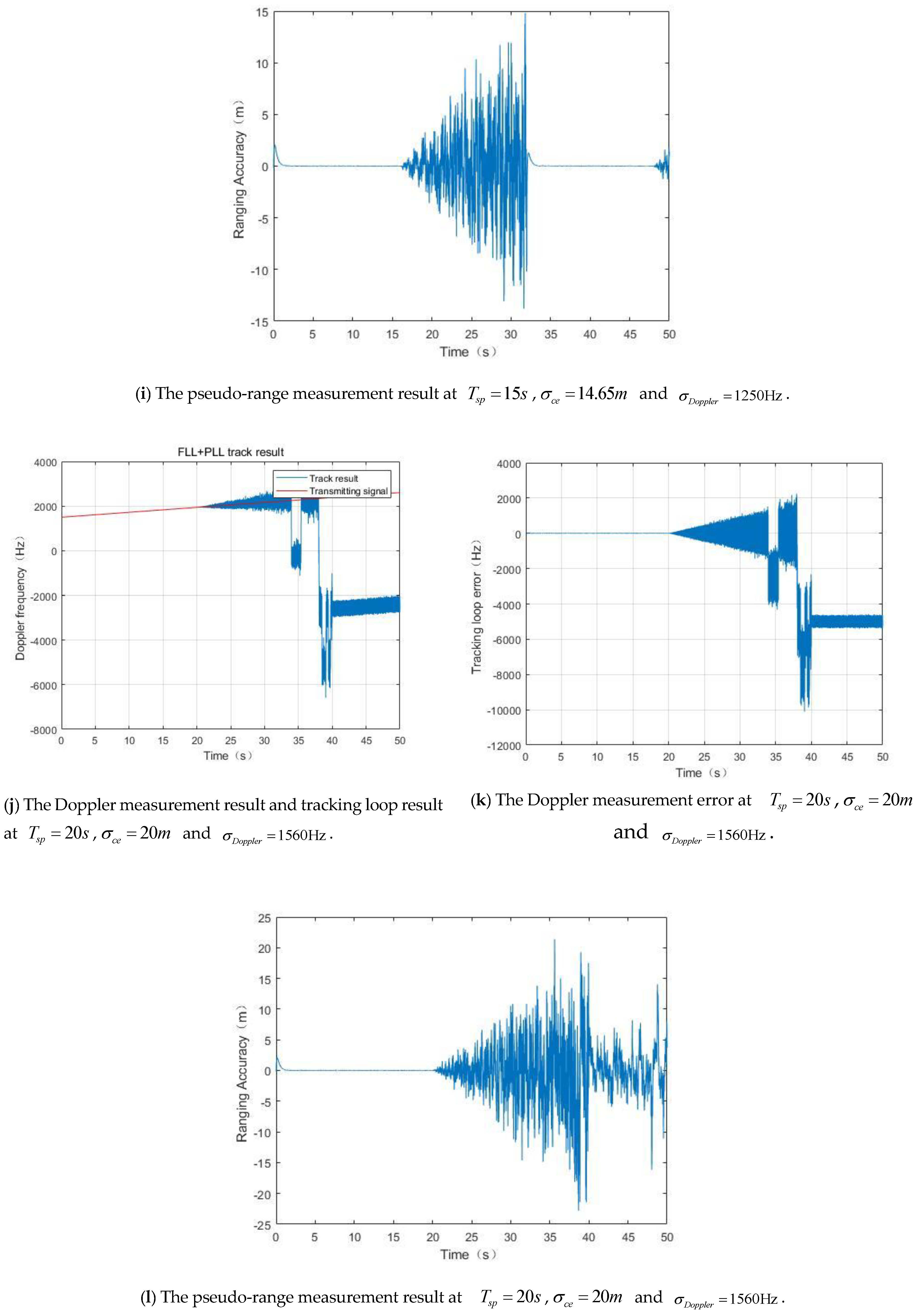
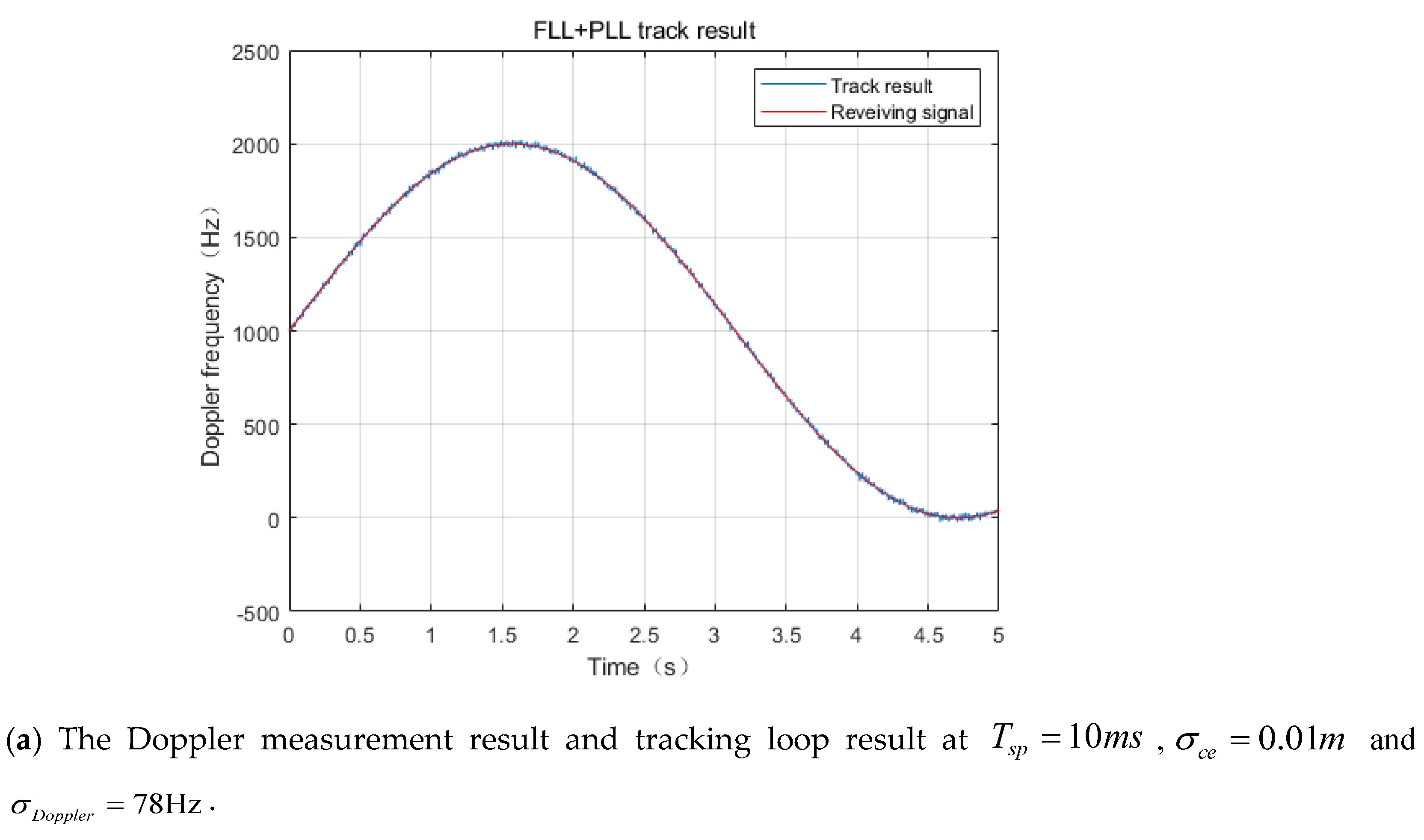
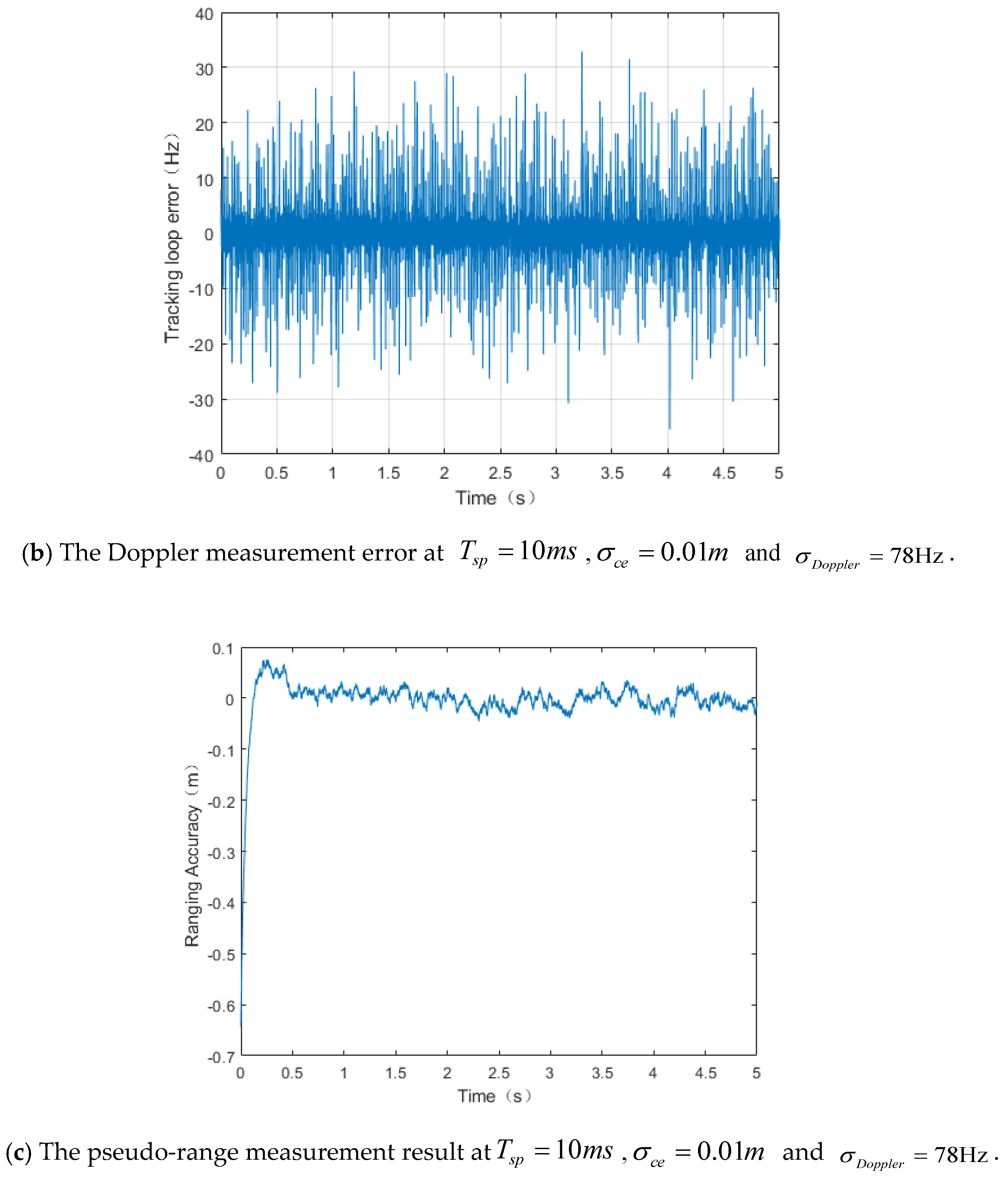
The Doppler and pseudo-range measurements at different switching periods are shown in Figure 6.
Excessive extrapolation errors of the Doppler frequency and ranging during the TDD switching period will cause loop unlocking and reacquisition. The simulation shows that if the Doppler extrapolation error exceeds and the distance extrapolation error exceeds at the receiving and transmitting switch time, the tracking loop will unlock.
5. Discussion
Due to the modulation of two kinds of signals at the same frequency point, the subpeaks of the two signals have an impact on the TT&C and data transmission performance of each other. This section is conducting simulation research to study the deterioration of the performance.
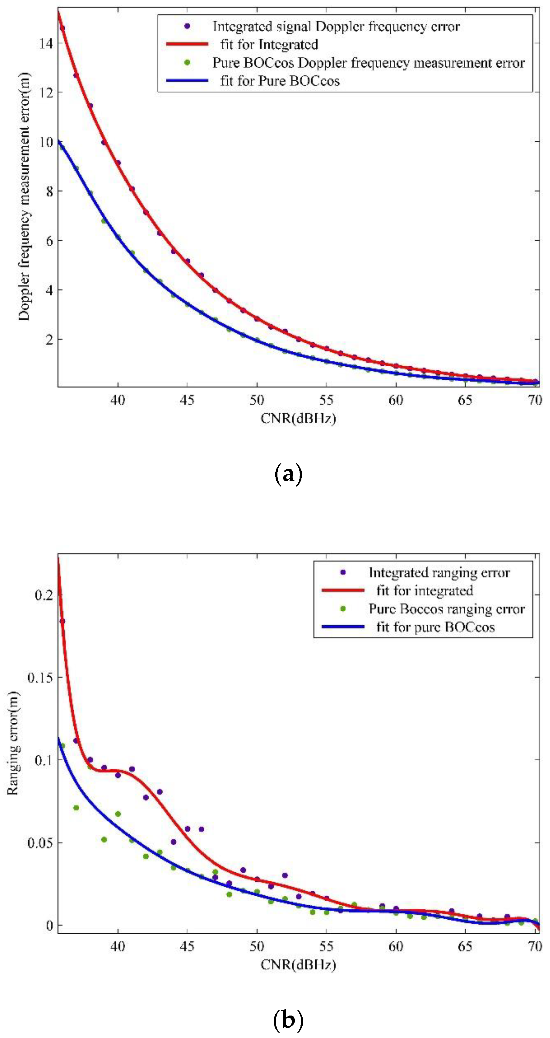
5.1. Ranging and Doppler Measurement Performance for Integrated Signals
When the simulation parameters are , and , compared with the pure BOC signal, the measurement accuracy is reduced mainly due to the interference of the APSK’s subpeak, which will reduce the CNR of the TT&C signal. The degree of the decrease in the signal is the same as that during the acquisition process. The measurement results are shown in Figure 7.
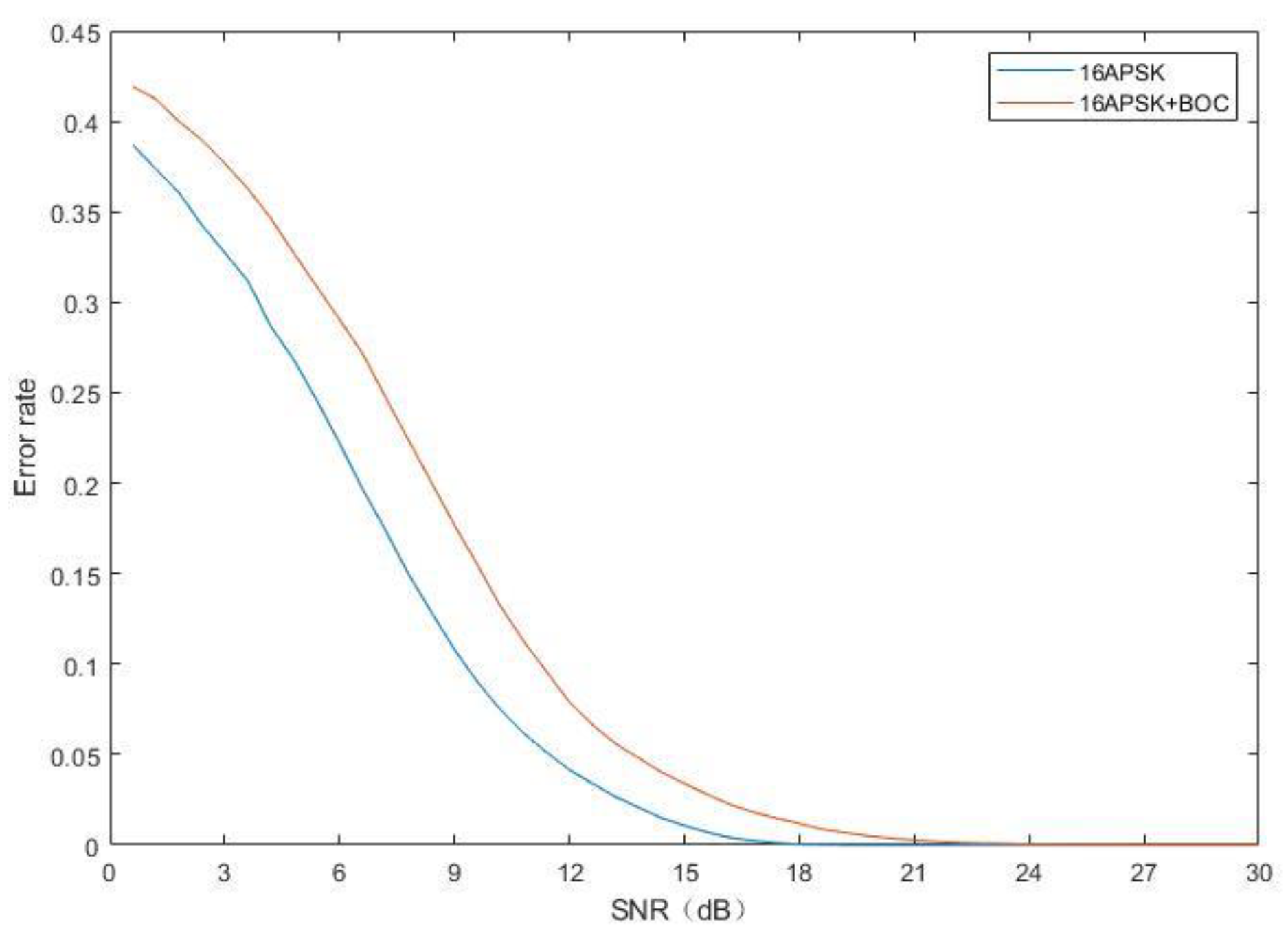
5.2. Bit Error Rate (BER) for Integrated Signals
It is necessary to obtain the data transmission signal from the integrated signal via filtering. In the separation process, the filter will reduce the CNR of the signal and eventually increase the BER.
The BER of the integrated signal and pure signal are shown in Figure 8. If the integrated signal needs to achieve the same BER, the CNR of the integrated signal will be 4~5 dB higher than that of a single signal.
For BOC signal, the BER will be less than 1e-4 when success is acquired. Therefore, Figure 5 and Figure 8 show the BER of TT&C signal is higher than the data transmission signal at the same CNR. Thus, the data transmission signal power can be kept 10~30 dB higher than the TT&C signal. If the power is higher than this level, the subpeak of the data transmission signal will interfere with the measurement of the BOC signal. If it is lower than 10 dB, the power of the BOC signal should keep a high level, which is not necessary for TT&C.
5.3. Summary of Error Suppression Methods
According to the results of the software simulation, the measures used to improve the measurement accuracy are as follows:
- (1)
- Improve the PN code rate, which will reduce .
- (2)
- Increase the length of the PN code. The method can increase the integration period.
- (3)
- Increase the integration period.
- (4)
- Reduce the bandwidth of the loop. However, the stability of the loop will be weakened, so the error and SNR in the extrapolation process should be considered comprehensively.
- (5)
- Reduce the switching period of the TDD mode. This method can effectively reduce the extrapolation errors.
These methods can be adjusted in baseband signal processing.
In addition, during the TT&C process between satellites, there will be measurement errors caused by the ionosphere. However, the error can be eliminated by two or three frequency links. Taking the S/X dual frequency measurement as an example, the effect of the residual ionospheric high-order term on the group delay will be less than 1 mm. Moreover, when the flight orbits of the satellite are at the same altitude, the ionospheric change rate will be smaller than when the flight orbits are at different altitudes.
6. Conclusions
In this paper, for a network with a large number of satellites or aircrafts, we propose a BOCcos and 16APSK integrated signal in the TDD mode. The signal can achieve TT&C and data transmission at the same frequency, which greatly improves spectrum utilization. The equipment can be easily integrated and miniaturized. In addition, this paper improves the TDD mode, which is commonly used in mobile communication systems to increase spectrum utilization, so that it can be applied to the TT&C of intersatellite links. The combination of the two can significantly reduce the costs of intersatellite links and inter-aircraft links. The acquisition and tracking process of BOCcos + 16APSK is analyzed and simulated. Although the performance is reduced by approximately 2~3 dB, the acquisition and tracking process is fully applicable to high-CNR environments such as intersatellite links or inter aircraft links. In addition, to solve the problem in which the TDD mode is not received and received simultaneously, this paper uses an extrapolation method to cause the loop to keep tracking continuously without reacquisition, which reduces the constraint of the acquisition time on the TDD switching period. The ranging extrapolation error threshold is less than , and the frequency extrapolation error threshold is less than . Finally, the ranging accuracy of the system is less than 9 cm. In the future, we will improve the BOC signal acquisition method in this scenario. In this paper, BPSK-like is used to signal acquisition. Although the method is simple, the advantage of narrow correlation peak of BOC signal is abandoned.
Author Contributions
Conceptualization, X.L. and W.W.; methodology, Y.Y.; software, L.Y.; validation, L.X. and X.L.; formal analysis, L.X.; investigation, Y.Y.; resources, W.W.; data curation, L.X.; writing—original draft preparation, L.X.; writing—review and editing, L.X. and X.L. visualization, Y.Y.; supervision, Y.Y.; project administration, W.W. All authors have read and agreed to the published version of the manuscript.
Funding
This research was funded by Technology and Industry for National Defense, grant number No. 060301 and No.B0110.
Conflicts of Interest
The authors declare no conflict of interest.
Appendix A
We give the simulation results at aircraft scenario in Figure A1. And we get the same conclusion as the satellite scene.
Figure A1.
The measurement results at aircraft scenario, CNR = 60 dBHz.


References
- Crisan, A.-M.; Martian, A.; Cacoveanu, R.; Coltuc, D. Evaluation of synchronization techniques for inter-satellite links. In Proceedings of the 2016 International Conference on Communications (COMM), Bucharest, Romania, 9–10 June 2016; pp. 463–468. [Google Scholar]
- Wu, W.R.; Dong, G.L.; Li, H.T. Engineering and Technology of Deep Space TT&C System; China Science Publishing & Media Ltd.: Beijing, China, 2013; pp. 143–194. [Google Scholar]
- Wu, W.; Li, H.; Li, Z.; Wang, G.; Tang, Y. Status and prospect of China’s deep space TT&C network. Sci. Sin. Inf. 2020, 50, 87–127. [Google Scholar] [CrossRef]
- Veres, P.M.; Gabányi, K.É.; Frey, S. Very Long Baseline Interferometry Observations of the Proposed Radio Counterpart of an EGRET Source. Symmetry 2020, 12, 1516. [Google Scholar] [CrossRef]
- Kinman, P. Doppler tracking of planetary spacecraft. IEEE Trans. Microw. Theor. Tech. 1992, 40, 1199–1204. [Google Scholar] [CrossRef]
- Del Portillo, I.; Cameron, B.G.; Crawley, E.F. A technical comparison of three low earth orbit satellite constellation systems to provide global broadband. Acta Astronaut. 2019, 159, 123–135. [Google Scholar] [CrossRef]
- Foreman, V.L.; Siddiqi, A.; De Weck, O.L. Large Satellite Constellation Orbital Debris Impacts: Case Studies of OneWeb and SpaceX Proposals. AIAA SPACE Astronaut. Forum Expos. 2017, 5200. [Google Scholar] [CrossRef]
- Li, Y.; Wang, Z.; Tan, W. The frequency spectrum management for aerospace TT&C system. In Proceedings of the 2013 5th IEEE International Symposium on Microwave, Antenna, Propagation and EMC Technologies for Wireless Communications, Chengdu, China, 29–31 October 2013; pp. 595–600. [Google Scholar] [CrossRef]
- Gu, X.; Bai, J.; Zhang, C.; Gao, H. Study on TT&C resources scheduling technique based on inter-satellite link. Acta Astronaut. 2014, 104, 26–32. [Google Scholar] [CrossRef]
- Tianjiao, Z.; Jing, L.; Zexi, L.; Ming, X. An Algorithm Research of Ground-Space Integrated Scheduling TT&C Resources of Orbit Determination of GNSS Constellation. In Proceedings of the 2013 Fourth International Conference on Intelligent Systems Design and Engineering Applications, Zhangjiajie, China, 6–7 November 2013; pp. 69–73. [Google Scholar]
- Yan, L. The Design and Implement of TT&C and Data Transmission Integrated System of Satellite; Nanjing University of Science & Technology: Nanjing, China, 2018. [Google Scholar]
- Abdullah, A.; Elnoubi, S.; Banna, M.; Nasr, M. Implementation of multi-user detection for ds-cdma communications. In Proceedings of the Twenty-Second National Radio Science Conference, NRSC 2005, Cairo, Egypt, 15–17 March 2005; pp. 403–410. [Google Scholar]
- Jovic, B.; Unsworth, C.; Sandhu, G.; Berber, S.M. A robust sequence synchronization unit for multi-user DS-CDMA chaos-based communication systems. Signal Process. 2007, 87, 1692–1708. [Google Scholar] [CrossRef]
- Nie, S.J.; He, B.Z.; Wang, H.Z.; Qin, Y.F. Design of integration channel of ranging and data transmission. Mod. Electron. Tech. 2013, 36, 57–62. [Google Scholar]
- Chen, S.; Sun, S.; Wang, Y.; Xiao, G.; Tamrakar, R. A comprehensive survey of TDD-based mobile communication systems from TD-SCDMA 3G to TD-LTE(A) 4G and 5G directions. China Commun. 2015, 12, 40–60. [Google Scholar] [CrossRef]
- Aslam, M.; Jiao, X.; Liu, W.; Moerman, I. An Approach to Achieve Zero Turnaround Time in TDD Operation on SDR Front-End. IEEE Access 2018, 6, 75461–75470. [Google Scholar] [CrossRef]
- Betz, J.W. Binary offset carrier modulation for radio navigation. Navigation 2001, 48, 227–246. [Google Scholar] [CrossRef]
- Wang, H.-Y.; Juang, J.-C. Retrieval of Ocean Surface Wind Speed Using Reflected BPSK/BOC Signals. Remote Sens. 2020, 12, 2698. [Google Scholar] [CrossRef]
- Pickholtz, R.; Schilling, D.; Milstein, L. Theory of Spread-Spectrum Communications—A Tutorial. IEEE Trans. Commun. 1982, 30, 855–884. [Google Scholar] [CrossRef] [Green Version]
- Rong, L.; Yingfeng, X. A multi-aircraft cooperative UAV observe and control system. J. Terahertz Sci. Electron. Inf. Technol. 2016, 14, 706–711. [Google Scholar]
- Liuqing, Y.; Qiangui, X. A UAV TT&C System for One Station Controlling Several Vehicles. Electron. Optics Control 2013, 20, 6–15. [Google Scholar]
- Guo, S.; Huang, G.; Liu, B.; Gao, Y. Research of MAPSK modulation based on the nonlinear satellite channel. In Proceedings of the 2010 3rd IEEE International Conference on Broadband Network and Multimedia Technology (IC-BNMT), Beijing, China, 26–28 October 2010; pp. 1197–1201. [Google Scholar]
- Manqian, Z.; Jian, L.; Bo, Y.; Guangnan, Z. Research on high order modulation for satellite communications. Electronic. Des. Eng. 2014, 22, 114–117. [Google Scholar]
- Zhang, J.; Zhu, L.; Guo, Y.; Gou, X. A new method of demodulation for 16APSK/32APSK. In Proceedings of the Proceedings of 2012 5th Global Symposium on Millimeter-Waves, Harbin, China, 27–30 May 2012; pp. 477–481. [Google Scholar]
- Saxena, T.; Jadon, J.S. Spectral analysis of Sine and Cosine BOC modulated signals. In Proceedings of the 2014 International Conference on Signal Processing and Integrated Networks (SPIN), Noida, India, 20–21 February 2014; pp. 734–738. [Google Scholar]
- Lohan, E.S.; Lakhzouri, A.; Renfors, M. Binary-offset-carrier modulation techniques with applications in satellite navigation systems. Wirel. Commun. Mob. Comput. 2007, 7, 767–779. [Google Scholar] [CrossRef]
- Machida, M.; Handa, S.; Oshita, S. Theoretical analysis of symbol error rates of (4,12) circular-signal-set constellation for some detection schemes. Electron. Commun. Jpn. Part I Commun. 2000, 83, 19–28. [Google Scholar] [CrossRef]
- Bhuiyan, M.Z.H.; Söderholm, S.; Thombre, S.; Ruotsalainen, L.; Kuusniemi, H. Implementation of a Software-Defined BeiDou Receiver. In Proceedings of the China Satellite Navigation Conference (CSNC) 2014 Proceedings, Nanjing, China, 21–23 May 2014; Springer: Berlin, Germany, 2014; Volume 303, pp. 751–762. [Google Scholar]
- Meng, S.; Yang, W.; Lu, W.; Liu, J.; Yu, J. Code tracking performance of DS/FH spread spectrum signal for TT&C. In Proceedings of the 2010 2nd IEEE International Conference on Information Management and Engineering, Chengdu, China, 16–18 April 2010; pp. 491–495. [Google Scholar]
- Yang, W.; Meng, S.; Wang, J.; Liu, J. Acquisition performance analysis of a synchronization scheme of DS/FH hybrid spread spectrum signals for TT&C. In Proceedings of the IEEE 2011 10th International Conference on Electronic Measurement & Instruments, Beijing, China, 16–19 August 2009; pp. 4–395. [Google Scholar]
- Wen, L.; Yue, X.; Zhongliang, D.; Jichao, J.; Lu, Y. Correlation combination ambiguity removing technology for acquisition of sine-phased BOC(kn,n) signals. China Commun. 2015, 12, 86–96. [Google Scholar] [CrossRef]
- Burian, A.; Lohan, E.S.; Renfors, M. BPSK-like Methods for Hybrid-Search Acquisition of Galileo Signals. In Proceedings of the 2006 IEEE International Conference on Communications, Istanbul, Turkey, 11–15 June 2006; Volume 11, pp. 5211–5216. [Google Scholar]
- Xie, G. Principles of GPS and Receiver Design; Publishing House of Electronics Industry: Beijing, China, 2009; pp. 349–393. [Google Scholar]
- Benedetto, F.; Giunta, G.; Lohan, E.S.; Renfors, M. A Fast Unambiguous Acquisition Algorithm for BOC-Modulated Signals. IEEE Trans. Veh. Technol. 2012, 62, 1350–1355. [Google Scholar] [CrossRef]
- Wang, C.; Zhou, M. Novel Approach to Intersatellite Distance Measurement with High Accuracy. J. Guid. Control. Dyn. 2015, 38, 944–949. [Google Scholar] [CrossRef]
- Kuang, K.; Zhang, S.; Li, J. Real-time GPS satellite orbit and clock estimation based on OpenMP. Adv. Space Res. 2019, 63, 2378–2386. [Google Scholar] [CrossRef]
- Maciuk, K.; Lewińska, P. High-Rate Monitoring of Satellite Clocks Using Two Methods of Averaging Time. Remote Sens. 2019, 11, 2754. [Google Scholar] [CrossRef] [Green Version]
- El-Mowafy, A. Impact of predicting real-time clock corrections during their outages on precise point positioning. Surv. Rev. 2017, 51, 183–192. [Google Scholar] [CrossRef]
- Liu, G.; Guo, F.; Wang, J.; Du, M.; Qu, L. Triple-Frequency GPS Un-Differenced and Uncombined PPP Ambiguity Resolution Using Observable-Specific Satellite Signal Biases. Remote Sens. 2020, 12, 2310. [Google Scholar] [CrossRef]
- Jia, X.; Zeng, T.; Ruan, R.; Mao, Y.; Xiao, G. Atomic Clock Performance Assessment of BeiDou-3 Basic System with the Noise Analysis of Orbit Determination and Time Synchronization. Remote Sens. 2019, 11, 2895. [Google Scholar] [CrossRef] [Green Version]
- Xiangqiang, M. Research and Application of Satellite Orbit Prediction Method Based on osculationg Kepler Element; University of Chinese Academy of Sciences: Beijing, China, 2017. [Google Scholar]
- Wenbing, W.; Rongfang, L. A new method of orbit prediction for LEO satellites using empirical accelerations. Chin. J. Space Sci. 2015, 35, 715–720. [Google Scholar]
- Liu, X.; Wang, D.; Zhong, X.; Meng, Y. Research on the Inversion Method of USO Frequency Stability Joining GNSS and Inter-satellite Distance Measurement. In Proceedings of the China Satellite Navigation Conference (CSNC) 2016 Proceedings, Changsha, China, 18–20 May 2016; Springer: Berlin, Germany, 2016; Volume 390, pp. 3–13. [Google Scholar]
- Hao, F.; Yu, B.; Gan, X.; Jia, R.; Zhang, H.; Huang, L.; Wang, B. Unambiguous Acquisition/Tracking Technique Based on Sub-Correlation Functions for GNSS Sine-BOC Signals. Sensors 2020, 20, 485. [Google Scholar] [CrossRef] [Green Version]
- Kaplan, E. Understanding GPS:Principles and Applications, 2nd ed.; Artech House: Boston, MA, USA, 2006; pp. 153–240. [Google Scholar]
- Parkinson, B.W.; Enge, P.; Axelrad, P.; Spilker, J.J., Jr. Global Positioning System: Theory and Applications; American Institute of Aeronautics and Astronautics (AIAA): Washington, DC, USA, 1996; pp. 409–433. [Google Scholar]
- Divsalar, D.; Net, M.S.; Cheung, K.-M. Acquisition and tracking for communications between Lunar South Pole and Earth. In Proceedings of the 2019 IEEE Aerospace Conference, Big Sky, MT, USA, 2–9 March 2019; pp. 1–14. [Google Scholar]
Figure 1.
The characteristics of the BOCcos(30,5) and 16APSK integrated signal. (a) The constellation of 16APSK (b) The spectrum of BOCcos(30,5) at the baseband (c) The spectrum of BOC(30,5)cos and 16APSK at the IF.
Figure 1.
The characteristics of the BOCcos(30,5) and 16APSK integrated signal. (a) The constellation of 16APSK (b) The spectrum of BOCcos(30,5) at the baseband (c) The spectrum of BOC(30,5)cos and 16APSK at the IF.


Figure 2.
The BOC(30,5)cos and 16APSK integrated signal system. (a) Transmission link structure (b) Receiving link structure.
Figure 2.
The BOC(30,5)cos and 16APSK integrated signal system. (a) Transmission link structure (b) Receiving link structure.

Figure 3.
Design of TT&C signal processing. (a) Signal acquisition (b) Normalized power spectrum of the IF signal (c) Normalized power spectrum of the signal after the desubcarrier (d) Normalized power spectrum of the signal after the low-pass filter.
Figure 3.
Design of TT&C signal processing. (a) Signal acquisition (b) Normalized power spectrum of the IF signal (c) Normalized power spectrum of the signal after the desubcarrier (d) Normalized power spectrum of the signal after the low-pass filter.


Figure 4.
Simulation scenario design. (a) Satellite orbit. (b) The distance between visible satellites (24 h). (c) Aircraft scenario.
Figure 4.
Simulation scenario design. (a) Satellite orbit. (b) The distance between visible satellites (24 h). (c) Aircraft scenario.


Figure 5.
The acquisition probabilities of an integrated signal and a BOC signal.

Figure 6.
The measurement results when CNR = 60 dBHz.


Figure 7.
The ranging and doppler measurement performance of an integrated signal and pure signal: (a) Doppler frequency measurement results of integrated signal and pure BOCcos signal; (b) Ranging results of integrated signal and pure BOCcos signal.
Figure 7.
The ranging and doppler measurement performance of an integrated signal and pure signal: (a) Doppler frequency measurement results of integrated signal and pure BOCcos signal; (b) Ranging results of integrated signal and pure BOCcos signal.

Figure 8.
The data transmission error rate of an integrated signal and pure signal.


Table 1.
The orbit parameters of satellites.
| Satellite number | 3364 |
| Orbit inclination | |
| Orbit altitude | 508 km |
| Orbital plane | 58 |
| The satellites in each plane | 58 |
| Number | 3364 |
Table 2.
Required clock cycles for once acquisition process.
| Process | Clock Cycle |
|---|---|
| Downsampling | 4096 |
| FFT of the downsampled signal | 409612 |
| Complex multiplication between the local PN code and downsampled signal | 4096 |
| IFFT of the multiplication result | 409612 |
| Maximum searches | 4096 |
| Threshold calculation | 1280 |
| Total | 111,872 |
Table 3.
The relationship between the correction errors and whether the tracking process requires reacquisition.
Table 3.
The relationship between the correction errors and whether the tracking process requires reacquisition.
| Threshold | Whether the Tracking Process Requires Reacquisition |
|---|---|
| And | No |
| Or | Yes |
© 2020 by the authors. Licensee MDPI, Basel, Switzerland. This article is an open access article distributed under the terms and conditions of the Creative Commons Attribution (CC BY) license (http://creativecommons.org/licenses/by/4.0/).
Share and Cite
MDPI and ACS Style
Xue, L.; Li, X.; Wu, W.; Yang, Y. Design of Tracking, Telemetry, Command (TT&C) and Data Transmission Integrated Signal in TDD Mode. Remote Sens. 2020, 12, 3340. https://0-doi-org.brum.beds.ac.uk/10.3390/rs12203340
AMA Style
Xue L, Li X, Wu W, Yang Y. Design of Tracking, Telemetry, Command (TT&C) and Data Transmission Integrated Signal in TDD Mode. Remote Sensing. 2020; 12(20):3340. https://0-doi-org.brum.beds.ac.uk/10.3390/rs12203340
Chicago/Turabian StyleXue, Linshan, Xue Li, Weiren Wu, and Yikang Yang. 2020. "Design of Tracking, Telemetry, Command (TT&C) and Data Transmission Integrated Signal in TDD Mode" Remote Sensing 12, no. 20: 3340. https://0-doi-org.brum.beds.ac.uk/10.3390/rs12203340
Note that from the first issue of 2016, this journal uses article numbers instead of page numbers. See further details here.