Parametric Design of a Microwave Radiometer for Land Surface Temperature Retrieval from Moon-Based Earth Observation Platform


1
Key Laboratory of Digital Earth Science, Aerospace Information Research Institute, Chinese Academy of Sciences, Beijing 100094, China
2
Institute of Remote Sensing and Digital Earth, University of Chinese Academy of Sciences, Beijing 100049, China
*
Author to whom correspondence should be addressed.
Remote Sens. 2020, 12(24), 4110; https://0-doi-org.brum.beds.ac.uk/10.3390/rs12244110
Submission received: 17 November 2020
/
Revised: 8 December 2020
/
Accepted: 14 December 2020
/
Published: 16 December 2020
(This article belongs to the Special Issue Design and Calibration of Microwave Radiometers and Scatterometers for Remote Sensing of the Earth)
Abstract
:Increasing attention is being paid to the monitoring of global change, and remote sensing is an important means for acquiring global observation data. Due to the limitations of the orbital altitude, technological level, observation platform stability and design life of artificial satellites, spaceborne Earth observation platforms cannot quickly obtain global data. The Moon-based Earth observation (MEO) platform has unique advantages, including a wide observation range, short revisit period, large viewing angle and spatial resolution; thus, it provides a new observation method for quickly obtaining global Earth observation data. At present, the MEO platform has not yet entered the actual development stage, and the relevant parameters of the microwave sensors have not been determined. In this work, to explore whether a microwave radiometer is suitable for the MEO platform, the land surface temperature (LST) distribution at different times is estimated and the design parameters of the Moon-based microwave radiometer (MBMR) are analyzed based on the LST retrieval. Results show that the antenna aperture size of a Moon-based microwave radiometer is suitable for 120 m, and the bands include 18.7, 23.8, 36.5 and 89.0 GHz, each with horizontal and vertical polarization. Moreover, the optimal value of other parameters, such as the half-power beam width, spatial resolution, integration time of the radiometer system, temperature sensitivity, scan angle and antenna pattern simulations are also determined.
1. Introduction
As industrial development continues, a series of unprecedented global environmental problems are confronting mankind in the 21st century—including the greenhouse effect, global climate warming, glaciers melt, sea level rise, land desertification, water resource shortages, etc. Therefore, increased attention is being paid to the monitoring of global change with remote sensing. However, spaceborne Earth observation platforms, such as polar orbit satellites, geostationary satellites and the Deep Space Climate Observatory (DSCOVR), have many limitations in rapidly acquiring global-scale data. The polar orbit satellites have a low time resolution, and most regions except the polar regions can only be covered by four observations in a day. The geostationary orbit satellites have poor performance in high-latitude areas and cannot observe the polar areas, although they have a high time resolution [1,2]. The DSCOVR, located at the Sun–Earth L1 point, has a low spatial resolution and cannot achieve global-scale observations of the Earth at night [3,4]. In addition, due to the low orbital altitude, limited technological level, poor observation platform stability and limited design life, artificial satellites cannot continuously obtain measurements with high time resolution and global scale coverage. Therefore, the development of an advanced platform to acquire real-time, comprehensive and accurate global Earth observation data is desirable.
As a natural satellite of the Earth, the Moon has special orbital characteristics, and much attention has been paid to the establishment of the Moon-based Earth observation (MEO) platform. At present, platform is in the theoretical stage, and most research has focused on the feasibility, performance and simulation of the new platform. Using the ephemeris data from the Jet Propulsion Laboratory (JPL), Zhang [5] developed a Sun–Earth–Moon simulation system to study the deployment of sensors on the Moon to observe large-scale global changes of the Earth. Ding et al. discussed the performance of a Moon-based synthetic aperture radar (SAR) system briefly and then analyzed its possible applications, including global Earth dynamic monitoring, Earth surface mapping over large regions, disaster management, sea ice monitoring, topography, land cover and land use change mapping, near-Earth space exploration and so on [6]. Guo et al. discussed the characteristics of the MEO platform, including proper Moon-based sensors, the scientific objectives and four potential applications, including solid Earth dynamics, the energy budget of the Earth, the Earth’s environmental elements and the Earth–space environment [7,8]. Ren et al. developed the reference system transformation of MEOs and calculated the total daily visible time, number of repeated observations and the effective coverage. Results showed that the lunar observatory would have a wide swath and continuous observation characteristics, as confirmed by numerous experiments and simulation images [9]. Ye et al. briefly discussed the system parameter performance of a Moon-based observation platform and analyzed in detail the potential applications of three-polar regions [10]. Guo et al. presented a geometric image model and analyzed the error effects of exterior orientation elements on geolocation for an optical sensor [11]. Li et al. proposed two optical sensor imaging processing methods for a Moon-based platform—the area imaging processing method (AIPM) and global imaging processing method (GIPM)—primarily considering global change characteristics, optical sensor performance and the motion law of the Moon-based platform [12]. Yuan and Liao analyzed several physical factors that could potentially influence microwave radiation imaging—e.g., the relative movement of the Earth–Moon, time zone correction, the effect of the ionosphere and atmospheric radiative transfer—and simulated Moon-based microwave brightness temperature images, which were examined by using spaceborne temperature data [13]. Jiang et al. proposed a set of possible system parameters concerning the antenna size and the integration time of Moon-based synthetic aperture radar and interferometry (InSAR) [14]. Results showed that the repeat-pass acquisitions with temporal baselines of 1, 26 and 27 cycles and maximum lunar declination provided most of the usable InSAR pairs. In all, the MEO platform has unique advantages compared with the existing spaceborne platform, including a long stable platform life, wide observation range, short revisit period, large viewing angle and spatial resolution. It provides a new observation method for quickly obtaining global Earth observation data [15,16,17].
At present, the research into MEO is still in the preliminary stage and lacks real observation data. To explore whether it is appropriate to place a microwave radiometer on the MEO platform, in this work, the sensor system parameters are analyzed regarding the application of Moon-based land surface temperature (LST) retrieval. This area of focus was chosen due to the close links between temperature and global climate warming, the efficient application in LST retrieval of microwave radiometers and the potential of the MEO platform to measure radiation energy balance. In this study, the global LST distribution of an MEO is estimated using the presented method to retrieve LST. Then, based on the LST estimation results and the MEO characteristics, the optimal design parameters of the Moon-based microwave radiometer (MBMR) are analyzed and the optimal parameters are selected. First, this paper analyzes in detail the aperture size of the microwave radiometer antenna, because it affects the image quality and spatial resolution output of the sensors and is limited to the restricted manufacture process of sensors. Then, based on the requirements of LST inversion applications and the MEO data, the aperture size of the microwave radiometer antenna is determined, and other parameters, such as the half-power beam width, spatial resolution, the scanning angle, integration time of the radiometer system and temperature sensitivity are obtained for the MEO platform. Finally, the suitable bands, polarization modes and bandwidth for the MEO platform are selected, and the antenna patterns of different frequencies are simulated.
2. Materials and Methods
2.1. Data Used
2.1.1. Moon-Based Microwave Radiation Simulation Data
In this study, Moon-based microwave radiation simulation data on January 1, 2018 were selected to estimate the LST distribution observed from the lunar base at different times. The MEO platform is still in the theoretical stage and lacks any measurements; thus, the Moon-based microwave radiation data were obtained by the microwave imaging simulation method. First, using spaceborne LST and sea-surface temperature products, the global surface temperatures at the same coordinated universal time were obtained through time correction. Then, based on the JPL ephemeris data, the coverage of Moon-based imaging and the zenith angle distribution could be estimated, which is closely related to the relative movement of the Earth–Moon. Finally, the Moon-based microwave radiation brightness temperature images were simulated based on the estimation of the atmospheric radiative transfer and analysis of the ionosphere effect. The details of Moon-based microwave radiation simulations can be found in [13]. In the Moon-based microwave radiation imaging simulation, four factors—time zone correction, the relative movement of the Earth and Moon, atmospheric radiation transfer and ionosphere effects—were analyzed based on the observation performance of the MEO platform. The data included six frequencies—6.9, 10.8, 18.7, 23.8, 36.5, and 89.0 GHz—with each having horizontal and vertical polarization modes. In addition, each Moon-based microwave radiation simulation covered approximately half of the Earth’s surface, spanning 12 time zones, and the Moon-based imaging position changed continuously.
2.1.2. LST Data from a Geostationary Satellite
The Fengyun 2 (FY-2) meteorological satellite is the first-generation geostationary orbit meteorological satellite developed by China, which is complementary to the polar orbit meteorological satellite. To evaluate the accuracy of LST estimations, the thermal infrared LST data from FY-2F and G satellites consistent with the Moon-based microwave radiation data (January 1, 2018) were selected as the true LST. The FY-2F satellite is positioned at 112° east of longitude above the Earth’s equator, covering one third of the Earth’s surface, and provides data from November 20, 2012 to the present, while the FY-2G satellite is positioned at 104.5° east of longitude above the Earth’s equator, providing data from June 2015 to the present. The Visible and Infrared Spin Scan Radiometer (VISSR) aboard FY-2 F and G satellites has five bands, including bands 1 (10.29~11.45 μm), band 2 (11.59~12.79 μm), band 3 (6.32~7.55 μm), band 4 (3.59~4.09 μm) and band 5 (0.510~0.905 μm). The LST data with a full disk nominal (NOM) format can be downloaded from the National Satellite Meteorological Center (NSMC) of China Meteorological Administration (CMA) (http://satellite.nsmc.org.cn/portalsite/Data/Satellite.aspx). The data have a time resolution of 30 min and spatial resolution of 5 km.
2.2. LST Retrieval from MEO Platform
Many studies have focused on the LST retrieval from passive microwave remote sensing [18,19,20,21,22,23,24,25,26,27,28,29,30], and the existing LST retrieval methods were developed for microwave remote sensing data from artificial satellites, which had a small viewing zenith angle (generally, 50–55°) and constant atmospheric parameters in an image. In addition, these methods did not consider the effect of the Earth’s ionosphere due to the limited orbital altitude. Thus, the existing spaceborne LST retrieval methods cannot be directly applied to the MEO platform, and some improvements are needed based on the characteristics of the Moon-based platform. A physical-based method developed by Yuan and Liao was used to retrieve LST from the MEO platform [31]. The method is based on the microwave radiation transfer equation and is applicable to LST retrieval from passive microwave remote sensing data with a viewing zenith angle of 0–90°. In theory, the atmospheric parameters, including atmospheric transmittance and the atmospheric upward and downward radiation, change with the viewing zenith angle. The method also considers the Earth’s ionosphere since the MEO platform is located outside of the ionosphere.
The microwave radiation energy received by the Moon-based microwave sensor generally includes a surface contribution and atmospheric contribution. Specifically, the microwave radiation is mainly composed of four parts: the microwave radiation from the Earth’s surface, the atmospheric upward radiance, the atmospheric downward radiance reflected by the surface and the cosmic background radiation. However, the cosmic background radiation is much smaller (about 2.7K) than other components, and so this part is usually ignored in the radiation transfer equation. There is an atmosphere and ionosphere between the Earth’s surface and the sensor for MEO. As a result of the absorption and scattering of various substances in the atmosphere—e.g., oxygen, carbon dioxide, water vapor, etc.—the microwave radiation energy is attenuated while transmitting. Furthermore, there are numerous free electrons and ions in the ionosphere, which cause refraction, reflection, scattering and the energy attenuation of microwave radiation [32,33,34,35,36,37,38] due to the collision of electrons, ions, and the microwaves in the ionosphere with each other. The microwave radiation energy [39,40] received by the MBMR can be expressed as:
where is the brightness temperature for frequency , is the atmospheric transmittance when the zenith angle is , is the microwave emissivity, is the microwave radiation from the Earth’s surface, is LST, and are the downward radiance and upward radiance of the atmosphere and is the attenuation of microwave energy in the ionosphere.
From Equation (1), the horizontal and vertical polarization brightness temperatures received by the MBMR can be obtained, and there are three unknown parameters, including: the LST and the horizontal and vertical polarization emissivity. More than one solution may be derived by solving the equations since the number of unknowns is greater than the number of equations. Therefore, a correlation between the microwave emissivity of the horizontal and vertical polarization channels is used to solve the unique LST [41]. Finally, based on the analysis of the atmospheric transmittance, the atmospheric upward radiation, the atmospheric downward radiation, the ionosphere attenuation and the viewing zenith angle for MEO, the LST can be obtained by Equation (2):
where is the horizontal brightness temperature, is the vertical brightness temperature, a and b are the coefficients and offsets of the relationship between the vertical and horizontal emissivity, is the atmospheric transmittance at the viewing zenith angle of , and are the atmospheric downward and upward radiation and is the microwave energy attenuation in the ionosphere.
2.3. Optimization of MBMR Parameters
Based on the LST estimation results in the context of the MEO platform, the design parameters of MBMRs were analyzed and the optimal parameters were determined. In this study, the design parameters included the half-power beam width, the aperture size of the antenna, spatial resolution, integration time of the radiometer system, temperature sensitivity, bands and polarization mode.
A microwave radiometer is a passive microwave remote sensing sensor which can receive and measure the microwave radiation energy of a scene through a high-sensitivity receiver, and the value of microwave radiation energy is related to the physical characteristic of the scene. Thus, a microwave radiometer is used to detect target characteristics. When the main beam of the antenna of a microwave radiometer points to a certain direction, the brightness temperature of the target, atmospheric brightness temperature, vegetation brightness temperature, etc., can be received by the radiometer antenna through a large angle range, and the sum of these brightness temperatures is the apparent temperature in that direction. Then, the apparent temperature is converted to output brightness temperature through the antenna, which is called the antenna radiation measurement temperature. Finally, it is output in the form of a voltage after amplification, filtering, detection and re-amplification. From the design of the radiometer’s hardware system, the output brightness temperature of the MBMR system is a weighted average result of the antenna power pattern on the apparent temperature distribution. Figure 1 and Figure 2 show the microwave radiometer imaging principle and scanning method from the MEO platform. In this study, the microwave radiometer is set as the cone scanning mode, and the scan angle can be calculated by the relative position of the Earth and Moon. When the antenna is observed to be in the direction, the power level received by the polarized antenna can be expressed as:
where is the effective area of the receiving antenna, is the antenna port brightness distribution, is the normalized antenna pattern, is the azimuth angle of antenna, is the viewing angle and are the areas in which the angle between the incident microwave and the main lobe axis of the antenna is less than half-power beam width.
According to the Rayleigh–Jeans law, for narrowband microwaves (), the brightness of the black body at temperature T is:
A black body is an idealized complete absorber, and actual objects are called gray bodies. The relationship between the brightness temperature received by the antenna and the antenna port brightness distribution can be expressed as:
Then, Equation (3) can be given as:
Usually, the receiver response transfer function of the microwave radiometer is determined by establishing the function relationship between the output voltage of the receiver and the physical temperature of the matching resistance at the receiver input. The noise power of the matching resistor is proportional to its physical temperature. Therefore, the power transmitted by the corresponding antenna to the receiver can be expressed through a certain temperature (, which is named the radiation measurement temperature of antenna.
Combining Equations (6) and (7),
In addition, there is a relationship between the wavelength, the effective area of receiving antenna and the normalized antenna pattern.
For a uniform circular aperture distributed antenna with a diameter D, the antenna pattern function is symmetric about , and its normalized pattern can be expressed as [42,43,44,45,46]:
where is the one-order Bessel function of the first kind, D is the antenna aperture size and λ is the wavelength. The antenna pattern determines the spatial resolution of the system and also affects the sampling rate of the imaging system. According to the Rayleigh criterion, the diffraction limit of the antenna is determined by the half-power beam width of the pattern. Thus, the spatial sampling interval should satisfy the condition of being less than the half-power beam width; that is, there must be more than two sampling points within a beam width to ensure the signal characteristics within the spatial frequency range defined by the antenna pattern are entirely collected. For a uniform, circular aperture, distributed antenna, the half-power beam width of the antenna can be approximately given as:
In theory, each image from the MEO platform covers half of the Earth’s surface with an orbit height about 380,000 km; thus, the angle of view of the MBMR is small to ensure a suitable resolution of the output image. From Equation (12), the antenna aperture size of the MBMR should be much larger than the antenna aperture of the spaceborne microwave radiometer. When the antenna aperture size is determined, the half-power beam width increases with the decrease of wavelength, and the weighted image range for calculating the antenna output brightness temperature increases. The spatial resolution of MBMR imaging is closely related to the wavelength of microwaves, the antenna aperture and the orbit height. For the MBMR, assuming that the height of the observation platform is H, the spatial resolution of Moon-based microwave imaging is represented as Equation (13):
The orbit of the MEO platform is the Moon’s orbit, and the speed of the platform is the Moon’s revolution speed. When its movement speed is u and the scan pattern of MBMR is set as cone scanning, the time to scan the surface resolution unit can be calculated by the following equation:
The scanning angular velocity is given as:
To complete the scanning of the ground unit by the radiometer, the residence time (or integration time) should satisfy:
Based on (12)–(16), the integration time can be expressed as Equation (17).
In addition, the signal to be received by a microwave radiometer is usually much smaller than the noise power from the receiver. Therefore, the radiometer is a highly sensitive receiver that can accurately measure a small input signal level. The temperature sensitivity is usually used to evaluate the performance of the microwave radiometer, and it can be given as:
where is the equivalent system noise, is the bandwidth and is the integration time.
3. Results
3.1. LST Estimations for MEO
Based on the Moon-based microwave radiation brightness temperature, the LST at 1:00–24:00 on January 1, 2018 was estimated using the retrieval method presented in this study, as represented in Figure 3. Results show that the LST estimations from the lunar base cover almost half of the Earth’s surface, spanning a 0–90° viewing zenith angle, and the imaging position changes continuously from east to west with the relative movement of Earth and Moon. The MEO platform can continuously monitor the surface for about 10 h in low-latitude areas (30°N to 30°S); in particular, it can even observe continuously for about 11 h in the equatorial region, while the MEO platform can continuously observe the mid-latitude areas (30°N to 60°N and 30°S to 60°S) for about 13 h and high-latitude areas (60°N to 90°N and 60°S to 90°S) for a time exceeding 13 h. In addition, the coverage of the MEO at Coordinated Universal Time (UTC) 01:00 on January 1, 2018 is obtained. As the imaging position changes from east to west over time, the Moon-based platform can observe most areas except Antarctica by about UTC 14:00. In addition, from 02:00 to 15:00 and also from 06:00 to 19:00, Moon-based observation can almost cover the entire surface of the Northern Hemisphere. Thus, it takes about 13 h for the Moon-based platform to acquire a complete observation of the Earth. Therefore, the MEO platform provides a new perspective for monitoring global LST. Further, there are apparent bands of relative high land temperatures along the Moon-based imaging boundary, which is also the contour of the terminator in both sunrise and sunset areas. In theory, the viewing zenith angle of the Moon-based imaging boundary is 90°, and a larger viewing zenith angle will introduce errors during the atmospheric parameter simulation and ionosphere attenuation estimation. Actually, this is a limitation of the Moon-based LST retrieval algorithm, and more work needs to be done to improve the inversion accuracy when the viewing zenith angle is 90°.
To evaluate the LST estimation results from MEO, thermal infrared LST data from the FY-2 geostationary satellite were selected to analyze the inversion precision. Since the time of the LST estimations was 1 January 2018, the FY-2 F and G satellites are suitable for providing thermal infrared LST products. The two satellites are positioned at 112° east and 104.5° east of longitude above the Earth’s equator, respectively. Each cover one third of the Earth’s surface of low-latitude and middle-latitude areas. In this study, 828 sampling points in low–mid–latitude areas were selected to analyze the LST estimation results from the lunar base, as shown in Figure 4 and Figure 5. Figure 4 shows the accuracy analysis of Moon-based LST estimations compared with FY-2F thermal infrared data, where a, b, c, d, e and f represent the results of 6.9, 10.8, 18.7, 23.8, 36.5 and 89.0 GHz channels, respectively. The results show that the average errors of the LST estimations of the six frequencies are 8.10, 8.50, 7.49, 5.45, 7.09 and 7.80 K, while the root mean square errors (RMSEs) are 4.21, 3.59, 3.96, 4.29, 4.28 and 4.18 K, respectively. It can be seen that 23.8 and 36.5 GHz have small average errors, followed by 18.7 and 89.0 GHz, and 6.9 and 10.8 GHz have larger average errors. Further, the RMSEs of 10.8 and 23.8 GHz are less than 4 K, and the RMSEs of other frequencies are about 4.2 K. Therefore, the accuracy of LST estimations at 23.8 and 36.5 GHz is higher than other frequencies, followed by 18.7 GHz.
Figure 5 shows the accuracy analysis of Moon-based LST estimations compared with FY-2G thermal infrared data, where a, b, c, d, e and f represent the results of 6.9, 10.8, 18.7, 23.8, 36.5 and 89.0 GHz channels, respectively. Results show that the average errors of LST estimations of the six frequencies are 9.12, 8.29, 6.46, 6.81, 7.50 and 8.67 K, and the RMSEs are 4.30, 3.89, 4.49, 3.40, 4.10 and 4.10 K, respectively. Of the channels, 18.7 and 23.8 GHz have small average errors, followed by 36.5 GHz, and 6.9 GHz, 10.8 GHz and 89.0 GHz have larger average errors. Moreover, 10.8 GHz and 23.8 GHz have small RMSEs, followed by 36.5 and 89.0 GHz, and the RMSEs of the six frequencies are less than 4.5 K. In all, the accuracy of LST estimations at 23.8 GHz is higher than other frequencies, followed by 18.7 and 36.5 GHz. Therefore, the three bands of 18.7, 23.8 and 36.5 GHz are suitable for MBMR sensors. In general, the average errors of the six frequencies are 8.61, 8.395, 6.975, 6.13, 7.295 and 8.235 K, and the RMSEs are 4.255, 3.74, 4.225, 3.845, 4.19 and 4.14 K, respectively.
3.2. Parameter Analysis of MBMR Based on LST Estimations
Based on the LST estimations in the context of the MEO platform, we analyzed the sensor design parameters such as the half-power beam width of the antenna, antenna aperture size, spatial resolution, integration time, frequency, polarization and scan angle of the MBMR and determined the optimization of MBMR parameters.
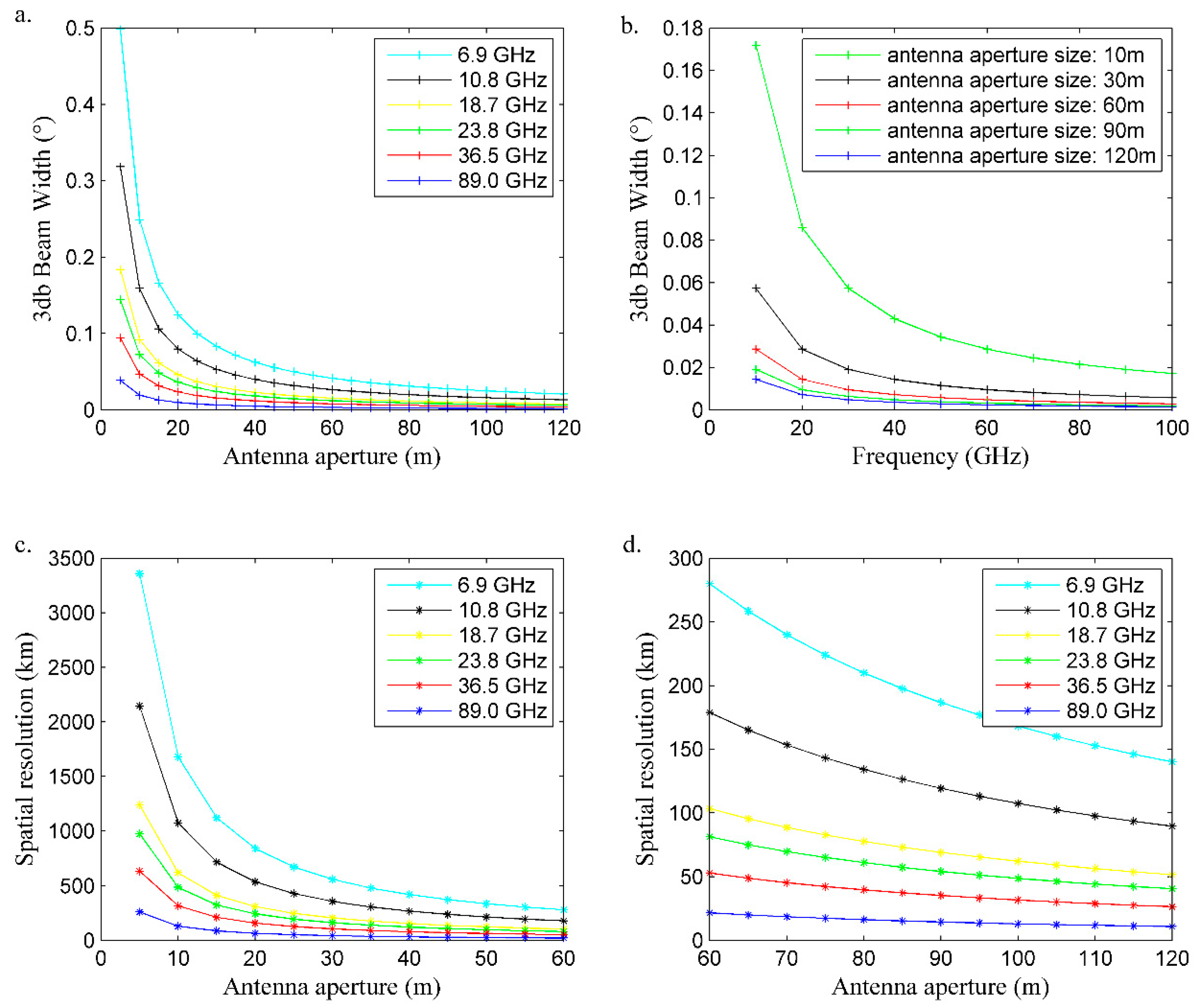
From Equations (3)–(12), the half-power beam width of the antenna can be seen to be an important parameter of the MBMR sensor that directly affects the integral range of the output brightness temperature of the antenna; thus, the parameter was analyzed from the frequency of microwaves and the antenna aperture size, as represented in Figure 6a–b. With the increase of the antenna aperture size, the half-power beam width of the antenna decreases, and the integration range for obtaining the output bright temperature of the antenna decreases (Figure 6a). Thus, the instantaneous field of view (IFOV) of the Moon-based sensor decreases as the antenna aperture increases. In addition, the half-power beam width of the antenna is related to the frequency, and the higher the frequency, the smaller the half power beam width, such as 6.9, 10.8, 18.7, 23.8, 36.5 and 89.0 GHz (Figure 6b). Accordingly, the IFOV of the Moon-based sensor decreases with the increasing frequency. The half-power beam width of the antenna of existing spaceborne microwave radiometers is generally between 0.2° and 2.2°, while, as can be seen in Figure 6a, the half-power beam width of the MBMR is much smaller than the existing size. When the antenna aperture size is set as 10 m, the half-power beam widths at frequencies of 6.9, 10.8, 18.7, 23.8, 36.5 and 89.0 GHz are 0.25°, 0.16°, 0.09°, 0.07°, 0.04° and 0.02°, respectively. As the antenna aperture size increases to 60 m, the half-power beam width of the six frequencies basically remains 0.04°, 0.03°, 0.02°, 0.01°, 0.01° and 0.003°, respectively, indicating that it is much smaller than the parameter of the spaceborne microwave radiometer. The phenomenon is closely related to the difference in the characteristics of the two different Earth observation platforms. The orbital height of existing satellite observation platform is usually about 700–950 km, and the average height of the MEO platform is about 380,000 km. The increase in orbital height would require higher sensor performance, thus causing unique antenna parameters for the MBMR.
For the microwave radiometer with cone scanning, the IFOV at any moment is closely related to the spatial resolution, which has to meet the requirements of different applications; thus, the spatial resolution of the microwave radiometer from the MEO platform under different antenna aperture sizes was analyzed as shown in Figure 6c–d. It can be seen that Moon-based sensors have a lower spatial resolution than the existing satellites with the same antenna aperture size. The spatial resolution increases with the increasing antenna aperture, and high spatial resolution data can obtain more accurate LST estimations. However, the aperture size of the antenna cannot be increased indefinitely due to the restricted manufacture process of sensors, causing a certain gap between the spatial resolution of the MEO platform and satellite observation. When the antenna aperture size is set as 20 m, the spatial resolutions of 6.9, 10.8, 18.7, 23.8, 36.5 and 89.0 GHz channels are 840 km, 536 km, 309 km, 243 km, 158 km and 65 km, respectively (Figure 6c). As the antenna aperture increases to 60 m, the spatial resolutions of the six different frequency channels are 284 km, 181 km, 105 km, 82 km, 53 km and 22 km, respectively (Figure 6c). Based on the existing study on LST retrieval from passive microwave remote sensing data, the spatial resolution of different frequencies should be less than 50 km. Therefore, the 60 m antenna aperture cannot satisfy the requirements of LST estimation for the MEO platform, and the size should be increased. When the antenna aperture size is 120 m, the spatial resolutions of six frequency channels are about 141 km, 90 km, 52 km, 40 km, 26 km and 10 km, respectively (Figure 6d). Three frequencies (23.8, 36.5 and 89.0 GHz) have a spatial resolution of less than 50 km, and one frequency (18.7 GHz) has a spatial resolution of approximately 50 km. The spatial resolutions of 6.9 and 10.8 GHz channels are larger than 90 km, which is far from meeting the requirements of LST inversion. In order to increase the spatial resolution of the two frequencies, the antenna aperture size should be increased. However, the antenna aperture size needs highly advanced sensor manufacturing technology and a high manufacturing cost. Therefore, these two frequencies are not suitable for the MEO platform, and the antenna aperture size should not be less than 120 m. At this time, the MBMR has a suitable spatial resolution for LST retrieval applications.
From the LST estimation results for the MEO platform in Section 3.1, the frequencies of 18.7 GHz, 23.8 GHz and 36.5 GHz can be seen to be suitable to retrieve LST for the MEO platform, and these three frequencies are selected as the bands of the MBMR sensor. Combining the analysis of the spatial resolution of different frequencies, 6.9 and 10.8 GHz have a lower image quality than other frequencies with the same conditions, and so they are not suitable for LST retrieval from the MEO platform. Furthermore, the water has a low dielectric constant and a small radiation thickness at 89.0 GHz, which can be used to calculate the effect of water vapor; the frequency is therefore essential for the MEO platform. In general, 18.7, 23.8, 36.5 and 89.0 GHz frequencies are suitable bands for MBMR. The existing spaceborne microwave radiometers usually include horizontal and vertical polarizations, which not only contain essential information for LST retrieval from passive microwave data but also contribute to obtaining necessary information about sea surface temperature, cloud water content, precipitation intensity, atmospheric temperature, wind, ozone, aerosol NOx and other atmospheric trace components. The two polarizations are indispensable for MBMRs, and the bandwidth selects the same value as the Advanced Microwave Scanning Radiometer for Earth Observing System (EOS) (AMSR-E).
The orbit of the MEO platform is the elliptical Moon’s orbit; that is, it orbits around the Earth from west to east. The average orbit height is 384,403 km, and perigee and apogee are 363,300 km and 405,493 km, respectively. To evaluate the effect of the Moon-based orbit height changes on the Moon-based microwave imaging results, the relationship between the spatial resolution and orbit height is analyzed in this study, as shown in Figure 7. When the antenna aperture size is 120 m, the spatial resolutions of the perigee at 18.7, 23.8, 36.5 and 89.0 GHz channels are 48 km, 38 km, 25 km and 10 km, while the spatial resolutions of the apogee are 54 km, 42 km, 27 km and 11 km, respectively. During the operation of the MEO platform, the spatial resolution of the Moon-based microwave image will reduce a little from perigee to apogee, and the higher the frequency, the smaller the variation. In general, the change of the orbital height of the MEO platform has little effect on the Moon-based imaging results.
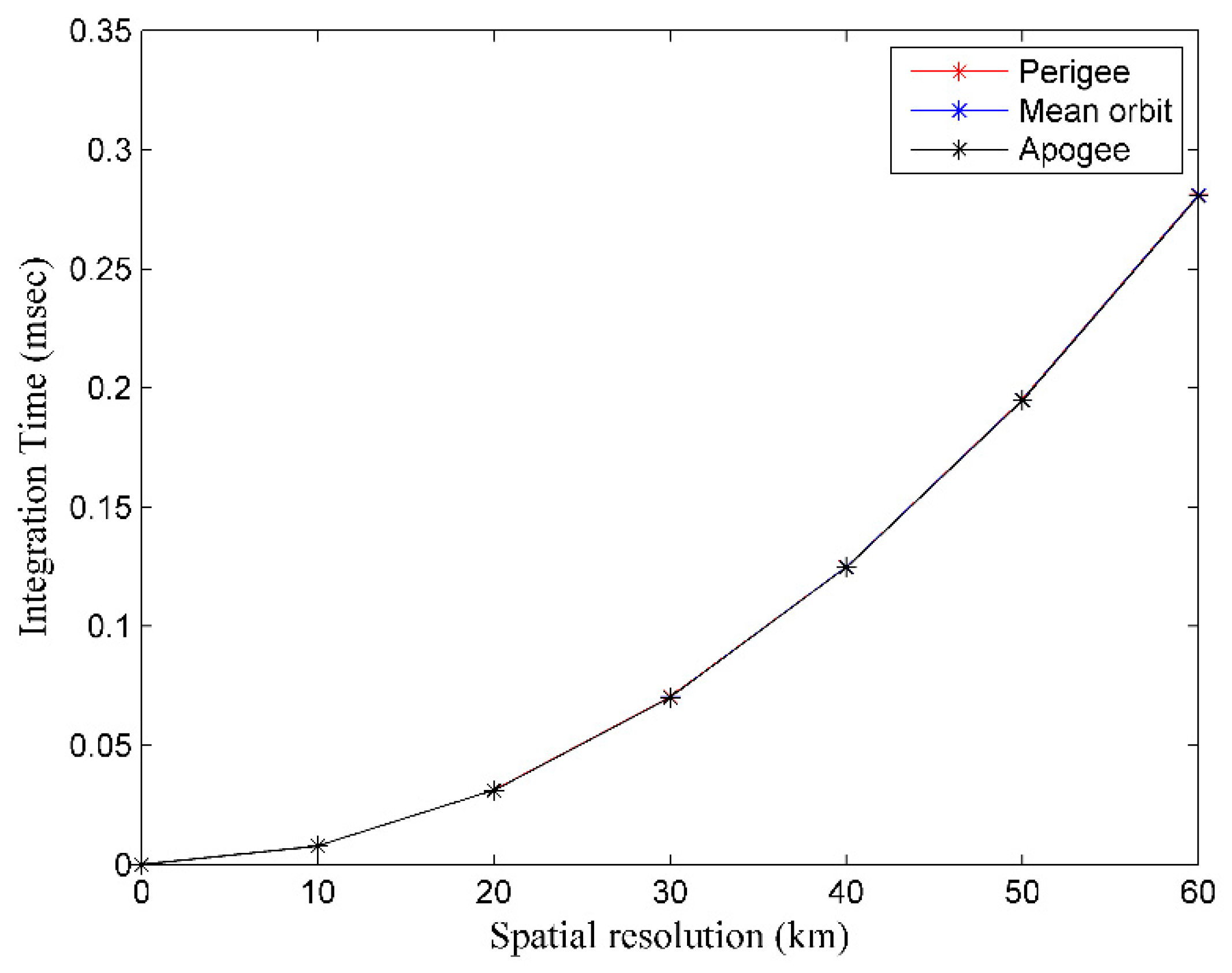
The integration time of MBMR is also an important parameter. Figure 8 shows the change of the integration time of MBMR with the spatial resolution. It can be seen that the integration time decreases with the increase of the spatial resolution. This is because the IFOV decreases when the spatial resolution increases, and a small IFOV requires a short integration time for the MBMR. In addition, the change of the orbital height of the MEO platform has little effect on the integration time.
Based on the application of the MEO platform, the antenna aperture is set as 120 m and the spatial resolutions of the four frequencies are 52, 40, 26 and 10 km, respectively. The integration time is 0.19, 0.12, 0.03 and 0.01 ms, respectively. Considering the characteristic of Moon-based microwave imaging, the scanning angle of the MBMR is 1.90° in theory, which can be obtained from the relative position between the Earth and the Moon. Based on Equation (18), the temperature sensitivity is estimated as 0.7, 0.6, 0.7 and 1.2 K. Therefore, based on the requirement of the LST retrieval application for the MEO platform, the optimal values of bands, bandwidth, polarization mode, half power beam width of antenna, scanning angle, antenna aperture size, temperature sensitivity, spatial resolution and the integration time of the MBMR system are represented in Table 1.
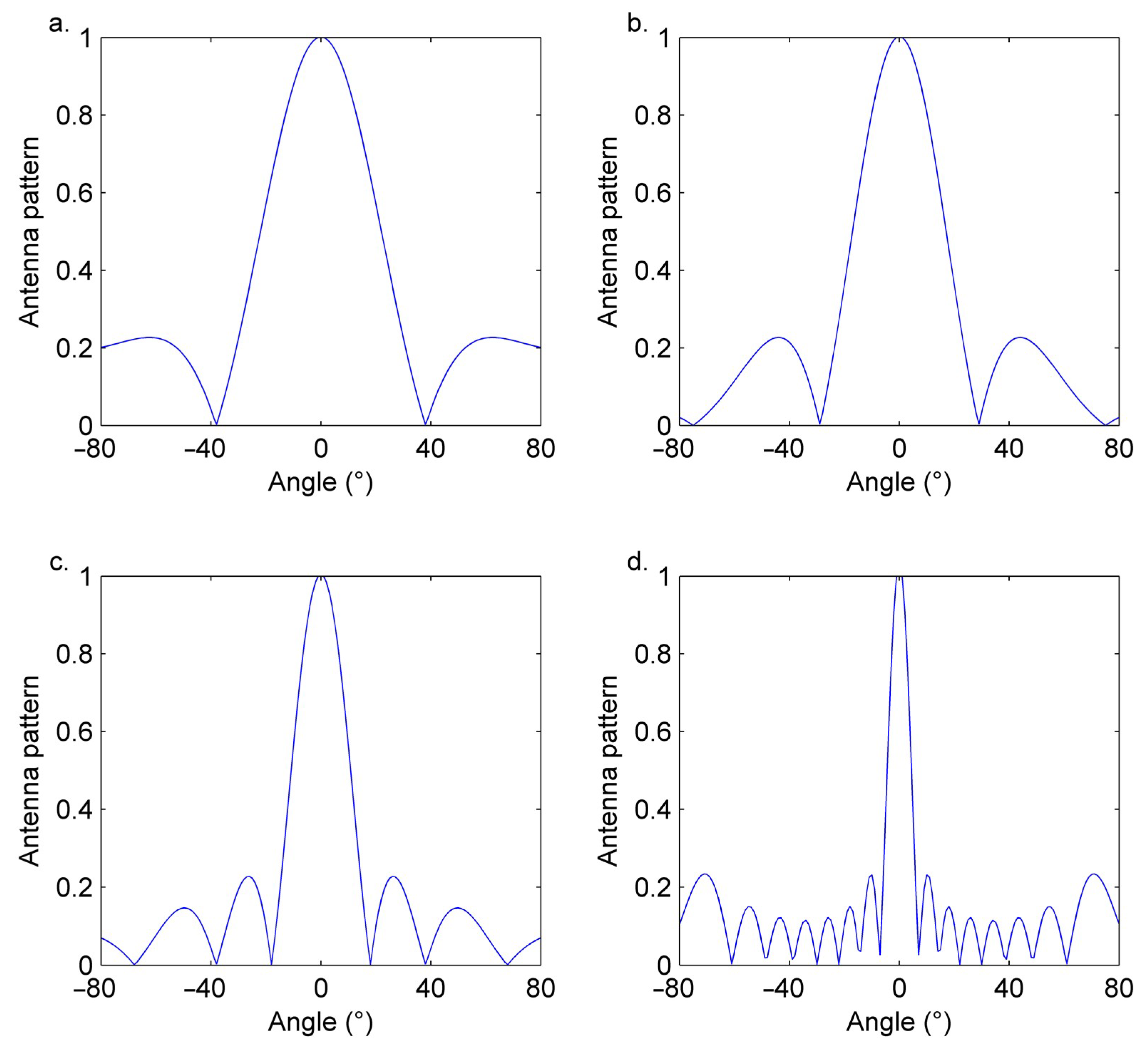
Further, the antenna patterns of 18.7 GHz, 23.8 GHz, 36.5 GHz and 89.0 GHz were simulated as shown in Figure 9. With the increase of frequency, the attenuation rate of the pattern becomes faster and the convergence is improved.
4. Discussion
4.1. Comparison with the Existing Spaceborne Microwave Radiometers
The current main microwave radiometers include the Nimbus 7 Scanning Multichannel Microwave Radiometer (SMMR), the Defense Meteorological Satellite Program (DMSP) Special Sensor Microwave Imager (SSM/I), the Advanced Microwave Scanning Radiometer (AMSR-E) on the Earth Observing System (EOS) Aqua satellite and the Microwave Radiation Imager (MWRI) carried by the FengYun-3 satellite. This paper compared the four sensors and the MBMR, and the main instrument parameters of the five sensors are shown in Table 2. The orbital heights of spaceborne microwave radiometers are less than 1000 km, and the MBMR has a 384,400 km average orbital height. The increase in orbital height would require higher sensor performance, thus causing unique antenna parameters for the MBMR. The antenna aperture sizes of the SMMR, SSM/I, AMSR-E, and MWRI are 0.79, 0.6, 1.6 and less than 2 m, respectively. However, due to the unique orbital characteristics of the MEO platform, the antenna aperture size of MBMR is suitable to be 120 m. SMMR and SSM/I mainly study the ocean and atmosphere, with a spatial resolution of about 140 km, while AMSR-E, MWRI and MBMR are mainly used for research on the land surface, sea surface, vegetation, atmosphere, etc. From the comparison of the spatial resolution, it can be seen that the image quality of the MBMR is the same as the existing AMSR-E and MWRI, which can be applicable for LST retrieval application.
Furthermore, 120 m is the optimal value for the theoretical simulation of the MBMR antenna aperture size, and the parameter may be adjusted by the limited sensor manufacturing technology when the MBMR sensor system is designed. Once the antenna aperture size is changed, the corresponding image quality of MBMR will be affected to a certain extent. The spatial resolution and image quality increases with the increase of antenna aperture size.
4.2. Comparison of LST Inversions between Spaceborne and Moon-Based Earth Observation Platforms
In general, the images measured by the current microwave radiometers extend in a long strip along the track, and the global LST can be obtained by mosaicking multiple LST retrieval images in a day. Due to the different acquisition times of various images (Universal Time Coordinated and local time), the LST results cannot satisfy the demands for spatial and temporal consistency in global observation. This phenomenon is related to the limited scan width, orbital height and sensor manufacturing technology. The scope of existing satellites is small due to the limited orbital height, and the scan widths of the SMMR, SSM/I, AMSR-E, and MWRI are 780, 1400, 1445 and 1400 km, respectively. However, the scan width of MBMR sensors reach up 20,000 km, which is half of the circumference of the Earth, indicating that each image acquired at the same Universal Time Coordinated by the MEO platform can cover half of the Earth’s surface in theory. Therefore, the MEO platform is suitable to measure global large-scale scientific phenome non, such as solid Earth dynamics, energy budgets, the Earth’s environmental systems and the Earth–space environment, et al. [8].
Based on the global LST estimations from the MEO platform at 1:00–24:00, it can be seen that the imaging position changes continuously from east to west with the relative movement of the Earth and Moon, and it takes about 13 h for the Moon-based platform to acquire a complete observation of the Earth. Moreover, the MEO platform can continuously monitor the surface for about 10 h, 13 h and exceeding 13 h in low-latitude areas, mid-latitude areas and high latitude areas, respectively. This indicates that the MEO platform can offer comprehensive, continuous and long-term Earth observation, and provides a new perspective for monitoring global LST.
5. Conclusions
In this study, to explore whether a microwave radiometer is suitable for the MEO platform, parts of the system parameters of MBMRs are analyzed in the context of land surface temperature retrieval application. First, the LST estimations from the lunar base were obtained using a presented Moon-based LST retrieval method. Results show that the LST from the Moon-based platform covers half of the Earth’s surface with a viewing zenith angle of 0–90°, and the Moon-based imaging position changes continuously from east to west with the relative movement of the Earth and the Moon. The Moon-based Earth observation platform can monitor low-latitude regions, mid-latitude regions, and high-latitude regions for about 10 h, 13 h and longer than 13 h in a day, respectively. This indicates that the MEO platform provides a new perspective for monitoring global LST. In addition, the FY-2 thermal infrared LST data were selected to evaluate the accuracy of LST estimations, and results showed that the average errors of the six frequencies were 8.61, 8.395, 6.975, 6.13, 7.295 and 8.235 K, and the RMSEs were 4.255, 3.74, 4.225, 3.845, 4.19 and 4.14 K, respectively.
Then, based on the LST estimation results, some design parameters of MBMRs, such as the half-power beam width of the aperture, the aperture size of the antenna, the spatial resolution, the temperature sensitivity, the integration time of the radiometer system, the observation frequency and the polarization mode, were analyzed. For an MBMR with cone scanning, the half-power beam width of the antenna decreases with the increase of antenna aperture size, as does the IFOV of the Moon-based sensor. Thus, the spatial resolution of the MEO platform increases with the increasing antenna aperture size, and the integration time of the microwave radiometer system continues to decrease. However, the aperture size of the antenna cannot be increased indefinitely due to the restricted manufacture process of sensors. Finally, the antenna aperture size is selected as 120 m, and the bands include 18.7, 23.8, 36.5 and 89.0 GHz, each with horizontal and vertical polarization. The spatial resolutions of the four frequency channels are 10m, 26, 40 and 52 km, the half-power beam widths of the antennas are 0.002°, 0.004°, 0.006° and 0.007°, and the integration time is 0.01, 0.03, 0.12 and 0.19 ms, respectively. The scanning angle for Moon-based Earth observation is 1.9°.
Further, the paper compared the main parameters of four spaceborne microwave radiometers (SMMR, SSM/I, AMSR-E and MWRI) and MBMR. Results showed that the antenna aperture size of MBMR is much larger than other radiometers due to the 384,400 km average orbital height. A size of 120 m is the optimal MBMR antenna aperture size for theoretical simulation, and the parameter may be adjusted by the limited sensor manufacturing technology when the MBMR sensor system is designed. Once the antenna aperture size is changed, the Moon-based image quality will be affected to a certain extent. As part of the MEO study, the LST retrieval and system parameter analysis of the MBMR will help to estimate LST from MEO data and support the design of the MBMR system.
Author Contributions
Conceptualization, L.Y.; data curation, L.Y.; formal analysis, L.Y.; funding acquisition, J.L.; investigation, L.Y.; methodology, L.Y.; project administration, J.L.; resources, J.L.; software, L.Y.; supervision, J.L.; validation, L.Y.; visualization, L.Y.; writing—original draft, L.Y. and J.L.; writing—review and editing, L.Y. and J.L. All authors have read and agreed to the published version of the manuscript.
Funding
This research was funded by the National Natural Science Foundation of China [grant number 41590855] and the Key Research Program in Frontier Science of the Chinese Academy of Sciences [grant number QYZDY-SSW-DQC026].
Acknowledgments
We are grateful to students and teachers of our research group for providing help and writing assistance. We are also grateful to the National Satellite Meteorological Center of China Meteorological Administration and the International Telecommunication Union Recommendation for providing FY2 thermal infrared LST data and the P Series P.676-8 recommendation. We would like to thank the anonymous reviewers for their voluntary work and the constructive comments which helped to improve the manuscript.
Conflicts of Interest
The authors declare no conflict of interest.
References
- Corradini, S.; Silvestri, M.; Musacchio, M.; Caltabiano, T.; Prestifilippo, M.; Guerrieri, L.; Stelitano, D.; Merucci, L.; Salerno, G.; Scollo, S.; et al. The Christmas 2018 Etna Eruption: Real Time Monitoring Using Geostationary and Polar Orbit Satellites Systems and Products Validation. In Proceedings of the IGARSS 2019-2019 IEEE International Geoscience and Remote Sensing Symposium, Yokohama, Japan, 28 July–2 August 2019; pp. 9310–9313. [Google Scholar]
- Nie, C.; Liao, J.; Shen, G.; Duan, W. Simulation of the land surface temperature from moon-based Earth observations. Adv. Space Res. 2019, 63, 826–839. [Google Scholar] [CrossRef]
- Valero, F.P.; Herman, J.; Minnis, P. DSCOVR, a new approach to Earth Sciences from Space. Cosp 2006, 36, 1653. [Google Scholar]
- Valero, F.P. Lagrange Point Missions: The Key to Next-Generation Integrated Earth Observations. DSCOVR Innovation. AGUFM 2016, 2016, A21K-02. [Google Scholar]
- Zhang, D.W. Study on Moon-Earth Observation Methodology for Global Change. Ph.D. Thesis, East China Normal University, Shanghai, China, 2012. (In Chinese). [Google Scholar]
- Ding, Y.; Guo, H.; Liu, G. Potential applications of the moon based synthetic aperture radar for earth observation. In Proceedings of the 2013 IEEE International Geoscience and Remote Sensing Symposium IGARSS, Melbourne, VIC, Australia, 21–26 July 2013; pp. 1767–1769. [Google Scholar] [CrossRef]
- Guo, H.; Liu, G.; Ding, Y.; Zou, Y.; Huang, S.; Jiang, L.; Gensuo, J.; Lv, M.; Ren, Y.; Ruan, Z.; et al. Moon-based earth observation for large scale geoscience phenomena. In Proceedings of the 2016 IEEE International Geoscience and Remote Sensing Symposium (IGARSS), Beijing, China, 10–15 July 2016; pp. 3705–3707. [Google Scholar] [CrossRef]
- Guo, H.; Liu, G.; Ding, Y. Moon-based Earth observation: Scientific concept and potential applications. Int. J. Digit. Earth 2018, 11, 546–557. [Google Scholar] [CrossRef]
- Ren, Y.; Guo, H.; Liu, G.; Ye, H. Simulation Study of Geometric Characteristics and Coverage for Moon-Based Earth Observation in the Electro-Optical Region. IEEE J. Sel. Top. Appl. Earth Obs. Remote Sens. 2017, 10, 2431–2440. [Google Scholar] [CrossRef]
- Ye, H.; Guo, H.; Liu, G. Observation parameters design of moon-based earth observation sensors for monitoring three-polar regions. In Proceedings of the 2017 IEEE International Geoscience and Remote Sensing Symposium (IGARSS), Fort Worth, TX, USA, 23–28 July 2017; pp. 5755–5758. [Google Scholar]
- Guo, H.; Ye, H.; Liu, G.; Dou, C.; Huang, J. Error analysis of exterior orientation elements on geolocation for a Moon-based Earth observation optical sensor. Int. J. Digit. Earth 2020, 13, 374–392. [Google Scholar] [CrossRef]
- Li, T.; Guo, H.; Zhang, L.; Nie, C.; Liao, J.; Liu, G. Simulation of Moon-based Earth observation optical image processing methods for global change study. Front. Earth Sci. 2019, 14, 236–250. [Google Scholar] [CrossRef]
- Yuan, L.; Liao, J. Exploring the influence of various factors on microwave radiation image simulation for Moon-based Earth observation. Front. Earth Sci. 2019, 14, 430–445. [Google Scholar] [CrossRef]
- Jiang, H.; Dong, J.; Jiang, L.; Li, D. Moon-Based SAR for Earth Observation and Its Spatial Baseline Decorrelation in Repeat-Pass Interferometry. In Proceedings of the IGARSS 2019-2019 IEEE International Geoscience and Remote Sensing Symposium, Yokohama, Japan, 28 July–2 August 2019; pp. 1705–1708. [Google Scholar]
- Guo, H.; Ding, Y.; Liu, G.; Zhang, D.; Fu, W.; Zhang, L. Conceptual study of lunar-based SAR for global change monitoring. Sci. China Earth Sci. 2014, 57, 1771–1779. [Google Scholar] [CrossRef]
- Ren, Y.; Guo, H.; Liu, G.; Ye, H.; Ding, Y.; Zhang, D.; Ruan, Z.; Lv, M. Simulation of moon-based observation for large-scale Earth science phenomena. In Proceedings of the 2016 IEEE International Geoscience and Remote Sensing Symposium (IGARSS), Beijing, China, 10–15 July 2016; pp. 6253–6256. [Google Scholar] [CrossRef]
- Shen, G.; Guo, H.; Liu, G.; Zhang, L.; Huang, J. Geometry Numerical Simulation and Analysis for Moon-Based Earth Observation. IEEE J. Sel. Top. Appl. Earth Obs. Remote Sens. 2020, 99, 1. [Google Scholar] [CrossRef]
- McFarland, M.J.; Miller, R.L.; Neale, C.M.U. Land surface temperature derived from the SSM/I passive microwave brightness temperatures. IEEE Trans. Geosci. Remote Sens. 1990, 28, 839–845. [Google Scholar] [CrossRef]
- Weng, F.; Grody, N.C. Physical retrieval of land surface temperature using the special sensor microwave imager. J. Geophys. Res. Space Phys. 1998, 103, 8839–8848. [Google Scholar] [CrossRef]
- Fily, M.; Royer, A.; Goïta, K.; Prigent, C. A simple retrieval method for LST and fraction of water surface determination from satellite microwave brightness temperatures in sub-arctic areas. Remote Sens. Environ. 2003, 85, 328–338. [Google Scholar] [CrossRef]
- Mao, K.; Shi, J.; Li, Z.; Qin, Z.; Jia, Y. Land surface temperature and emissivity retrieved from AMSR passive micro-wave data. IEEE Int. Geosci. Remote Sens. Symp. 2005, 4, 2247–2249. [Google Scholar] [CrossRef]
- Mao, K.; Shi, J.; Tang, H.; Guo, Y.; Qiu, Y.; Li, L. A neural-network technique for retrieving land surface temperature from AMSR-E passive microwave data. In Proceedings of the 2007 IEEE International Geoscience and Remote Sensing Symposium, Barcelona, Spain, 23–28 July 2007; pp. 4422–4425. [Google Scholar] [CrossRef]
- Mao, K.B.; Shi, J.C.; Li, Z.L.; Qin, Z.H.; Li, M.C.; Xu, B. A physics-based statistical algorithm for retrieving LST from AMSR-E passive microwave data. Sci. China 2007, 50, 1115–1120. [Google Scholar] [CrossRef]
- Mao, K.; Tang, H.J.; Zhang, L.X.; Li, M.C.; Guo, Y.; Zhao, D.Z. A method for retrieving soil moisture in Tibet region by utilizing microwave index from TRMM/TMI data. Int. J. Remote Sens. 2008, 29, 2903–2923. [Google Scholar] [CrossRef]
- Gao, H.; Fu, R.; Dickinson, R.E.; Juarez, R.I.N. A practical method for retrieving LST from AMSR-E over the amazon forest. IEEE Trans. Geosci. Remote Sens. 2007, 46, 193–199. [Google Scholar] [CrossRef]
- Holmes, T.R.H.; De Jeu, R.A.M.; Owe, M.; Dolman, A.J. Land surface temperature from Ka band (37 GHz) passive microwave observations. J. Geophys. Res. Space Phys. 2009, 114, 04113. [Google Scholar] [CrossRef] [Green Version]
- Basist, A.; Grody, N.C.; Peterson, T.C.; Williams, C.N. Using the special sensor microwave/imager to monitor LSTs, wetness, and snow cover. J. Appl. Meteorol. Clim. 1998, 37, 888–911. [Google Scholar] [CrossRef]
- Zhou, F.-C.; Li, Z.-L.; Wu, H.; Duan, S.-B.; Song, X.; Yan, G. A Practical Two-Stage Algorithm for Retrieving Land Surface Temperature from AMSR-E Data—A Case Study Over China. IEEE J. Sel. Top. Appl. Earth Obs. Remote Sens. 2018, 11, 1939–1948. [Google Scholar] [CrossRef]
- Huang, C.; Duan, S.-B.; Jiang, X.-G.; Han, X.-J.; Leng, P.; Gao, M.-F.; Li, Z.-L. A physically based algorithm for retrieving land surface temperature under cloudy conditions from AMSR2 passive microwave measurements. Int. J. Remote Sens. 2019, 40, 1828–1843. [Google Scholar] [CrossRef]
- Zhang, Q.; Cheng, J. An Empirical Algorithm for Retrieving Land Surface Temperature From AMSR-E Data Considering the Comprehensive Effects of Environmental Variables. Earth Space Sci. 2020, 7. [Google Scholar] [CrossRef] [Green Version]
- Yuan, L.; Liao, J. A Physical-Based Algorithm for Retrieving Land Surface Temperature from Moon-Based Earth Observation. IEEE J. Sel. Top. Appl. Earth Obs. Remote Sens. 2020, 13, 1856–1866. [Google Scholar] [CrossRef]
- Ashkaliyev, Y.F. Radio-wave attenuation during propagation through the ionosphere in the 3 to 100 MHZ range. Geomagn. Aeron. 1972, 12, 309. [Google Scholar]
- Cai, W.X. Research on Propagation Characteristics of Radio Waves in Heating Ionosphere. Ph.D. Thesis, XIDIAN University, Xi’an China, 2015. [Google Scholar]
- Devi, M.I.; Khan, I.; Rao, D.N.M. A study of VLF wave propagation characteristics in the earth-ionosphere waveguide. Earth Planets Space 2008, 60, 737–741. [Google Scholar] [CrossRef] [Green Version]
- Lawrence, R.; Little, C.; Chivers, H. A survey of ionospheric effects upon earth-space radio propagation. Proc. IEEE 1964, 52, 4–27. [Google Scholar] [CrossRef]
- Li, J.T. Study on some Problems for Radio Wave Propagating and Scattering through Space Plasma. Ph.D. Thesis, Xi’an University, Xi’an, China, 2012. [Google Scholar]
- Lu, J.P. Absorption Attenuation of Electromagnetic Waves in Plasma. Ph.D. Thesis, Beijing Institute of Technology, Beijing, China, 2004. [Google Scholar]
- Chen, S.; Chen, X.-Z.; Chen, W.-Q.; Su, Y.; Li, D. A simple retrieval method of land surface temperature from AMSR-E passive microwave data—A case study over Southern China during the strong snow disaster of 2008. Int. J. Appl. Earth Obs. Geoinform. 2011, 13, 140–151. [Google Scholar] [CrossRef]
- Goïta, K.; Royer, A. Combination of passive microwave and thermal infrared for the retrieval and analysis of microwave emissivities and temperature. In Proceedings of the 2002 IEEE International Geoscience and Remote Sensing Symposium, Toronto, ON, Canada, 24–28 June 2002. [Google Scholar] [CrossRef]
- Liu, Z.-L.; Wu, H.; Qiu, S.; Jia, Y.-Y.; Li, Z.-L. Determination of Land Surface Temperature from AMSR-E data for bare surfaces. In Proceedings of the 2010 IEEE International Geoscience and Remote Sensing Symposium, Honolulu, HI, USA, 25–30 July 2010; pp. 3011–3014. [Google Scholar] [CrossRef]
- Royer, A.; Poirier, S. Surface temperature spatial and temporal variations in North America from homogenized satellite SMMR-SSM/I microwave measurements and reanalysis for 1979–2008. J. Geophys. Res. Space Phys. 2010, 115, 462–474. [Google Scholar] [CrossRef]
- Bergada, M.; Brotons, P.; Camacho, Y.; Díez, L.; Gamonal, A.; Garcia, J.L.; Gonzalez, R.; Pacheco, A.; Palacios, M.A.; Klein, U. Design and development of the Sentinel-3 Microwave Radiometer. Remote Sens. 2010, 7826. [Google Scholar] [CrossRef]
- Zhao, S.; Zhang, L.; Zhang, Z. Design and Test of a New Truck-Mounted Microwave Radiometer for Remote Sensing Research. In Proceedings of the 2008 IEEE International Geoscience and Remote Sensing Symposium, Boston, MA, USA, 7–11 July 2008. [Google Scholar] [CrossRef]
- Sun, J.; Zhao, K.; Jiang, T. A Multipoint Correction Method for Environmental Temperature Changes in Airborne Double-Antenna Microwave Radiometers. Sensors 2014, 14, 7820–7830. [Google Scholar] [CrossRef] [Green Version]
- Schwank, M.; Wiesmann, A.; Werner, C.; Mätzler, C.; Weber, D.; Murk, A.; Völksch, I.; Wegmüller, U. ELBARA II, an L-Band Radiometer System for Soil Moisture Research. Sensors 2010, 10, 584–612. [Google Scholar] [CrossRef] [PubMed]
- Wang, J. Research on the Key Technology of Miniaturized Microwave Radiometers for Microsatellites. Ph.D. Thesis, National Space Science Center, Chinese Academy of Sciences, Beijing, China, 2019. [Google Scholar]
Figure 1.
The microwave radiometer imaging principle from the Moon-based Earth observation (MEO) platform.
Figure 1.
The microwave radiometer imaging principle from the Moon-based Earth observation (MEO) platform.

Figure 2.
The scanning method of the Moon-based microwave radiometer (MBMR).

Figure 3.
The land surface temperature (LST) estimation results from the lunar base at 1:00–24:00 on 1 January 2018.
Figure 3.
The land surface temperature (LST) estimation results from the lunar base at 1:00–24:00 on 1 January 2018.


Figure 4.
The accuracy analysis of Moon-based LST estimations compared with Fengyun 2 (FY-2) F thermal infrared data, representing the results of (a) 6.9, (b) 10.8, (c) 18.7, (d) 23.8, (e) 36.5 and (f) 89.0 GHz channels.
Figure 4.
The accuracy analysis of Moon-based LST estimations compared with Fengyun 2 (FY-2) F thermal infrared data, representing the results of (a) 6.9, (b) 10.8, (c) 18.7, (d) 23.8, (e) 36.5 and (f) 89.0 GHz channels.

Figure 5.
The accuracy analysis of Moon-based LST estimations compared with FY-2G thermal infrared data, representing the results of (a) 6.9, (b), 10.8, (c), 18.7, (d), 23.8, (e) 36.5 and (f) 89.0 GHz channels.
Figure 5.
The accuracy analysis of Moon-based LST estimations compared with FY-2G thermal infrared data, representing the results of (a) 6.9, (b), 10.8, (c), 18.7, (d), 23.8, (e) 36.5 and (f) 89.0 GHz channels.

Figure 6.
(a) The change of the half-power beam width with the antenna aperture; (b) the change of half-power beam width with the frequency; (c) the spatial resolution of MBMR under different antenna aperture sizes of 0–60 m; (d) the change of spatial resolution of MBMR with an antenna aperture size of 60–120 m.

Figure 7.
The change of spatial resolution with orbit height.

Figure 8.
The change of the integration time of MBMR with spatial resolution.

Figure 9.
The antenna pattern simulations at different frequencies. (a) 10.8 GHz; (b) 18.7 GHz; (c) 23.8; (d) 36.5 GHz.
Figure 9.
The antenna pattern simulations at different frequencies. (a) 10.8 GHz; (b) 18.7 GHz; (c) 23.8; (d) 36.5 GHz.


Table 1.
The optimal parameters of the MBMR system.
| Bands (GHz) | 18.7 | 23.8 | 36.5 | 89 |
| Bandwidth (MHz) | 200 | 400 | 1000 | 3000 |
| Polarization | Horizontal and vertical polarization | |||
| Half power beam width (°) | 0.007 | 0.006 | 0.004 | 0.002 |
| Scanning angle (°) | 1.90 | |||
| Temperature sensitivity (K) | 0.7 | 0.6 | 0.7 | 1.2 |
| Antenna aperture size/diameter (m) | 120 | |||
| Spatial resolution (km) | 52 | 40 | 26 | 10 |
| Integration time (ms) | 0.19 | 0.12 | 0.03 | 0.01 |
Table 2.
The main instrument parameters of the SMMR, SSM/I, AMSR-E, MWRI and MBMR.
| Parameters | SMMR 1 | SSM/I 2 | AMSR-E 3 | MWRI 4 | MBMR 5 |
|---|---|---|---|---|---|
| Frequency (GHz) | 6.6, 10.7, 18, 21, 37 | 19.3, 22.3, 37, 85.5 | 6.9, 10.7, 18.7, 23.8, 36.5, 89 | 10.7, 18.7, 23.8, 36.5, 89, 150 | 18.7, 23.8, 36.5, 89 |
| Polarization | Horizontal and vertical polarization | ||||
| Orbital height (km) | 955 | 860 | 705 | 836 | 384,400 |
| Viewing zenith angle (°) | 50.3 | 53.1 | 55 | 52–53 | 0–90 |
| Scan width (km) | 780 | 1400 | 1445 | 1400 | 20,000 |
| Antenna aperture size/diameter (m) | 0.79 | 0.6 | 1.6 | <2.0 | 120 |
| Spatial resolution (km) | 150 | 140 | 5–50 | 15~85 | 10~52 |
| Launch date | 1978 | 1987 | 2002 | 2008 | No |
1 Scanning Multichannel Microwave Radiometer. 2 Defense Meteorological Satellite Program (DMSP) Special Sensor Microwave Imager. 3 Advanced Microwave Scanning Radiometer on the Earth Observing System (EOS). 4 Microwave Radiation Imager. 5 Moon-based microwave radiometer.
Publisher’s Note: MDPI stays neutral with regard to jurisdictional claims in published maps and institutional affiliations. |
© 2020 by the authors. Licensee MDPI, Basel, Switzerland. This article is an open access article distributed under the terms and conditions of the Creative Commons Attribution (CC BY) license (http://creativecommons.org/licenses/by/4.0/).
Share and Cite
MDPI and ACS Style
Yuan, L.; Liao, J. Parametric Design of a Microwave Radiometer for Land Surface Temperature Retrieval from Moon-Based Earth Observation Platform. Remote Sens. 2020, 12, 4110. https://0-doi-org.brum.beds.ac.uk/10.3390/rs12244110
AMA Style
Yuan L, Liao J. Parametric Design of a Microwave Radiometer for Land Surface Temperature Retrieval from Moon-Based Earth Observation Platform. Remote Sensing. 2020; 12(24):4110. https://0-doi-org.brum.beds.ac.uk/10.3390/rs12244110
Chicago/Turabian StyleYuan, Linan, and Jingjuan Liao. 2020. "Parametric Design of a Microwave Radiometer for Land Surface Temperature Retrieval from Moon-Based Earth Observation Platform" Remote Sensing 12, no. 24: 4110. https://0-doi-org.brum.beds.ac.uk/10.3390/rs12244110
Note that from the first issue of 2016, this journal uses article numbers instead of page numbers. See further details here.