2. 3D Data Recording
There are a variety of methods to record archaeological phenomena during excavation and survey. Analogue methods record 3D information in relation to a grid placed over an area. A tape measure was often used to determine x and y coordinates with elevation measured in relation to a common datum, whether that is the ground level or survey marker. Dumpy levels, transits, plane-table alidades, and other instruments can improve precision and accuracy of these measurements. Beginning in the 1980s, the use of TS with built-in or external data loggers significantly reduced the amount of time it took to take measurements [
8,
9]. This resulted in an increase in the number of readings and, in turn, new excavation techniques [
9,
10]. Using TS, thousands of measurements can be taken in a relatively short time to create point-cloud data.
TS are now a common archaeological recording tool and are used in a range of contexts (e.g., [
11,
12]). This has been due to an increase in the interest and utilization of 3D data for the analysis of artefact distributions (e.g., [
13]) and topological analyses. While the recording of artefact positions has largely stayed within the purview of TS recording, recording 3D data related to landscapes and features has increasingly utilized LiDAR and structure from motion (SfM).
There are many archaeological applications of LiDAR which fall under two broad categories, airborne LiDAR survey (ALS) and terrestrial LiDAR survey (TLS). ALS has historically been done by aircraft at the landscape scale (see [
14] for a recent review) with more recent use of drones [
14,
15,
16,
17]. TLS involves the use of ground-based LiDAR systems; however, given the increasing use of drones for LiDAR capture, this division is becoming obscured as aerial drones capture data that terrestrial systems could have [
14]. Archaeological applications of TLS include small-scale landscape features such as mounds, but also smaller entities such as archaeological excavations [
18,
19,
20]. ALS and TLS create point clouds by aligning common points that are relative to what they are recording. A method for interpolating LiDAR data is simultaneous localization and mapping (SLAM), which creates a point cloud of an area relative to the position of the recording device within it and the features it records. In archaeology, SLAM is most commonly applied to built environments with architectural features [
21], but has also been used in underwater archaeology [
22].
Modelling using SfM, otherwise commonly referred to as photogrammetry (PG), is increasingly common in archaeological inquiry [
23]. This technique utilizes multiple photographs around a common object or feature to create a 3D point cloud, which can consist of thousands or hundreds of millions of points [
24]. Both objects [
1,
4] and features [
25,
26] are frequently digitized in this way, and photogrammetry is applied to excavations as well as wider built and natural landscape contexts [
27,
28,
29,
30]. These data are most commonly employed as aids for interpretation or for visualization as 2.5D objects, which is an otherwise 2D dataset that is represented as a 3D model, although some work has been done on making 3D volumes from the data (e.g., [
31]). Despite this, analytical applications of created volumes are generally lacking, a point we return to below.
There are known, yet generally unquantified, advantages and disadvantages to these three methods (TS, PG, and LIDAR (specifically SLAM)). PG provides an accurate alternative to other forms of recording such as total stations for surfaces [
32]. In other examples where data are collected on objects, PG was found to be more accurate than laser scanning [
3,
33]. In a comparison between ALS, PG, and radar for measuring water surface elevation, radar was found to be the most accurate but LIDAR vs. PG were similar [
34].
PG is also an efficient technique for acquiring data, as it generally takes up less physical space than other methods. The space available for recording may be a factor in this, as small spaces may be better captured with photogrammetry and can later be merged with wider larger scans obtained through TLS [
35]. PG models are also used to colorize data captured from ALS or TLS [
36,
37,
38] and, in some cases, enhance the resolution of particular features [
39]. Modern LiDAR systems such as SLAM, however, increasingly employ color capture without the use of PG [
40]. Despite the advances in LiDAR, PG is still generally less expensive than other approaches and, therefore, more widely accessible. This is particularly the case when it is applied terrestrially [
35].
All three methods (TS, PG, and LIDAR (specifically SLAM)) can be used to construct point clouds, which may in turn be triangulated into meshes. The point clouds generated by TS [
11] are generally coarse in comparison to PG or SLAM. Collecting smaller quantities of data, yet often enough for analysis, can be quicker with TS than the other methods. TS also has the advantage that it is generally quicker and more easily integrated into existing workflows for small areas. Obtaining large quantities of data via TS, however, can be much more time consuming in relation to PG and SLAM.
Where physical space is available and excavation areas allow, artefact provenance data can be extracted from 3D models [
32]. Time and excavation methods again have an influence here as the ability to pedestal objects may be limited by their density or the recording practice of only creating models at the interface of deposits or features. Time is also a factor, which is essential to consider when applying differing methodologies, as some are more labor intensive in-field, while others are labor intensive off-site. In the case of PG, Scott and colleagues [
31] highlight that in some cases, the amount of time taken to record and process a 3D model of small objects can be larger than the time taken to excavate the object.
3. Uses of 3D Data
Data collected with TS, PG, or LiDAR and the resultant 3D models are either displayed on their own or in conjunction with other forms of geospatial data in a geographical information system (GIS) interface [
2,
30,
41,
42]. With respect to the built environment, one of the frequent uses of 3D data is the reconstruction of buildings, which are used for visualization and analytical purposes [
26,
42,
43]. The data represented, however, are rarely actually “3D” and, instead, consist of what is referred to as “2.5D”. The key difference is that a 3D model has a bounded volume, it closes back on itself, whereas a 2.5D model does not. A common application of 2.5D models are landscapes, which in order to “close”, would require a model of the entire planet. Examples of 3D models would include an artefact where the whole object is represented or, in the case of this paper, a deposit identified during excavation.
Roosevelt and colleagues [
44] created volumes from PG 3D data to record deposits, and their stratigraphic relationships, however, do not suggest any analytical use for such volumes. Gavryushkina [
7] used ESRI ArcGIS to construct 3D volumes from deposit outlines that were extruded to create closed entities. They compared multiple methods of volume creation including triangulated irregular networks (TIN), minimum bounding volume, and digitized section drawings. It was found that the volumes calculated from each were different, the volumes from TINs were successful when available, but the construction method depended on the x and y alignment of the TINs, which as noted elsewhere, is not always the case [
6]. The minimum bounding volumes tended to over-represent the volume of the deposits, while the stratigraphic drawings were not carried out in enough frequency to capture the deposits in enough detail.
Interpreting stratigraphic relationships is one of the more frequently cited reasons for creating 3D excavation data [
45] and certainly has utility [
6,
46]. In addition, 3D data can be used to create deposit volumes for understanding differential patterning in artifact distributions. However, the construction of a deposit volume is contingent upon a number of factors including how data were collected and processed. The influence that these factors can have on the calculation of volumes and the interpretations from them requires further analysis. Here, we compare the use of triangulated meshes and convex hulls to model deposit surface areas and volumes created from TS, PG, and SLAM data.
4. Case Study: Waitetoke, Ahuahu Great Mercury Island
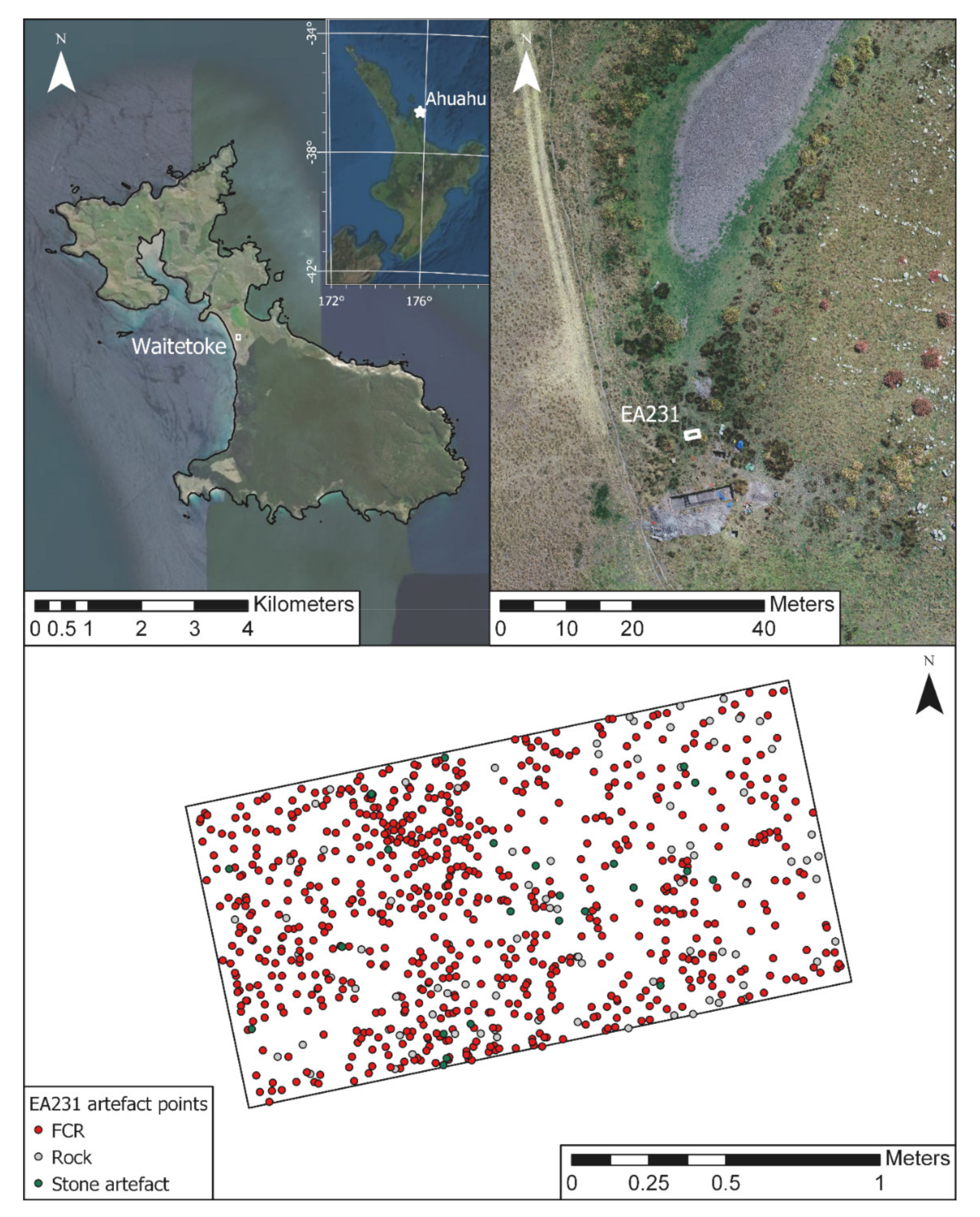
Ahuahu Great Mercury Island lies c. 5.5 km off the east coast of the Coromandel Peninsula of the North Island, Aotearoa New Zealand (
Figure 1). It is composed of elevated land to the north and south of volcanic origin with a central tombolo of sand. The island has considerable evidence for Māori occupation. Initial research on the island focused on pā (fortifications) around the coast in addition to the general identification of archaeological sites and features [
47,
48,
49,
50,
51]. Since 2012, the Ahuahu Great Mercury Island Project has carried out surveys and excavations across the northern half of the island with most attention focused around the tombolo area [
18,
52,
53,
54,
55,
56,
57,
58,
59,
60,
61].
Waitetoke (NZ SRS# T10/356) is a particular location of interest for understanding horticultural development on the island. It is in a swale between dunes and a hill slope at the southern end of the tombolo (
Figure 1). Excavations in 2012 at Waitetoke investigated a series of stone rows and rock-faced terraces on the slope to the south of a current mire. This area was used for kūmara (sweet potato;
Ipomoea batatas) production utilizing a number of different techniques [
52]. Shovel test pitting of the mire in 2012 and coring and excavation at EA200 in 2015 identified early evidence for taro (
Colocasia esculenta) production, and dating of sedge seeds associated with fire-cracked rock and charcoal provided a date of 1434–1488 CE (Wk47862, 469 ± 19, calibrated with SHCal20, 95.4% 516–462 BP) [
55,
57].
Excavations resumed at Waitetoke in 2019 and again in 2020 to further examine the extent of horticultural features to the southwest of the mire. Several excavations were done that identified a system of channels, small check dams or weirs, and anthropogenic garden sediments, all used in taro production. In April 2021, further excavations were carried out with the dual aim of determining the extent of the channel system as well as testing new recording practices. Here, we report on the methods of data acquisition utilized and test their applicability to the recording of one of the trenches, EA231 a 1 × 2m unit (
Figure 1).
Our recording practice at EA231 followed a spatial–hierarchical system that defines two base observations, objects and features [
61]. An object is defined as something that can be picked up and moved, and a feature is something that cannot, such as a channel feature. Objects and features are attributed to a deposit, defined as a homogenous sedimentary matrix, which in turn exists within an excavation area (EA). Each entity is given a unique identifier (UNID).
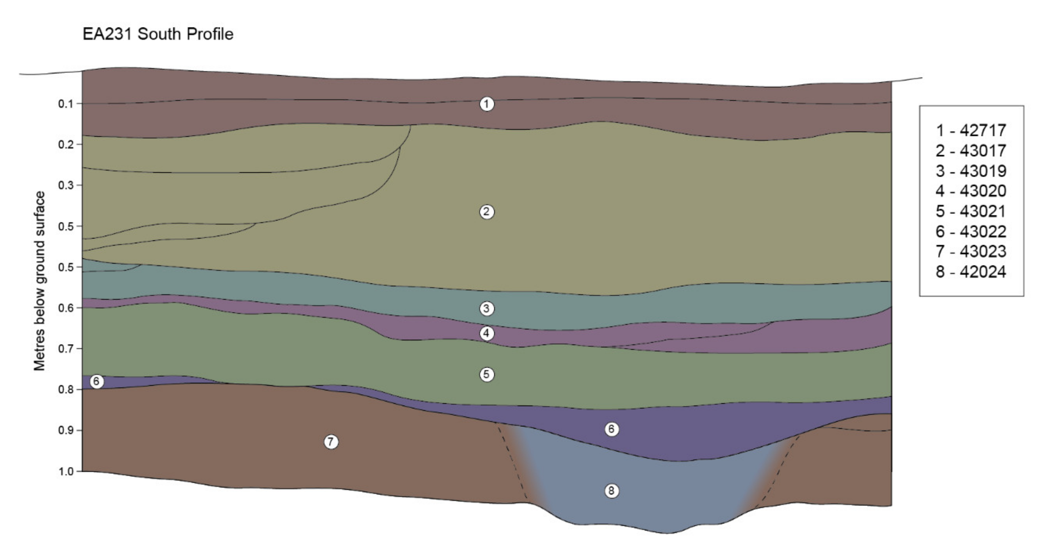
EA231 was excavated to investigate the extent of a secondary channel (Feature 30754) off the main channel system. During the excavation of EA231, eight primary sedimentary deposits were identified (
Figure 2), with an underlying culturally sterile deposit not modelled or shown in our analysis, aside from forming the base of layers 7 and 8. Additional deposits in EA231 were recorded during the excavation and when profiles were drawn, but these are not included in our analysis in this paper. Our field recording schema assigned a unique identifier (UNID) to the deposits, and a relative numbering system has been assigned for this analysis (
Table 1). Varying numbers of fire-cracked rock (FCR) and stone artefacts and rocks were recorded during excavation (
Table 1).
5. Data Acquisition and Processing
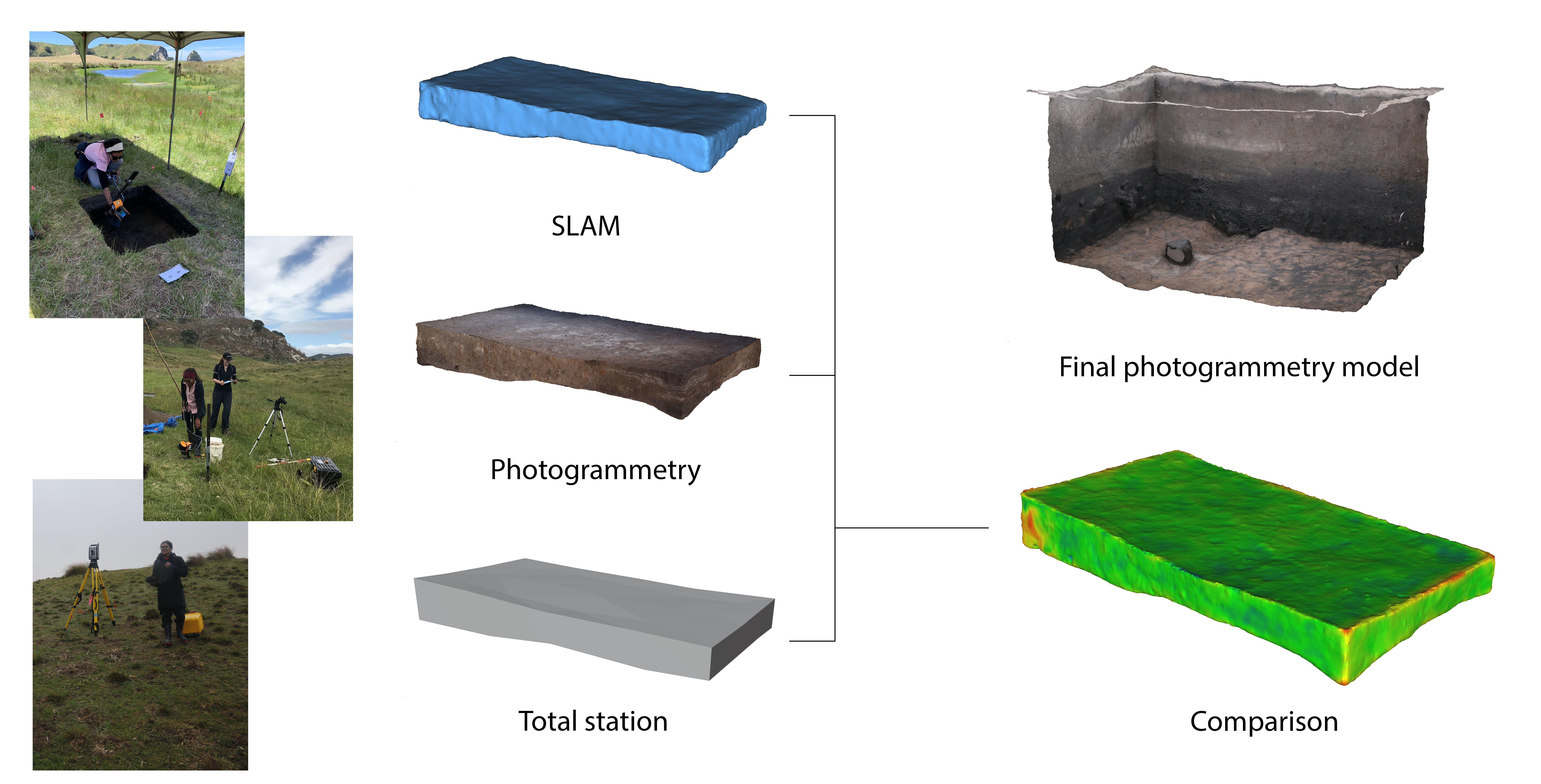
During the excavation of EA231, three methods of data acquisition (TS, PG, and LIDAR (SLAM)) were used either as a matter of standard recording or to test their potential to improve workflow. While the project has used terrestrial LiDAR to record landscapes and larger architectural features (e.g., [
18]), our usual excavation recording system [
61] involves measurements with a total station. We record the surface of deposits and features, as well as the cuts of features, with their extent recorded as a polygon and the internal variation within them recorded as points. Every object identified during excavation measuring 2–20 cm is recorded as a point, and larger objects are recorded as a polygon to capture their extent. Smaller objects are attributed to a single sample bag, which are related to the deposit or feature. Material recovered during sieving is likewise inventoried.
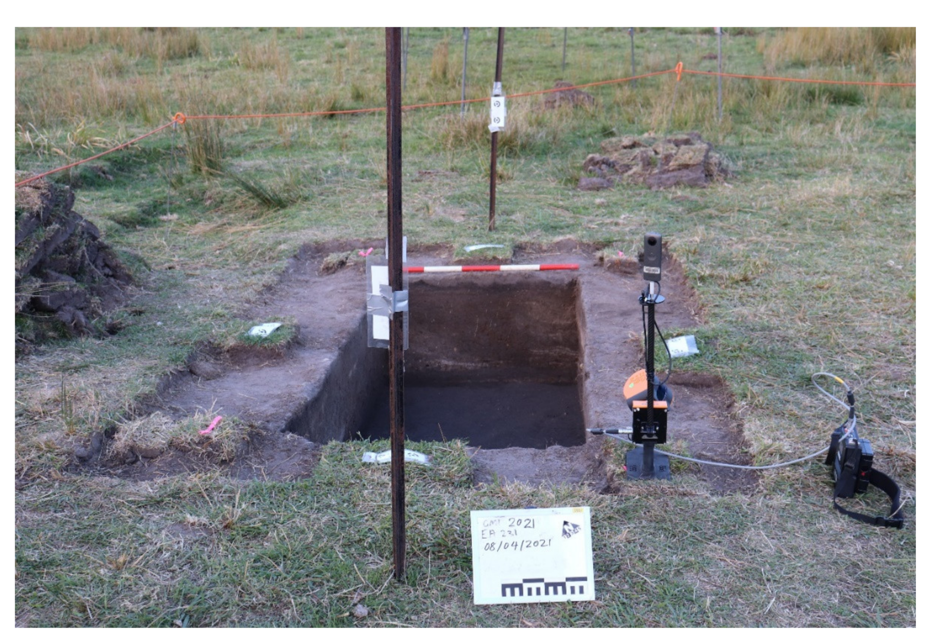
The excavation of EA231 began with de-turfing of the trench, with an extra ca. 25 cm on each side de-turfed to create a stable edge for the alignment of points (
Figure 3). This was necessary, as earlier tests of the equipment indicated that overhanging grass adversely affects model alignment. Below, we outline each of the three methods (TS; PG; SLAM) used to acquire and process the 3D data. Each method was repeated for the eight primary deposits in the trench, and surface areas and volumes were calculated.
5.1. Total Station
The traditional method of recording excavation data during the Ahuahu Archaeological Project is with a total station [
61]. For the excavation of EA231, we used a Trimble S7 Robotic Total Station (Sunnyvale, CA, USA) to record the locations of artefacts, outlines of samples and deposits, and surfaces (of deposits and features). Surfaces were recorded over a triangular grid pattern with points no more than 25 cm apart. When areas with more variable topography were encountered, such as for a feature, this resolution was increased. Raw total station points were processed through the software Trimble Business Center v5.50 (Trimble, Sunnyvale, CA, USA) and exported as ESRI point shapefiles constituting point clouds.
5.2. Photogrammetry
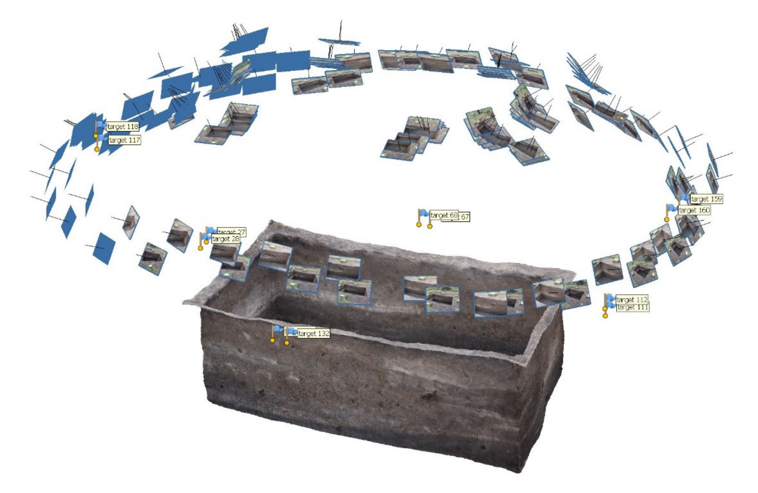
A Canon EOS 800D (Ota City, Tokyo, Japan) camera with a Canon Zoom Lens EF-S 18–55 mm was used to take photographs for PG. The focal length was set at 18 mm for most passes across a trench, but may have been increased for some rotations due to logistical constraints of photographing the interior of the trench. Approximately 100–250 photographs were taken per model. The general approach was to take photos every 20 degrees around the 1x2m trench, equivalent to approximately a small step. A series of top-down photographs were also taken across the trench, which would result in a general model, and to which photographs of specific features that may require more detail could be applied (
Figure 4). Targets were printed from Agisoft Metashape 1.7.2. [
62], laminated, and placed around the trench in the middle of each edge. In addition, two metal “Y” fence posts were put into the ground at two opposing ends of the trench with several targets attached (
Figure 3). The use of 12 targets was necessary for redundancy and georectification. The center of the targets on the ground were recorded with a total station, whereas the targets on the poles were only used to aid in the alignment of the photos and between models. All targets were left in place for the course of the excavation.
Agisoft Metashape 1.7.2. [
62] was used to create the photogrammetric models. Photos were aligned at the highest accuracy to create a sparse set of tie points. The tie points were processed with variables, reprojection error of 0.5 px, reconstruction uncertainty of 15 px, image count of 2, and projection accuracy of 2.5 px. These variables were applied to all deposits except for the turf (Layer 1), where a reconstruction uncertainty of 50 was required to have enough points to construct a dense cloud. The dense cloud for all deposits was constructed at ultra-high quality as was the resulting 3D model, with the latter limited to a face count of 500,000.
5.3. SLAM
We used a GeoSLAM Zeb Horizon (Nottingham, United Kingdom) to capture SLAM TLS data (
Figure 3). Initial tests incorporated four base points at the top corners of the trench; however, this was found to be insufficient to record the interior of the trench. A fifth base point was added to the interior of the trench, which allowed for capture of the depth and the walls. Each of the base points outside the trench was recorded with TS for georectification. These data were processed in the software GeoSLAM Hub 3.5 and GeoSLAM Draw 3.2 R2 (GeoSLAM Inc., Sterling, VA, USA), which allowed for the georeferencing of the base points and alignment of the scans.
The SLAM data contained a high number of points, which made it difficult to create surfaces and define volumes, as the irregular shape of the trench caused uncertainty in the alignment. To mitigate this, CloudCompare 2.11.2 and the proprietary software Geomagic Wrap 2021 were used to clean the point cloud. Outlying points were manually removed to the general shape of the trench, before applying the “Reduce Noise” tool, which gradually removes outlying points. This was done until a surface was achieved in the point cloud. The resulting point cloud was then meshed, normals recalculated, and the volume calculated.
7. Results
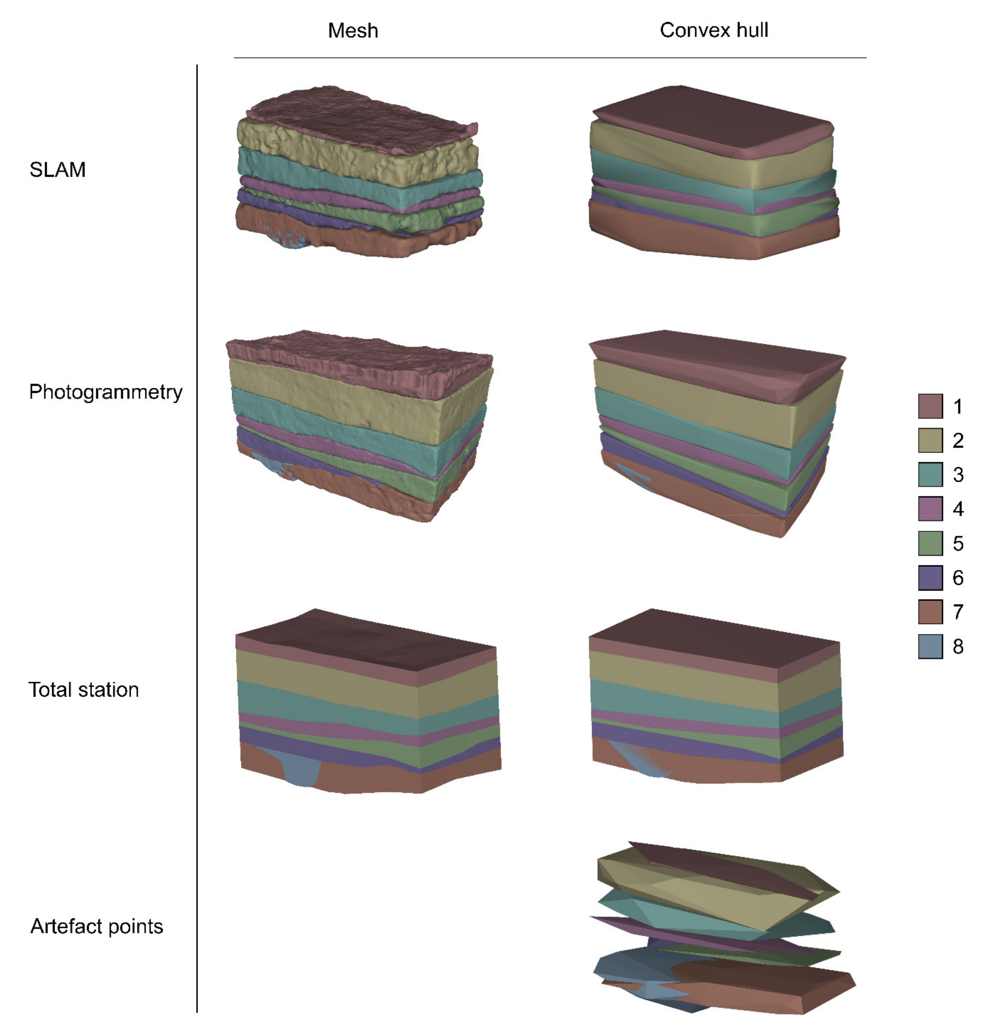
Examination of the 3D representations of the deposits in the trench shows considerable variability in the models created with TS, PG, and SLAM data (
Figure 5). The comparative analysis suggests that the SLAM technology is not well suited towards irregular, relatively small shapes, particularly within a natural environment such as the sand dune swale at Waitetoke without regular surfaces such as those found on buildings and some rock formations. The point clouds generated from the device and associated software had multiple vertical and horizontal “layers” of points within which were several indistinguishable surfaces, as the algorithm could not identify “features” to align the data to. Cleaning was attempted in CloudCompare but noise-reducing filters were again unable to create a surface for each scan. Eventually, the software Geomagic was used to average points to make a single surface for the triangulated mesh, which was used in further processing. As shown in
Figure 5, this mesh is not as smooth as the PG model and has much more surface variation than the PG model, but this variation does not represent the actual surfaces of the deposits. The TS data represented the maximum extents of the excavation of a layer on the x and y axes. Compared to the PG and SLAM models, however, the surface data were of a lower resolution as a result of the way it was collected and, therefore, shows less detail.
The convex hull models created from the point clouds of the three different methods look similar to each other, with the total station model looking the most complete as the points used represent the maximum extent of the excavation. The convex hull created from the artefact point cloud is the least accurate representation of the deposit. Those models of deposits are based on the artifacts contained within the deposit, with artifacts very rarely located at the maximum extent of deposits. In general, compared to the triangulated meshes of the point clouds of the three acquisition methods (TS, PG, SLAM), the convex hulls lose the internal variation of surfaces, as many of these form concave shapes.
7.1. Surface Comparison
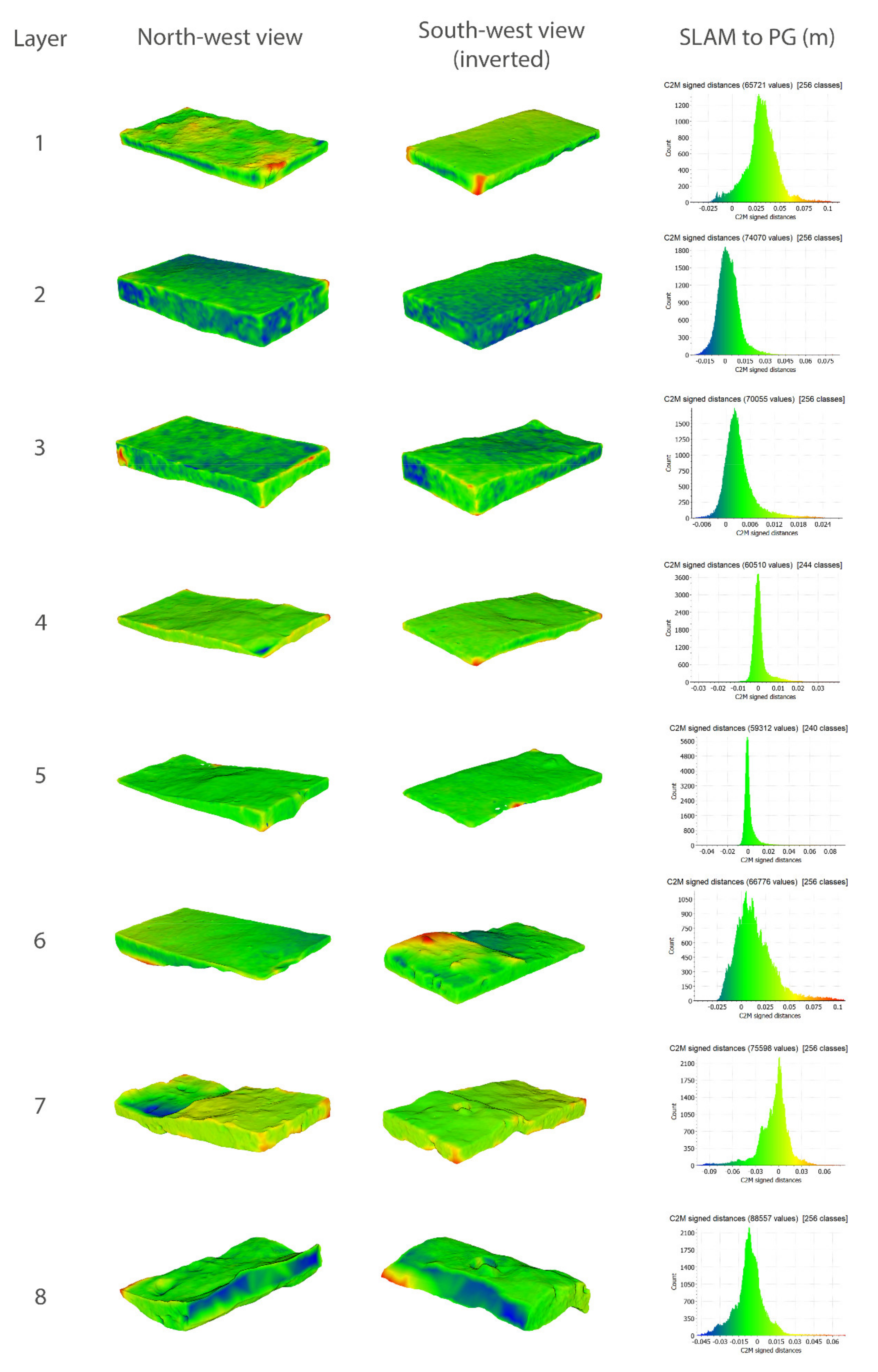
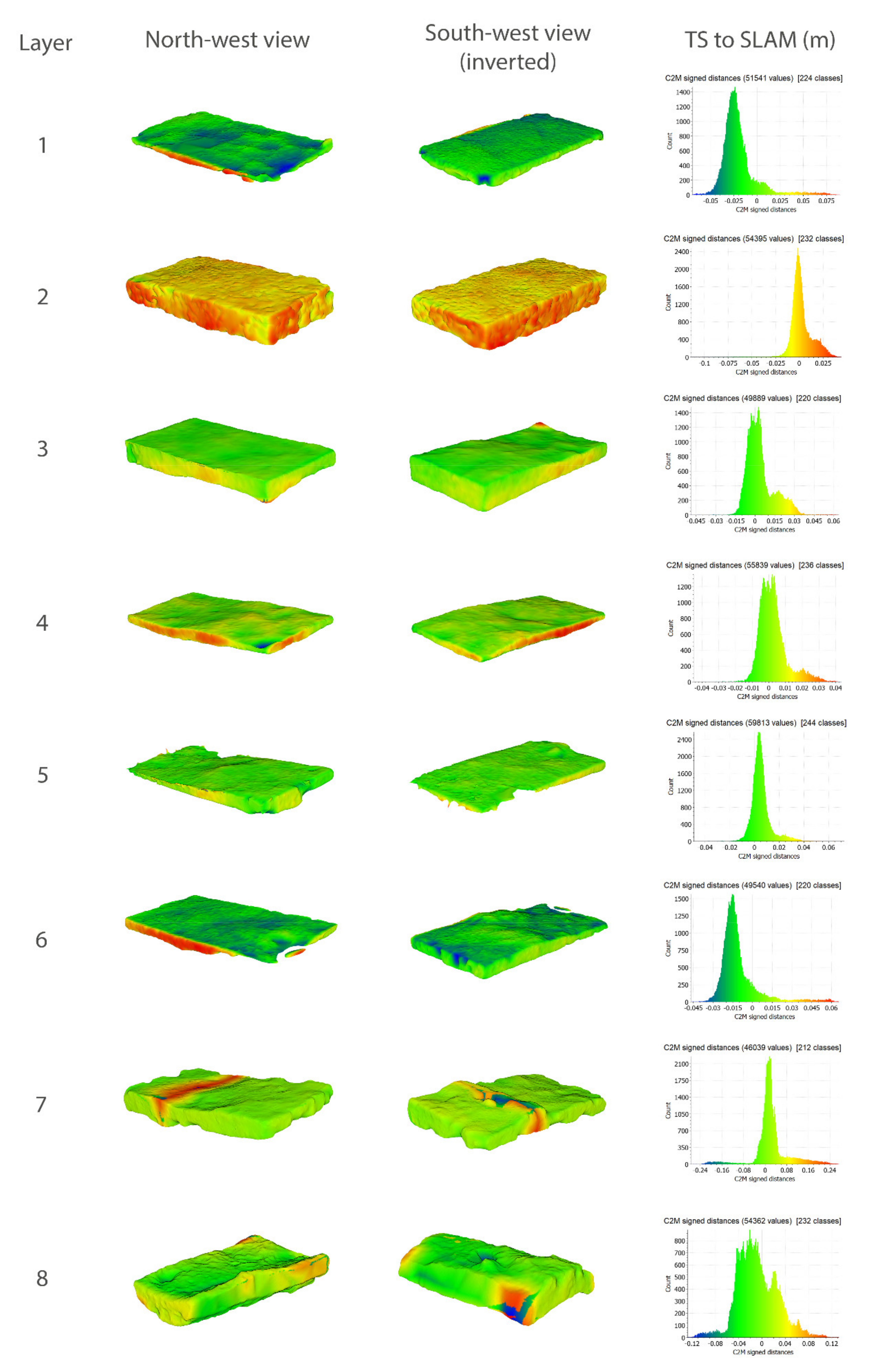
To evaluate the difference between the triangulated meshed surfaces of the three methods the distances between the meshes of the deposits created with the three methods were measured in CloudCompare. In
Figure 6 and
Figure 7, the PG model of the deposits were used as the base in the comparisons for the SLAM and TS models. There are some discrepancies between the SLAM and PG models, particularly around the edges, corners, and sides of the models (
Figure 6). This is also the case for thinner areas where the averaging used to clean the SLAM point cloud resulted in overlap between the top and bottom surfaces. Layer 5 in
Figure 6 depicts this on the inverse view in red; however, there are also holes in the PG model demonstrating that this area was so thin that it too had an issue creating separate deposits, albeit to a lesser degree.
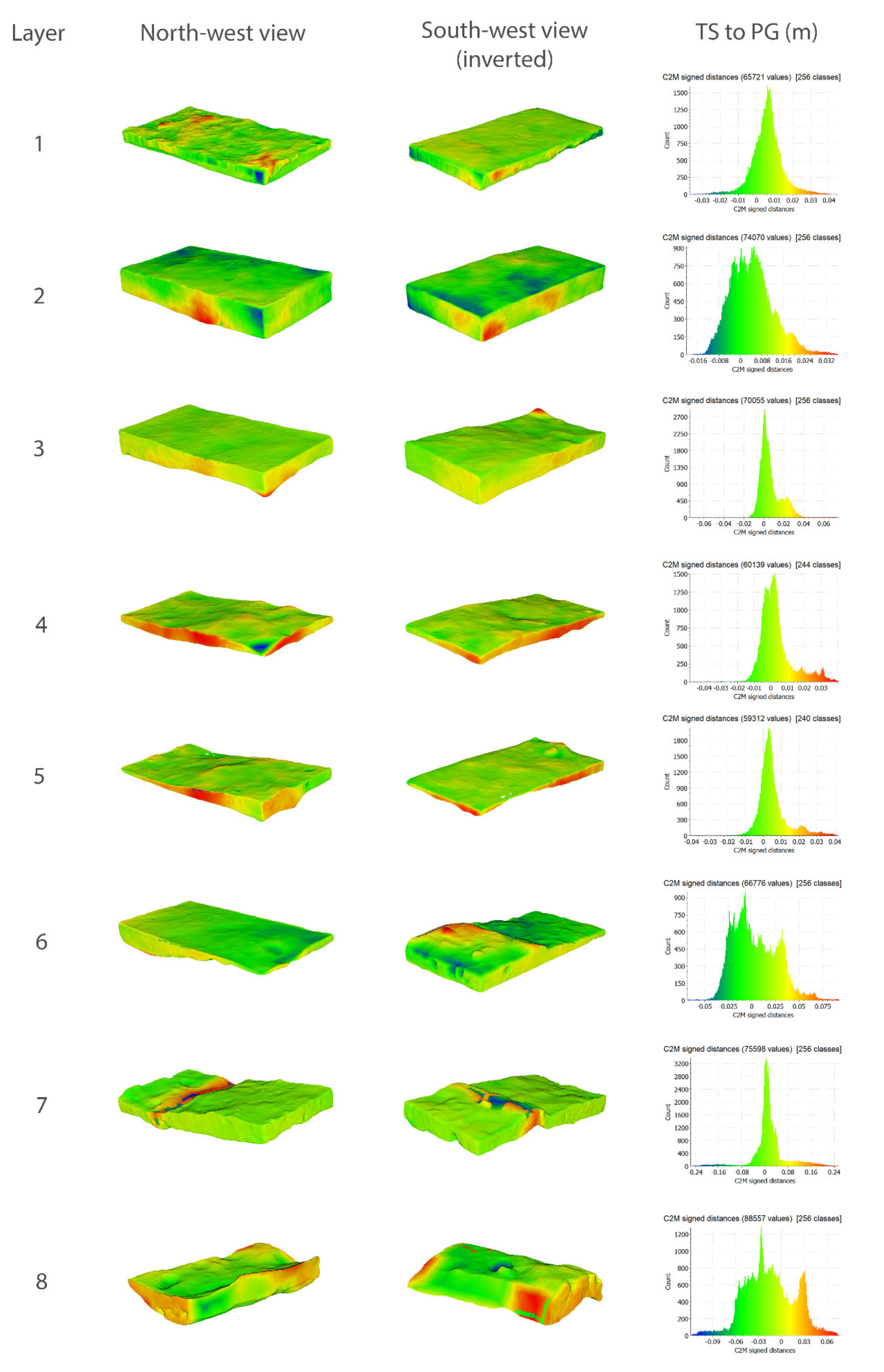
Unsurprisingly, there are also discrepancies between the TS and PG models, particularly considering smaller details. The walls on the TS models were flat, and therefore, differences are shown to the PG model that was not. Layer 1 represented in
Figure 7 also shows where smaller differences are apparent such as the grass present on the surface (shown as red), which was captured by PG but because of the resolution was not captured by TS. Comparison of the TS and SLAM models shows similar results to that of the TS and PG (
Figure 8). The walls are still a source of difference because of the basic lack of data for them in the TS models. Layer 2 in
Figure 8 shows a high level of discrepancy between the TS to the SLAM model, and the lack of agreement between the two demonstrates the inability of the SLAM data to identify a surface in this case.
Table 2 reports estimates of surface area in m
2 by deposit for each method across modelling techniques. Paired
t-tests or Wilcoxon signed-ranks tests were used to statistically assess pair-wise differences in estimated surface areas within deposits for three methods (SLAM, PG, or TS) across the two modelling techniques, triangulated mesh and convex hull. The test used was based on the results of a Shapiro–Wilk test for normality (
Table 3). The results in the first section of
Table 3 indicate that there are no significant differences in the surface areas of deposits between the meshed SLAM, PG, and TS models when each mesh model is compared with another mesh model. Counter to this are the visual differences between the triangulated meshes for PG and SLAM data discussed above (
Figure 6), which suggests that the differences are largely visual. The results in the second section of
Table 3 indicate that within each method, surface areas estimated using convex hulls are consistently greater than those estimated using triangulated mesh. This suggests that those convex hull models are over-representing the true extent of the deposits. Results in the third section of the table indicate that there are significant differences in the surface areas of deposits between the convex hull SLAM, PG, and TS models when each convex hull model is compared with another convex hull model. It seems that the over estimation of surface areas of the convex hull models of deposits of the individual methods is enough to establish differences between the three methods in a comparison of the convex hull models by method.
To evaluate the surface estimates of the three models simultaneously within each modelling technique repeated measures ANOVA were run. The first set compared differences in volume or surface areas estimated from SLAM, PG and TS methods modeled using triangulated mesh. The second, assessed differences from these methods model using convex hulls. The results of these repeated measures ANOVA indicated that the residuals were not normally distributed, consequently we used Friedman test. The Friedman test of rank-order differences in surface area estimates per deposit for the three methods modeled using triangulated mesh shows that differences among methods across deposits are not consistent enough to be judged statistically significant (Friedman test statistic = 5.24, Kendall coefficient of concordance = 0.328, p = 0.072). The same Friedman test comparison of surface areas modeled using convex hulls does indicate a statistically significant consistency in pattern of differences across the three methods (Friedman test statistic = 9.0, Kendall coefficient of concordance = 0.562, p = 0.011). This result can be attributed to the over-representation of surface areas when hull models are made in relation to triangulated mesh models.
7.2. Volume Comparison
Table 4 reports estimates of volume in m
3 by deposit with each method and modelling technique. Paired
t-tests or Wilcoxon signed-ranks tests assessed pair-wise differences in estimated volumes within deposits for each method (SLAM, PG, or TS) across the two modelling techniques. The results in the first section of
Table 5 indicate that there are no significant differences in the volumes of deposits between the meshed SLAM, PG, and TS models when each mesh model is compared with another mesh model. The results in the second section of
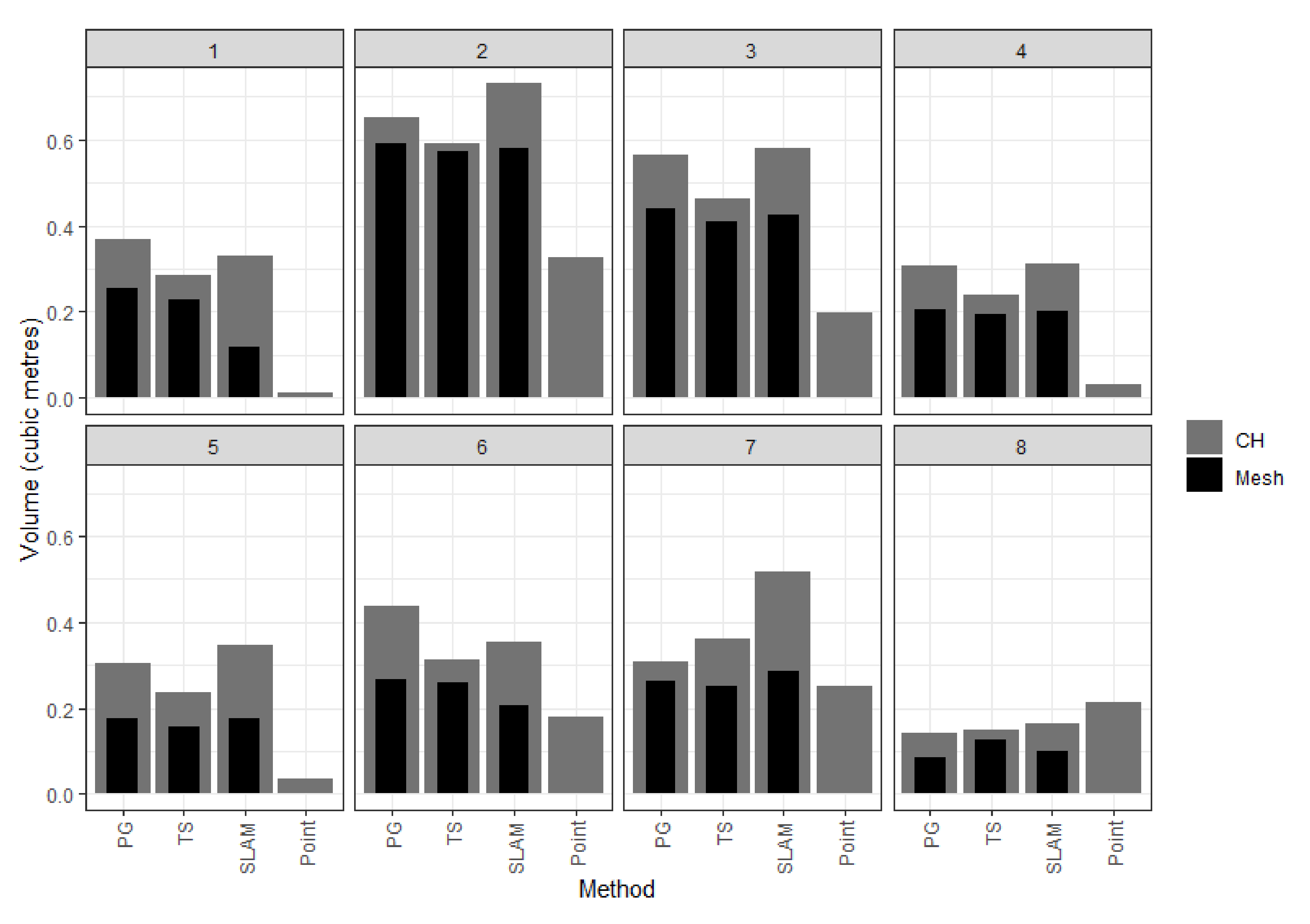
Table 5 indicate that within each method, volumes estimated using convex hulls are consistently greater than those estimated using triangulated mesh. Convex hull calculations tend to over-represent the volume of the mesh as concavities are ignored (
Figure 9). While the extent of the over-representation varies, in general SLAM convex hulls over-represent volume the most, followed by PG. The least discrepancy is amongst the TS volume reconstructions, likely because of the reduced resolution (number of points) used in the meshing process. The difference in volume between meshes and convex hulls is especially apparent in the calculation of layer 7 (
Table 4). The results in the third section of
Table 5 indicate that there are significant differences in the volumes of deposits between the convex hull SLAM, PG, and TS models when each convex hull model is compared with another convex hull model. The increased surface variation in the SLAM and PG meshes is a likely cause of this, as the TS has less variation as a product of the lower number of points used in the convex hull calculation.
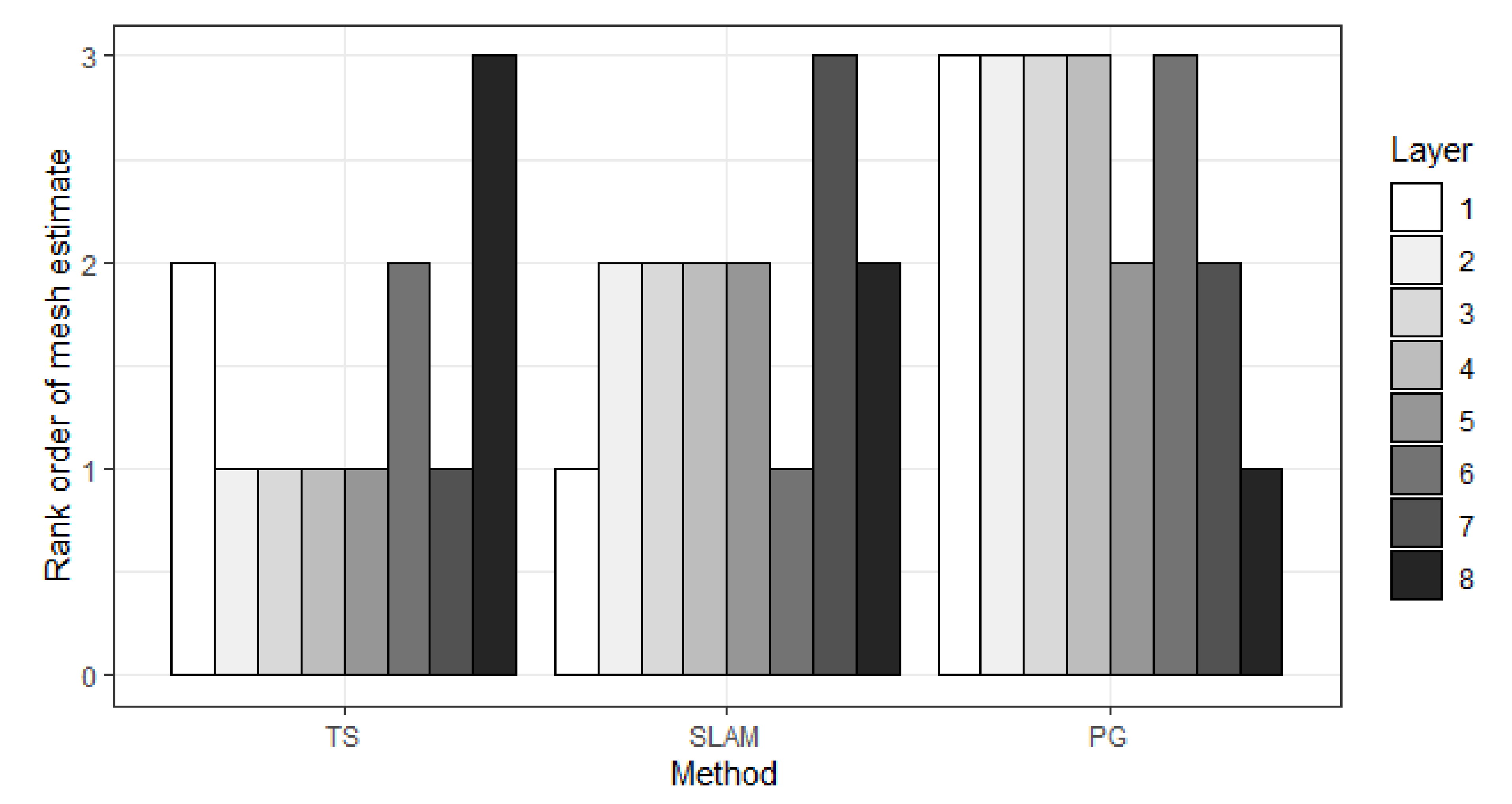
The Friedman test of differences in volume estimates per deposit confirm these results. The result for the three methods modeled using triangulated mesh indicates that estimates are not statistically distinct (Friedman test statistic = 5.25, Kendall coefficient of concordance = 0.328,
p = 0.072). However, a visual inspection of the rank order of deposit volumes of each method shows indicative patterning (
Figure 10). The TS estimates of deposit volumes are generally lower than the SLAM estimates, which are generally lower than the PG estimates. The SLAM and PG point clouds have higher resolution point clouds than the TS point clouds and, therefore, record more surface variability. This can result in an increase in volume, as small variations are recorded that the TS does not record. As noted, this variability, however, is not statistically distinct. However, Friedman test results using convex hulls show a consistent pattern of differences in volume estimates of the three methods (Friedman test statistic = 9.0, Kendall coefficient of concordance = 0.562,
p = 0.011), again the result of overrepresentation of volume in convex hull models.
7.3. Artefact Densities
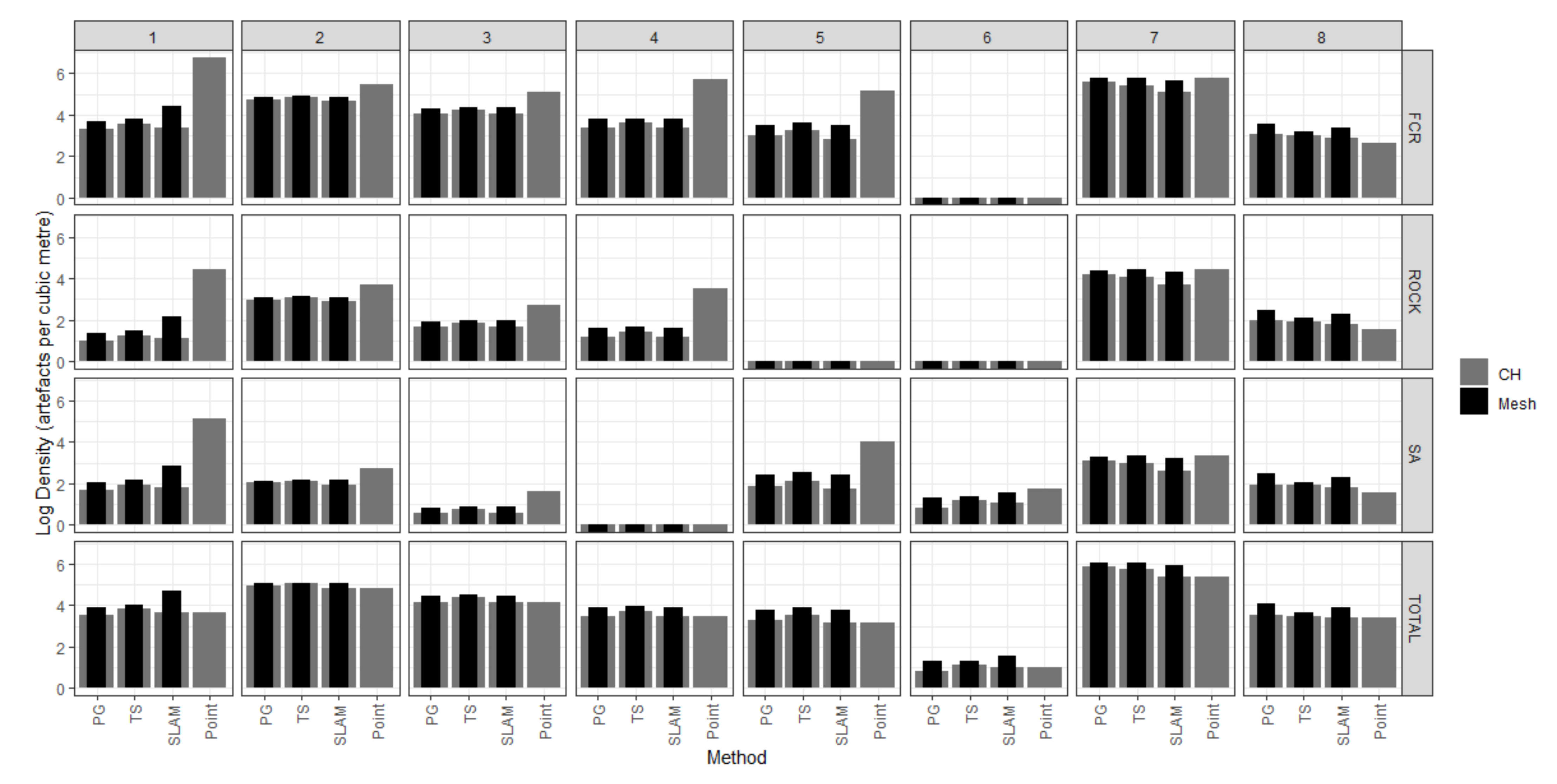
The deposits of EA231 contained vastly different amounts of artifactual material (
Figure 11,
Table 6). Without considering the volume of deposits, it would be easy to conclude that layers 2 and 7 of EA231 contained large, almost equal, amounts of material, with layer 4 containing much less material. This would be an obvious misunderstanding of the spatial patterning of artifactual material, as it is necessary to calculate the volume of deposits to establish artefact densities to identify spatial patterning within EA231. These artefact densities were calculated using the deposit volume estimates of the meshes and convex hulls of the three different acquisition methods. This simplistic analysis of the 3D data in relation to artifact distributions demonstrates that layer 7 has more than double the artefact density of layer 2, and layer 4 with much lower artifact frequencies than layer 2 has densities of almost a third of that deposit.
The more useful aspect of our analysis is not the simplistic calculation of densities from EA231, rather the quantification of differences of artefact densities produced by the volume estimates of the three different acquisition methods. As shown by the statistical tests discussed above, the mesh volume estimates of the three methods do not differ significantly. The variation in artefact densities in those deposits reflects this. The artifact densities associated with the convex hull estimates of volume show more variability, as those models accentuate the volume differences of a deposit. The artefact densities calculated using the volume estimates of the artefact point convex hulls further distort patterning, as they greatly under-represent the artefact densities because those models greatly over-represent the volumes of deposits.
8. Discussion
One reason for recording deposits during excavation is to enable stratigraphic analysis. In practice, recording deposits is complex, as where a deposit begins and ends can be difficult to determine. In some cases, a change in deposit is only noticed retrospectively either when the next deposit is being excavated or at the end of the excavation when profiles are drawn. The profile of EA231 (
Figure 2) demonstrates some of the issues, as some deposits in this profile (which are shown unnumbered in that profile) were only identified during final recording and were not recorded with TS, PG, or SLAM during excavation. This is unavoidable, as it is difficult, if not impossible, to identify all deposits during the excavation process. This does, however, call into question the utility of creating 3D representations of excavated deposits. Deposits represent the process of excavation, the decisions that were made, and the places where excavators identified differences in the matrix significant enough to meet their criterion for defining a new deposit. Analytically and for archaeological investigation, this means that the volumes of deposits recorded during excavation must be carefully considered with other archaeological data such as stratigraphic drawings, artefact densities, and data from related excavations, before their bounds and densities are accepted. These ambiguities surrounding deposits are issues that must be dealt with regardless of which data acquisition method (e.g., TS, PG, and SLAM) is used. However, as the resolution at which TS is recorded is lower than PG and SLAM, using TS does make some decisions easier and provide the ability to “reconstruct” or revise the extents of previously excavated deposits.
The various methods used to calculate volumes of deposits affect the definition and essential qualities of deposits. The mesh is a triangulation of the points that represent the exterior of the volume, whereas the convex hull represents the smallest convex surface area around a set of points. A convex hull will only mimic a triangulated mesh when there is little concave variation in the surface of the mesh. This is obviously ill-suited for most archaeological data, as surface variation can occur as both convex and concave shapes. Layer 7 exemplifies this as a concave shape that is represented by its base means that a larger area is represented by the volume than actually exists (
Figure 5). As the statistical tests above showed, while they may not be as pronounced as in layer 7, the convex hull models over-represent the volumes of the deposits compared to the triangulated meshes.
Our statistical analysis indicates that there are no significant differences between the triangulated mesh surface areas and volumes of deposits created from the TS, PG, and SLAM data. There does appear to be some patterning in the data that suggests that TS mesh volume estimates of deposits are smaller than SLAM meshes of those deposits, with PG volumes being largest, but that patterning is neither consistent nor statistically significant. Larger volumes will of course result in the calculation of lower artifact densities, while smaller volumes result in higher densities.
The statistical result that there are no significant differences between the surface area or volume estimates produced by TS, PG, and SLAM triangular meshes and data acquisition methods suggests that other factors should be considered when deciding which method to use.
8.1. Time
The amount of time to implement the TS, PG, or SLAM method varies both for in-field recording and subsequent processing. While measurements were not taken on the exact time spent during the acquisition and processing of data for each recording method, some general observations can be made. Overall, the in-field recording of TS data is the quickest, with SLAM and PG taking about the same time. Each method can vary depending on the proficiency of the operator, the weather on the day, and the complexity of the subject. A deposit with a more complex shape, such as layers 7 or 8, will take more time than a relatively simple deposit such as layer 2. With SLAM, the initial setup of bases that were recorded with a total station were used over the course of the excavation, and so it was only the actual scanning that needed to occur, as was the case with PG and the attributed targets. What was required for both of those methods was also that the area be cleared of excavation equipment and people, more so than would occur during the standard photography of a unit. TS recording does require areas to be generally free of excavators, but it is not necessary to remove all excavation gear. That TS recording was more seamless in terms of workflow, as the total station is already part of the provenancing of artifacts and other materials during the excavation. However, TS recording a more complex shaped volume such as layer 8 will require more points to capture its shape and, therefore, take longer than the use of PG or SLAM.
The amount of time to process the data once they have been recorded also varies between the three methods. The SLAM data arguably took the longest active processing, that being where an operator’s attention was required to align and clean the data before producing a point cloud of a deposit. PG took the most computer processing time but required less from the operator in that it could mostly be automated and processed in batches. Once the meshes were created, these then needed to be edited into volumes as outlined above, which required active researcher attention. TS data processing was mostly manually done by an operator, but the points used for each deposit were relatively few and took little time to isolate and triangulate into a volume.
8.2. Cost
There are differences in the monetary costs of each method. While the price and availability of different technologies varies from region to region, general trends can be noted. TS range in price but usually cost in the tens of thousands of dollars, and for efficient data capture on the scale required for surface reconstructions, a robotic TS is required, which are generally more expensive. A TS can, however, be used with minimal training and usually comes with the software required to process the raw data. PG requires a camera and ideally a tripod to capture the data and PG software, which can be open-source or proprietary. While cameras can vary dramatically in cost, a camera of sufficient quality is relatively inexpensive. PG is the most cost-effective method of these three and can be implemented and processed successfully with minimal training. By comparison, SLAM is more expensive, as the machinery costs tens of thousands of dollars, but also requires proprietary software to process the data. There is some open-source software such as CloudCompare, which can be used for data processing, but often obtaining data to these requires outputting data from the machine through a proprietary software. As with the other methods, SLAM can be learnt relatively quickly.
9. Conclusions
The application of 3D recording to archaeological excavations will continue to become commonplace in archaeological inquiry. This will result in the modification and revising of workflows to account for these methods, but the extent to which this needs to occur is important to consider. Based on the above, it was found that obtaining PG and SLAM data in addition to TS data for each deposit was largely redundant if deposit volumes were the goal. Volumes created from TS data create a statistically similar volume in less time, both in the field and during the processing of that data in the lab. PG volumes, however, provide what can be considered as the most “real” visualization.
These conclusions are based on the current state of technology, both in terms of the instruments required for TS, PG, and SLAM data acquisition and the processing of that data into 3D surface and volumetric entities. We suspect that with future developments, the advantages and disadvantages of the three methods will shift, and indeed, the methods will be replaced by new approaches. Currently, for recording purposes, a PG or SLAM model could be made of the end of an excavation, of which the TS volumes could then be enclosed within for visualization. This also allows for the representation of any deposits identified at the end of excavation that may have been missed. However, their surface variability within the trench will not be possible to reconstruct.
There may be a perceived benefit of recording every layer to a high degree of detail in that is creates a record of the excavation. However, the analytical benefit of this must be weighed against the time to complete it. It must also be carefully considered what is being recorded. The deposits represented, while broadly representative of the extents of the archaeological deposits they were recorded as, are equally if not more so representative of the decisions that went into excavation and recording.


 ,
, 


