1. Introduction
After decades of research, the chaotic signal is experiencing rapid development in many fields, such as engineering and science. In a variety of applications, chaotic signals have been observed, including mechanics, electronics, chemistry, and acoustics. Since it owns many of the features that distinguish it, such as the chaotic signal random-in-time involvement with no periodicity, but rather the signal energy is distributed across all ranges of frequency and a chaotic signal can be generated from simple chaotic deterministic systems, the noise-like and complex behavior of a chaotic signal could have advantages in various fields of practical applications, such as being used in radar systems [
1,
2,
3]. This feature of the chaotic signal makes the radar signal simple to implement, less sensitive to jamming or interference, and easy to process.
Typically, chaotic signal (CS) is characterized as a deterministic broadband signal, has a structure, and the maximum Lyapunov exponent is greater than zero; meanwhile the noise is expressed as a random and non-deterministic signal [
3]. As CS has distinct characteristics of unsystematic phase variation and broadband of power spectrum, so chaos radars can easily offer the key characteristics:
Chaotic signal using simple and inexpensive deterministic systems.
CS has featureless low-probability of intercept/low probability of detection (LPI/LPD) characteristics, and therefore it is hidden or invisible signal.
CS is inherently anti-jamming signal and interference resistant.
CS is spectrally very efficient and can share spectral bands without any mutual interference. Then chaotic radar may utilize coherent signal processing schemes either by matched filter or correlation in order to reduce the noise in the echo signal and detect the target successfully.
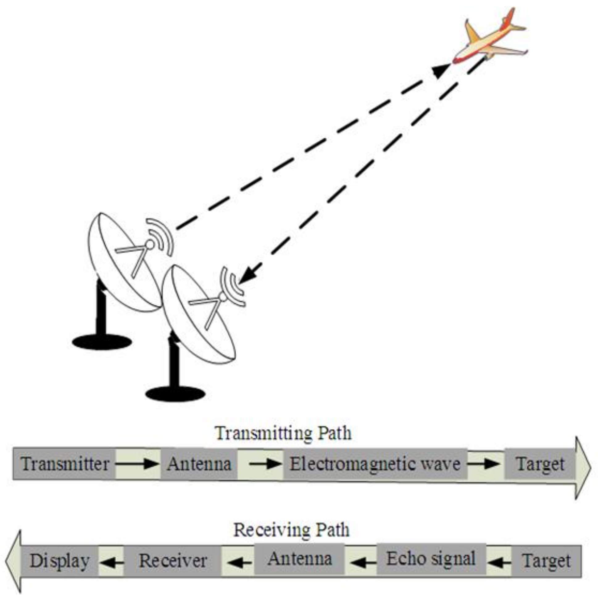
In general, in radar systems, there are a number of transmitter/receiver (antenna) nodes that are designed to make the system operate either as monostatic, bistatic, or multistatic radar. Each radar system depends on the type of waveform, whether continuous or non-continuous (i.e., pulse wave) [
2]. The radar is called monostatic radar if the transmitter and receiver are placed in the same place; otherwise, the radar is a bistatic or multistatic type if both transmitter and receiver(s) are separately located over a distance [
4].
Figure 1 depicts the three types of radar systems.
However, the major drawback in these passive bistatic radars mainly suffers from the lack of control on the transmitting waveform. Meanwhile, the conventional monostatic defense radars have a shortage in detecting low radar cross-section (L-RCS) targets.
Figure 2 illustrates the fundamental operation of mono-static radar systems. In fact, the RCS metric is the crucial measure that defines the reflectivity of the target measure; thus, a larger RCS means easier target detection because the RCS of any target depends on the radar’s transmitted frequency. Thus, the long-wave radars (below HF) have more precision, with large RCS compared to HF, VHF, and UHF radars. More details are presented in [
2,
5,
6]. However, most conventional radars are basically designed to operate on the microwave frequency band between 300 MHz (1 m) and 300 GHz (1 mm). On the other hand, several chaos radar systems have been designed and implemented for various secure communications [
7,
8,
9,
10]; they may employ coherent signal processing schemes either by matched filter or correlation to reduce the noise and eventually obtain the highest improvement in Signal-to-Noise Ratio (SNR) [
7,
11]. Another issue in chaotic based radar systems (CBRS) is choosing the type of chaos synchronization between the transmitter and the receiver nodes. Conversely, traditional synchronization schemes such as Phase-Locked Loop (PLL) can be used in chaotic radars [
4]. In fact, there are many studies on complete synchronization and feedback control [
7,
8] in a radar system, but the limitation is raised due to its sensitivity to noise, and any tiny amounts of additive noise to the (echo) signal can degrade the synchronization quality, and the chaotic signals may not be synchronized [
11].
Moreover, some CBRS systems have been widely studied, either with no modulation, such as pulse compression, or within a variety of modulation methods, such as continuous AM/FM/PM modulation where many CBRSs are utilized in microwave and UWB and laser applications [
4,
12,
13]. One example was devoted to a microwave chaos signal practically generated through the Colpitts oscillator and directly transmitted through a wide-band antenna without modulation [
7,
8]. In this paper, therefore, the key issue is how to design a robust chaotic radar system that can provide a complete- or quasi-synchronization in order to successfully recover the echo signal and then detect the target. To achieve this goal, we present a new robust indirect mono-static FM-based chaos radar using a time-delayed chaotic system under various levels of noise over the wireless channel. The design is simple and it does not need to use the complete self-synchronization or any complex projective synchronization schemes.
The following is a breakdown of the paper’s structure:
Section 2 introduces an overview of the frequency band design of radar systems and stealth counters.
Section 3 explains the chaos radar challenges and the main contribution in this study.
Section 4 addresses some related works on chaotic radars. The dynamical analysis of the mathematical model of the first-order time-delay chaotic system, as well as its dynamical properties such as the phase portrait chaotic attractor, equilibrium points, Nyquist plot, and bifurcation diagram, are presented in
Section 5.
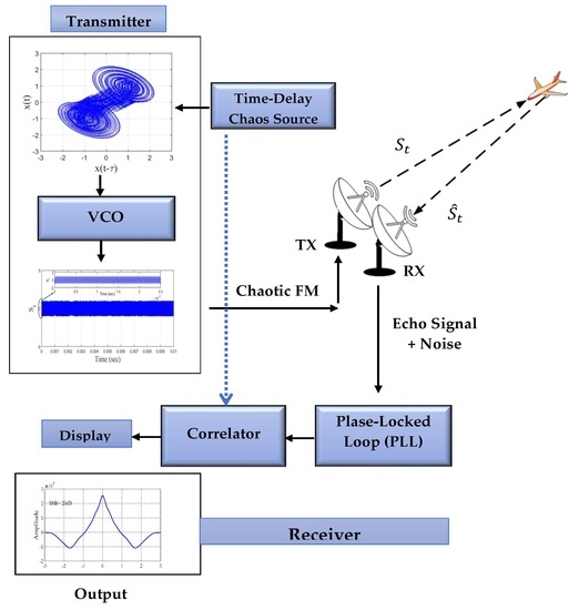
Section 6 describes the chaotic signal based on FM modulation and how to modulate the chaotic signal with the voltage control oscillator (VCO) to generate continuous FM signals and then recover the reference signal with the PLL.
Section 7 explains the comparative performance with the existing chaotic radars. Finally,
Section 8 summarizes the conclusions and perspectives of this paper.
2. Radar Systems and Stealth Counter: Overview
Obviously, the design of radar systems mainly depends on the desired band and the purpose of applications in civil or military communications. The usual microwave radars are often used from 2 GHz up to 40 GHz, and among these are Ultra-Wide Band (UWB) radars. Meanwhile, the low-frequency radars frequently use lower bands less than 1 GHz, such as L-band (1–2 GHz), UHF, VHF, and HF bands. Other types are called LiDAR (Light Detection and Ranging) or Laser Radars. These radars use visible, ultraviolet, or near-infrared radiation to detect targets. Ultrasound and sonar systems, on the other hand, use acoustics (audio and speech) waveforms. Specifically, the relatively large antennas often use frequencies within a bandwidth of 270 MHz (as VHF (30–300) MHz) or 700 MHz (as UHF (300 MHz–1 GHz)) to achieve narrow beams that may experience interference as they propagate through the ionosphere.
Small antennas, on the contrary, may be employed with weather radars in the S (2–4) GHz, C (4–8) GHz, X (8–12) GHz, K
u (12–18) GHz, and K (18–27) GHz bands to produce narrow beams and good range resolution. Skywave and Ground wave radars are the two forms of Over-the-Horizon (OTH) radars, respectively. Ground-wave radars can identify targets at very long range, often between (100 and 1000) km. They also operate at low frequencies (below 3 MHz), and therefore they suffer from diffraction due to the surface of the earth. Longwave bands in HF band (3–30) MHz employ Skywave (shortwave), where the short wave depends on the ionosphere [
2,
4,
5,
6,
7,
8,
9,
14].
On the other hand, the stealth counter has become an important topic in recent years to minimize the effectiveness of Radar Cross-Section (RCS) measures, and this requirement remains an open challenge in radar system design. Stealth is used to prevent detection systems under work by utilizing the electromagnetic spectrum, such as making the RCS small or through changing the shape of the aircraft, by using Radar Absorbing Material (RAM), or by utilizing the plasma which attenuates the radar energy. However, at high radar frequency, the attenuation effect of the plasma becomes greatest, while at VLFs it may be reflected by the plasma. Blessedly, most radar systems that aircraft are required to defend against operate in the X and K
u frequency bands. However, the design aim of the Low Observable (L.O.) or stealthy aircraft in the X and K
u bands is to reduce radar emission energy. At lower frequency bands, the RCS of L.O. aircraft must be increased, and the RAM use for the target is not so efficient in these bands. Therefore, this results in a serious interest in working on anti-stealth capabilities in radar systems [
5,
6].
Notably, during the Kosovo war in 1999, for example, the old VHF (also known as low frequency) radar was utilized to shoot down an F-117 Nighthawk by Serb forces [
8,
9]. Since 2013, several new radars for military and secure communications have been developed, including multitoned harmonic non-linear radar, US Navy Re-Locatable Over-the-Horizon Radar (ROTH), and OTH radar. Regardless of the target’s altitude, they can identify stealthy and small targets at very long ranges. Although such radars have disadvantages, such as massive antennas, immobility, and a large quantity of clutter, they are nonetheless highly effective against stealth ships and stealth aircraft when deployed on the ground [
9,
10,
14].
Additionally, the radar systems have also been linked with modern infrared for search and tracking (IRST) systems to provide anti-stealth capabilities in secure communications and the military. The IRST system actively scans the airspace for heat signatures, transmitting its IR emission, and passively detects and tracks the target based on IR emission, allowing the crew to attack without warning the target (i.e., first look then shoot). The IRST21 sensor in the F-14D Tomcat and the IRST in the super Hornet are two examples of current systems that are now in low production and could be operational by 2018, as shown in
Figure 3 [
6,
15].
3. Chaos Radar Challenges
There are some challenges and problems facing the chaos radar systems that can be summarized as follows:
The key challenge is to build an easy, low cost, and more secure chaotic radar system, but this may result a complex behavior. The challenge for chaotic waveforms is whether these properties are adequate to provide unique and operant radar implementations.
The parameters mismatch in chaotic systems is still unavoidable in real situations of chaos synchronization. If the drive-response systems are not identical and there is a parameters mismatch, the synchronization error does not definitely converge to zero or it may lead to small fluctuations about zero; this is called quasi-synchronization or asymptotic synchronization [
16]. Otherwise, loss of synchronization may occur in case of large parameters mismatch. Therefore, to design accurate synchronization with reasonable precision between the transmitter and the receiver, it is necessary to consider the role of parameters mismatch in the synchronization process.
Moreover, the relationship between chaos synchronization in time-delayed feedback systems and parameters mismatch is also another quite complex issue.
To the best of our knowledge, some studies [
17,
18] are only concerned with the coupled systems without time delay in the presence of parameters mismatch. Other significant reports have also been devoted on the adaptive-observer synchronization schemes to solve this problem using different time-delay chaotic systems [
2,
3,
4,
5,
6,
7,
8,
9,
10,
11,
12,
13,
14,
15,
16,
17,
18,
19]. Among these, Liu et al. [
16], He et al. [
19] and Huang et al. [
20] have discussed some approaches on synchronization of two coupled delayed systems with parameters mismatch under particular certain coupling strength for the delayed Lur’e systems.
Upon these challenges, one of the solutions for the synchronization in the CBSR system is the Voltage-Control-Oscillator (VCO), which can be used for FM modulation in radar applications and by converting the frequencies of a base-band chaotic source system to microwave frequencies. The output frequencies are linearly changed with applied input to VCO and the constant amplitude of the output microwave-signal. The frequency modulation method (FM) describes many characteristics such as the low eventuality of interception or detection in a radar system, the lower effect of jamming or noise, and less interjecting with other channels [
4,
10]. The authors focused on microwave chaos signal practically created by the Colpitts oscillator and directly sent through a wide-band antenna without modulation, since direct (i.e., without modulation) chaotic radar remains a major system in the research field [
3,
7].
Referring to the essential design criteria for a chaotic radar system, the main contributions in this study are summarized as follows:
A new 0.3 GHz mono-static microwave chaotic radar is proposed based on a time-delay to generate and process frequency modulated (FM) waveforms. Tuning the right value for the loop gain (G) is carefully set in the Phase-Locked Loop (PLL) in order to reflect more reliable signal recovery.
The finding indicates that such a radar system can be implemented with no need to complete self-synchronization or complex projective synchronization.
Obtained results reveal the robustness of chaotic monostatic radar under various noise levels in terms of short-time cross-correlation of the transmitted and reconstructed waveforms.
The proposed indirect mon-static chaotic radar system is considered as a state-of-the-art in a secure communication application.
4. Related Work
Synchronization of chaotic systems is an interesting scheme and is studied in many research engineering applications. The first savant studied the synchronization between two identical systems without the same initial condition by Pecora and Carroll (PC) in 1990 [
21]. Several control methods have been devoted to the chaotic signal in order to make the synchronization between two systems (master–slave), such as Ott et al. who, in 1990, first presented the scheme of chaos control [
22], sliding mode control method [
23], adaptive control method [
24], impulsive control method [
25], back-stepping design method [
26], sampled-data feedback method [
27], and other methods for control on synchronization of the chaotic signal [
28]. This method and other methods have been proposed to make different chaotic systems stabilized around the unstable orbit. One example is finite-/fixed-time synchronization of memristor chaotic systems (MCSs), which are addressed via the sliding-mode control method in image encryption applications [
29].
On the other hand, Chandra et al., in [
4], introduced chaos-based frequency modulated (CBFM) waveforms for joint monostatic and bi-static radar-communication systems, and the wideband radar imaging uses short-duration pulses created by chaotic oscillators, with the information contained in the pulses using chaos shift keying (CSK). The information is decoded at the communication receiver, and the transmitted waveform is reconstructed at the bistatic radar receiver, using a self-synchronization technique for chaotic systems, and it is shown that the CBFM waveforms closely track the theoretical Bit-Error Rate (BER) associated with bipolar phase-shift keying using a nonlinear detection approach (BPSK). At the bistatic radar receiver; the same nonlinear detection approach is used to optimize target detection. In both the monostatic and bistatic examples, the ambiguity function resembles a thumbtack ambiguity function with a pseudo-random side lobe distribution. In addition, Al-Suhail et al. [
2] proposed a direct monostatic radar model using a chaotic time-delayed system in the presence of self-synchronization to recover the echo signal for long-wave anti-stealth applications. To overcome the problems encountered in VLF chaos radar design, such as parameters mismatch of chaotic system in chaos synchronization, in this paper, we developed the FM-based chaotic radar system (0.3 GHz). The Phase-Locked Loop (PLL) is used in place of Pecora and Carroll (PC) or an adaptive-observer scheme in order to achieve chaos synchronization and then recover the original signal correctly. The master chaotic signal (source) is transmitted via the VCO to convert the baseband signal to a microwave signal; after that, it is transmitted through a wireless channel with echo delay and under various values of noise levels. Then, the received echo signal is demodulated by the analog Phase-Locked Loop (PLL) to recover the reference signal, and the correlation is used to measure the performance of the proposed mono-static radar system.
5. Design of Time-Delay Chaotic Systems
In this study, chaotic behavior in a dynamical system with a single state variable and a minimum number of elements is addressed in detail using a simple time-delay chaotic system in Lur’e form. The Lur’e system consists of three elements, namely time-delay, an integrator, and non-linearity, respectively, as shown in
Figure 4. The time-delay affects the dynamic of the systems, such as single state time-delay, which makes the system infinite-dimensional, the integrator officiates the system dynamics of a single state, and the non-linearity is a necessary part and is wanted as a major, so chaos is a distinguishing characteristic of nonlinear systems [
30,
31]. Consequently, the dimensionless equation of the Lur’e system can be expressed as follows
where
is the state variable,
,
is a non-linear function,
is the time-delay,
is the scaling factor, and
and
are system parameters. the non-linearity is multiplied by the gain
, whilst the pole of the Miller integrator is
. The Lur’e form in system (1) consists of two parts: the linear part given by
and the feedback nonlinear part given by
[
30,
32].
To observe the chaos from a Lur’e system, three conditions must be satisfied: (a) the existence of a stable predicted limit cycle (PLC) and a separate unstable equilibrium point, (b) the interaction between the stable predicted limit cycle and the unstable equilibrium points, and, finally, (c) the linear part of the Lur’e system must be filtering. In our system, it is always satisfied, since .
Due to the piecewise linear nonlinearity under consideration, the condition of the PLC is investigated. The harmonic balance approach [
32] can be used to determine the existence of stable PLC. A limit cycle (LC) solution of type
exists if the amplitude
of
satisfies the following equation:
where
is the static describing the function of nonlinearity
. The intersection points between the curve
and the curve
in the complex plane can be used to determine the solution to the system (2). Each intersection represents LC at a specific frequency and amplitude. The LC is considered unstable if the intersection points along the curve
are encircled by the curve
. Otherwise, the LC is stable.
The existence of unstable equilibrium points that are separate from the PLC is required by the second condition. With a double scroll, the chaotic attractor can be generated from the system (1), and the PWL function is defined by
Hence, a sawtooth wave can be seen in the PWL function in the system (3). Now, using systems (1) and (3), the following equation can be used to locate equilibrium points:
As shown in
Figure 5, the three equilibrium points
are located at the intersection of
and
.
Only the situation needs to be considered because of the symmetry of the function . Obviously, based on the linear regions of the characteristic equation, the system (1) with (3) can be classified into many linear regions .
From the symmetry of the function , one only needs to consider the case . Obviously, the system (1) with (3) can be classified into several linear regions () based on the linear regions of the characteristic equation.
Figure 6 depicts the bifurcation diagram of this system with respect to
. The equilibrium points (zeroes of PWL functions defined by Equation (3)) are stable for
, and the trajectory of the system (1) converges with it, with no PLC occurring in this case. When the time delay (
) is increased until it reaches
, chaos occurs, because the LC is expected and begins to interact with unstable equilibrium points [
30]. Notably, this time-delayed system was successfully implemented using OrCAD PSpice Designer and illustrated for different multi-scrolls by Fadhil et.al. in [
30].
Through the graphical solution (2), the dynamic of the system is represented in terms of the conditions for the existence of chaos for
,
, and
, and the Nyquist plot of
intersects the curve
as shown in
Figure 7. It leads to a stable PLC and the system behaves chaotically. Except for the equilibrium points, any number in the basin of attraction can be used as the initial condition for the system (1). The parameter values of the system (1) can be selected as
,
, has a chaotic attractor with PWL nonlinearity (3), and
and
, as shown in
Figure 8. In fact, the phase trajectory over time is clearly shown in this figure, where a chaotic signal can introduce various attractors once the time delay is changed [
33]. Similarly, in [
34], Li et al. showed that a chaotic oscillator utilizing a flux-controlled memristor can also produce various signals with increasing amplitude and frequency for the broad requirements in engineering applications.
Accordingly, system (1) with the selected parameter values
a = 1,
b = 2, and
k = 1800, and
x(0) = −1 can also produce the delay-dependent chaotic attractor with double scrolls at the time delay
τ* ≥ 0.45 ms. It means that
τ has a significant effect once this delay has been increased, leading to different delay-dependent double-scroll attractors. Hence, the more complex chaotic behavior of
τ ≥ 0.6 ms indicates the more complex attractors generated with different amplitude and frequency in order to meet more secure communication, especially in chaotic radar applications [
33].
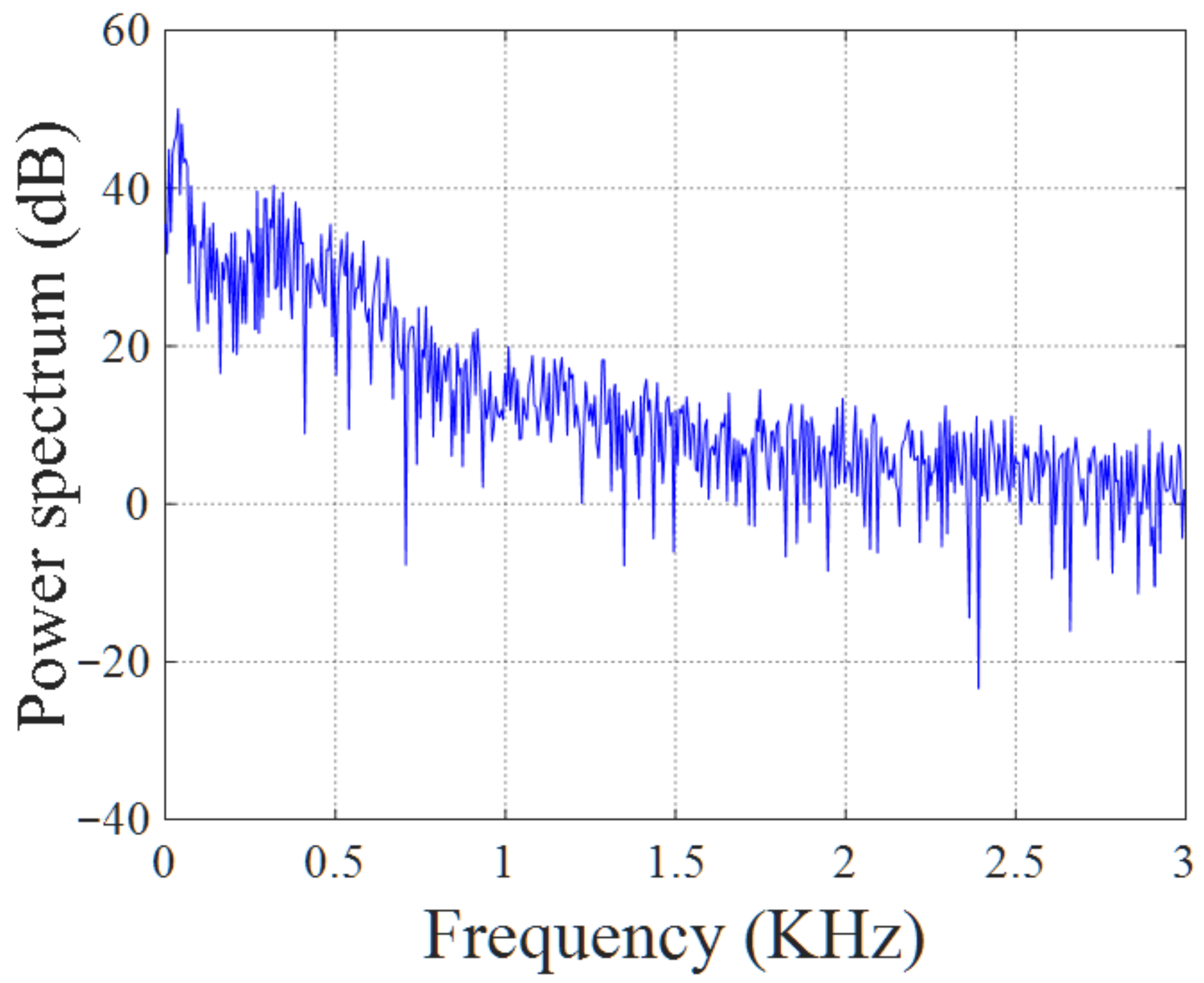
Note that the output signal obtained from the dynamical Lur’e system in
Figure 4 is characteristic of the broad band chaotic spectrum. The Fast Fourier Transformer (FFT) is applied on the chaotic signal. Then, the power spectrum of the output signal
can be obtained, as shown in the
Figure 9, for the time delay
and sampling frequency
. This base band spectrum deploys below the frequency range of 3 kHz. Thus, the chaotic signal is classified with a Very-Low Frequency (VLF) chaotic band, and such a feature allows direct long-wave chaotic radar system to be built for anti-stealth applications [
2].
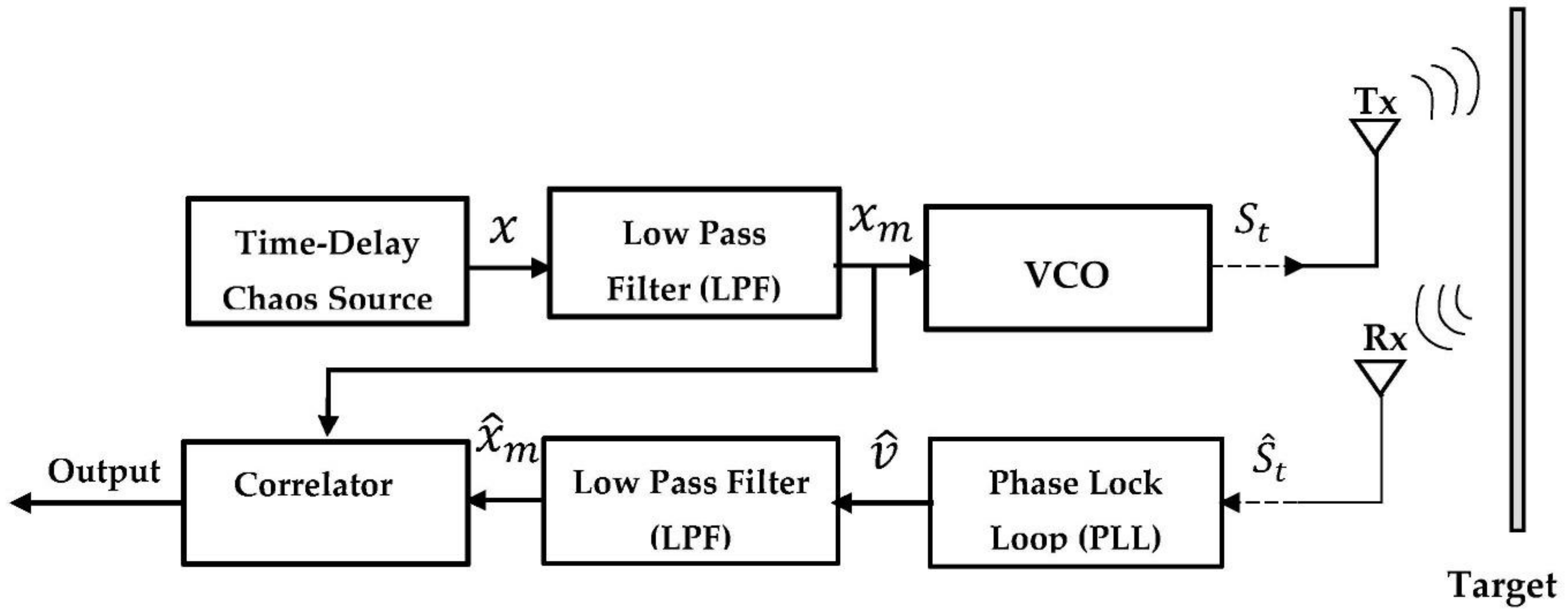
6. Chaotic Signal-Based on FM Modulation
After we generated the chaotic attractor from the time-delay chaotic system in
Section 5, we could use it in the FM modulation. Thus
Figure 10 and
Figure 11 show the chaotic signal’s modulation and demodulation structures, respectively. The voltage control oscillator (VCO) is used to modulate the chaotic signal and generate continuous FM signals. The low-pass filter (LPF) receives the output signal from the time-delay chaos source block (the master signal
) and assuming the cutoff frequency of LPF (
), first-order, and with the Butterworth method). Then, the limited chaotic master signal (
) is regarded as an input signal to the VCO during the modulation process. Then, the output signal from the VCO becomes a transmitted signal (
) through wireless channel [
4,
35].
where the carrier frequency is
and the sensitivity of the VCO in
is
, and
where
and
are the minimum and maximum frequency, while
and
denote the minimum and maximum voltages of
, respectively. The difference between maximum and minimum frequencies has represented the bandwidth (
) of the modulated signal and the instantaneous frequency deviation described in the term
. The nonlinear frequency relation is between the input of the master signal to VCO and the transmitted signal (
), as noted in Equation (5). The received signal
is demodulated by the analog Phase-Locked Loop (PLL), as shown in
Figure 11.
As shown in
Figure 11, a PLL consists of three components: a VCO, a low pass filter (LPF), and a mixer. Here, the LPF is built with
, first order, Butterworth method. The phase detector (PD) acts as a mixer to compare the phase of the received signal
with the phase of the VCO. The output signal of PD represents the error voltage (
), which is filtered by the loop LPF. However, this signal is amplified by the loop gain
and is assumed to produce
that later feeds the VCO. Subsequently, the output signal from the VCO (
) is multiplied by the received signal
to obtain
. Then, the output of the VCO is described as [
4,
35,
36]:
where,
and the voltage amplitude of the VCO output signal is
. Then, the output of the LPF can be described by
where the phase of
is
. The phase difference
will equal zero if the PLL is locked on the phase of the incoming signal
, and the nonlinear (sinusoidal) may be discarded; therefore, the Equation (10) can be rewritten as follows:
Later, the output from PLL (represented by ) becomes as an input to another LPF (which is chosen with , 3rd order, and Butterworth method) to recover . Then, the performance of the proposed continuous chaotic radar system can be measured by the final output of the correlated over the noisy wireless channel. The correlation qualities are used to assess the chaotic radar’s performance. Thus, the time-delay chaos source (transmitter system) parameter values have been carefully chosen as follows: , and with parameters (, ), and the initial condition is set to .
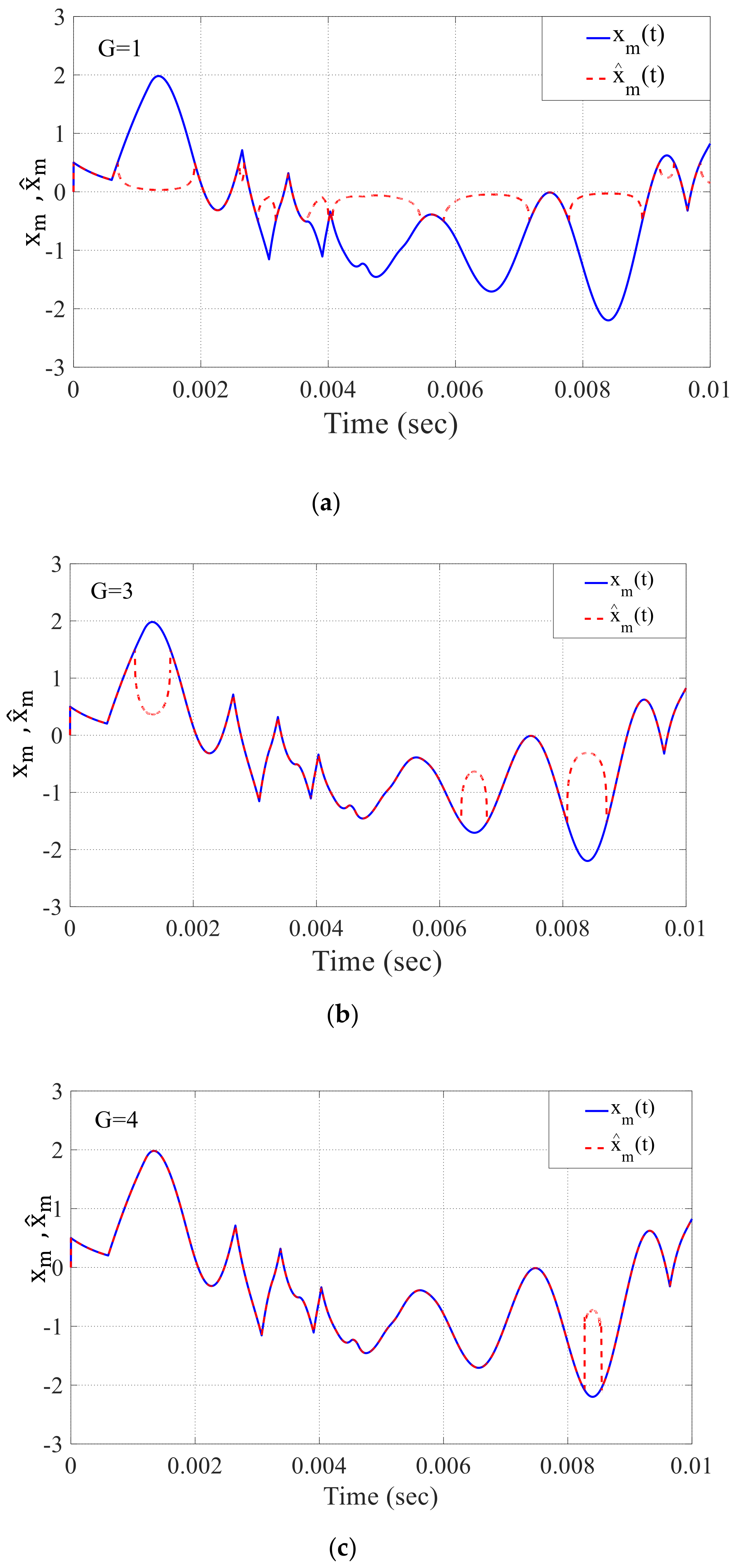
Now, the effect value of the loop gain
on the recovered signal
from the PLL can be seen in
Figure 12a–d, where the right
value must be carefully chosen for the recovered signal
. As a result, it is apparent that when the loop gain value becomes 4.6, it has a significant impact on the recovering signal. The resulting signal
closely resembles the original signal
.
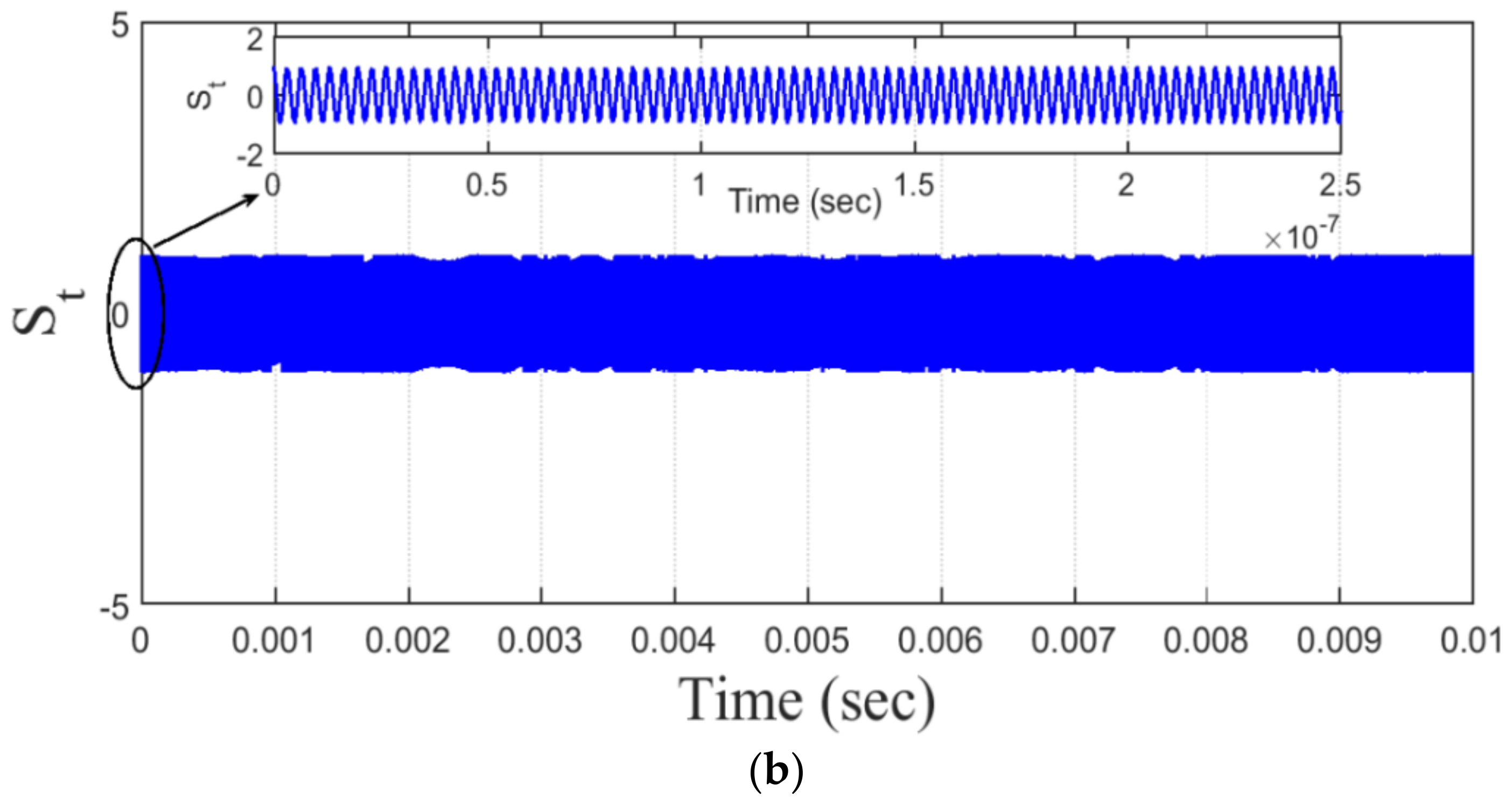
On the other hand, once the PLL locks on the original signal, we will examine the effect of the various noise values on the
over the wireless channel, assuming the sampling frequency,
, and echo delay (
) =
. Upon these assumptions,
Figure 13 and
Figure 14 show the limited continuous baseband signal
with bandwidth (BW) = 1 MHz and the output signal
from the VCO with a carrier frequency
fc = 0.3 GHz, loop gain
G = 4.6, and
MHz, respectively. Note that the effect of the time delay in
Figure 13, for instance
, shows more chaos dynamics generated in the transmitted FM signal as compared to the counterpart signal in case of
, depicted in
Figure 14. These FM signals are generated using the chaotic attractors obtained in
Figure 8a,b.
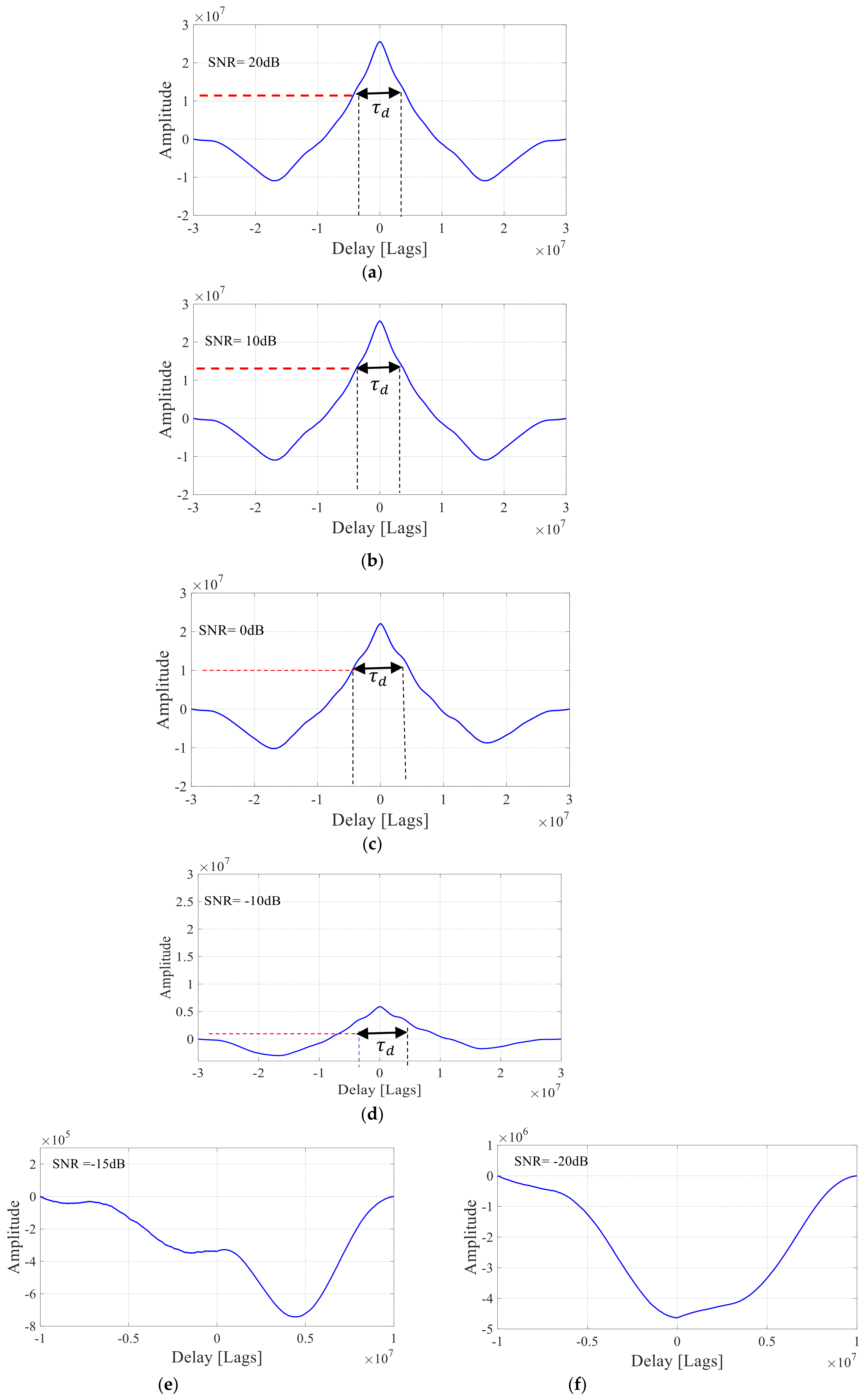
Furthermore, the correlation performance of the proposed mono-static radar system is also estimated under various values of signal-to-noise ratio (SNR) when VHF (very high frequency) chaotic signal based on FM is considered. Under the effect of noise, the PLL is locked on the phase of the incoming signal
, and the recovered signal
disappears when the noise becomes below the value of SNR = −10 dB, as shown in
Figure 15e,f. Meanwhile, a clear peak in cross-correlation performance can provide the desired information about the target, as shown in
Figure 15a, when
.
7. Comparative Performance with Existing Chaotic Radars
This section clarifies the performance of existing systems in comparison to the time-delay based chaotic radar systems. For example,
Table 1 compares the direct time-delay feedback chaotic radar [
2] with Colpitts oscillator-based radar [
8]. In contrast,
Table 2 summarizes the comparison of Indirect FM Chaotic Radars for the proposed time-delay feedback radar versus Lorenz-based Radar [
9,
10,
13]. Likewise, a signal design for generating wideband quasi-Frequency Modulated (FM) waveforms using chaotic systems was also suggested for joint radar-communication (RadComm) systems [
37]. However, the receiver design is based on a self-synchronizing chaotic system in place of PLL in order to make fast synchronization and a robust system against the Doppler.
Table 1.
A comparison example of the direct Chaotic Radars.
Table 1.
A comparison example of the direct Chaotic Radars.
| Type of Direct Radar | SNR Range | Synch. Type | Parameters
Mode | Bandwidth |
|---|
| Based on Colpitts Oscillator [8] | −20 dB | Error Feedback | Match | Wide-band (f > 1.6 GHz) |
| Based on Time-Delay Feedback [2] | −60 dB
−50 dB | Adaptive Observer Pecora and Carroll (PC) | Match and Mismatch | Broadband
(f < 3 kHz) |
Table 2.
A comparison of indirect FM Chaotic Radars when a time-delay feedback radar with echo delay = 2 ns.
Table 2.
A comparison of indirect FM Chaotic Radars when a time-delay feedback radar with echo delay = 2 ns.
| Indirect Radar | SNR Range | Synch. Type | Bandwidth | Simulation |
|---|
Lorenz-Based Radar
(Bistatic Radar) | 6 dB | Pecora & Carroll (PC) (complete) | Wide-band
fc = 2.5 GHz, [9] | Advanced Design System (ADS) |
| 17 dB | Projective | fs = 10 GHz, [10]
B.W = 500 MHz [13] |
Proposed Time-Delayed Feedback
(Monostatic Radar)- −
Proposed Time-Delayed Feedback - −
(Monostatic Radar)
| −15 dB | Phase Locked Loop (PLL) | Wide-band
fc = 0.3 GHz
fs = 5 GHz
B.W = 150 MHz | MATLAB Simulink |
Overall, it is noticed that our system based on PLL synchronization can also outperform in terms of low SNR range. It achieves successful recovery at SNR up to −15 dB.
On the other hand, when utilizing Matlab software, it was noticed that the simulation of FM-based time-delay chaotic radar had some problems. In fact, the massive data generated during signal processing (i.e., sampling-interval in ns) led to a storage limitation. Here we set the simulation stop time = 0.07 s to achieve the proper operation. Accordingly, the correlation forms in
Figure 15 can exhibit satisfactory peaks but with less resolution; however, in the case of direct chaotic radar [
2], once the simulation stop time is set to be 0.5 s, then the correlation peaks become more accurate by 50 times of the FM-based chaotic radar. As a result, one can conclude that more intensive research is needed to eliminate this difficulty in future work in order to create more realistic simulation findings.
8. Conclusions and Perspectives
The recent interest in chaos opens more trends to develop different secure applications in radar communication systems. Indeed, the key issue for modern military and civil radars still depends on how to let the radar exhibit more robustness over a wide-band noise. In this paper, to overcome the problems encountered in VLF and other VHF radar systems, such as radar size, large transmission energy, and less precision in range resolution, we developed a new 0.3 GHz indirect mono-static FM-based chaotic system which is based on a time-delay chaotic system. Here, the main contribution is to utilize the Phase-Locked Loop (PLL) for the synchronization process in this radar in order to detect the target’s echo signal accurately under different noise levels and with less design complexity. Thus, the loop gain (G) is carefully set when utilizing PLL in this model. This means that the system has been successfully designed with no need to utilize any complete self-synchronization or complex projective synchronization such as adaptive observer to correctly recover the echo signal.
Nevertheless, the effect of sampling interval (in ns) utilized in designing this system begets some restrictions on the signal processing during the simulation process. Therefore, the simulation stop time is set at 0.01 s for proper operation, and hence the robust indirect chaotic radar can be implemented. As a result, such a radar system is considered as one of the state-of-the-art models to detect the target over a high noisy environment and less degradation in the recovered echo signal.
Upon these results, this work can identify some aspects for further study, as follows: (i) The Doppler effect of the echo signal needs more intensive investigation using ambiguity function for moving targets. (ii) To provide a high range resolution, the indirect chaotic radar based on FM can be developed to operate in wider microwave bands (e.g., beyond 1 GHz–3 GHz). Moreover, the different hyperchaotic systems may be also suggested to design monostatic/bi-static radar systems using FPGA. (iii) On the other hand, adaptive control schemes and Artificial Neural Network (ANN) are also eligible to make and predict the synchronization of this time-delayed chaotic system, particularly in secure image encryption/decryption applications.


 ,
, 


