Article

Online Sparse DOA Estimation Based on Sub–Aperture Recursive LASSO for TDM–MIMO Radar

1
School of Information and Communication Engineering, University of Electronic Science and Technology of China, No. 2006, Xiyuan Ave., West Hi–Tech Zone, Chengdu 611731, China
2
Yangtze Delta Region Institute, University of Electronic Science and Technology of China (UESTC), Quzhou 324003, China
3
Centre for Mathematical Sciences, Lund University, 221 00 Lund, Sweden
*
Author to whom correspondence should be addressed.
Submission received: 3 March 2022 / Revised: 21 April 2022 / Accepted: 27 April 2022 / Published: 29 April 2022

Abstract

:
The least absolute shrinkage and selection operator (LASSO) algorithm is a promising method for sparse source location in time–division multiplexing (TDM) multiple–input, multiple–output (MIMO) radar systems, with notable performance gains in regard to resolution enhancement and side lobe suppression. However, the current batch LASSO algorithm suffers from high–computational complexity when dealing with massive TDM–MIMO observations, due to high–dimensional matrix operations and the large number of iterations. In this paper, an online LASSO method is proposed for efficient direction–of–arrival (DOA) estimation of the TDM–MIMO radar based on the receiving features of the sub–aperture data blocks. This method recursively refines the location parameters for each receive (RX) block observation that becomes available sequentially in time. Compared with the conventional batch LASSO method, the proposed online DOA method makes full use of the TDM–MIMO reception time to improve the real–time performance. Additionally, it allows for much less iterations, avoiding high–dimensional matrix operations, allowing the computational complexity to be reduced from O K 3 to O K 2 . Simulated and real–data results demonstrate the superiority and effectiveness of the proposed method.
Keywords:
LASSO; TDM–MIMO; DOA; online

1. Introduction

In recent years, colocated multiple–input, multiple–output (MIMO) technology has received increasing amounts of attention and has been extensively used for assisted driving, remote sensing [1], geological exploration [2], and free space optics communication (FSOC) [3]. In radar remote sensing applications, the MIMO technology improves the angular resolution while reducing the physical channel count and antenna aperture, compared with conventional array antennas [4,5,6]. In FSOC applications, MIMO technology is also utilized to overcome attenuation and turbulence effects in atmospheric channels, thereby obtaining channel gain and improving the reliability of FSOC systems [7,8]. In terms of hardware complexity, the frequency–modulated continuous wave (FMCW) sequence of time division multiplexing (TDM) is the simplest option for colocated MIMO. Therefore, more practical applications and mechanistic studies are achieved in this way [9,10,11].
Targeted direction–of–arrival (DOA) estimation is an important research hotspot in MIMO radar signal processing [12]. The most fundamental method is the classical delay–and–sum (DAS) approach, which recovers a target source by weighting and delaying the echoes. However, the DAS approach suffers from a low angular resolution and a high side lobe. Moreover, the resolution of the DAS approach can only be improved by increasing the number of channels, which is very uneconomical. Many methods have been proposed to effectively improve the DOA resolution of MIMO radar [13,14,15,16,17,18,19,20]. Based on the rotational invariance property of spatially correlated matrix signal subspaces, the estimation of signal parameters via the invariance technique (ESPRIT) algorithm was proposed to improve the DOA estimation accuracy of MIMO radar [13,14]. The parallel factor analysis (PARAFAC) algorithm was proposed to improve the multitarget resolution [15]. A dimensionality–reducing Capon method has been proposed for the DOA estimation of monostatic MIMO radars [17], and this method reduces the dimensions of the MIMO radar sub–aperture through a dimensionality–reducing transformation, thereby accelerating the Capon algorithm. In [1,21], the iterative adaptive approach (IAA) was introduced for MIMO radar imaging, and it was shown that the IAA can work with few or even a single snapshot, and can provide a higher azimuthal signal source localization accuracy. However, this method suffers from a high computational complexity due to its high dimensional matrix inverse computation per iteration. The sparse representation (SR) has been used in an estimation method that contains DOA estimation for colocated TDM–MIMO radars [19]. The least absolute shrinkage and selection operator (LASSO) method [22] is an efficient tool in the fields of application of sparse linear regression [23,24]. This method consists of a linear least square optimization regularized by an additional penalty term of the L 1 –norm as a measure of sparseness. The LASSO method is demonstrated to improve the DOA estimation performance of the array signal, with higher resolution and a lower side lobe [25]. Due to its superiority, many studies have been carried out on LASSO, including computational efficiency and theoretical analysis, etc. [26,27,28].
In spite of the performance gain, the current batch LASSO algorithm can only handle the complete aperture data already acquired by the MIMO radar. Since the LASSO algorithm requires operations, such as matrix inversion and matrix multiplication and a large number of iterations; the computational complexity of batch implementation is notably high, especially for massive TDM–MIMO data sets. There are several advances in algorithmic acceleration that might be combined with the LASSO algorithm to mitigate the computational burden. Some fast matrix inversion methods, such as the Newman series [29] and Jacobi method [30,31], were proposed to handle the problem of high computational complexity. In [32,33,34], the Neumann series (NS) is considered to perform matrix inversion approximation (MIA). The main contribution of the Neumann method is to convert the matrix inverse calculation into matrix multiplication, which is more suitable for hardware platforms, but the complexity is equal to or higher than that of the exact calculation method, such as the QR–based method [33]. The Jacobi method reduces the complexity from O K 3 to O L K 2 , where L is the number of iterations. However, the Jacobi method converges slowly and, thus, implies higher latency [35]. Although the above fast matrix inversion methods can reduce the computational complexity of the matrix inversion, the approximation error is introduced, which should be carefully controlled. Furthermore, they only reduce the complexity of the matrix inversion, whereas the burden caused by high–dimensional matrix multiplication and a large number of iterations in the batch LASSO algorithm cannot be well handled.
To solve the high–complexity problem of the LASSO method, this paper presents a sub–aperture recursive LASSO method to allow for online DOA estimation. Online processing refers to the way of processing comparing with the traditional batch processing [28,36,37]. In the way of batch processing, the processor must wait for collecting the measurement completely, and process the measurement taking additional time cost. In contrast, online processing processes the stream of MIMO sub–aperture measurements accordingly; that is, updating the result when a new sub–aperture measurement is available. The benefit of online processing is that it can save the time cost of measurement collection. Meanwhile, online processing also allows for much less iterations, avoiding high–dimensional matrix inversion and multiplication. From the following analysis, it can be seen that the computational complexity can be reduced from O K 3 to O K 2 .
This paper is structured as follows. In Section 2, the MIMO radar signal model is reviewed and the TDM–MIMO sub–aperture data reception scheme is derived. Then, the proposed online TDM–MIMO radar DOA estimation method is derived in detail. In Section 3, simulated and real–data results demonstrate the effectiveness of the proposed method. In Section 4, the quantitative comparison and future work are discussed. Section 5 presents the conclusions.

2. Materials and Methods
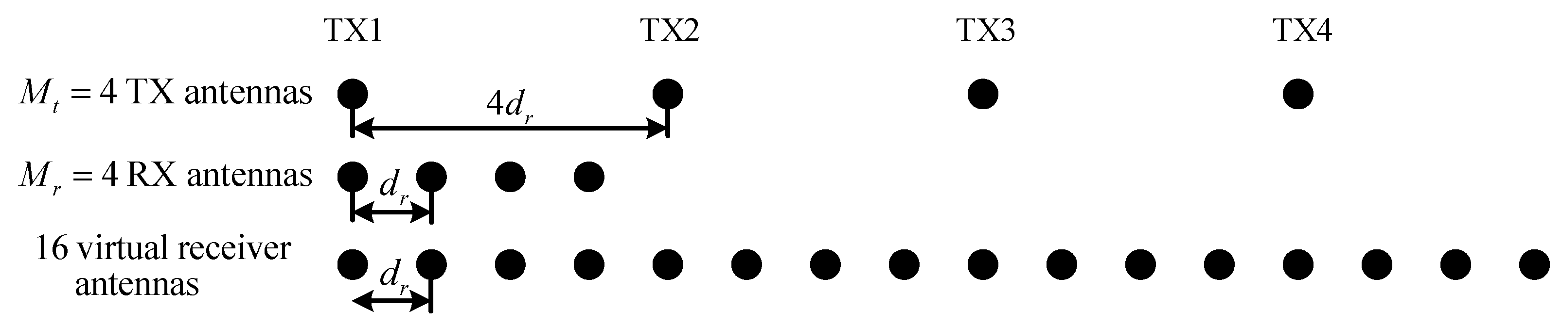
A colocated MIMO radar that contains isotropic uniform linear receiving and transmitting arrays (ULA) is considered. The receiving array element spacing is d r = λ / 2 , where λ denotes the carrier wavelength. The location distributions of M r receiving antennas and M t transmitting antennas are shown in Figure 1 (with four transmitters and four receivers as an example). The transmitting array element spacing is d t = M t · d r . According to the MIMO theory, the equivalent virtual array of this MIMO can be considered a single–input, multiple–output (SIMO) antenna with 16 elements.

2.1. Signal Model

Suppose that there are K impinging signals with angular parameter, θ k , k = 1 , , K . According to Figure 1, the steering expression of the m-th virtual array element is written as
a θ k = exp j m 1 d r sin θ k = exp j m t 1 d t sin θ k · exp j m r 1 d r sin θ k
where m t = 1 , 2 , , M t and m r = 1 , 2 , , M r represent the sequence number of transmitting and receiving array elements, respectively. In addition, m , m t and m r satisfy the relationship m = m t 1 M r + m r . For all virtual elements, the steering vector can be denoted as
a θ k = a 1 θ k , a 2 θ k , , a M θ k T
where M = M t · M r . We assume that there are L TDM periods and each period contains N pulses. Hence, the -th complex baseband receiver signal y C M can be denoted as [19]
y = exp j · γ ω d a θ k 1 N s + e
where ⊙ represents the Hadamard product, s the unknown and deterministic target signals, e the additive zero mean Gaussian noise, and σ 2 the variance. ω d denotes the Doppler frequency of the target. γ = t 1 M r represents the TDM–induced Doppler frequency shift (DFS), where t = t 1 , t 2 , t 3 , t 4 represents the time–division scheme of the signal transmission, and 1 M r denotes the full one–column vector with a length of M r .
To simplify the model, it is assumed that ω d = 0 , and N = 1 . For the -th snapshot of a given TDM period, model (3) can be simplified to
y = As + e
where the steering matrix is given by
A = a θ 1 , a θ 2 , , a θ K = b 1 * b 2 * b M * C M × K
The receiver signals y of the M channels are arranged as 1 , 2 , , M t according to the sub–aperture order.
The TDM–MIMO radar system transmits the signals in a time–division manner per the transmitting scheme, as shown by Figure 2a. Only one transmitting antenna is available for each time slot. In the case of the four receivers, the received signals are shown in Figure 2b. The blocks with order 1–4 denote the sub–aperture data received in the first period, and so on. Any set of sub–apertures is equivalent to a SIMO subarray with M r receivers. In the traditional batch processing method, all sub–aperture data must be received completely to formulate the full–aperture data before processing. When dealing with a massive TDM–MIMO data set, the dimension of aperture data will become quite high. As a result, the high dimensionality of the full–channel data increases the temporal and spatial complexity. Moreover, the period of reception will introduce additional delay. Both of these reasons lead to poor real–time performance of batch processing. To solve this problem, we propose an online processing method that processes sub–aperture data along receiving. The proposed method allows beamforming to begin directly after the first sub–aperture data are received. Doing so introduces two benefits, one is that it can save the time cost of measurement collection, the other is that online processing allows for much less iterations, avoiding high–dimensional matrix inversion and multiplication, resulting in lower temporal and spatial complexity.

2.2. Proposed Method

Based on model (4), the LASSO method attempts to recover s by solving the following convex optimization problem [22]
arg min s C K y As 2 2 + λ s 1
where λ is a parameter that weighs the sparsity of s . Equation (6) can be solved directly by convex optimization, such as the CVX tool box in MATLAB. However, the source code is not open, which cannot be ported to a hardware platform. In recent years, many iterative methods, such as split Bregman [38], IRLS [39], etc., have been proposed. For example, the split Bregman solution can be written as [38]
s ^ q + 1 = μ A * A + λ I 1 μ A * y + λ d q b q d q + 1 = shrink s ^ q + 1 + b q , 1 / λ b q + 1 = b q + s ^ q + 1 d q + 1
where d and b denote the introduced temporary vectors, μ an additional regularization parameter, q the iteration number, I the identity matrix. The function shrink ( x , η ) = sign ( x ) max ( | x | η , 0 ) , and sign ( · ) denotes the sign function.
It is seen that matrix inversion, matrix multiplication, and a considerable number of iterations are required, so the computational complexity is quite high, which is not suitable for engineering applications. To solve this problem, starting from the cyclic minimization [28,40,41], we propose a subaperture recursive online processing method.

2.2.1. Cyclic Minimization

By the minimization of Equation (6), only one component s i in s is considered at a time. Let y ˜ i y k i a k s k . Then, the cost function can be written as [28]
J s i = y ˜ i a i s i 2 2 + λ s i
To solve the scalar minimization problem, the i-th variable to be solved is transformed into the polar form s i = r i e j θ i , where r i 0 and θ i π , π . Then, the quadratic term in Equation (6) can be rewritten as
y ˜ i a i s i 2 2 = y ˜ i a i r i e j θ i 2 2 = y ˜ i 2 2 + a i r i e j θ i 2 2 2 Re r i a i * y ˜ i e j θ i = y ˜ i 2 2 + a i 2 2 r i 2 2 r i a i * y ˜ i cos arg a i * y ˜ i θ i
By substituting (9) into (8), a cost function with r i and θ i denoting independent variables is obtained
J r i , θ i = y ˜ i 2 2 + a i 2 2 r i 2 2 r i a i * y ˜ i cos arg a i * y ˜ i θ i + λ r i
According to (10), the minimized θ ^ i can be expressed as
θ ^ i = arg a i * y ˜ i
Then, let
α i y ˜ i 2
β i a i 2
γ i a i * y ˜ i
where * denotes the conjugate transpose of a matrix. Hence, Equation (10) can be rewritten as
J r i , θ ^ i = α i + β i r i 2 2 γ i r i + λ r i
The first–order and second–order derivatives of Equation (13) are
d J d r = 2 β r 2 γ + λ
d 2 J d r 2 = 2 β = 2 a i 2 0
Therefore, (13) is convex, and the minimization of r should be achieved at d J / d r = 0 and denoted as
r ^ i = max 2 γ i λ 2 β i , 0
Ultimately, the element–level minimization can be expressed as [28]
s ^ i = r ^ i e j θ ^ i , if γ i > λ / 2 0 , e l s e
According to Equations (16) and (11), when updating each element s ^ i , the convex optimization cost function (8) decreases monotonically. Therefore, the result s ^ of the target source distribution can be achieved by traversing i = 1 , 2 , , K for Equation (17).

2.2.2. Proposed Online Strategy

For TDM–MIMO radars, the sub–aperture data arrive sequentially over time. The p-th sub–aperture data and the corresponding steering matrix can be expressed as
y p y p M r M r + 1 y p M r , A p b p M r M r + 1 b p M r
Vector y p C M r contains data for the p-th sub–aperture, and the length is M r , i.e., data blocks 1–4 in Figure 2b (if p = 1 ). Similarly, the steering matrix A p C M r × K contains the steering vectors of the corresponding subarray elements. The optimization problem (6) can then be rewritten as
arg min s R K y p A p s 2 2 + λ s 1
Let s R K denote the estimated result from the p 1 -th sub–aperture data. Based on the cyclic minimization, we first introduce an intermediate variable z p = y p A p s that can be eliminated in subsequent derivations. Then, y ˜ p , i = z p + a p , i s i C M r , which is substituted into Equation (12)
α i = y ˜ p , i 2 = z p + a p , i s i 2 = z p 2 + a p , i 2 s i 2 + 2 Re s i a p , i z p
β i = a p , i 2
γ i = a p , i * y ˜ i = a p , i * z p + a p , i s i
where s i denotes the current estimate of the i-th direction, and a p , i C M r the steering vector of the i-th direction for the p-th sub–aperture, namely, the i-th column of Ap.
The intermediate variable
ζ p = A p * z p C K
and recursive calculation variables are introduced:
Γ p A p * A p = Γ p 1 + b p b p * C K × K
ρ p A p * y p = ρ p 1 + b p y p C K
In minimizing r i , only the calculation of β i and γ i is needed. Considering Equation (22), the expression (20) can be simplified to
β i = Γ i i p
γ i = ζ i + Γ i i p s i
where ζ i denotes the i-th element of ζ p , and Γ i i p the i-th diagonal element of matrix Γ p . Similarly, Equation (11) can also be represented by recursive variables as
θ ^ i = arg ζ i + Γ i i p s i
Hence, the i-th element of the DOA is obtained:
s ^ i = r ^ i e j θ ^ i
By traversing i = 1 , 2 , , K for Equations (24)–(26), the target source distribution result s ^ obtained by solving the p-th sub–aperture data are obtained. Variables z p can be updated through z p = z p + a p , i s i s ^ i . Then, according to (21), the update of ζ p can be written as
ζ p = A p * z p = ζ p + Γ i p s i s ^ i
where Γ i p denotes the i-th column of Γ p .
For each new sub–aperture data block, ζ p is initialized to ζ p = ρ p Γ p s . For the first sub–aperture ( p = 1 ), the estimate is initialized as s = 0. Furthermore, the cyclic calculation (24)–(27) requires Q iterations. According to experience, good results are usually obtained after 8 to 10 iterations.
With the arrival of the subsequent MIMO sub–aperture data, the DOA result s ^ can be obtained by reiterating (21)–(27) using Equation (21) (which is achieved through the previous result s by the previous p − 1 sub–aperture data) and the new sub–aperture data yp. The online processing flowchart for the sub–aperture update is shown in Figure 3.

2.2.3. Computational Complexity Analysis

The computational complexity of the DAS method, the IAA method [1,21,42], the traditional LASSO method, and the proposed method are compared, as shown in Table 1.
From Table 1, it is seen that the proposed methods reduce the computational complexity by an order of magnitude compared with the IAA and LASSO method. In addition, the complexity of the proposed method can reach the order of magnitude of the RLS method ( O K 2 ). Table 2 shows the computational complexity for the methods with K = 4 M r M t and varying M r × M t . Typically, when M r × M t = 1000 , the proposed method reduces the required computational time by 194 times and 37 times, compared with the LASSO and IAA, respectively.

3. Results

In the simulation and experimental verification, both the target and the platform are considered stationary. All of our simulations and experiments were conducted using a 64–bit MATLAB R2018a on a PC workstation with an Intel Core i5–9500 CPU, 3.0 GHz and 16 GB RAM. The proposed method is compared with the conventional DAS, IAA, and LASSO methods in terms of computational time and DOA accuracy. Because this study only concerns the angular estimation performance, the targets were set at the same distance. The root mean square error (RMSE) of the angular estimates is used for evaluating the performance of simulation results and is defined as
RMSE = 10 log 10 1 P p = 1 P θ ^ p θ p 2
where θ p denotes the true target value of the p-th target grid, and θ ^ p represents the estimate of the p-th target grid. The signal–to–noise ratio (SNR) is defined as
SNR = 10 log 10 P s δ 2
where P s stands for the signal power, and σ 2 is the variance in the additive Gaussian white noise.

3.1. Simulation Results

The azimuth of two unrelated sources with equal power is assumed to be 5 , 0 . The scan range is between 90 and 90 , and the number of points is K=512. The SNR of the signal is SNR = 10 dB . A MIMO radar system with two transmitters and four receivers (carrier frequency f c = 77 GHz ; receiving array element spacing: d r = λ / 2 = 1 . 9 mm ; transmitting array element spacing: d t = M t · d r = 7.6 mm ) is investigated.
Figure 4a illustrates the results of 10 Monte Carlo experiments with the traditional DAS method. Although the average processing time is only 0.0002 s, effectively distinguishing between the two adjacent targets is impossible. Figure 4b shows the results of the 10 Monte Carlo experiments with the IAA method. The average processing time is 0.0879 s. The results of the 10 IAA experiments show lower side lobes, and the adjacent targets are basically distinguished and located, which is better than that shown in Figure 4a.
However, the IAA method also has drawbacks, such as an unsatisfactory resolution, a high side lobe, and high computational complexity. Figure 4c shows the results of the 10 LASSO experiments. It is seen that they can well distinguish the adjacent target directions, and the angular estimation error is highly non–significant. Nonetheless, the LASSO method has a high algorithmic complexity and requires the support of complete aperture data, thus exhibiting poor real–time performance. Furthermore, its average processing time is 0.2403 s. As shown in Figure 4d, the 10 results of the proposed method are nearly consistent with the LASSO results. Compared with the results of the traditional DAS and IAA methods, the results of the proposed method provide better resolving of adjacent targets and side lobe suppression.
The average processing time for each sub–aperture data update takes only 0.0215 s. Furthermore, Figure 5 illustrates the DOA result at the arrival of each sub–aperture data block under simulation conditions by the proposed method. The real–time DOA results are progressively improved as the MIMO sub–aperture data are received, and the best performance is achieved at the receipt of the last data block (the DOA performance of the LASSO method). Figure 6 shows the RMSE and CRB of angle estimation by the four methods for SNRs ranging from 5 to 30 dB [44].
Moreover, we can reduce the estimation error of DOA by compensation in two ways. One is the compensation for mutual coupling of array elements [45,46]. The other is the motion compensation: the Doppler phase needs to be considered for the moving platform [47,48]. Good research has been carried out on the above two compensation ways. Because this article mainly focuses on real–time signal processing algorithms, it will not be further discussed here.

3.2. Measurement Results

3.2.1. One–Dimensional Point Target Experiment

In this section, two adjacent corner reflectors and a MIMO radar with two transmitters and four receivers are used to verify the DOA performance of the proposed method. The layout of the radar system and corner reflectors is shown in Figure 7a; the corner reflectors are illustrated in Figure 7b. The radar and corner reflectors are at the same height, and the carrier frequency of the former is 77 GHz.
Figure 8a shows the DOA result of the DAS method for which the processing time is 0.0024 s. Due to the short distance between the two corner reflectors, their azimuths are indistinguishable. Figure 8b shows the DOA result of the IAA method for which the processing time is 0.1304 s. Figure 8a,b are consistent with the corresponding simulation results. This method effectively improves the DOA in resolution. The corner reflector is clearly separable, but the side lobes are still not well suppressed.
Figure 8c shows the DOA result of the LASSO method for which the processing time is 0.2139 s. By taking advantage of the sparseness of the target sources, the LASSO method distinguishes the targets very well, and the side lobe is also quite well suppressed. Compared with traditional methods, the resolution is greatly improved. However, the LASSO method is not applicable to the real–time processing of TDM–MIMO systems. Figure 8d shows the DOA result of the proposed method. This method maintains the same angular resolution as the LASSO method and can update the DOA results of the targets in real time as the MIMO sub–aperture data are received in real time. In addition, the proposed method offers excellent online processing and a super–resolution capability. The average processing time for each sub–aperture data update is 0.0318 s. According to the peaks, the angular estimation errors of the LASSO method and the proposed method are 0 . 15 and 0 . 17 , respectively, after comparing with the calibrated average angle of the targets.

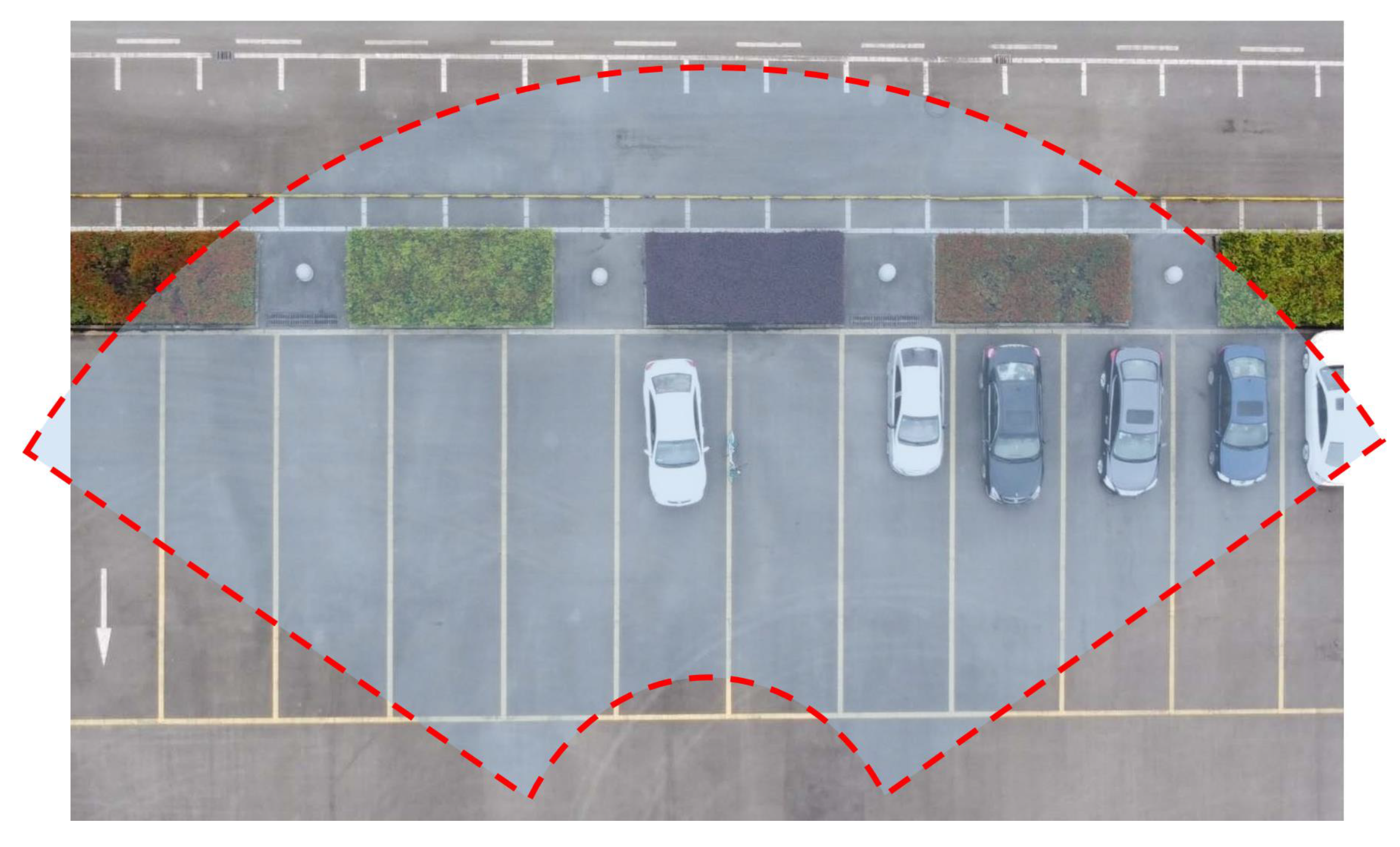
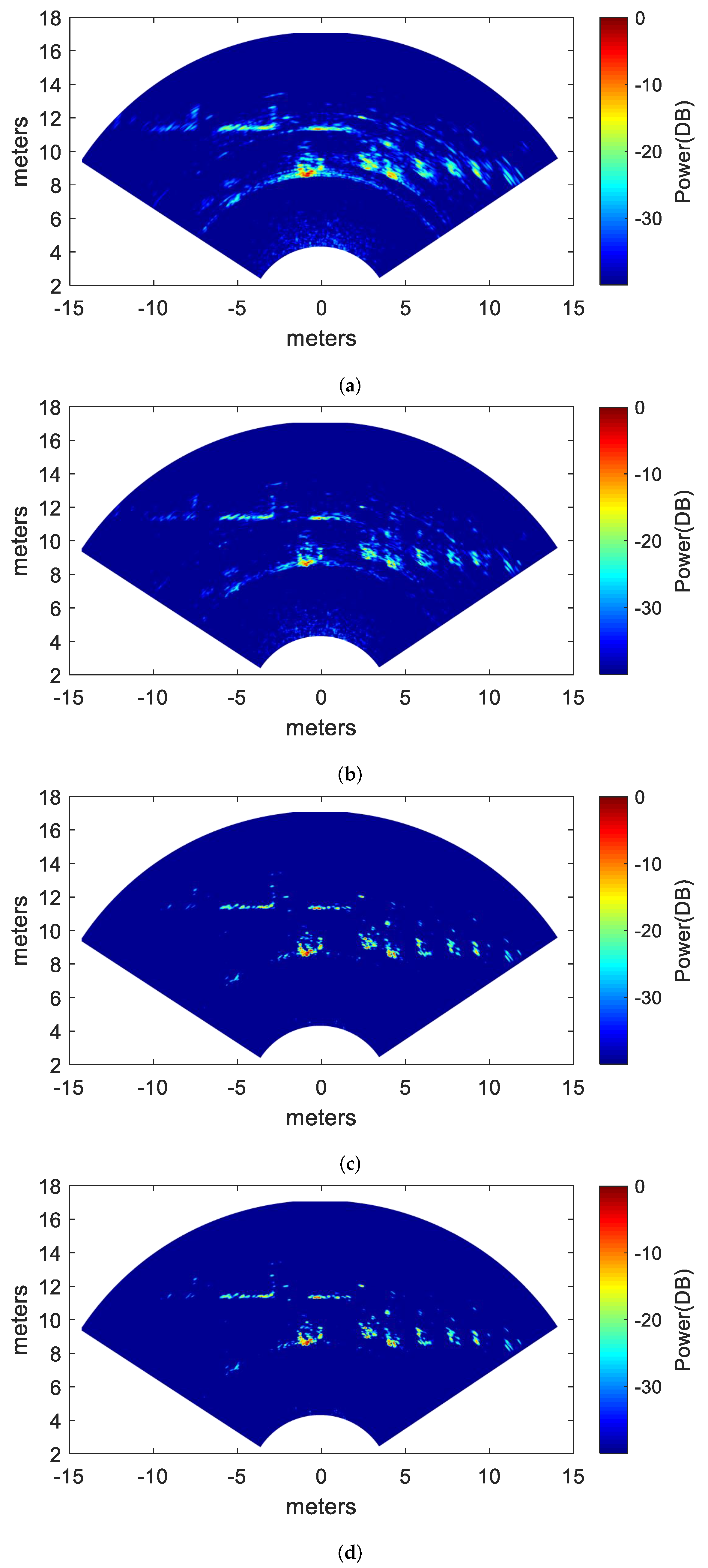
3.2.2. Two–Dimensional Surface Target Experiment

In this section, MIMO radar data are used to verify the performance of the proposed method. The original optical scene photographed by the drone is shown in Figure 9. The experimental parameters are listed in Table 3. The carrier frequency, the number of array elements, and the beam width have a determined relationship, which mainly affects the azimuth resolution. The pulse width and pulse repetition interval affect the signal to noise ratio, and bandwidth affects the range resolution.
Figure 10a shows the 2D results of the DAS method for which the processing time is 0.0973 s. It is seen that a row of vehicles in the parking lot is vaguely distinguished. However, due to the low resolution and poor side lobe suppression ability of the DAS method, the imaging results with regard to the vehicle in the center of the scene suffer from high side lobes, and the vehicles on the right side of the scene are blurred. Figure 10b shows the 2D results of the IAA method [1] for which the processing time is 124.8980 s. It is seen that the resolution of this image is effectively improved. The side lobes of the strong scattering point are well suppressed. Figure 10c shows the 2D result of the LASSO method for which the processing time is 294.1526 s. It is seen that the resolution of this image is further improved. The side lobes of the car in the center of the scene are significantly suppressed, and the car contour becomes much clearer. The number and position of vehicles on the right side of the image can be easily determined. Unfortunately, both the IAA and the LASSO methods have enormous computational complexity, and cannot implement the online processing of the MIMO data. Figure 10d shows the 2D results of the proposed method for which the processing time is 4.8980 s. It is seen that this image is much better than that shown in Figure 10a,b. The proposed method maintains the same angular resolution as the LASSO method and can update the imaging results as the MIMO sub–aperture data are received in real time.
The image entropy (IE) [49] is employed to quantitatively evaluate the performance of the 2D surface target experiment, where low values of IE commonly indicate that the image is well recovered. The image entropy of the above processed results is shown in Table 4. It can be seen that the entropy of LASSO and the proposed method are smaller than that of the DAS and IAA methods. This proves that the results of LASSO and the proposed method are clearer than those of other methods. More importantly, compared with Figure 8c,d, it can be seen that the proposed method has almost no performance loss compared with the traditional LASSO.

4. Discussion

4.1. Results Analysis

In this paper, a LASSO–based sparse DOA estimation method for online processing of TDM–MIMO radar sub–aperture data is proposed. In this paper, a detailed comparison of the computational complexity, simulation results, measured data of point targets, and measured data of surface targets by various methods was carried out.
The results obtained in this paper show that the proposed online DOA method works well under both simulated and experimental conditions. It should be noted that the computational complexity of the IAA method in Table 1 does not consider the number of iterations, and its total computational complexity should be expressed as O Q M r M t 3 , where Q represents the number of iterations of IAA. Referring to the article [21], the iteration number of the IAA method is set to 15 in all simulations and measurements in this paper.
Since the proposed method can output DOA results from sub–aperture data in real time, we only give the complexity of each sub–aperture recursion in Table 1. The total calculation times of multiplication and division is expressed as Q + 1 M t K 2 + 9 Q + M r 2 + M r M t K , and the computational complexity is O Q + 1 M t K 2 , where Q represents the number of iterations of the proposed method. M t represents the number of transmitting array elements, namely, the number of recursions required for full aperture. M r represents the number of receiving array elements, namely, the sub–aperture length. In addition, according to the configuration of the transmitting and receiving array elements, M t and M r can also interchange roles.
Comparing (c) and (d) of Figure 4, Figure 8 and Figure 10, it is obvious that the proposed method can maintain the recovery performance of the traditional LASSO method while performing low–complexity online DOA estimation. It should be mentioned that the selection of parameter λ in Equation (7) refers to the article [28]. In the proposed method, λ = m t M r log 2 K , where m t = 1 , 2 , , M t is the current recursive sub–aperture ordinal.
In the follow–up research, on the one hand, under the conditions of the moving platform and moving target, Doppler phase and model error compensation need to be considered to further improve the DOA accuracy of the proposed method. On the other hand, after the motion compensation, the relevant hardware platform should be built to implement the TDM–MIMO data’s real–time processing on FPGA or DSP using the proposed method.

4.2. Extension to Optical Communication

In free–space optical communication, high–speed transfer of effective information can be achieved by quantum cascade laser (QCL) [50,51]. The article [52], discusses the possibility of realizing high–power broadband QCL. The article [53], demonstrates that optical radiation with a wavelength of about 10 µm in limited visibility is characterized by better transmission properties than near–infrared waves. The article [54] analyzes the performance of optical communication channels in the marine environment. The article [55] analyzes the performance of free space optics communication under atmospheric turbulence. This paper mainly discusses the TDM–MIMO radar in the microwave band. Moreover, in the field of FSOC, MIMO technology can be used to solve the problem in attenuation and atmospheric turbulence, which contributes to the atmospheric channel gain and the reliability of the FSOC system. In the article [8,56], a maximum likelihood parameter estimation method is used to improve the bit error rate (BER) performance of the MIMO FSOC system. Due to the large number of massive FSOC–MIMO antennas and the complex atmospheric turbulent propagation environment [3,57], the computational complexity of matrix inversion in the channel estimation is quite high. Therefore, traditional channel estimation methods cannot be directly applied in massive MIMO. A low–complexity massive MIMO channel estimation method must be employed. The proposed online sub–aperture recursive LASSO estimation method may also be employed to lower the estimation error and improve the running speed. This paper mainly discusses radar applications and the above articles belong to the field of communications. We should note that although the mathematical principle is the same, when this method is applied to MIMO optical communication, minor changes are required, and we will not go into much detail here.

5. Conclusions

In this paper, an sub–aperture recursive LASSO method is proposed for the online DOA estimation of TDM–MIMO radar using sub–aperture data blocks. The proposed method has two advantages. First, it makes full use of the TDM–MIMO reception time to improve the real–time performance of the DOA algorithm (i.e., online DOA estimation), and the complexity and memory usage per update are remarkably reduced when compared with traditional methods. Second, the proposed method is superior to the traditional DAS and IAA methods with respect to the DOA resolution because it can reach the DOA estimation accuracy of traditional LASSO methods. Simulations and experimental data verify the effectiveness of the proposed method. The online DOA estimation of actual TDM–MIMO radar will be realized through hardware programming in the future.

Author Contributions

Conceptualization, J.L. and Y.Z. (Yongchao Zhang); methodology, J.L.; software, Y.Z. (Yongwei Zhang); validation, J.L., Y.Z. (Yongchao Zhang), and Y.Z. (Yongwei Zhang); formal analysis, J.L.; investigation, J.L. and D.Z.; resources, J.L.; data curation, Y.Z. (Yongwei Zhang); writing—original draft preparation, J.L.; writing—review and editing, J.L.; visualization, Y.Z. (Yongchao Zhang); supervision, Y.Z. (Yongchao Zhang) and A.J.; project administration, Y.Z. (Yongchao Zhang) and A.J.; funding acquisition, Y.Z. (Yongchao Zhang), Y.Z. (Yin Zhang), Y.H., and J.Y. All authors have read and agreed to the published version of the manuscript.

Funding

This work was supported in part by the National Natural Science Foundation of China under grants 61901092, 61901090, and in part by the Special Science Foundation of Quzhou.

Institutional Review Board Statement

Not applicable.

Informed Consent Statement

Not applicable.

Data Availability Statement

This study did not report any data.

Conflicts of Interest

The authors declare no conflict of interest.

Abbreviations

The following abbreviations are used in this manuscript:
TDM  time–division multiplexing
MIMO  multiple–input multiple–output
DOA  direction–of–arrival
LASSO  least absolute shrinkage and selection operator
IAA  iterative adaptive approach
FMCW  frequency–modulated continuous wave
DAS  delay and sum
CRB  Cramer–Rao bound
SVD  singular value decomposition
ULA  uniform linear array
SIMO  single–input multiple–output
RMSE  root mean square error
SNR  signal–to–noise ratio

References

  1. Roberts, W.; Stoica, P.; Li, J.; Yardibi, T.; Sadjadi, F.A. Iterative adaptive approaches to MIMO radar imaging. IEEE J. Sel. Top. Signal Process. 2010, 4, 5–20. [Google Scholar] [CrossRef]
  2. Liu, H.; Zhang, Y.; Chen, Q.; Han, F.; Liu, Q.H. Reverse-time migration and full waveform inversion applied to a stationary MIMO GPR system. In Proceedings of the 2016 IEEE International Geoscience and Remote Sensing Symposium (IGARSS), Beijing, China, 10–15 July 2016; pp. 7446–7449. [Google Scholar]
  3. Hasan, S.M.A.; Ahmed, S.; Islam, A.N. Simulation of A Massive MIMO FSO System Under Atmospheric Turbulence. In Proceedings of the 2021 5th International Conference on Electrical Engineering and Information & Communication Technology (ICEEICT), Dhaka, Bangladesh, 18–20 November 2021; pp. 1–6. [Google Scholar]
  4. Li, J.; Stoica, P. MIMO radar with colocated antennas. IEEE Signal Process. Mag. 2007, 24, 106–114. [Google Scholar] [CrossRef]
  5. Li, Z.; Ye, H.; Liu, Z.; Sun, Z.; An, H.; Wu, J.; Yang, J. Bistatic SAR Clutter-Ridge Matched STAP Method for Non-stationary Clutter Suppression. IEEE Trans. Geosci. Remote Sens. 2021, 60, 1–14. [Google Scholar] [CrossRef]
  6. Bekkerman, I.; Tabrikian, J. Target detection and localization using MIMO radars and sonars. IEEE Trans. Signal Process. 2006, 54, 3873–3883. [Google Scholar] [CrossRef]
  7. Hajjarian, Z.; Fadlullah, J.M.; Kavehrad, M. MIMO free space optical communications in turbid and turbulent atmosphere. J. Commun. 2009, 4, 524–532. [Google Scholar] [CrossRef]
  8. Miao, M.; Li, X. Parameter estimation of MIMO FSO systems using saddlepoint approximation. J. Mod. Opt. 2022, 69, 450–461. [Google Scholar] [CrossRef]
  9. Feger, R.; Wagner, C.; Schuster, S.; Scheiblhofer, S.; Jager, H.; Stelzer, A. A 77-GHz FMCW MIMO radar based on an SiGe single-chip transceiver. IEEE Trans. Microw. Theory Tech. 2009, 57, 1020–1035. [Google Scholar] [CrossRef]
  10. Hasch, J.; Topak, E.; Schnabel, R.; Zwick, T.; Weigel, R.; Waldschmidt, C. Millimeter-wave technology for automotive radar sensors in the 77 GHz frequency band. IEEE Trans. Microw. Theory Tech. 2012, 60, 845–860. [Google Scholar] [CrossRef]
  11. Li, Z.; Li, S.; Liu, Z.; Yang, H.; Wu, J.; Yang, J. Bistatic forward-looking SAR MP-DPCA method for space–time extension clutter suppression. IEEE Trans. Geosci. Remote Sens. 2020, 58, 6565–6579. [Google Scholar] [CrossRef]
  12. Hassanien, A.; Vorobyov, S.A. Transmit energy focusing for DOA estimation in MIMO radar with colocated antennas. IEEE Trans. Signal Process. 2011, 59, 2669–2682. [Google Scholar] [CrossRef] [Green Version]
  13. Duofang, C.; Baixiao, C.; Guodong, Q. Angle estimation using ESPRIT in MIMO radar. Electron. Lett. 2008, 44, 770–771. [Google Scholar] [CrossRef]
  14. Jinli, C.; Hong, G.; Weimin, S. Angle estimation using ESPRIT without pairing in MIMO radar. Electron. Lett. 2008, 44, 1422–1423. [Google Scholar] [CrossRef]
  15. Nion, D.; Sidiropoulos, N.D. A PARAFAC-based technique for detection and localization of multiple targets in a MIMO radar system. In Proceedings of the 2009 IEEE International Conference on Acoustics, Speech and Signal Processing, Taipei, Taiwan, 19–24 April 2009; pp. 2077–2080. [Google Scholar]
  16. Liu, F.; Wang, J. AD-MUSIC for jointly DOA and DOD estimation in bistatic MIMO radar system. In Proceedings of the 2010 International Conference on Computer Design and Applications, Qinhuangdao, China, 25–27 June 2010; Volume 4, p. V4-455. [Google Scholar]
  17. Zhang, X.; Huang, Y.; Chen, C.; Li, J.; Xu, D. Reduced-complexity Capon for direction of arrival estimation in a monostatic multiple-input multiple-output radar. IET Radar Sonar Navig. 2012, 6, 796–801. [Google Scholar] [CrossRef]
  18. Rambach, K.; Yang, B. Direction of arrival estimation of two moving targets using a time division multiplexed colocated MIMO radar. In Proceedings of the 2014 IEEE Radar Conference, Cincinnati, OH, USA, 19–23 May 2014; pp. 1118–1123. [Google Scholar]
  19. Chen, T.; Wu, H.; Liu, L. A joint Doppler frequency shift and DOA estimation algorithm based on sparse representations for colocated TDM-MIMO radar. J. Appl. Math. 2014, 2014, 421391. [Google Scholar] [CrossRef] [Green Version]
  20. Hu, X.; Zhang, L.; Long, J.; Liang, C.; Liu, J.; Wang, Y. High-resolution velocity-azimuth joint estimation for random-time-division-multiplexing multiple-input-multiple-output automotive radar using matrix completion. IET Radar Sonar Navig. 2021, 15, 1281–1296. [Google Scholar] [CrossRef]
  21. Yardibi, T.; Li, J.; Stoica, P.; Xue, M.; Baggeroer, A.B. Source localization and sensing: A nonparametric iterative adaptive approach based on weighted least squares. IEEE Trans. Aerosp. Electron. Syst. 2010, 46, 425–443. [Google Scholar] [CrossRef]
  22. Tibshirani, R. Regression shrinkage and selection via the lasso. J. R. Stat. Soc. Ser. B (Methodol.) 1996, 58, 267–288. [Google Scholar] [CrossRef]
  23. Zou, H. The adaptive lasso and its oracle properties. J. Am. Stat. Assoc. 2006, 101, 1418–1429. [Google Scholar] [CrossRef] [Green Version]
  24. Zhang, Y.; Jakobsson, A.; Zhang, Y.; Huang, Y.; Yang, J. Wideband sparse reconstruction for scanning radar. IEEE Trans. Geosci. Remote Sens. 2018, 56, 6055–6068. [Google Scholar] [CrossRef]
  25. Panahi, A.; Viberg, M. On the resolution of the LASSO-based DOA estimation method. In Proceedings of the 2011 International ITG Workshop on Smart Antennas, Aachen, Germany, 24–25 February 2011; pp. 1–5. [Google Scholar]
  26. Stoica, P.; Babu, P.; Li, J. New method of sparse parameter estimation in separable models and its use for spectral analysis of irregularly sampled data. IEEE Trans. Signal Process. 2010, 59, 35–47. [Google Scholar] [CrossRef]
  27. Stoica, P.; Babu, P.; Li, J. SPICE: A sparse covariance-based estimation method for array processing. IEEE Trans. Signal Process. 2010, 59, 629–638. [Google Scholar] [CrossRef]
  28. Zachariah, D.; Stoica, P. Online hyperparameter-free sparse estimation method. IEEE Trans. Signal Process. 2015, 63, 3348–3359. [Google Scholar] [CrossRef] [Green Version]
  29. Zhu, D.; Li, B.; Liang, P. On the matrix inversion approximation based on Neumann series in massive MIMO systems. In Proceedings of the 2015 IEEE International Conference on Communications (ICC), London, UK, 8–12 June 2015; pp. 1763–1769. [Google Scholar]
  30. Albreem, M.A. Approximate matrix inversion methods for massive mimo detectors. In Proceedings of the 2019 IEEE 23rd International Symposium on Consumer Technologies (ISCT), Ancona, Italy, 19–21 June 2019; pp. 87–92. [Google Scholar]
  31. Burger, M.; Kaltenbacher, B.; Neubauer, A. Iterative solution methods. In Handbook of Mathematical Methods in Imaging; Springer Science & Business Media: Vienna, Austria, 2015. [Google Scholar]
  32. Rusek, F.; Persson, D.; Lau, B.K.; Larsson, E.G.; Marzetta, T.L.; Edfors, O.; Tufvesson, F. Scaling up MIMO: Opportunities and challenges with very large arrays. IEEE Signal Process. Mag. 2012, 30, 40–60. [Google Scholar] [CrossRef] [Green Version]
  33. Prabhu, H.; Rodrigues, J.; Edfors, O.; Rusek, F. Approximative matrix inverse computations for very-large MIMO and applications to linear pre-coding systems. In Proceedings of the 2013 IEEE Wireless Communications and Networking Conference (WCNC), Shanghai, China, 7–10 April 2013; pp. 2710–2715. [Google Scholar]
  34. Wu, M.; Yin, B.; Wang, G.; Dick, C.; Cavallaro, J.R.; Studer, C. Large-scale MIMO detection for 3GPP LTE: Algorithms and FPGA implementations. IEEE J. Sel. Top. Signal Process. 2014, 8, 916–929. [Google Scholar] [CrossRef] [Green Version]
  35. Song, W.; Chen, X.; Wang, L.; Lu, X. Joint conjugate gradient and Jacobi iteration based low complexity precoding for massive MIMO systems. In Proceedings of the 2016 IEEE/CIC International Conference on Communications in China (ICCC), Chengdu, China, 27–29 July 2016; pp. 1–5. [Google Scholar]
  36. Mao, D.; Yang, J.; Zhang, Y.; Huo, W.; Luo, J.; Pei, J.; Zhang, Y.; Huang, Y. Angular Superresolution of Real Aperture Radar Using Online Detect-Before-Reconstruct Framework. IEEE Trans. Geosci. Remote Sens. 2021, 60. [Google Scholar] [CrossRef]
  37. Zhang, Y.; Li, J.; Li, M.; Zhang, Y.; Luo, J.; Huang, Y.; Yang, J.; Jakobsson, A. Online Sparse Reconstruction for Scanning Radar Using Beam-Updating q-SPICE. IEEE Geosci. Remote Sens. Lett. 2021, 19, 1–5. [Google Scholar] [CrossRef]
  38. Goldstein, T.; Osher, S. The split Bregman method for L1-regularized problems. SIAM J. Imaging Sci. 2009, 2, 323–343. [Google Scholar] [CrossRef]
  39. Chartrand, R.; Yin, W. Iteratively reweighted algorithms for compressive sensing. In Proceedings of the 2008 IEEE International Conference on Acoustics, Speech and Signal Processing, Las Vegas, NV, USA, 31 March–4 April 2008; pp. 3869–3872. [Google Scholar]
  40. Fu, W.J. Penalized regressions: The bridge versus the lasso. J. Comput. Graph. Stat. 1998, 7, 397–416. [Google Scholar]
  41. Friedman, J.; Hastie, T.; Höfling, H.; Tibshirani, R. Pathwise coordinate optimization. Ann. Appl. Stat. 2007, 1, 302–332. [Google Scholar] [CrossRef] [Green Version]
  42. Zhang, Y.; Zhang, Y.; Li, W.; Huang, Y.; Yang, J. Super-resolution surface mapping for scanning radar: Inverse filtering based on the fast iterative adaptive approach. IEEE Trans. Geosci. Remote Sens. 2017, 56, 127–144. [Google Scholar] [CrossRef]
  43. Efron, B.; Hastie, T.; Johnstone, I.; Tibshirani, R. Least angle regression. Ann. Stat. 2004, 32, 407–499. [Google Scholar] [CrossRef] [Green Version]
  44. Li, J.; Stoica, P. MIMO Radar Signal Processing; John Wiley & Sons: Hoboken, NJ, USA, 2008. [Google Scholar]
  45. Schmid, C.M.; Pfeffer, C.; Feger, R.; Stelzer, A. An FMCW MIMO radar calibration and mutual coupling compensation approach. In Proceedings of the 2013 European Radar Conference, Nuremberg, Germany, 9–11 October 2013; pp. 13–16. [Google Scholar]
  46. Jianxiong, Z.; Rongqiang, Z.; Haorun, L. Mutual Coupling Compensation for Compact MIMO Radar. IEEE Trans. Antennas Propag. 2022, 1. [Google Scholar] [CrossRef]
  47. Gu, F.F.; Zhang, Q.; Chi, L.; Chen, Y.A.; Li, S. A novel motion compensating method for MIMO-SAR imaging based on compressed sensing. IEEE Sens. J. 2014, 15, 2157–2165. [Google Scholar] [CrossRef]
  48. Bechter, J.; Roos, F.; Waldschmidt, C. Compensation of motion-induced phase errors in TDM MIMO radars. IEEE Microw. Wirel. Compon. Lett. 2017, 27, 1164–1166. [Google Scholar] [CrossRef] [Green Version]
  49. Zhang, Y.; Luo, J.; Li, J.; Mao, D.; Zhang, Y.; Huang, Y.; Yang, J. Fast Inverse-Scattering Reconstruction for Airborne High-Squint Radar Imagery Based on Doppler Centroid Compensation. IEEE Trans. Geosci. Remote Sens. 2022, 60, 1–17. [Google Scholar] [CrossRef]
  50. Pang, X.; Ozolins, O.; Zhang, L.; Schatz, R.; Udalcovs, A.; Yu, X.; Jacobsen, G.; Popov, S.; Chen, J.; Lourdudoss, S. Free-Space Communications Enabled by Quantum Cascade Lasers. Phys. Status Solidi (a) 2021, 218, 2000407. [Google Scholar] [CrossRef]
  51. Spitz, O.; Herdt, A.; Wu, J.; Maisons, G.; Carras, M.; Wong, C.W.; Elsäßer, W.; Grillot, F. Private communication with quantum cascade laser photonic chaos. Nat. Commun. 2021, 12, 3327. [Google Scholar] [CrossRef]
  52. Gajić, A.; Radovanović, J.; Vuković, N.; Milanović, V.; Boiko, D.L. Theoretical approach to quantum cascade micro-laser broadband multimode emission in strong magnetic fields. Phys. Lett. A 2021, 387, 127007. [Google Scholar] [CrossRef]
  53. Garlinska, M.; Pregowska, A.; Gutowska, I.; Osial, M.; Szczepanski, J. Experimental Study of the Free Space Optics Communication System Operating in the 8–12 μm Spectral Range. Electronics 2021, 10, 875. [Google Scholar] [CrossRef]
  54. Lionis, A.; Peppas, K.; Nistazakis, H.E.; Tsigopoulos, A.D.; Cohn, K. Experimental performance analysis of an optical communication channel over maritime environment. Electronics 2020, 9, 1109. [Google Scholar] [CrossRef]
  55. Wang, Y.; Xu, H.; Li, D.; Wang, R.; Jin, C.; Yin, X.; Gao, S.; Mu, Q.; Xuan, L.; Cao, Z. Performance analysis of an adaptive optics system for free-space optics communication through atmospheric turbulence. Sci. Rep. 2018, 8, 1124. [Google Scholar] [CrossRef] [PubMed]
  56. Savojbolaghchi, H.; Sadough, S.; Dabiri, M.; Ansari, I. Generalized channel estimation and data detection for MIMO multiplexing FSO parallel channels over limited space. Opt. Commun. 2019, 452, 158–168. [Google Scholar] [CrossRef]
  57. Agheli, P.; Emadi, M.J.; Beyranvand, H. Designing cost-and energy-efficient cell-free massive MIMO network with fiber and FSO fronthaul links. arXiv 2020, arXiv:2011.08511. [Google Scholar]
Figure 1. Array element distribution of MIMO radar ( M t = 4 , M r = 4 ).
Remotesensing 14 02133 g001
Figure 2. (a) Time–division scheme of the TDM transmit signal, (b) sub–aperture receiver data.
Remotesensing 14 02133 g002
Figure 3. Flowchart of the online sub–aperture update.
Remotesensing 14 02133 g003
Figure 4. Simulated DOA results and analysis. (a) The DAS method, (b) the IAA method, (c) the LASSO method, (d) the proposed method.
Remotesensing 14 02133 g004
Figure 5. DOA result of the proposed method at the arrival of each block of sub–aperture data.
Remotesensing 14 02133 g005
Figure 6. RMSE and CRB of each method.
Remotesensing 14 02133 g006
Figure 7. Measurement scenarios. (a) Locations of MIMO radar and corner reflectors, (b) corner reflector.
Remotesensing 14 02133 g007
Figure 8. Processing DOA results. (a) the DAS method, (b) the IAA method, (c) the LASSO method, (d) the proposed method.
Remotesensing 14 02133 g008
Figure 9. Optical scene.
Remotesensing 14 02133 g009
Figure 10. Two–dimensional processing results. (a) Two–dimensional result of the DAS method, (b) 2D result of the IAA method [1], (c) 2D result of the LASSO method, and (d) 2D result of the proposed method.
Remotesensing 14 02133 g010
Table 1. Computational complexity.
MethodCalculation Times of Multiplication and DivisionComputational Complexity
DAS K log 2 K O K log 2 K
IAA [1] (per iteration)(per iteration) O M r M t 3
LASSO [43] K 3 + M r M t K 2 O K 3
Proposed method (per recursion) Q + 1 K 2 + 9 Q + M r 2 + M r K O Q + 1 K 2
Table 2. Processing time comparison.
MethodDAS
(second)
IAA
(second)
LASSO
(second)
Proposed Method
(second)
Speedup Ratio
(vs. LASSO)
M r × M t
10 2.0760 × 10 4 0.0200 0.0292 0.01471.9863
100 6.0470 × 10 4 0.30342.49100.150116.5956
200 9.8360 × 10 4 1.019614.86350.395237.6100
500 0.0010 12.0597168.34091.759695.6699
1000 0.0042 195.6235 1.0274 × 10 3 5.2865194.3440
3000 0.0220 5.7825 × 10 3 9.7910 × 10 3 40.2179243.4488
Table 3. Parameter conditions of the measured data.
ParameterValue
Carrier frequency77 GHz
Bandwidth3.75 GHz
Beam width1.4
Pulse width1 ms
Pulse repetition interval (PRI)512 μ s
Number of transmitters12
Number of receivers16
Range samples261
Table 4. Image entropy of 2D measured data.
MethodsIE
DAS4.0273
IAA3.7029
LASSO1.1087
Proposed method1.1122
Publisher’s Note: MDPI stays neutral with regard to jurisdictional claims in published maps and institutional affiliations.

