Article

Estimating Ground Elevation in Coastal Dunes from High-Resolution UAV-LIDAR Point Clouds and Photogrammetry

1
Department of Civil and Coastal Engineering, University of Florida, Gainesville, FL 32611, USA
2
School of Forest Resourced and Conservation, University of Florida, Gainesville, FL 32611, USA
*
Author to whom correspondence should be addressed.
Submission received: 24 October 2022 / Revised: 26 December 2022 / Accepted: 28 December 2022 / Published: 31 December 2022
(This article belongs to the Special Issue Accuracy Assessment of UAS Lidar)

Abstract

:
Coastal dune environments play a critical role in protecting coastal areas from damage associated with flooding and excessive erosion. Therefore, monitoring the morphology of dunes is an important coastal management operation. Traditional ground-based survey methods are time-consuming, and data must be interpolated over large areas, thus limiting the ability to assess small-scale details. High-resolution uncrewed aerial vehicle (UAV) photogrammetry allows one to rapidly monitor coastal dune elevations at a fine scale and assess the vulnerability of coastal zones. However, photogrammetric methods are unable to map ground elevations beneath vegetation and only provide elevations for bare sand areas. This drawback is significant as vegetated areas play a key role in the development of dune morphology. To provide a complete digital terrain model for a coastal dune environment at Topsail Hill Preserve in Florida’s panhandle, we employed a UAV, equipped with a laser scanner and a high-resolution camera. Along with the UAV survey, we conducted a RTK–GNSS ground survey of 526 checkpoints within the survey area to serve as training/testing data for various machine-learning regression models to predict the ground elevation. Our results indicate that a UAV–LIDAR point cloud, coupled with a genetic algorithm provided the most accurate estimate for ground elevation (mean absolute error ± root mean square error, M A E   ±   R M S E = 7.64 ± 9.86 cm).

1. Introduction

Coastal dunes are natural landforms placed between the coastline and the hinterland that provide numerous ecosystem services to coastal areas. In particular, coastal dunes act as natural barriers that protect the hinterland from flooding [1], provide habitat for numerous living species [2,3], and are natural sources of sand. This sand migrates to the shore during storms, mitigating beach erosion [4].
In the last decades, coastal dunes have been subject to progressive degradation and loss [4,5,6], with a consequent reduction of the ecosystem services they provide. A driver of coastal dune loss is overdevelopment [4]. Since large areas along the coast are incorporated into the urban landscape (e.g., parking spots, walking pathways, roads, houses, etc.), they no longer protect the hinterland from waves and storm surges, causing coastal erosion [ibid.]. The impact of overdevelopment on dune survival was observed in Ravenna, Italy, where ~18 ha of coastal dunes have been lost in ~60 years due to the intensive construction of touristic establishments on the coastline [ibid.]. In the long term, coastal dunes loss will damage coastal structures, infrastructures, and ecosystems [6] that are not protected by the dunes anymore. Another driver of dune loss is coastal erosion, which depends on wave action, sea-level rise (SLR), and frequency of storm surges [7,8], which are exacerbated by climate change [9]. An example of dune erosion due to coastal hazards is the loss of the dune system on Galveston Island, Texas, in 1980, due to hurricane Allen [1]. Since dunes did not yet recover when hurricane Alicia impacted the same area in 1983, storm surge dissipation was minimal [10].
Numerical models have been extensively used to simulate the morphological evolution of coastal dunes. In particular, models have been used to simulate the morphological evolution of coastal dunes due to marine and aeolian forcings [11,12]. To obtain accurate results, the models require topographic (i.e., ground elevation) and ecological (i.e., vegetation height, density, and typology) information about the modeled environment. This data can be collected on the field using GPS-RTK and total stations, which are accurate but require excessive effort in both the collection and post-processing phases of the survey [13]. For this reason, in the last decades, ground surveys have been progressively substituted by remote sensing, which is cheaper, more flexible, and less time-consuming [14].
Among remote sensing techniques, unmanned aerial vehicles (UAVs) have been increasingly used to map coastal environments. The high revisit times enabled by low-cost UAVs make them valuable assets for monitoring highly dynamic coastal environments. UAVs are commonly used in combination with LIDAR (light detection and ranging) and SfM (structure from motion) techniques. LIDAR is a remote sensing technique that uses laser pulses to collect spatial data. UAV-based LIDARs are used to collect high-resolution point clouds, with densities often higher than 500 points m−2 [15]. UAV–LIDAR has been widely used to survey coastal areas [16,17,18,19], salt marshes [20,21,22], grasslands [23], and forests [24,25]. In vegetated areas, LIDARs have been used to determine both vegetation characteristics (i.e., canopy height and density) and ground elevation [14,23]. SfM photogrammetry (or Digital Aerial Photogrammetry, DAP) is a low-cost alternative to LIDAR to acquire point clouds [26,27]. In DAP, tridimensional point clouds are reconstructed by overlapping bidimensional images and using the distances between image key points [28]. DAP has been widely used for agricultural mapping [29], biological applications [30,31], as well as to survey salt marshes [20,21,22] and coastal areas [32]. DAP had also been combined with airborne LIDAR for coastal dune morphology evolution [33]. DAP performances on ground elevation estimate are low in areas occupied by dense ad thick vegetation layers. This is because images do not contain sufficient details of the ground, due to the presence of vegetation, to perform image matching. Consequently, areas with taller and/or denser vegetation tend to have a lower number of points on the ground than unvegetated or less vegetated areas. For this reason, DAP is preferentially used to survey unvegetated areas, such as sandy beaches and dunes. Studies using UAV photogrammetry to monitor dune environments have focused more on the foredune or beaches than the back dune environment. For example, reference [34] used UAV-photogrammetry to topographic monitor two areas, a beach and a sand spit, along the Portuguese coast.
Coastal areas present many challenges to ground elevation estimates with remote sensing techniques. In particular, it has been found that point cloud and ground elevation estimate accuracy decrease in topographically complex areas, with spatially variable or high slopes [20,21,35,36,37,38]. To overcome this limitation, reference [21] recently introduced a procedure to transform the sloping-ground case into the flat-ground case. This was performed by approximating the real ground surface obtained from a point cloud by using a least-squares regression surface. The regression was based on the coordinates of the lowest points detected in the cells of the grid dividing the considered domain (a salt marsh system, in their case). Both a plane and a polynomial surface were used by [21]. The regression plane gave better results on the marsh platform, reducing the error in the ground elevation estimate by ~25%. The polynomial surface instead, had better performance on the creeks, where the ground slope is higher. Here, the error in the ground estimate was reduced by ~40%. These results suggest that the application of the algorithm proposed by [21] to topographically complex environments, such as coastal dunes, is essential to increase the accuracy of ground elevation estimates based on remote sensing techniques.
Several studies compared the performances of different survey techniques while used for beach dunes monitoring. For example, references [37,38] evaluate the applicability and limitations of terrestrial laser scanner (TLS) and UAV–DAP techniques to map beach-dune systems in northwestern Ireland and in Marina di Ravenna (Italy), respectively. They both found that TLS surveys produce more realistic surface models across beaches and sparsely vegetated areas. However, UAV–DAP should be preferred, since they can be used to survey larger areas in a certain time, compared to TLS, with similar accuracy. Moreover, they indicate that both techniques have lower performances in steep and vegetated areas. In addition, reference [19] evaluated the applicability of three different point cloud generating methods, i.e., all terrain vehicles mounted mobile laser scan (ATV–MLS), airborne LIDAR, and UAV, to monitor beach surveys. They concluded that all point cloud techniques can be used to monitor coastal areas, but the choice of one of these techniques depends on several factors, such as funds availability, and the condition under which the system should operate. Additionally, reference [17] compared UAV–LIDAR and UAV–DAP for beach monitoring. They indicate that UAV-LIDAR was the most suitable technique for performing beach surveys. However, this study has some limitations. First, the density of their UAV–LIDAR point cloud is limited to 60 points m−2, which is generally observed for airborne point clouds. A consequence of this low resolution is the smaller likelihood of the point cloud to obtain data points at ground elevation below vegetated zones, which generally occupy a large portion of coastal dune areas. Second, that work does not consider the differences between UAV-LIDAR and UAV–DAP, in terms of the vertical distribution of the points of the point clouds, since they applied the same TIN-based filter to both datasets, to distinguish between ground and non-ground points, and then use the former to define the ground elevation surface. Finally, they did not take into account and remove the known negative effect of ground slope [20,21,35,36,37,38] on ground elevation estimate.
In this study, we use both a UAV–LIDAR and a UAV–DAP point cloud to determine the topography of a vegetated coastal area, comprehensive of back dunes, foredunes, and a freshwater forest, by using different regression techniques, i.e., multiple linear regression (MLR), genetic algorithm (GA), and random forest (RF). The study domain is a coastal dune environment located at Topsail Hill Preserve State Park in Santa Rosa Beach, Florida, USA. The LIDAR and DAP point clouds were collected using a custom UAS (unmanned aerial system) and are georeferenced using a total station and 12 ground control points (GCPs). To remove the effect of spatially variable and high slopes on ground elevation estimates, we applied the algorithm proposed by [21] to both the UAV–LIDAR and UAV–DAP point clouds. In particular, the point clouds were transformed by using both the regression plane and polynomial surface methods, to evaluate their impact on the results. The three regression models are applied to both the UAV–LIDAR and UAV–DAP point clouds. The models are trained, validated, and tested through a rigorous Monte Carlo cross-validation procedure by using ground elevation data, which were manually collected using a RTK–GPS. Finally, we compared the ground elevation and the related estimation errors obtained from the cross-validated regression models.

2. Materials and Methods

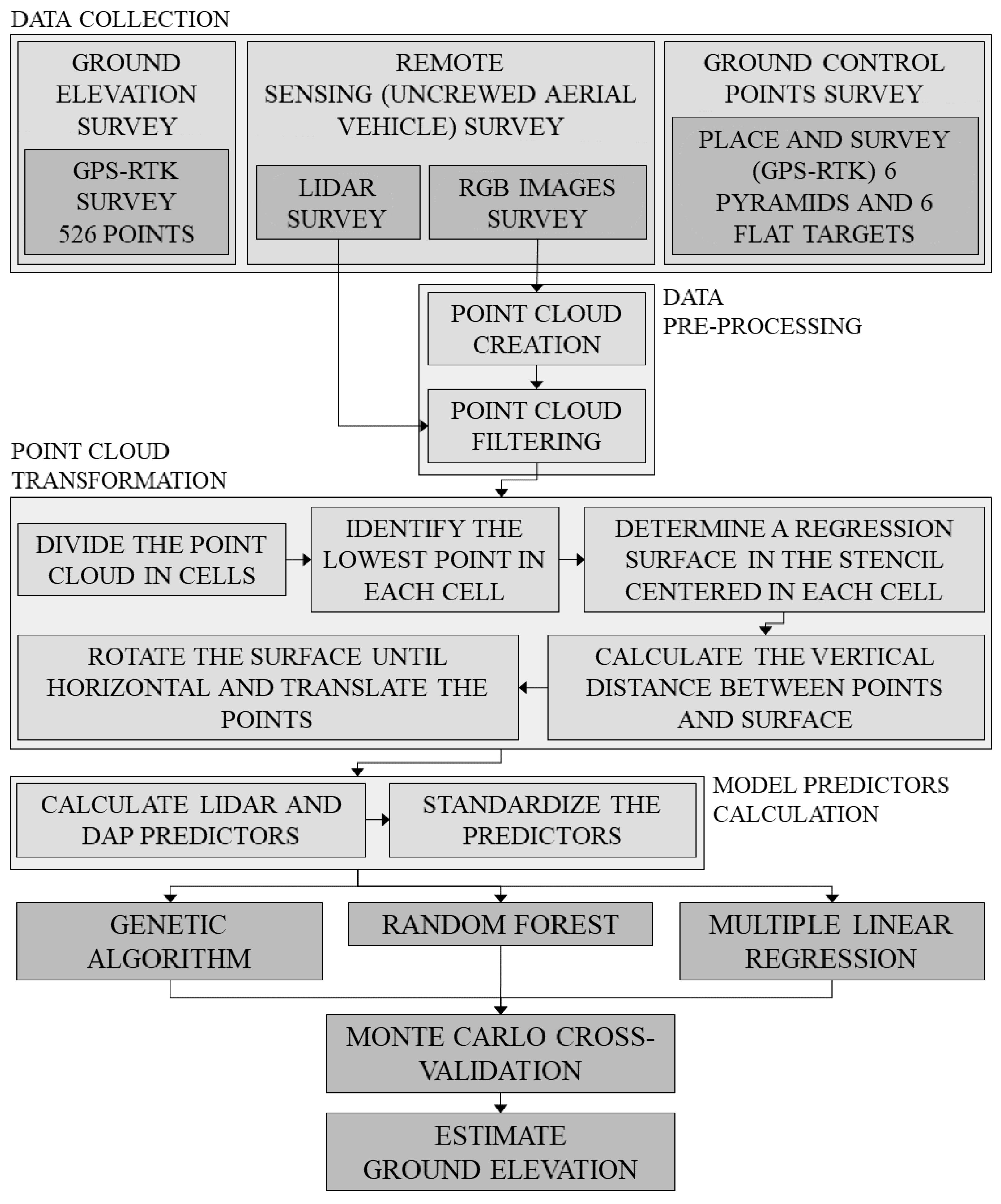
Our procedure consists of the following steps (reported in Figure 1):
STEP 1.
We performed a ground elevation survey on the field, by using a GNSS rover, to collect ground-truth data over our study domain (Section 2.2).
STEP 2.
We used a UAS to collect a high-resolution LIDAR point cloud and high-resolution RGB images over our study domain (Section 2.3). We then calculated a DAP point cloud from the high-resolution images.
STEP 3.
We transformed the UAV–LIDAR and UAV–DAP point clouds by using the method developed by [21] to remove the effect of the ground slope on the ground elevation estimate (Section 2.4.2).
STEP 4.
We trained and tested three different regression techniques, a multiple linear regression, a genetic algorithm, and a random forest, to estimate the ground elevation from the transformed and the original point cloud (Section 2.6). To train and test each technique, we performed a Monte Carlo cross-validation.

2.1. Study Site

The study domain is a ~0.5 km2 coastal back dune environment located at Topsail Hill Preserve State Park (THPSP), located in Santa Rosa Beach, FL, USA (Figure 2). The study domain is located southeast of Morris Lake and extends from the shoreline to the local coastal forest (Figure 2b).
THPSP contains two large coastal dune lakes: Morris Lake and Campbell Lake. These lakes are a rare environment because they exchange water with a salty waterbody [39]. The lakes are connected to the Gulf of Mexico through channels, which close off in dryer periods, and frequently change in appearance as the water creates new paths to the Gulf. In THPSP, water preferentially flows from the lakes to the Gulf of Mexico (i.e., outward, ibid.). However, specific wind conditions and tides invert the flow from the Gulf into the lakes (i.e., inward, ibid.).
THPSP is a unique brackish environment, which provides a habitat for a wide range of imperiled plant and animal species. This environment houses four subspecies of imperiled beach mice, three of which are endemic to the Florida Panhandle [40]. In addition, the dunes provide a habitat for the gopher tortoise (Gopherus polyphemus), as well as a nesting area for two rare shorebirds: the snowy plover (Charadrius alexandrines) and Wilson’s plover (Charadrius wilsonia, ibid.). Finally, the milkweed (Asclepias humistrata, ibid.) that grows on the dunes is a key plant for the reproduction of migrating monarch butterflies (Danaus plexippus, ibid.).
Apart from its ecological role, vegetation significantly affects the ability to map the area with remote sensing techniques. For example, it is documented that the ability to monitor exposed dunes in THPSP with remote sensing techniques is inhibited by plants growing on them, such as Gulf coast lupine (Lupinus westianus, ibid.).

2.2. Field Measurements

To perform the ground elevation survey, a plastic-capped iron rod was placed at the center of the survey area to serve as a semi-permanent monument. The Zephyr 3 base station was set up over this point and two Zephyr 3 GNSS rover units were used to collect checkpoints throughout the survey area. The expected accuracy is approximately 2 cm (RMSE). Measurements with the GNSS rovers were made using an observation time of 5 s. Results were processed using the projected coordinate system NAD 1983 UTM zone 16N.
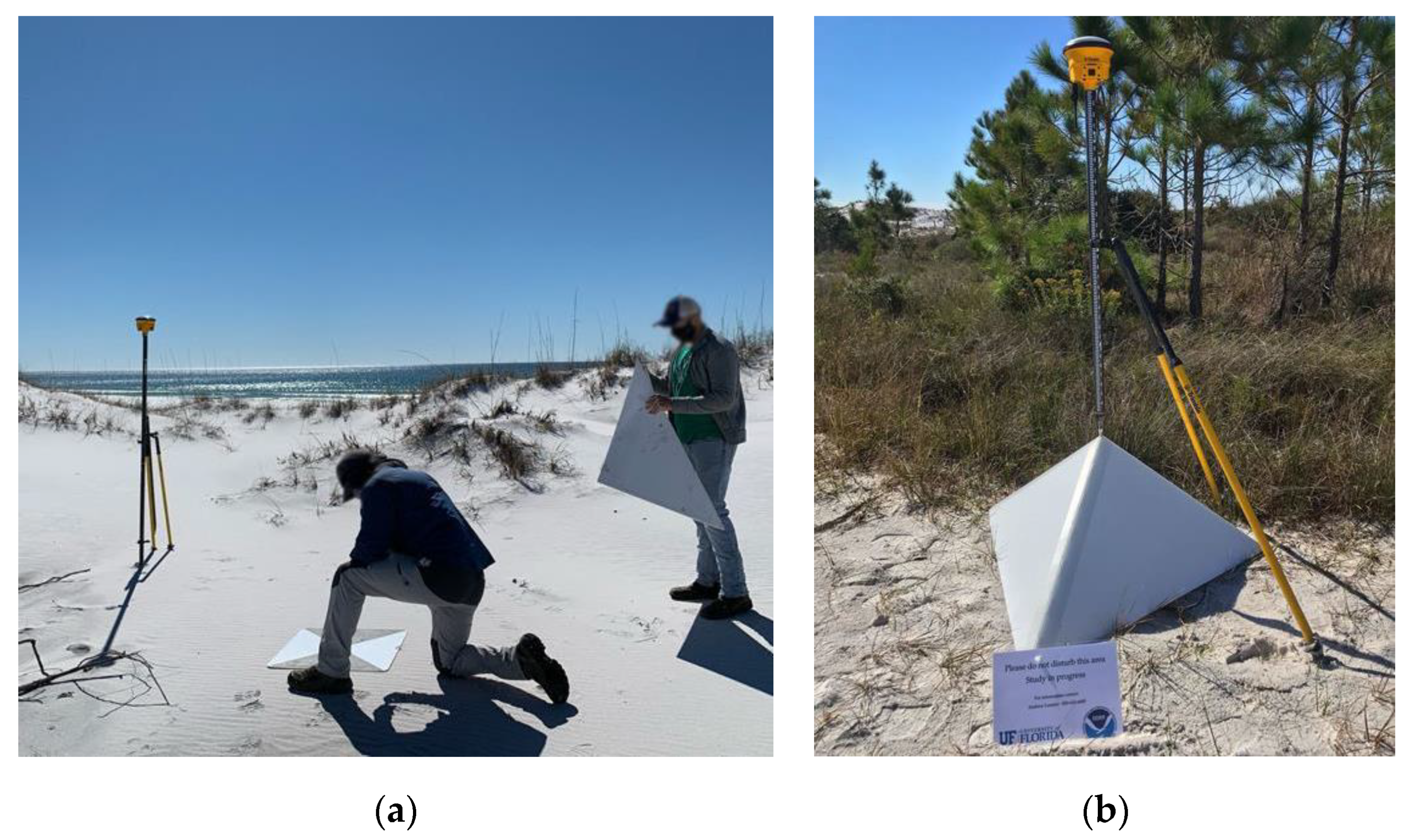
The complete survey included 526 checkpoints, 12 GCPs for the UAS survey (see Section 2.3), and the location of the base station (light blue, orange, and violet markers, respectively, in Figure 2b). The checkpoints were distributed in the study area to obtain measurements among different slopes and vegetation covers. Ground control points (GCP) were placed along two cross-shore transects separated by a longshore distance of ~500 m. Along each transect, pairs of GCP targets which consist of 1 flat target (Figure 3a) and 1 pyramidal target (Figure 3b), were set in three locations.

2.3. Remote Sensing Measurements

The UAS data collection was conducted using a Phoenix LIDAR Systems Scout-32 (Phoenix LiDAR System, Austin, TX, USA), which is a lightweight system that collects data at a range of up to 65 m. This system allows for the combination of multiple sensors, including a laser scanner and a variety of camera systems. For this collection, a Sony Alpha ILCE–A6000 CMOS (Sony Group Corp, Tokyo, Japan) was utilized in combination with the Velodyne HDL-32E laser scanner (Velodyne Lidar, San Jose, CA, USA). The Sony Alpha ILCE-A6000 is a 24-megapixel RGB camera with a complementary metal–oxide conductor sensor (CMOS). The Velodyne HDL-32E consists of 32 individual laser range finders which cover a field of view of 41.33 degrees parallel to the flight direction. The entire array of laser range finders continuously rotates providing a 360-degree field of view perpendicular to the flight direction. Each beam has a horizontal divergence of 2.79 mrad and a vertical beam divergence of 1.395 mrad resulting in a beam footprint of 8.3 cm × 4.1 cm at a range of 25 m. Each laser range finder can measure up to 2 returns per outgoing pulse, however, dual returns are registered only for objects separated by at least 1 m. The sensor can measure approximately 700,000 returns per second when operating in single-return mode. To collect our data, we used a flight altitude of 30 m and a line spacing of 25 m, respectively.

2.3.1. LIDAR Dataset

The UAV-LIDAR point cloud collected by using the Velodyne HDL-32E has an average density of ~1600 points m−2. The geographic coordinates and the elevation of the points are assigned in the NAD 1983 UTM 16N geodetic system, and the WGS84 ellipsoid, respectively. The point cloud was adjusted by applying the procedure proposed in [41] to the GCPs. The resulting residual in the target (GCPs) coordinates was ~1 cm.

2.3.2. Imagery Dataset

The Sony Alpha ILCE-A6000 CMOS camera was used to collect high-resolution images of the study area. The area contained in the RGB images is slightly smaller than the one surveyed for the LIDAR point cloud. The camera collected images from a nadir perspective, at the highest resolution (6000 × 4000 pixels), with a 3:2 aspect ratio. Images have a footprint of 45 m × 32 m, and an average overlap of 60%. We used the high-resolution RGB images as input for the Pix4DMapper software (Release 4.8.0, Pix4D, Prilly, Switzerland), to obtain a DAP point cloud. To georectify the images, the software uses a semi-automated approach, which requires manual identification of the GCPs in the input images. Thus, we identified the midpoint of each GCP in different groups of at least six images. The output DAP point cloud has an average point density of ~1200 points m−2. The geographic coordinates and the elevation of the points are assigned in the NAD 1983 UTM 16N geodetic system, and the WGS84 ellipsoid, respectively. We compared the coordinates of the pyramidal GCPs centroids on the point cloud, with the corresponding values we surveyed in the field (see Section 2.2). We obtained a horizontal and vertical georeferencing error of 2.8 ± 0.8 cm (mean absolute error ± root mean square error, M A E   ±   R M S E ) and 3.2 ± 1.0 cm, respectively.

2.4. Ground Elevation Estimation

2.4.1. Point Clouds Filtering

We filtered both UAV-LIDAR and UAV–DAP point clouds by removing: (i) the points collected outside the study domain (red line in Figure 2); (ii) the points which elevation is lower than 2 m below MSL; and (iii) the points whose elevation is higher than 20 m above MSL in the area occupied by the freshwater forest and 8 m above MSL along the coastline.

2.4.2. Point Cloud Transformation and Sloping Ground

In this study, we transform the UAV–LIDAR and UAV–DAP point clouds by applying the MATLAB algorithm proposed in [21] to remove the effect of ground slope on the ground elevation estimate. The algorithm workflow is described in the Supplementary Materials. In this section instead, we report only some relevant background from [21].
The algorithm proposed in [21] improves the estimate of ground elevation extracted from point clouds when the ground is sloping. Many approaches can be used to estimate the ground elevation distribution from a point cloud. Some of them use a classifier to distinguish between ground and non-ground points and then use the ground points to create a TIN surface that describes the ground elevation. Other methods are based on regular grids, in which the ground elevation is calculated for each cell as the minimum elevation of the point cloud contained in it, and assigned to the entire cell surface, or the cell center. For the latter, cell size must be large enough so that the chance that at least one of the points in the area describes the ground is sufficiently high and small enough so that the minimum elevation reasonably represents the elevation at its center. In addition, note that the survey points are not located at the center of a cell in the grid used to describe our study area. For this reason, their elevation was estimated by performing a bilinear interpolation on the elevation of the four cell centers surrounding each of the surveyed points. When tested on the 526 points we collected in the study area, we observed that the optimal average cell size corresponds to 30 cm for the point clouds.
For sloping ground, a point located in a less elevated region can be taken as the minimum and assigned to the cell center, producing large errors. To avoid this problem, the algorithm uses the point cloud contained in a 3 × 3 cells stencil ( S T n , e ), centered in the considered cell (n,e), to estimate an approximation of the ground surface. This approximation is defined using a regression plane, or polynomial surface, based on the minimum elevations identified in the 9 cells constituting the stencil. The algorithm uses this approximation to transform a sloping-ground case into a flat-ground case (see Supplementary Materials). In this study, cells are square and have a dimension of 30 cm × 30 cm.
The algorithm was applied to the UAV–LIDAR and UAV–DAP point clouds. The bed elevations were obtained from the techniques described in the next section, which use as inputs the predictors we calculated from the transformed and non-transformed point clouds, as described in Section 2.4.3.

2.4.3. Model Predictors

This section summarizes the model predictors we computed by using the UAV–LIDAR and UAV–DAP point clouds in S T n , e . Each predictor was calculated for the non-transformed point clouds, as well as for the point clouds transformed using the planar and the polynomial regressions proposed in [21] (see Supplementary Materials). For readability, hereafter, we use the subscript “n,e” to indicate the variables related to the stencil S T n , e .
The model predictors are:
  • The number of points of the point cloud contained in S T n , e , M n , e .
  • The maximum elevation of the points in S T n , e , z n , e m a x :
z n , e m a x = max   s S T n , e z s ,
where z s is the elevation of the s t h point of the point cloud in S T n , e .
  • The minimum elevation of the points in S T n , e , z n , e m i n :
z n , e m i n = min   s S T n , e z s .
  • The elevation range of the points in S T n , e , z n , e :
z n , e = z n , e m a x z n , e m i n .
  • The mean elevation of the points in S T n , e , z n , e m e a n :
z n , e m e a n = s S T n , e z s M n , e .
  • The mean elevation range of the points in S T n , e , z n , e m e a n :
z n , e m e a n = z n , e m e a n z n , e m i n .
  • The standard deviation of the elevation of the points in S T n , e , σ n , e :
σ n , e = s S T n , e z s z n , e m e a n 2 M n , e 1 .
  • The skewness of the elevation of the points in S T n , e , S n , e :
S n , e = 1 M n , e s S T n , e z s z n , e m e a n 3 1 M n , e s S T n , e z s z n , e m e a n 2 3 / 2 .
  • The kurtosis of the elevation of the points in S T n , e , K n , e :
K n , e = 1 M n , e s S T n , e z s z n , e m e a n 4 1 M n , e s S T n , e z s z n , e m e a n 2 2 .
  • The mode elevation of the points in S T n , e , z n , e m o d e . To calculate it, we divided the point cloud into six equivalent vertical layers, and we identified the mode as the average elevation of the layer containing the highest number of points.
  • The median elevation of the points in S T n , e , z n , e m e d i a n . The value separates the higher and the lower halves of the points in S T n , e . The value is unique if M n , e is an odd number. For even M n , e , there are two middle elevation values. We consider z n , e m e d i a n equal to their average.
  • The ground slope in S T n , e , S l o p e n , e . The value is calculated as the maximum slope of the regression plane based on the minimum elevations identified in the 9 cells constituting the S T n , e (see Section 2.4.2 and Supplementary Materials).
The predictors are reported in Table 1.
Finally, we standardized each predictor P using the following procedure:
P ^ = P P ¯ S D P   ,
where P ^ , P ¯ , and S D P are the standardized, the average, and the standard deviation value of the predictor P , respectively.

2.5. Regression Techniques

In the following sections, we describe the regression techniques we used in this study to estimate ground elevation from the UAV–LIDAR, and UAV–DAP transformed and non-transformed point clouds, by using the predictors reported in Section 2.4.3. All regression techniques were implemented in MATLAB (release R2020b, MathWorks, Natick, MA, USA). The results obtained from each regression technique and point cloud will be compared by using the error metrics described in Section 2.7.

2.5.1. Multiple Linear Regression

Multiple linear regression (MLR) is a statistical technique that uses multiple independent variables (i.e., predictors) to predict the outcome of a response (i.e., dependent) variable. These regressions are based on the following formula:
y v = β 0 + β i x v i + ϵ i = 1 , N v ,
where for each observation v, y v is the dependent variable, x v i is the i t h of the N v independent variables, β 0 is the intercept on the ordinate’s axis, β i is the slope coefficient associated to the i t h independent variable, and ϵ is the model error.
Since MLR can have different performances based on the number of predictors used in the regression, we applied the regression to all the possible combinations of the predictors reported in Table 1. The analysis was performed for all the point cloud types (i.e., UAV–LIDAR and UAV–DAP), and transformations (i.e., non-transformed, transformed plane, and transformed polynomial). The total number of combinations we analyzed is then equal to 4095.

2.5.2. Genetic Algorithm

To calculate ground elevation at each cell (n,e), we used a regression model based on a genetic algorithm (GA). In the genetic algorithm, an initial population constituted of random entities changes until it reaches the optimal configuration, which resembles the configuration of a target population [42]. This procedure simulates a biological evolution process, where the population evolves over consecutive generational steps. The individuals composing each step are chosen from those constituting the previous step by using a fitness function, which is calibrated on the target population.
In this study, the individuals are the model predictors calculated from the UAV–LIDAR and UAV–DAP point clouds, which are described in Section 2.4.3 and are reported in Table 1. The fitness function used to change the population at each stage is a linear regression function, which is used by the algorithm to fit the input data and was calibrated using the R M S E . Finally, the target population is constituted of the GPS–RTK ground elevation points we collected in the study area.
Compared to traditional optimization algorithms, a genetic algorithm has many advantages [43,44], such as the possibility to be used with small datasets and to obtain as output an explicit equation for the ground elevation (i.e., our dependent variable) as a function of the model predictors. The formula can also be used to directly understand the relative importance of each predictor.

2.5.3. Random Forest Algorithm

To estimate the ground elevation in our study area, we also use a random forest (RF) regressor. A random forest is an ensemble-based machine-learning method that can be used for classification or regression problems. An ensemble method in machine learning employs multiple models to interpret given data and then combines the outcomes from each model to provide a result. In a random forest regressor, the model consists of a set of individual decision trees, operating as an ensemble. Given a dataset of labels (i.e., results, in our case, ground-truth elevation data collected in a survey) to use in the regression, each tree gives a prediction value to each label by using some regression features (i.e., the predictors). For each label, the average of the predictions produced by the trees is the prediction of the random forest regressor.
In this study, the dataset is constituted of the point clouds contained in each S T n , e . The regression features are the predictors calculated from the UAV–LIDAR and UAV–DAP point clouds, which are described in Section 2.4.3 and reported in Table 1. The predicted value is the ground elevation.
The model can be adjusted by determining the number of decision trees and the dimension of each tree [45]. The performances of a random forest model might depend on the number of decision trees. To verify this, we made a sensitivity analysis. In the analysis, we trained the RF using 80% of the ground elevation points surveyed in the study domain (i.e., the cross-validation dataset described in Section 2.6), and we tested it on the remaining 20% of the surveyed points (i.e., the test dataset described in Section 2.6). The results indicate that the performance of the RF increases with the number of trees until they reach a stable value after ~2000 trees. For this reason, we used this value in our study. Finally, note that a high number of trees can significantly increase the computational cost of the model. However, because of the limited dimension of our dataset and the meager number of variables we considered, even a high number of trees does not significantly increase the computational cost of the model.

2.6. Training, Validation, and Testing of the Regression Techniques

We trained and tested the multiple linear regression, the genetic algorithm, and the random forest models by using a Monte Carlo cross-validation on the dataset of 526 RTK–GPS points we collected in our study domain (Section 2.2). The dataset was divided into a cross-validation and a test dataset. They contain 416 and 110 entries, which correspond to ~80% and ~20%, of the entire dataset, respectively.
With the cross-validation dataset, we trained the algorithm using 333 entries (i.e., ~80%) randomly selected from the cross-validation dataset, we validated it on the remaining entries (i.e., ~20% of the cross-validation dataset), and we calculated the training and prediction errors. To perform the Monte Carlo cross-validation, we repeated this procedure 150 times (i.e., permutations). We then calculated the average training and validation error by averaging the errors obtained from each permutation, and we used them to verify the performances of the model during the training and validation steps. Once the model is validated, we tested it on the test dataset. Once the model is tested, we used the whole 526-entities dataset to determine the regression formulas and calculate the ground elevation. This procedure is performed for each model by using MATLAB.

2.7. Error Analysis

We quantified the error of the estimated ground elevation by using the M A E , the R M S E , and the coefficient of determination ( R 2 ). The considered model has good predictive skills if the value of M A E and R M S E are close to zero, and if the value of R 2 is close to 1. The value of the error metrics was calculated as follows:
M A E = i = 1 N y o y p r N ,
R M S E = i = 1 N y o y p r 2 N ,
R 2 = 1 i = 1 N y o y p r 2 i = 1 N y o y o ¯ 2 .
In Equations (11)–(13), yo and ypr are the observed and predicted quantities, respectively, in the i t h sampling location, and N is the dimension of the dataset.

3. Results

3.1. Effect of Predictors Subsets on MLR Performance

In this section, we present the results obtained by using different combinations of predictors for the MLR. For simplicity, the results are reported only for the test phase of the cross-validation. The same analysis, performed for the RF, indicated that the performance of this regression technique increased with the number of predictors considered. For this reason, in the following chapters, we report only the results obtained by using all the predictors in Table 1 as input of the RF. The analysis was not performed for the GA, since this regression technique automatically discards the predictors whose contribution to the ground elevation estimate is negligible.
Figure 4 shows the value of the error metrics (i.e., M A E and R M S E ), obtained by using a growing number of predictors, obtained from the UAV–LIDAR (Figure 4a,b) and UAV–DAP point (Figure 4c,d) clouds, for the MLR. The error reported on the x-axis is the minimum observed for all the combinations using that number of predictors.
The results of our analysis, reported in Figure 4, indicate that for all the point clouds (i.e., UAV–LIDAR, in Figure 4a,b and UAV–DAP, in Figure 4c,d), and transformations (i.e., non-transformed, transformed plane, and transformed polynomial surface, blue, orange and yellow lines in Figure 4, respectively), both M A E and R M S E decrease when the number of predictors used in the MLR increases from one to two to four. In most cases, both errors remain unchanged when the number of predictors grows up to eight to ten, and again remain unchanged, or slightly increase when the number of predictors reaches 12. Both M A E and R M S E strongly increase when the number of predictors changes from six to twelve, only when the UAV–DAP point cloud is transformed by using a regression plane. Note that these non-negligible increases are related to the transformed point clouds, which do not provide the lowest error metrics for the UAV–DAP technique. For this reason, and to make outcomes of MLR comparable to GA and RF, the results of MLR reported in the next sections will refer to the case when all the predictors are used in the regression.

3.2. Ground Elevation Estimate

In this section, we present the results obtained by using the multiple linear regression, the genetic algorithm, and the random forest methods, to estimate the ground elevation from the non-transformed UAV–LIDAR and UAV–DAP point clouds, and from the point clouds transformed by using a planar and a polynomial surface. For each regression technique, the errors ( M A E and R M S E ), and the R 2 we obtained from the Monte Carlo cross-validation and test phases are reported in Table 2. We want to stress that the evaluation metrics reported in the Train and Val columns of Table 2 are obtained by averaging those obtained from each permutation of the Monte Carlo cross-validation (see Section 2.6). The evaluation metrics reported in the Test column, instead, are those obtained by applying the validated models on the test dataset (see Section 2.6).
For all the regression techniques (rows), and at each stage of the Monte Carlo cross-validation (columns), we observed a reduction in M A E and R M S E when the UAV–LIDAR point cloud is transformed by using a regression plane (second column). This transformation reduces the errors obtained by using the original point cloud, by ~10% for the MLR, ~30% for the GA, and ~12%, for the RF, on average. Note that errors reduce by comparable percentages in each phase of the cross-validation, except for the MLR, where the reduction observed in the test phase is half of those observed in the training and validation phases. The transformation based on a polynomial surface gives a smaller reduction, or in some cases, an increase in M A E and R M S E , compared to the cases where the original point cloud is used. This transformation reduces both errors by ~20% for the GA, and by ~5% for RF, on average, and increases them by ~10% for MLR.
For the UAV–LIDAR point cloud, the MLR and the GA show comparable values of M A E and R M S E when the point cloud is transformed using either a regression plane or a polynomial surface. In particular, the difference does not exceed 10% in most of the cross-validation steps. When the point cloud is not transformed, instead, the MLR gives smaller errors than the GA. Independently on the point cloud transformation, the errors obtained for MLR and GA are ~40% lower, on average, than those observed for RF.
We obtained the lowest errors by applying the GA to the point cloud transformed using a regression plane (second row and column in Table 2). For this case, the M A E and R M S E are equal to ~6.80 cm and ~9.80 cm, respectively, for the training and validation steps, and grow to 7.64 cm and 9.86 cm in the test phase. The scenario where the MLR is applied to the point cloud transformed by using a regression plane (first row and second column in Table 2) instead, shows slightly higher errors. For this case, the M A E and R M S E are equal to ~7.00 cm and ~9.50 cm, respectively, during the training and validation steps, and grow to 7.78 cm and 13.19 cm in the test phase. For the same point cloud, the RF gives a higher value of M A E and R M S E , which are equal to ~10.00 cm and ~17.25 cm, respectively, in all the phases of the cross-validation.
According to M A E and R M S E , Table 2 shows that the highest values of R 2 are obtained when the MLR and GA are applied to the point cloud transformed using a regression plane. These two cases show comparable R 2 values, equal to ~0.995 for the training and validation phases, and ~0.990 for the test phase of the cross-validation (second column in Table 2). Again, for MLR and GA, R 2 slightly decreases to ~0.992 for the training and validation phases and ~0.975 for the test phase, when the point cloud is either transformed using a polynomial surface (third column in Table 2) or is not transformed (first column in Table 2). Finally, RF shows the lowest values of R 2 , since, for all the point clouds, it is smaller than 0.982 (third row in Table 2).
For the UAV–DAP point cloud, M A E and R M S E computed with the non-transformed point cloud are lower than the ones computed with any of the transformed point clouds. This is true for each cross-validation phase (i.e., training, validation, and test) and point regression technique (i.e., MLR, GA, and RF). The only exception is the training phase of MLR when the point cloud is transformed using a regression plane. In this case, both M A E and R M S E reduce by ~1%, with respect to the same case using the non-transformed point cloud. In all the remaining cases the errors increase up to ~650%.
For the non-transformed UAV–DAP point cloud (first column in Table 2), RF shows the lowest errors, independently on the phase of the cross-validation (sixth row, first column in Table 2). M A E and R M S E go from 21.71 cm and 30.79 cm, respectively, in the validation phase, to 24.99 cm and 35.30 cm, in the test phase. For MLR instead, M A E and R M S E go from ~21 cm and ~30 cm, respectively, in the training and validation phases, to 27.08 cm and 40.56 cm, in the test phase (fourth row, first column in Table 2). Finally, for the GA, the value of M A E and R M S E go from ~25 cm and ~35 cm, respectively, in the training and validation phases, to 33.54 cm and 46.49 cm, in the test phase (fifth row, first column in Table 2). According to M A E and R M S E , the highest R 2 values are observed for RF, and are equal to 0.944 and 0.920, for the validation and test phase, respectively. For MLR and GA, R 2 is generally higher than 0.915 in the training and validation phases but decreases to 0.894, for MLR, and 0.861, for GA, in the test phase.

3.3. Regression Formulas to Estimate Ground Elevation

After the model was validated, we used the entire 526-entities dataset, related to the UAV–LIDAR point cloud transformed using a regression plane, and to the non-transformed UAV–DAP point cloud, to train the MLR, GA, and RF models. We chose these point clouds because they obtained the best results in cross-validation, as reported in Section 3.1, and Table 2.
For the MLR and GA, applied to the UAV–LIDAR point cloud, we obtained the following relationships to estimate the ground elevation ( z n , e ) in the 30 cm × 30 cm cells describing our study area:
z ^ n , e = 0.034   σ ^ n , e   0.009   S ^ n , e + 0.920   z ^ n , e m i n + 0.018   z ^ n , e   0.065   z ^ n , e m e a n + 0.006   z ^ n , e m o d e + 0.068   z ^ n , e m e d i a n +   0.003   K ^ n , e + 0.032   S l o p e ^ n , e ,
z ^ n , e = 0.996   z ^ n , e m i n .
For the MLR and GA, applied to the UAV–DAP point cloud instead, we obtained the following relationships, to estimate the ground elevation in the cells:
z ^ n , e = 0.353   σ ^ n , e +   0.012   S ^ n , e + 1.543   z ^ n , e m i n 0.311   z ^ n , e +   0.236   z ^ n , e m e a n + 0.327   z ^ n , e m o d e 0.935   z ^ n , e m e d i a n +   0.034   K ^ n , e 0.008   S l o p e ^ n , e ,
z ^ n , e = 0.956   z ^ n , e m i n .
Equations (14)–(17) are based on the predictors reported in Table 1.

3.4. Ground Elevation Maps

In this section, we report the ground elevation maps obtained by applying the multiple linear regression (Figure 5a,b), the genetic algorithm (Figure 5c,d), and the random forest (Figure 5e,f) methods to the UAV–LIDAR point cloud transformed using the regression plane method proposed by [21] (first column in Figure 5), and to the non-transformed UAV–DAP point cloud (second column in Figure 5). Note that the ground elevation estimates obtained from the UAV–DAP point cloud cover only the part of the entire study domain where we collected the RGB images, as explained in Section 2.3.2.

4. Discussion

4.1. High-Resolution MAPS

The high-resolution maps reported in Figure 5 are used to visualize and compare the ground elevation obtained by applying different regression techniques to the UAV–LIDAR (first column) and UAV–DAP (second column) point clouds collected in a coastal environment. We can distinguish the local infrastructures (purple lines in Figure 6a), i.e., some dirt roads and a wooden bridge, from the surrounding natural habitat. We can also distinguish between dry areas and wet areas. The latter consist of the shore, the swash zone, and the central creek that connects the Gulf of Mexico to Morris Lake. Among the dry areas, we can distinguish four different elements: (i) the incipient dunes (green areas in Figure 6a), located at the high spring tide mark. (ii) The established dunes (black areas in Figure 6a) that run parallel to the shoreline are placed behind the incipient dunes. (iii) The backdune environment comprises wetlands and secondary dunes (magenta areas in Figure 6a). These dunes result from the progressive modification of past established dunes and are either unvegetated or occupied by shrubs and bushes. (iv) The hinterland is the high-elevation area placed behind the backdune environment. This area is protected from seawater and occupied by long-lived vegetation, such as high trees and coastal shrubs.
All the ground elevation maps in Figure 5 indicate the presence of a continuous incipient dune that runs parallel to the shoreline. Its path is interrupted only by the central creek. This incipient dune has an almost constant crest elevation of 2–3 m MSL, which correspond to a height of 1–2 m above the surrounding area [46]. According to all the datasets and regressions, the incipient dune reaches its maximum elevation, equal to ~3–4 m MSL in the western portion of the domain due to the proximity of an established dune.
The ground elevation maps in Figure 5 show that the established (or principal) dunes are identified in the study area, by every point cloud dataset and regression technique considered in this analysis. Eight principal dunes are identified in our study area. They are divided into two groups of five and three dunes, respectively, located on the western and eastern sides of the creek carving the marsh at the center of our study domain. The results obtained from the GA and MLR applied to the transformed UAV–LIDAR point cloud and the non-transformed UAV–DAP point cloud indicate that the crest elevation of the established dunes is between 6 and 10 m above MSL (Figure 5a,c, and black areas and circles in Figure 6a,b). When the RF is applied to the transformed UAV–LIDAR and UAV–DAP point clouds instead, the results indicate that the established dunes are not higher than 7 m MSL at their top (Figure 5b,d–f). This depends on the fact that the range of predictions the RF regressor can make is constrained by the highest and lowest labels in the training data [47]. Since none of the surveyed points has an elevation higher than 7.5 m MSL, the estimated ground elevation is always lower than this value. Major differences in the predicted elevation potentially lead to major differences in the evaluation of coastal dunes evolution, in the case the proposed methods, are used for this analysis. For this reason, the choice of the most accurate methods, such as the GA and the MLR applied to the UAV–LIDAR point cloud, should be performed to perform them.
The ground elevation maps in Figure 5 indicate that the backdune environment is different in the western and eastern portions of the study domain. In the western portion of the domain, the backdune environment is occupied by isolated, or partially connected secondary dunes, which elevation at the crest is equal to ~3–5 m MSL (Figure 6b) and reaches ~5–6 m MSL in just two dunes. Close to Morris Lake, a low elevated wetland constitutes the backdune environment. Note that, compared to the UAV–LIDAR point cloud, the results obtained from the UAV–DAP point cloud indicate that large depressions (i.e., the areas whose elevation is below MSL, purple areas in Figure 5) are in this part of the domain. However, a comparison with the local USGS maps, and the airborne LIDAR in the NOAA inventory (https://coast.noaa.gov/dataviewer/#/, accessed on 5 March 2022), suggests that the results are not correct, and thus the absence of these depressions. The error is probably due to the absence of GCPs in this peripheral location of the study area, and thus to the inaccurate georectification of the images we collected there, or to image-matching errors associated with water and/or vegetation types in those areas. These results indicate that LIDAR techniques should be preferred to DAP techniques to survey these areas because of their lower sensitivity to dense vegetation, bright surfaces, and homogeneous areas [34,37]. In the eastern part of the domain instead, the backdune environment is mostly flat. Only a few small (i.e., 4 m MSL elevation) secondary dunes are visible in the ground elevation maps obtained from both the UAV–LIDAR and UAV–DAP and reported in Figure 5.
In Figure 5, the hinterland area is described only in the ground elevation maps obtained from the UAV–LIDAR point cloud. In these maps, the northern area of the study domain is occupied by a small hill (blue area in Figure 6a), which elevation at the crest is higher than 15 m MSL, according to the MLR and GA, and is not higher than 10 m MSL, according to the RF. Note that, differently from the MLR and GA maps, in the RF map the ground elevation values in the hinterland hill are noisy, and the noise distribution resembles the distribution of the trees that grow on the hill. This result suggests that high vegetation affects more RF than GA and MLR. Because none of the GPS points that were surveyed in the hinterland area has an elevation higher than 7.5 m MSL, RF is unable to correctly estimate the ground elevation for high ground [47]. GA, instead, uses only the minimum elevation of the local point cloud to calculate the ground elevation in the study area (see Equations (15) and (17)). Equations (15) and (17) indicate that z ^ n , e is calculated by reducing the value of z ^ n , e m i n . This is performed to remedy the overestimation of the elevation of the points surveyed by using both UAV–LIDAR and UAV–DAP techniques due to the presence of vegetation in many areas of the domain. Thus, for GA, the ground level estimate does not depend on the range of the ground elevation values collected in the field survey. They depend on the accuracy of the point cloud to which Equations (15) and (17) are applied, and on the capability of the chosen remote sensing survey method to collect data close to the ground, especially in vegetated areas. The same considerations are valid also for the MLR, since z ^ n , e m i n is the most important predictor in the estimate of ground elevation (see Equations (14) and (16)). For these reasons, GA or MLR should be preferred to RF to estimate ground elevation in highly vegetated areas. In addition, the use of LIDAR approaches should be preferred to photogrammetric ones, since in these highly vegetated areas, ground elevation was estimated only from the UAV–LIDAR point cloud.
From the spatial distribution of the ground elevation reported in Figure 5, we observed that the central creek, which connects the Gulf of Mexico to Morris Lake, is identified by any point cloud with any of the three proposed regression techniques. However, Figure 5 shows that the most accurate description of the creek is achieved by applying the MLR (Figure 5, first row) and GA (Figure 5, second row) to either the UAV–LIDAR or UAV–DAP point clouds. The RF instead (Figure 5, last row), does not successfully identify the creek, especially at the mouth, in the southern part of the domain. In addition, note that the central part of the creek is not identified by all the survey techniques (i.e., UAV–LIDAR and UAV–DAP), and regression methods (i.e., RF, GA, and MLR). For the UAV–LIDAR dataset, the thick water layer in the creek reduces laser pulse penetration and consequently impedes the return of that pulse from these areas to the laser scanner. For the UAV–DAP dataset, this can be due to the brightness of the water surface in the creek, which limits the identification of keypoints, and, consequently, the correct georectification of the images.
Finally, three dirt roads are visible in the spatial distribution of the ground elevation reported in Figure 5. For simplicity, their path is reported in Figure 6a using a purple line. One road starts in the north-western boundary of the domain and continues for about 200 m eastward in the domain area. The remaining two start at the northern boundary of the domain. One of them continues southward, in the eastern portion of the domain, crosses the hinterland hill and reaches the established dune close to the shoreline. The other one flanks the hinterland hill, then continues in the western portion of the domain, and finally reaches the secondary dunes.

4.2. Ground Elevation Estimates

The equations reported in Section 3.2 are used to compare the performances of UAV–LIDAR and UAV–DAP point clouds and different regression techniques in the estimate of ground elevation in a coastal environment.
Equations (14) and (16) highlight that z n , e m i n is the most important predictor we used to estimate ground elevation, since it has the highest coefficient, equal to 0.920 and 1.543, respectively. The significance of the other predictors in the estimate of ground elevation is different in the two equations. In Equation (14), the coefficients related to the other predictors are lower than 0.10, indicating that they are used to adjust the small errors in the ground elevation estimated by using z n , e m i n . According to Equation (14), z ^ n , e m i n has the maximum importance in the estimate of the ground elevation also in Equation (16). However, in Equation (16), the importance of the other predictors is not negligible. The most important predictor is z ^ n , e m i n , whose coefficient is 1.543, followed by z ^ n , e m e d i a n , σ ^ n , e , z ^ n , e m o d e , z ^ n , e , and z ^ n , e m e a n , whose coefficients are equal to 0.935, 0.353, 0.327, 0.311, and 0.236, respectively. The coefficients of the remaining predictors are lower than 0.10.
In Equations (15) and (17), z n , e m i n is the only predictor used to calculate ground elevation. The errors obtained by using these formulas, reported in Table 2, confirm the importance of z n , e m i n in the estimate of ground elevation. The coefficients of z ^ n , e m i n are equal to 0.996 and 0.956 in Equations (15) and (17), respectively. This means that the minimum elevation of the points collected in a cell ( z n , e m i n ) is subject to a minimal modification (i.e., it is reduced by 0.4% and 4.4%, respectively), and then used to calculate the ground elevation. The coefficients also indicate the overestimation error obtained by using the UAV–DAP point cloud is larger than the one obtained by using the UAV–LIDAR point cloud.
In addition, we underline that the results reported in Table 2 show that the removal of the ground slope from the UAV–LIDAR point cloud, by using a regression plane, increases the accuracy of the ground elevation estimate. Table 2 also indicates that an increase in ground elevation estimate accuracy is not obtained by transforming the UAV–DAP point cloud, because the slope obtained from this point cloud is less accurate than the one obtained from the UAV–LIDAR point cloud. The reason is the presence of large homogeneous and bright surfaces in the study area, which limit image matching and georectification [34,37], and the presence of vegetation areas, which limit the identification of points at the ground level.
The scatter plots reported in Figure 7 confirm that the ground elevation estimated using the UAV–LIDAR point cloud (first row) is more accurate than the one obtained using the UAV–DAP point cloud (second row) for each regression technique (columns). Another important source of error for the UAV–DAP point cloud, according to the literature [20,21], is the presence of dense vegetation and the inability of DAP to collect the information below it. Note that, in Figure 6b,d,f, the areas of the hinterland hill where the ground elevation was not estimated or was incorrectly estimated, are those occupied by tall trees or dense shrubs, which limit the correct georectification of the RGB images. Additionally, note that, in Figure 6b,d,f, the mainland areas whose elevation is below MSL (i.e., where the ground elevation was underestimated) are those far from the center of the study area. In those points, the georectification error is higher due to the distance from the GCP and due to the presence of dense and homogeneous shrubs. Large homogeneous surfaces in the study area limit image georectification [34,37]. However, in our study, the domain is mostly dotted by small vegetation patches or bushes, which facilitate image matching. Additionally, bright surfaces hamper image matching and georectification [34]. In our study area, these surfaces are the Gulf of Mexico in the south, Morris Lake in the north-west, the channel which connects them, and the areas they wet, such as the shoreline and the wetland adjacent to Morris Lake, which was partially covered by water during the remote sensing survey. Since the major differences in ground elevation estimates obtained from the LIDAR and the DAP datasets are observed in those bright areas (Figure 5, left column vs. right column), we assume that these errors are due to the incorrect image matching and georectification.
Figure 7d–f indicate that using the UAV–DAP point cloud RF produces estimation errors larger than those obtained by using the MLR and comparable to those obtained from the GA. The results in Figure 8 confirm this assumption for the UAV–DAP and indicate that the ground elevation is mostly underpredicted by the RF (Figure 8f), overpredicted by the GA (Figure 8d), and is equally underpredicted and overpredicted by the MLR (Figure 8b). Figure 7a–c indicate that errors obtained from the UAV–LIDAR point cloud are low, and comparable for all the regression techniques (columns).
In addition, Figure 8 indicates that the UAV–LIDAR point clouds give lower estimation errors than the UAV–DAP point cloud. While the error obtained from the UAV–LIDAR point cloud range between −0.5 m and +0.5 m, with a limited number of higher errors (in absolute value), the range of the errors obtained from the UAV–DAP point cloud is between −10 m and +10 m. In addition, both Figure 7 and Figure 8 indicate that MLR mostly shows underprediction errors, GA mostly shows overprediction errors, and RF shows no preference. Additionally, Figure 8 shows that, for the UAV–LIDAR point cloud (first column), the estimation error increases (in absolute value) in the proximity of vegetated areas. Finally, Figure 7c,f indicate that RF cannot be used to predict ground elevations higher than ~7.5 m MSL, as we previously explained.
Considering these results, Equations (15) and (17), and therefore the genetic algorithm, should be preferred to Equations (14) and (16), and therefore the multiple linear regression, to estimate ground elevation. This is because the latter equations require the computation of a larger number of predictors, compared to Equations (15) and (17), and because the equations obtained from the GA give smaller errors than those obtained from the MLR, as indicated in Table 2.
The absence of an equation provided by the Random Forest makes the application of this technique less immediate than the MLR and GA. In addition, because RF shows a higher sensitivity to the training dataset than the GA and the MLR, the use of these two latter regression techniques should be preferred.

5. Conclusions

In this study, we compared the results obtained by applying different regression techniques (i.e., multiple linear regression, genetic algorithm, and random forest), to a UAV–LIDAR and a UAV–DAP point cloud, to estimate the ground elevation in a coastal environment. The results are validated using a robust Monte Carlo cross-validation.
Our study is the first one that compares the performances of UAV–LIDAR and UAV–DAP point clouds when they are used to estimate topographic features in a coastal environment dominated by coastal dunes, and that reduces the error caused by a sloping terrain. Previous studies perform this comparison in forests, salt marshes, and grasslands, or use low-resolution point clouds, collected from aircraft and satellites. The results we obtained underline the pro and cons of UAV–LIDAR and UAV–DAP methods in this environment. Thus, this study can help both scientists and local managers to choose a survey method, depending on their budget and the desired quality of their results.
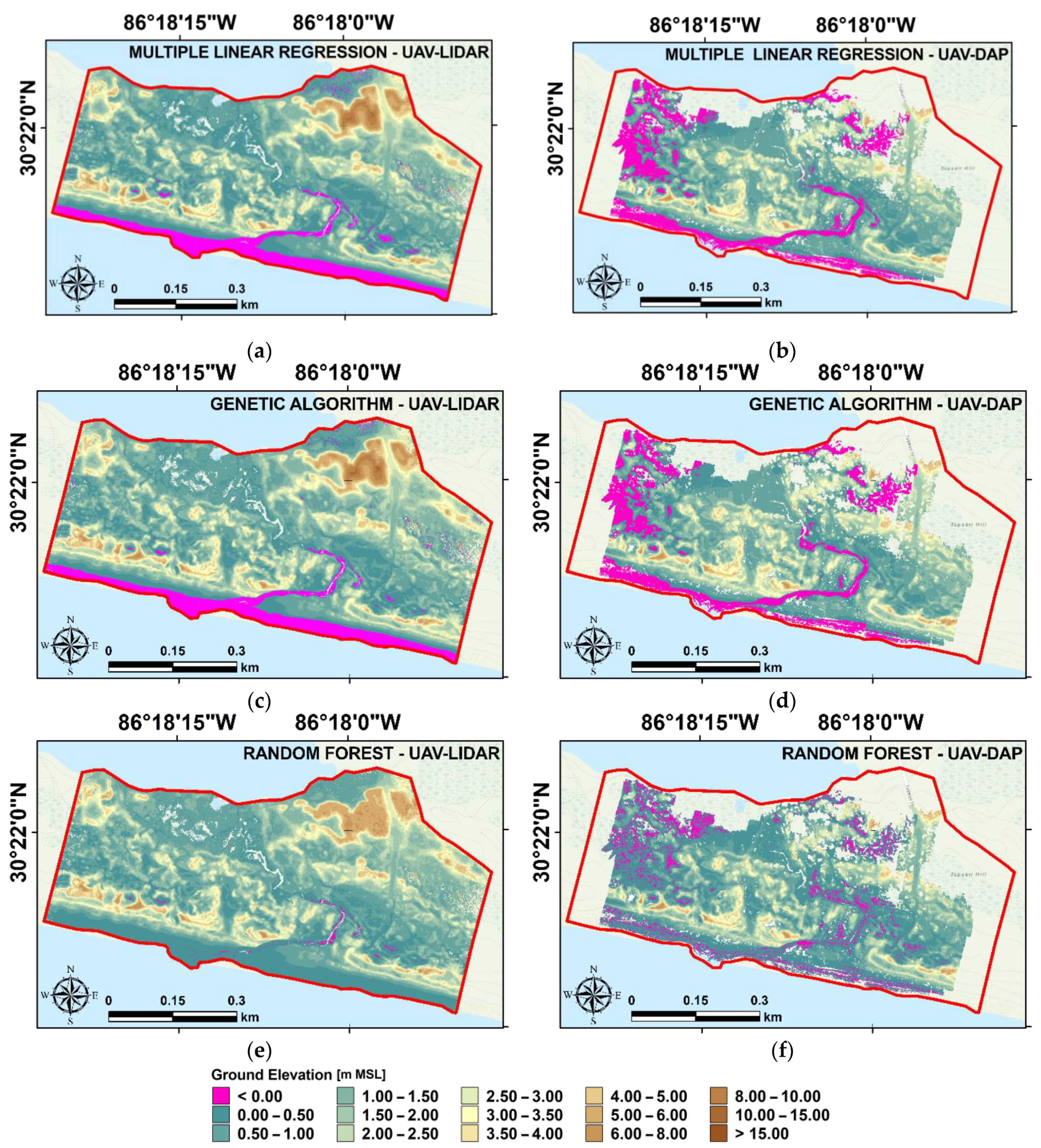
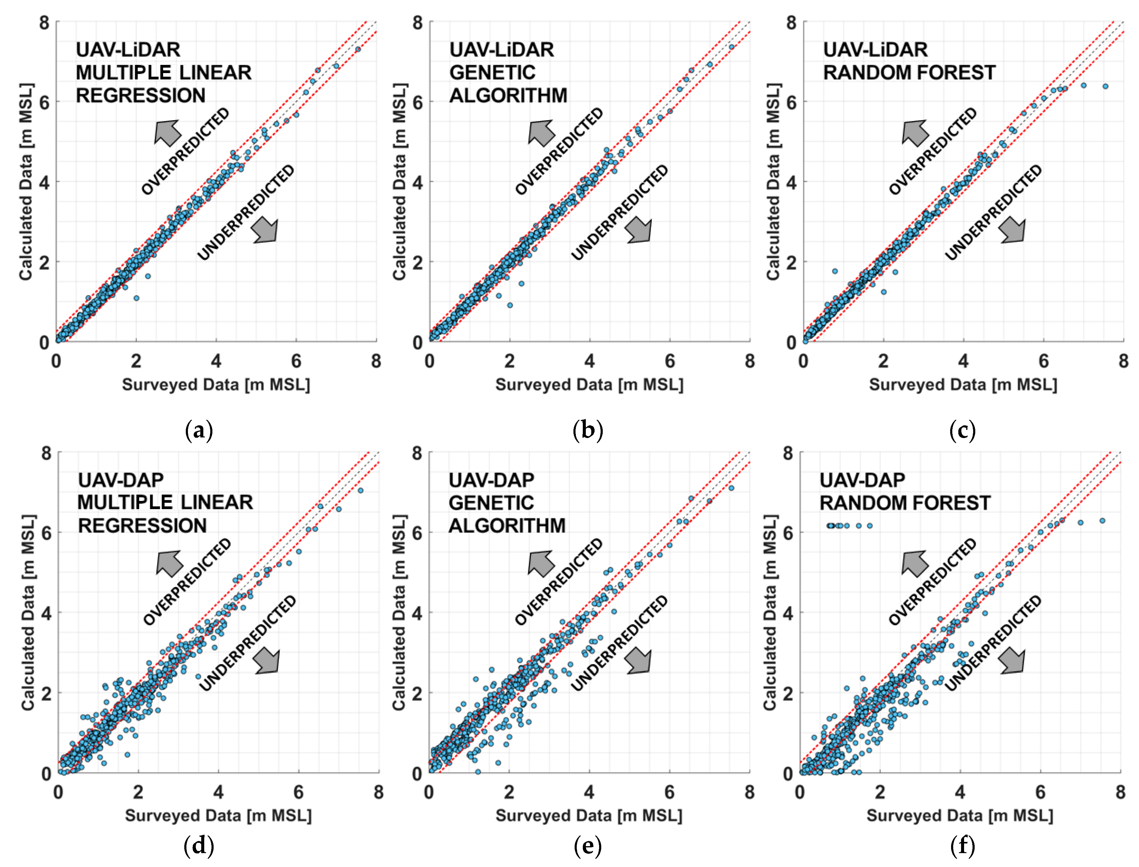
The results suggest that the UAV–LIDAR datasets should be preferred to the UAV–DAP datasets to estimate ground elevation in the considered coastal area. This is because of the lower estimation error obtained by using the LIDAR point cloud. The high estimation error obtained using the UAV–DAP point clouds is due to the limited capability of photogrammetry to acquire information below vegetation layers, and thus to the limited capability to determine elevation points close to the real ground level during the transformation of the imagery dataset in a appoint cloud.
Our study is also the first one comparing different regression techniques to estimate ground elevation in a coastal environment dominated by coastal dunes from high-resolution point clouds. The results suggest that optimal and similar results can be obtained from both the genetic algorithm and multiple linear regression, and that, for this reason, they should be preferred to random forest to estimate ground elevation. These results are independent of the point cloud (i.e., UAV–LIDAR or UAV–DAP) used to calculate ground elevation, and on the pre-processing geometric transformation performed on them.
To conclude, the results suggest that the most accurate description of ground elevation in our study area was obtained by applying the genetic algorithm to a point cloud transformed using a regression plane. For this reason, we suggest the use of this combination of techniques to describe the topography in similar coastal environments.
Future works will focus on the identification of the vegetation properties, such as height, density, and species, in the study area, by using a combination of imagery and LIDAR data. This will be beneficial to investigate the temporal and spatial modification of these properties. For example, the migration of the freshwater forest can be used as a proxy to estimate saltwater intrusion or the impact of SLR. Vegetation loss can also be used to estimate the impact of natural hazards on the coastline. Climate changes and natural hazards have an important effect also on the local topography. For instance, in our study area, storm surges, hurricanes, and SLR can modify the path of the tidal creek connecting Morris Lake and the Gulf of Mexico. These modifications will impact not only the local topography but also the vegetation. Coastal hazards can cause dune breaches, and consequently coastal floodings, which can impact the local coastal communities. For this reason, future works will focus on the identification of topographic modification by using only LIDAR point clouds, as suggested by our results.
Finally, we underline that, in this study, we used a raster, instead of a TIN surface to describe the ground elevation for two reasons. First, we wanted to divide the point cloud into comparable subsamples, made of a similar number of points. This was performed to avoid the possible effect of sample size in the computation of the predictors we used in the regressors (i.e., RF, MLR, and GA) to compute the ground elevation. Second, by considering only the lowest elevation point in each cell of a raster, we employed a slope correction method that uses the nine points in a three cell × three cell stencil everywhere, to estimate the ground elevation. This method, based on a least square error procedure, is simple and relatively fast. On the contrary, if we had used more than one point per cell, the least square error correction method on each node of a TIN would use a larger number of points at each location, at the cost of computational time. Moreover, it is unclear if more points would increase or decrease the accuracy. To improve the computational speed, a subset of these points can be selected. However, it is uncertain how to select the points of this subset. For these reasons, future works will focus on the use of a point cloud transformation method based on the ground slope calculated on a TIN surface to describe the ground elevation in coastal areas.

Supplementary Materials

The following supporting information can be downloaded at: https://0-www-mdpi-com.brum.beds.ac.uk/article/10.3390/rs15010226/s1.

Author Contributions

Conceptualization, D.P., A.C., R.M. and B.W.; methodology, D.P., A.C., R.M. and B.W.; software, D.P.; validation, D.P.; formal analysis, D.P.; investigation, D.P. and R.M.; resources, A.C. and B.W.; data curation, D.P., R.M. and B.W.; writing—original draft preparation, D.P. and A.C.; writing—review and editing, D.P. and A.C.; visualization, D.P.; supervision, A.C. and B.W.; project administration, D.P. and B.W.; funding acquisition, B.W. All authors have read and agreed to the published version of the manuscript.

Funding

This work was supported in part by the United States Department of Commerce—National Oceanic and Atmospheric Administration (NOAA) through The University of Southern Mississippi under the terms of Agreement No. NA18NOS400198.

Institutional Review Board Statement

Not applicable.

Informed Consent Statement

Not applicable.

Data Availability Statement

The data that support the findings of this study are available from the corresponding author upon reasonable request.

Conflicts of Interest

The authors declare no conflict of interest.

References

  1. Houser, C.; Hapke, C.; Hamilton, S. Controls on coastal dune morphology, shoreline erosion and barrier island response to extreme storms. Geomorphology 2008, 100, 223–240. [Google Scholar] [CrossRef]
  2. McLachlan, A. Ecology of coastal dune fauna. J. Arid Environ. 1991, 21, 229–243. [Google Scholar] [CrossRef]
  3. Maes, D.; Ghesquiere, A.; Logie, M.; Bonte, D. Habitat use and mobility of two threatened coastal dune insects: Implications for conservation. J. Insect Conserv. 2006, 10, 105–115. [Google Scholar] [CrossRef]
  4. Sytnik, O.; Stecchi, F. Disappearing coastal dunes: Tourism development and future challenges, a case-study from Ravenna, Italy. J. Coast. Conserv. 2015, 19, 715–727. [Google Scholar] [CrossRef]
  5. Martínez, M.L.; Psuty, N.P.; Lubke, R.A. A Perspective on Coastal Dunes. In Coastal Dunes. Ecological Studies; Springer: Berlin/Heidelberg, Germany, 2008; pp. 3–10. [Google Scholar] [CrossRef]
  6. Li, W.; Gong, P. Continuous monitoring of coastline dynamics in western Florida with a 30-year time series of Landsat imagery. Remote Sens. Environ. 2016, 179, 196–209. [Google Scholar] [CrossRef]
  7. Saye, S.E.; Pye, K. Implications of sea level rise for coastal dune habitat conservation in Wales, UK. J. Coast. Conserv. 2007, 11, 31–52. [Google Scholar] [CrossRef]
  8. Hernández-Cordero, A.I.; Hernández-Calvento, L.; Hesp, P.A.; Pérez-Chacón, E. Geomorphological changes in an arid transgressive coastal dune field due to natural processes and human impacts. Earth Surf. Process. Landf. 2018, 43, 2167–2180. [Google Scholar] [CrossRef]
  9. Church, J.A.; Clark, P.U.; Cazenave, A.; Gregory, J.M.; Jevrejeva, S.; Levermann, A.; Merrifield, M.A.; Milne, G.A.; Nerem, R.S.; Nunn, P.D.; et al. Sea Level Change. Climate Change 2013: The Physical Science Basis; Contribution of working group I to the fifth assessment report of the intergovernmental panel on climate change; Cambridge University Press: Cambridge, UK; New York, NY, USA, 2013; pp. 1137–1216. [Google Scholar]
  10. Morton, R.A.; Paine, J.G. Beaches and vegetation-line changes at Galveston Island, Texas: Erosion, deposition, and recovery from Hurricane Alicia. Bur. Econ. Geol. Geol. Circ. 1985, 85, 1–43. [Google Scholar]
  11. Dissanayake, P.; Brown, J.; Karunarathna, H. Modelling storm-induced beach/dune evolution: Sefton coast, Liverpool Bay, UK. Mar. Geol. 2014, 357, 225–242. [Google Scholar] [CrossRef] [Green Version]
  12. Cohn, N.; Hoonhout, B.M.; Goldstein, E.B.; de Vries, S.; Moore, L.J.; Vinent, O.D.; Ruggiero, P. Exploring marine and aeolian controls on coastal foredune growth using a coupled numerical model. J. Mar. Sci. Eng. 2019, 7, 13. [Google Scholar] [CrossRef]
  13. Gross, M.F.; Hardisky, M.A.; Klemas, V. Applications to coastal wetlands vegetation. In Theory and Applications of Optical Remote Sensing; John Wiley & Sons: New York, NY, USA, 1989; pp. 474–490. [Google Scholar]
  14. Pinton, D.; Canestrelli, A.; Fantuzzi, L. A UAV-based dye-tracking technique to measure surface velocities over tidal channels and salt marshes. J. Mar. Sci. Eng. 2020, 8, 364. [Google Scholar] [CrossRef]
  15. Hartley, R.J.L.; Leonardo, E.M.; Massam, P.; Watt, M.S.; Estarija, H.J.; Wright, L.; Melia, N.; Pearse, G.D. An assessment of high-density UAV point clouds for the measurement of young forestry trials. Remote Sens. 2020, 12, 4039. [Google Scholar] [CrossRef]
  16. Wang, J.; Liu, Z.; Yu, H.; Li, F. Mapping Spartina alterniflora biomass using LiDAR and hyperspectral data. Remote Sens. 2017, 9, 589. [Google Scholar] [CrossRef] [Green Version]
  17. Shaw, L.; Helmholz, P.; Belton, D.; Addy, N. Comparison of uav lidar and imagery for beach monitoring. Int. Arch. Photogramm. Remote Sens. Spat. Inf. Sci. 2019, 42, 589–596. [Google Scholar] [CrossRef] [Green Version]
  18. Lin, Y.C.; Cheng, Y.T.; Zhou, T.; Ravi, R.; Hasheminasab, S.M.; Flatt, J.E.; Troy, C.; Habib, A. Evaluation of UAV LiDAR for mapping coastal environments. Remote Sens. 2019, 11, 2893. [Google Scholar] [CrossRef] [Green Version]
  19. Elsner, P.; Dornbusch, U.; Thomas, I.; Amos, D.; Bovington, J.; Horn, D. Coincident beach surveys using UAS, vehicle mounted and airborne laser scanner: Point cloud inter-comparison and effects of surface type heterogeneity on elevation accuracies. Remote Sens. Environ. 2018, 208, 15–26. [Google Scholar] [CrossRef]
  20. Pinton, D.; Canestrelli, A.; Wilkinson, B.; Ifju, P.; Ortega, A. Estimating ground elevation and vegetation characteristics in coastal salt marshes using uav-based lidar and digital aerial photogrammetry. Remote Sens. 2021, 13, 4506. [Google Scholar] [CrossRef]
  21. Pinton, D.; Canestrelli, A.; Wilkinson, B.; Ifju, P.; Ortega, A. A new algorithm for estimating ground elevation and vegetation characteristics in coastal salt marshes from high-resolution UAV-based LiDAR point clouds. Earth Surf. Process. Landf. 2020, 45, 3687–3701. [Google Scholar] [CrossRef]
  22. DiGiacomo, A.E.; Bird, C.N.; Pan, V.G.; Dobroski, K.; Atkins-Davis, C.; Johnston, D.W.; Ridge, J.T. Modeling salt marsh vegetation height using unoccupied aircraft systems and structure from motion. Remote Sens. 2020, 12, 2333. [Google Scholar] [CrossRef]
  23. Wang, D.; Xin, X.; Shao, Q.; Brolly, M.; Zhu, Z.; Chen, J. Modeling aboveground biomass in Hulunber grassland ecosystem by using unmanned aerial vehicle discrete lidar. Sensors 2017, 17, 180. [Google Scholar] [CrossRef]
  24. Cao, L.; Liu, H.; Fu, X.; Zhang, Z.; Shen, X.; Ruan, H. Comparison of UAV LiDAR and digital aerial photogrammetry point clouds for estimating forest structural attributes in subtropical planted forests. Forests 2019, 10, 145. [Google Scholar] [CrossRef] [Green Version]
  25. Wallace, L.; Lucieer, A.; Watson, C.; Turner, D. Development of a UAV-LiDAR system with application to forest inventory. Remote Sens. 2012, 4, 1519–1543. [Google Scholar] [CrossRef] [Green Version]
  26. Nouwakpo, S.K.; Weltz, M.A.; McGwire, K. Assessing the performance of structure-from-motion photogrammetry and terrestrial LiDAR for reconstructing soil surface microtopography of naturally vegetated plots. Earth Surf. Process. Landf. 2016, 41, 308–322. [Google Scholar] [CrossRef]
  27. Kalacska, M.; Chmura, G.L.; Lucanus, O.; Bérubé, D.; Arroyo-Mora, J.P. Structure from motion will revolutionize analyses of tidal wetland landscapes. Remote Sens. Environ. 2017, 199, 14–24. [Google Scholar] [CrossRef]
  28. Gomez, C.; Hayakawa, Y.; Obanawa, H. A study of Japanese landscapes using structure from motion derived DSMs and DEMs based on historical aerial photographs: New opportunities for vegetation monitoring and diachronic geomorphology. Geomorphology 2015, 242, 11–20. [Google Scholar] [CrossRef] [Green Version]
  29. Comba, L.; Biglia, A.; Ricauda Aimonino, D.; Gay, P. Unsupervised detection of vineyards by 3D point-cloud UAV photogrammetry for precision agriculture. Comput. Electron. Agric. 2018, 155, 84–95. [Google Scholar] [CrossRef]
  30. Cunliffe, A.M.; Brazier, R.E.; Anderson, K. Ultra-fine grain landscape-scale quantification of dryland vegetation structure with drone-acquired structure-from-motion photogrammetry. Remote Sens. Environ. 2016, 183, 129–143. [Google Scholar] [CrossRef] [Green Version]
  31. Fawcett, D.; Azlan, B.; Hill, T.C.; Kho, L.K.; Bennie, J.; Anderson, K. Unmanned aerial vehicle (UAV) derived structure-from-motion photogrammetry point clouds for oil palm (Elaeis guineensis) canopy segmentation and height estimation. Int. J. Remote Sens. 2019, 40, 7538–7560. [Google Scholar] [CrossRef] [Green Version]
  32. Casella, E.; Drechsel, J.; Winter, C.; Benninghoff, M.; Rovere, A. Accuracy of sand beach topography surveying by drones and photogrammetry. Geo-Mar. Lett. 2020, 40, 255–268. [Google Scholar] [CrossRef] [Green Version]
  33. Laporte-Fauret, Q.; Castelle, B.; Marieu, V.; Bujan, S.; Michalet, R.; Rosebery, D. Coastal Dune Morphology Evolution Combining Lidar and UAV Surveys, Truc Vert beach 2011–2019. J. Coast. Res. 2020, 95, 163–167. [Google Scholar] [CrossRef]
  34. Gonçalves, J.A.; Henriques, R. UAV photogrammetry for topographic monitoring of coastal areas. ISPRS J. Photogramm. Remote Sens. 2015, 104, 101–111. [Google Scholar] [CrossRef]
  35. Axelsson, P. DEM Generation from Laser Scanner Data Using adaptive TIN Models. Int. Arch. Photogramm. Remote Sens. 2000, 23, 110–117. [Google Scholar]
  36. Chen, Q.; Gong, P.; Baldocchi, D.; Xie, G. Filtering airborne laser scanning data with morphological methods. Photogramm. Eng. Remote Sens. 2007, 73, 175–185. [Google Scholar] [CrossRef] [Green Version]
  37. Guisado-Pintado, E.; Jackson, D.W.T.; Rogers, D. 3D mapping efficacy of a drone and terrestrial laser scanner over a temperate beach-dune zone. Geomorphology 2019, 328, 157–172. [Google Scholar] [CrossRef]
  38. Mancini, F.; Dubbini, M.; Gattelli, M.; Stecchi, F.; Fabbri, S.; Gabbianelli, G. Using unmanned aerial vehicles (UAV) for high-resolution reconstruction of topography: The structure from motion approach on coastal environments. Remote Sens. 2013, 5, 6880–6898. [Google Scholar] [CrossRef] [Green Version]
  39. VanTassel, N.M.; Janosik, A.M. A compendium of Coastal Dune Lakes in Northwest Florida. J. Coast. Conserv. 2018, 23, 385–416. [Google Scholar] [CrossRef]
  40. Miller, D.; Thetford, M.; Verlinde, C.; Campbell, G.; Smith, A. Dune Restoration and Enhancement; Department of Wildlife Ecology and Conservation: Gainesville, FL, USA, 2018. [Google Scholar]
  41. Wilkinson, B.; Lassiter, H.A.; Abd-Elrahman, A.; Carthy, R.R.; Ifju, P.; Broadbent, E.; Grimes, N. Geometric targets for UAS lidar. Remote Sens. 2019, 11, 3019. [Google Scholar] [CrossRef] [Green Version]
  42. Madár, J.; Abonyi, J.; Szeifert, F. Genetic programming for the identification of nonlinear input-output models. Ind. Eng. Chem. Res. 2005, 44, 3178–3186. [Google Scholar] [CrossRef]
  43. Yang, X.-S. Chapter 5 Genetic algorithms. In Advances in Exploration Geophysics; Yang, X.-S., Ed.; Elsevier: Oxford, UK, 1995; Volume 4, pp. 125–158. ISBN 978-0-12-416743-8. [Google Scholar]
  44. Malczewski, J. Multicriteria Analysis. In Comprehensive Geographic Information Systems; Huang, B., Ed.; Elsevier: Oxford, UK, 2017; Volume 3, pp. 197–217. ISBN 9780128046609. [Google Scholar]
  45. Buhmann, M.D.; Melville, P.; Sindhwani, V.; Quadrianto, N.; Buntine, W.L.; Torgo, L.; Zhang, X.; Stone, P.; Struyf, J.; Blockeel, H.; et al. Regression Trees. Encyclopedia of Machine Learning; Springer: Boston, MA, USA, 2011; pp. 842–845. [Google Scholar] [CrossRef]
  46. Durai, P.; Radhakrishnan, N.P.; Bhaskar, A.S. Habitat Based Identification of Foredune and Incipient Foredune by Per Pixel and Sub Pixel Approach, A Case Study from Panaiyur Coast, Tamil Nadu, South India. In Proceedings of the 2019 IEEE Recent Advances in Geoscience and Remote Sensing: Technologies, Standards and Applications (TENGARSS), Kochi, India, 17–20 October 2019; pp. 92–95. [Google Scholar] [CrossRef]
  47. Avdeef, A. Prediction of aqueous intrinsic solubility of druglike molecules using Random Forest regression trained with Wiki-pS0 database. ADMET DMPK 2020, 8, 29–77. [Google Scholar] [CrossRef]
Figure 1. Flow chart describing the procedure used in this study to evaluate the performances of different point clouds and regression techniques on ground elevation estimate.
Remotesensing 15 00226 g001
Figure 2. The location of our study area, Topsail Hill Preserve State Park, on the Gulf coast (a), and in Santa Rosa Beach, FL, USA (b). The light blue dots indicate the points surveyed in the study area by using a RTK–GPS rover. The orange squares indicate the location of the ground control points. The violet square indicates the location of the base station.
Remotesensing 15 00226 g002
Figure 3. (a) Setting up a pair of ground control targets. Targets were placed in open, predominately flat terrain. (b) Data collection over the pyramidal target. GNSS measurements were taken at the top of the pyramid.
Remotesensing 15 00226 g003
Figure 4. Error metrics (i.e., M A E and R M S E ) obtained by using a different number of predictors for the multiple linear regression. The errors are reported for all the point clouds [i.e., UAV-LIDAR, in (a,b) and UAV–DAP, in (c,d)], and transformations (i.e., non-transformed, transformed plane, and transformed polynomial surface, blue, orange and yellow lines, respectively) considered in this study.
Remotesensing 15 00226 g004
Figure 5. Maps of the ground elevation obtained by applying the multiple linear regression (a,b), the genetic algorithm (c,d), and the random forest (e,f) methods to the UAV–LIDAR point cloud, transformed using the regression plane method (first column), and the non-transformed UAV–DAP point cloud (second column). The background of the images in the first rows is the USGS national map.
Remotesensing 15 00226 g005
Figure 6. (a) Spatial distribution of the main features visible in the calculated ground elevation in our study domain. (b) Sections obtained from the calculated ground elevation calculated by applying the genetic algorithm to the UAV–LIDAR point cloud. The circles describe the main features (i.e., dune type) visible in the sections. The background of the images in the first rows is the USGS national map.
Remotesensing 15 00226 g006
Figure 7. Scatter plots comparing the surveyed (on the abscissa axis) and the calculated (on the ordinate axis) ground elevation data. The data are calculated by applying the multiple linear regression (ad), the genetic algorithm (be), and the random forest (cf) to the UAV–LIDAR (first row) and the UAV–DAP (second row) point clouds. The red dashed lines indicate an estimation error of ±0.25 m.
Remotesensing 15 00226 g007
Figure 8. Spatial distribution of the estimation error obtained by applying the multiple linear regression (a,b), the genetic algorithm (c,d), and the random forest (e,f) methods to the UAV–LIDAR point cloud, transformed using the regression plane method (first column), and the non-transformed UAV–DAP point cloud (second column). The background of the images in the first rows is the ArcGIS world imagery map. The orange squares indicate the location of the ground control points. The violet square indicates the location of the base station.
Remotesensing 15 00226 g008
Table 1. List of the model predictors, calculated from the UAV–LIDAR and UAV–DAP point clouds, we used to determine ground elevation using the genetic algorithm, the random forest, and the multiple linear regression (see Section 2.5).
Model PredictorsDefinition
M n , e Number of points
z n , e m a x Maximum elevation
z n , e m i n Minimum elevation
z n , e Elevation range
z n , e m e a n Mean elevation range
z n , e m e a n Mean elevation
σ n , e Elevation standard deviation
S n , e Elevation skewness
K n , e Elevation kurtosis
z n , e m o d e Mode elevation
z n , e m e d i a n Median elevation
S l o p e n , e Ground slope
Table 2. The value of the evaluation metrics (i.e., M A E , R M S E , and R 2 ) we obtained in the training (Train), validation (Val), and test phase of the Monte Carlo cross-validation performed on the multivariate linear regression (MLR), the genetic algorithm (GA), and the random forest (RF) methods. The evaluation metrics reported in the Train and Val columns are obtained by averaging those obtained from each permutation of the Monte Carlo cross-validation. Those reported in the Test column are obtained by applying the validated models on the test dataset (see Section 2.6). Evaluation metrics are calculated for every regressor, in the case they use the non-transformed point cloud, as well as the point cloud transformed using the planar and the polynomial surface (columns) as input to estimate the ground elevation in the study area. The bold underlined values indicate the lowest errors among those obtained from MLR, GA, and RF, in the various phases of the cross-validation. The values are identified for both the UAV–LIDAR and UAV–DAP point clouds. M A E and R M S E are expressed in centimeters.
Pt. CloudTransformationNon-TransformedTransformed PlaneTransformed Polynomial
Phase/
Regression
TrainValTestTrainValTestTrainValTest
UAV–
LIDAR
MLR M A E 7.357.798.17 6.63 7.00 7.78 7.377.909.90
R M S E 10.7311.5413.95 9.09 9.72 13.19 10.6711.8118.70
R 2 0.9930.9920.9870.9950.9940.9890.9930.9910.978
GA M A E 8.778.9310.07 6.74 6.83 7.64 7.958.0810.53
R M S E 13.6413.8218.98 9.76 9.94 9.86 9.939.929.72
R 2 0.9890.9880.977 0.995 0.994 0.986 0.9930.9920.972
RF M A E -11.3811.76- 9.78 10.22 -10.3210.80
R M S E -19.7019.11- 17.25 17.26 -18.1819.75
R 2 -0.9760.977- 0.981 0.981 -0.9790.975
UAV–
DAP
MLR M A E 20.13 21.67 27.08 19.9823.1635.7763.4386.1869.01
R M S E 28.87 32.23 40.56 28.5940.2979.2894.00241.7296.97
R 2 0.954 0.936 0.894 0.9550.8890.5960.498−9.6570.396
GA M A E 25.85 26.61 33.54 31.4434.3943.4379.1089.95108.73
R M S E 36.38 37.37 46.49 47.6562.73105.21110.94166.30128.41
R 2 0.927 0.916 0.861 0.8440.5770.2890.305−0.247−0.057
RF M A E - 21.71 24.99 -24.5228.32-25.7627.15
R M S E - 30.79 35.30 -41.3848.20-42.6642.79
R 2 - 0.944 0.920 -0.8940.851-0.8880.882
Disclaimer/Publisher’s Note: The statements, opinions and data contained in all publications are solely those of the individual author(s) and contributor(s) and not of MDPI and/or the editor(s). MDPI and/or the editor(s) disclaim responsibility for any injury to people or property resulting from any ideas, methods, instructions or products referred to in the content.

