Electromechanical Modeling of Vibration-Based Piezoelectric Nanogenerator with Multilayered Cross-Section for Low-Power Consumption Devices


 ,
, 
Abstract
:
1. Introduction
2. Analytical Modeling of the Nanogenerator
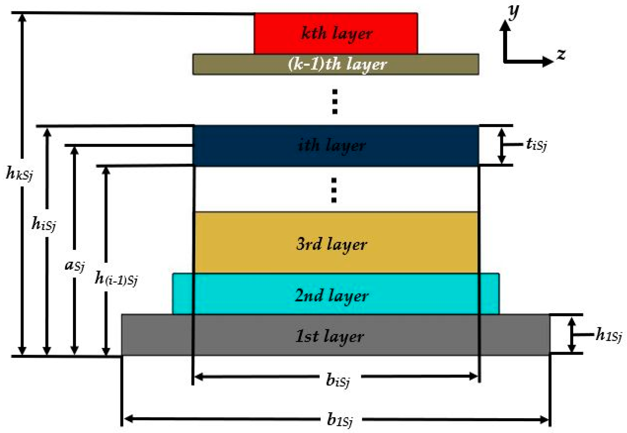
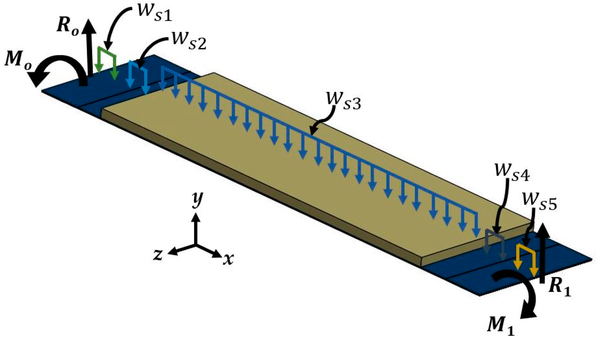
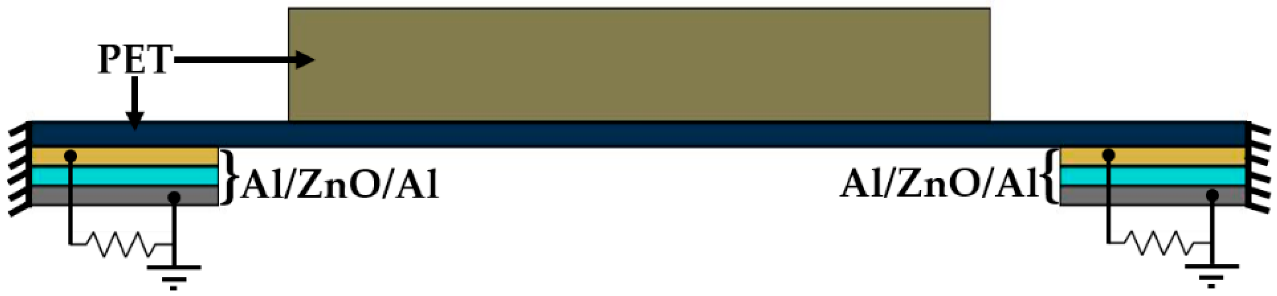
2.1. Design
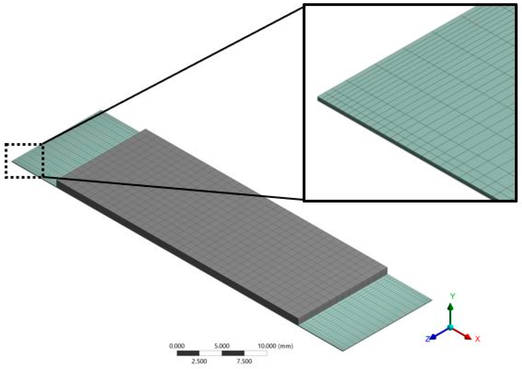
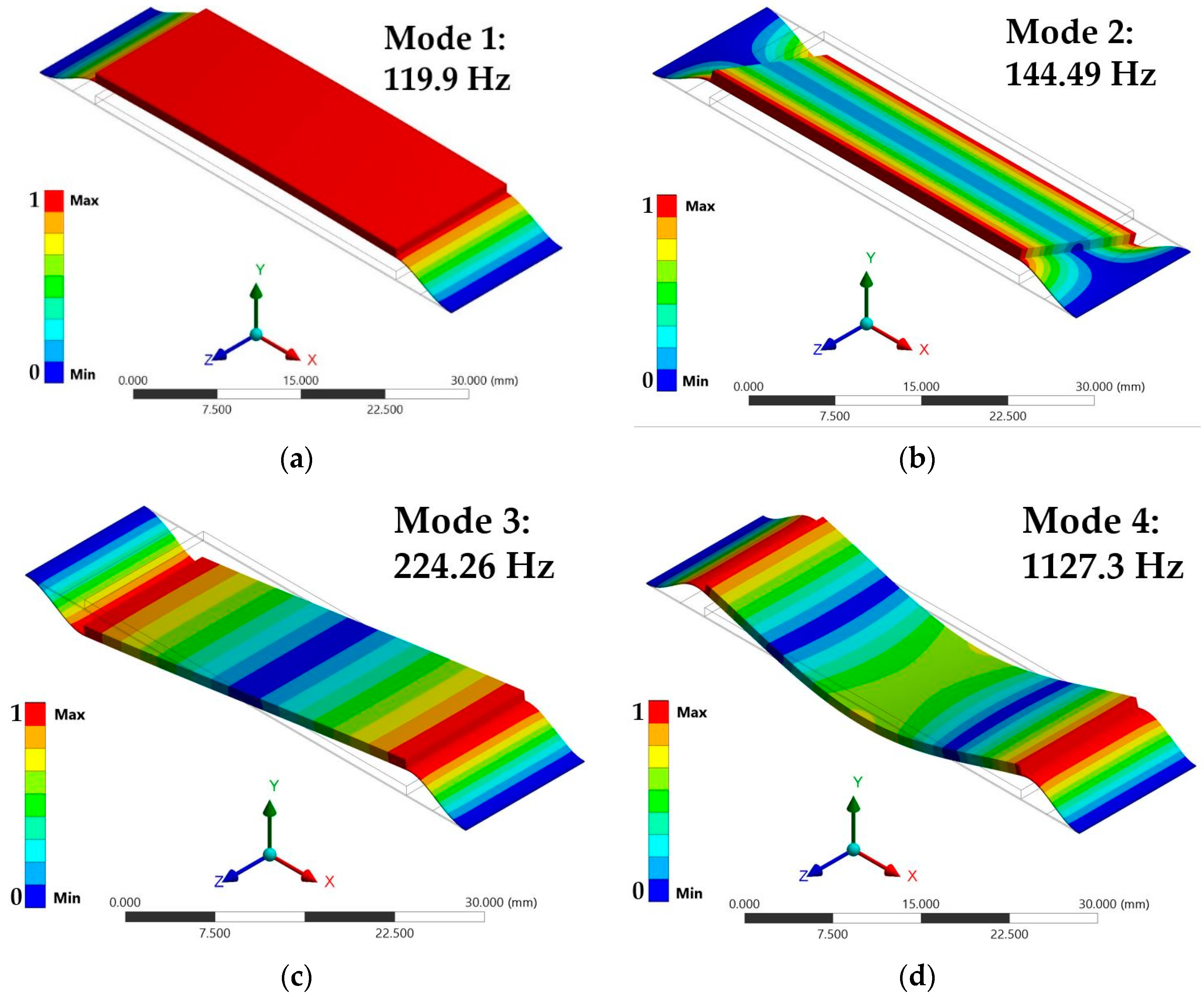
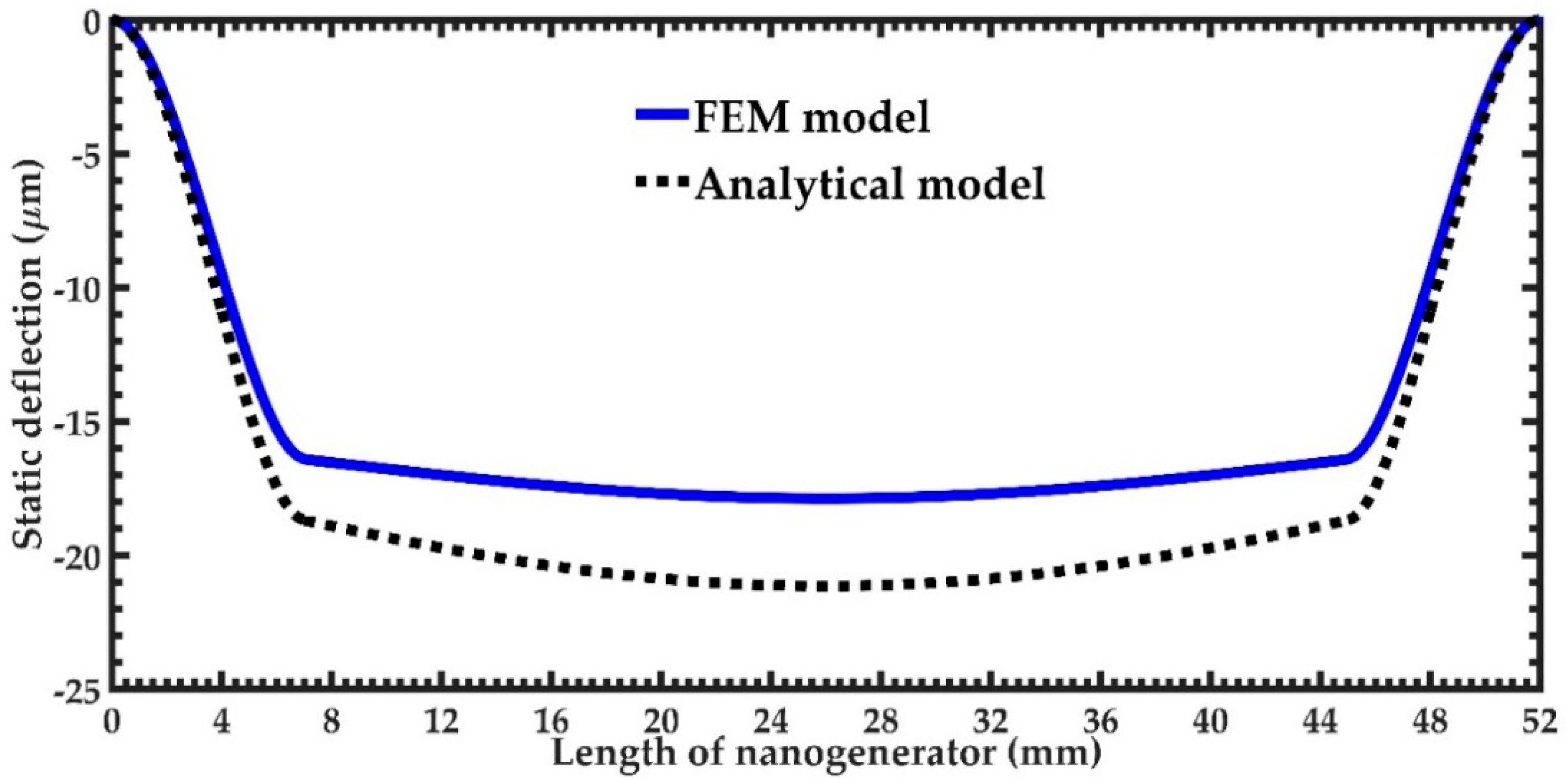
2.2. Finite Element Method (FEM) Models
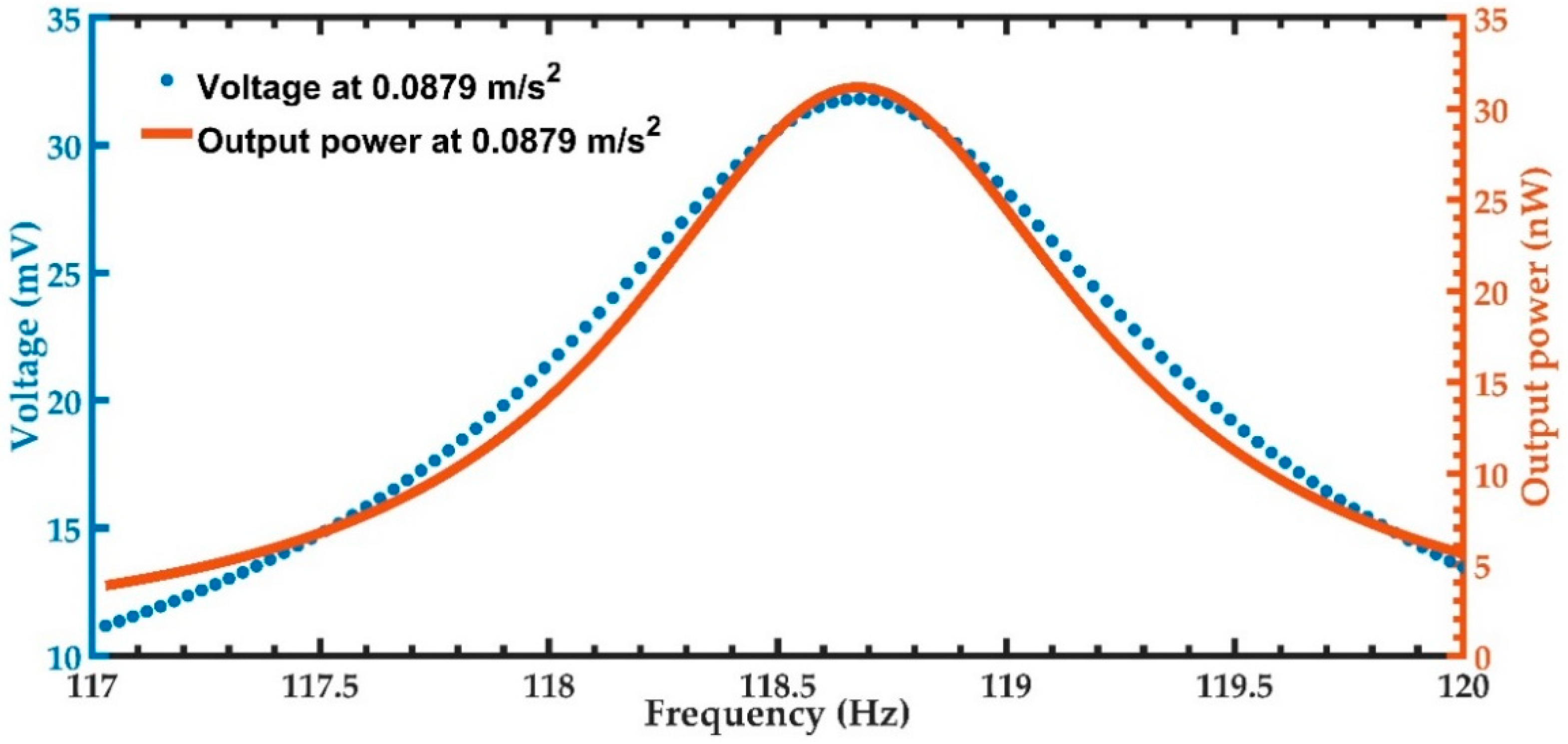
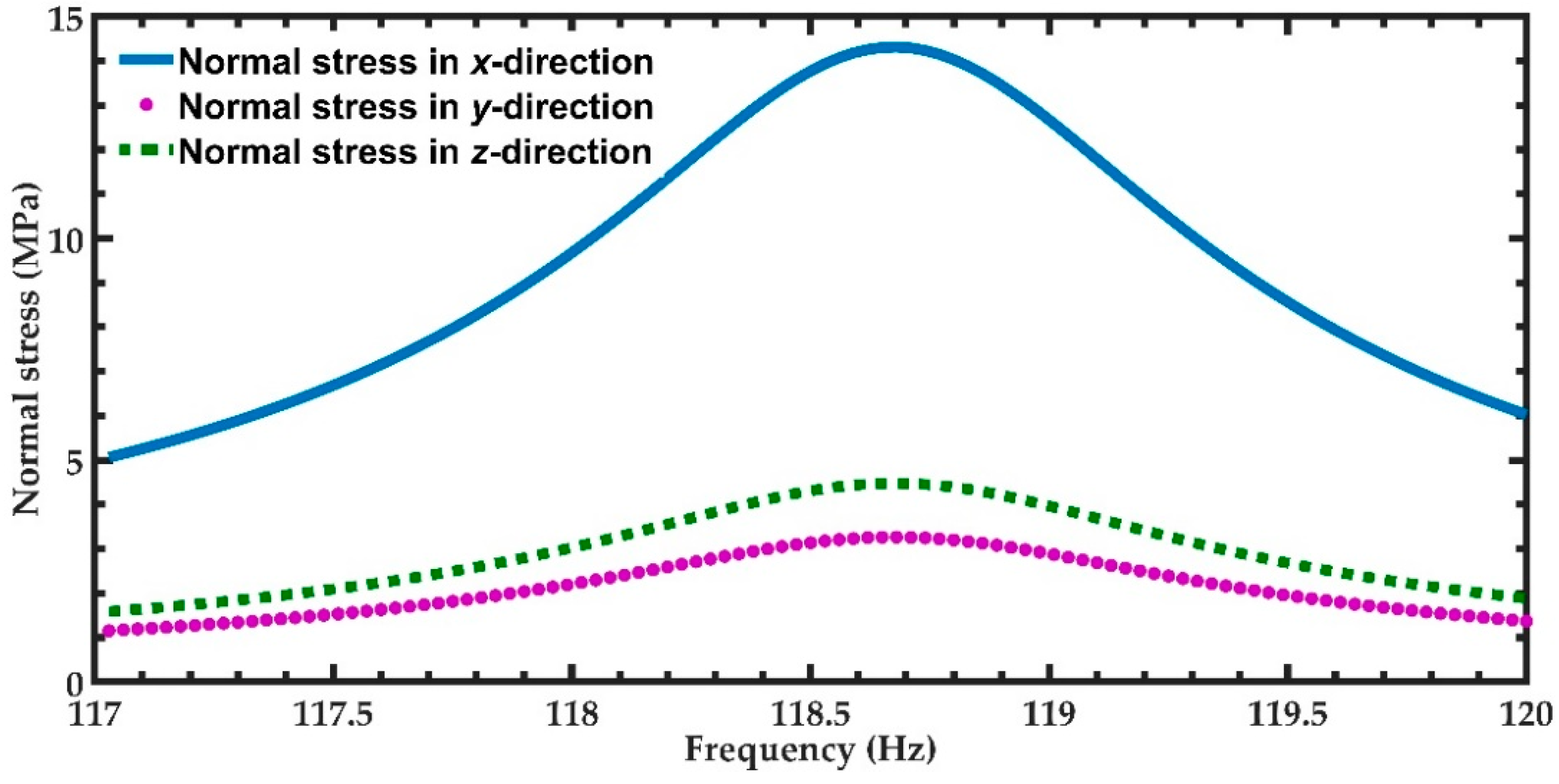
3. Results and Discussion
4. Conclusions
Author Contributions
Funding
Acknowledgments
Conflicts of Interest
Appendix A
References
- Mallick, D.; Constantinou, P.; Podder, P.; Roy, S. Multi-frequency MEMS electromagnetic energy harvesting. Sens. Actuators A Phys. 2017, 264, 247–259. [Google Scholar] [CrossRef]
- Li, X.; Upadrashta, D.; Yu, K.; Yang, Y. Analytical modeling and validation of multi-mode piezoelectric energy harvester. Mech. Syst. Signal Process. 2019, 124, 613–631. [Google Scholar] [CrossRef]
- Zhang, H.; Marty, F.; Xia, X.; Zi, Y.; Bourouina, T.; Galayko, D.; Basset, P. Employing a MEMS plasma switch for conditioning high-voltage kinetic energy harvesters. Nat. Commun. 2020, 11, 3221. [Google Scholar] [CrossRef]
- Debnath, B.; Kumar, R. A new Tapered-L shaped springs based MEMS piezoelectric vibration energy harvester designed for small rolling bearing fault detection. Microsyst. Technol. 2020, 26, 2407–2422. [Google Scholar] [CrossRef]
- Saxena, S.; Sharma, R.; Pant, B.D. Fabrication process for very-low frequency operation of guided two-beam piezoelectric energy harvester. Microsyst. Technol. 2020, 26, 2479–2486. [Google Scholar] [CrossRef]
- Liu, J.; Zuo, H.; Xia, W.; Luo, Y.; Yao, D.; Chen, Y.; Wang, K.; Li, Q. Wind energy harvesting using piezoelectric macro fiber composites based on flutter mode. Microelectron. Eng. 2020, 231, 111333. [Google Scholar] [CrossRef]
- Yuan, H.; Lei, T.; Qin, Y.; Yang, R. Flexible electronic skins based on piezoelectric nanogenerators and piezotronics. Nano Energy 2019, 59, 84–90. [Google Scholar] [CrossRef]
- Jenkins, K.; Kelly, S.; Nguyen, V.; Wu, Y.; Yang, R. Piezoelectric diphenylalanine peptide for greatly improved flexible nanogenerators. Nano Energy 2018, 51, 317–323. [Google Scholar] [CrossRef]
- Ding, X.; Cao, H.; Zhang, X.; Li, M.; Liu, Y. Large Scale Triboelectric Nanogenerator and Self-Powered Flexible Sensor for Human Sleep Monitoring. Sensors 2018, 18, 1713. [Google Scholar] [CrossRef] [Green Version]
- Ali, S.; Khan, S.; Bermak, A. All-Printed Human Activity Monitoring and Energy Harvesting Device for Internet of Thing Applications. Sensors 2019, 19, 1197. [Google Scholar] [CrossRef] [Green Version]
- Rao, J.; Chen, Z.; Zhao, D.; Yin, Y.; Wang, X.; Yi, F. Recent Progress in Self-Powered Skin Sensors. Sensors 2019, 19, 2763. [Google Scholar] [CrossRef] [Green Version]
- Nguyen, V.; Kelly, S.; Yang, R. Piezoelectric peptide-based nanogenerator enhanced by single-electrode triboelectric nanogenerator. APL Mater. 2017, 5, 074108. [Google Scholar] [CrossRef]
- Nguyen, V.; Zhu, R.; Yang, R. Environmental effects on nanogenerators. Nano Energy 2015, 14, 49–61. [Google Scholar] [CrossRef] [Green Version]
- Blokhina, E.; El Aroudi, A.; Alarcon, E.; Galayko, D. Nonlinearity in Energy Harvesting Systems; Blokhina, E., El Aroudi, A., Alarcon, E., Galayko, D., Eds.; Springer International Publishing: Cham, Switzerland, 2016; ISBN 978-3-319-20354-6. [Google Scholar]
- Nunes-Pereira, J.; Costa, P.; Lanceros-Mendez, S. Piezoelectric Energy Production; Elsevier Ltd.: Amsterdam, The Netherlands, 2018; Volume 3–5, ISBN 9780128095973. [Google Scholar]
- Beeby, S.P.; Torah, R.N.; Tudor, M.J.; Glynne-Jones, P.; O’Donnell, T.; Saha, C.R.; Roy, S. A micro electromagnetic generator for vibration energy harvesting. J. Micromech. Microeng. 2007, 17, 1257–1265. [Google Scholar] [CrossRef]
- Jia, Y.; Wei, X.; Xu, L.; Wang, C.; Lian, P.; Xue, S.; Al-Saadi, A.; Shi, Y. Multiphysics vibration FE model of piezoelectric macro fibre composite on carbon fibre composite structures. Compos. Part B Eng. 2019, 161, 376–385. [Google Scholar] [CrossRef] [Green Version]
- Zhang, G.; Gao, S.; Liu, H.; Zhang, W. Design and performance of hybrid piezoelectric-electromagnetic energy harvester with trapezoidal beam and magnet sleeve. J. Appl. Phys. 2019, 125. [Google Scholar] [CrossRef]
- Homayouni-Amlashi, A.; Mohand-Ousaid, A.; Rakotondrabe, M. Analytical Modelling and Optimization of a Piezoelectric Cantilever Energy Harvester with In-Span Attachment. Micromachines 2020, 11, 59. [Google Scholar] [CrossRef] [PubMed]
- Tao, K.; Xue, B.; Li, Q.; Hu, W.; Shimon, L.J.M.; Makam, P.; Si, M.; Yan, X.; Zhang, M.; Cao, Y.; et al. Stable and optoelectronic dipeptide assemblies for power harvesting. Mater. Today 2019, 30, 10–16. [Google Scholar] [CrossRef]
- Yin, X.; Liu, D.; Zhou, L.; Li, X.; Xu, G.; Liu, L.; Li, S.; Zhang, C.; Wang, J.; Wang, Z.L. A Motion Vector Sensor via Direct-Current Triboelectric Nanogenerator. Adv. Funct. Mater. 2020, 30, 2002547, in press. [Google Scholar] [CrossRef]
- Feng, Y.; Jiang, T.; Liang, X.; An, J.; Wang, Z.L. Cylindrical triboelectric nanogenerator based on swing structure for efficient harvesting of ultra-low-frequency water wave energy. Appl. Phys. Rev. 2020, 7, 021401. [Google Scholar] [CrossRef]
- Wu, Z.; Cheng, T.; Wang, Z.L. Self-Powered Sensors and Systems Based on Nanogenerators. Sensors 2020, 20, 2925. [Google Scholar] [CrossRef] [PubMed]
- Wu, C.; Huang, H.; Li, R.; Fan, C. Research on the Potential of Spherical Triboelectric Nanogenerator for Collecting Vibration Energy and Measuring Vibration. Sensors 2020, 20, 1063. [Google Scholar] [CrossRef] [PubMed] [Green Version]
- Chen, J.; Zhang, C.; Xuan, W.; Yu, L.; Dong, S.; Xie, Y.; Yin, W.; Luo, J. Triboelectric Nanogenerator-Based Self-Powered Resonant Sensor for Non-Destructive Defect Detection. Sensors 2019, 19, 3262. [Google Scholar] [CrossRef] [PubMed] [Green Version]
- Akhtar, F.; Rehmani, M.H. Energy replenishment using renewable andtraditional energy resources for sustainable wireless sensor networks: A review. Renew. Sustain. Energy Rev. 2015, 1, 769–784. [Google Scholar] [CrossRef]
- Aleksandrova, M.; Kolev, G.; Vucheva, Y.; Pathan, H.; Denishev, K. Characterization of piezoelectric microgenerator with nanobranched ZnO grown on a polymer coated flexible substrate. Appl. Sci. 2017, 7, 890. [Google Scholar] [CrossRef] [Green Version]
- Prušáková, L.; Novák, P.; Kulha, P.; Očenášek, J.; Savková, J.; Pastorek, L.; Šutta, P. Modeling and fabrication of single cantilever piezoelectric microgenerator with optimized Zno active layer. Thin Solid Films 2015, 591, 305–310. [Google Scholar] [CrossRef]
- Gu, L.; Liu, J.; Cui, N.; Xu, Q.; Du, T.; Zhang, L.; Wang, Z.; Long, C.; Qin, Y. Enhancing the current density of a piezoelectric nanogenerator using a three-dimensional intercalation electrode. Nat. Commun. 2020, 11, 1030. [Google Scholar] [CrossRef] [PubMed] [Green Version]
- Bairagi, S.; Ghosh, S.; Ali, S.W. A fully sustainable, self-poled, bio-waste based piezoelectric nanogenerator: Electricity generation from pomelo fruit membrane. Sci. Rep. 2020, 10, 12121. [Google Scholar] [CrossRef]
- Koç, M.; Paralı, L.; San, O. Fabrication and vibrational energy harvesting characterization of flexible piezoelectric nanogenerator (PEN) based on PVDF/PZT. Polym. Test. 2020, 90, 106695. [Google Scholar] [CrossRef]
- Lee, D.W.; Jeong, D.G.; Kim, J.H.; Kim, H.S.; Murillo, G.; Lee, G.H.; Song, H.C.; Jung, J.H. Polarization-controlled PVDF-based hybrid nanogenerator for an effective vibrational energy harvesting from human foot. Nano Energy 2020, 76, 105066. [Google Scholar] [CrossRef]
- Yang, P.K.; Chou, S.A.; Hsu, C.H.; Mathew, R.J.; Chiang, K.H.; Yang, J.Y.; Chen, Y.T. Tin disulfide piezoelectric nanogenerators for biomechanical energy harvesting and intelligent human-robot interface applications. Nano Energy 2020, 75, 104879. [Google Scholar] [CrossRef]
- Manjula, Y.; Kumar, R.R.; Raju, P.M.S.; Kumar, G.A.; Rao, T.V.; Akshaykranth, A.; Supraja, P. Piezoelectric flexible nanogenerator based on ZnO nanosheet networks for mechanical energy harvesting. Chem. Phys. 2020, 533, 110699. [Google Scholar] [CrossRef]
- Qian, F.; Zhou, S.; Zuo, L. Improving the off-resonance energy harvesting performance using dynamic magnetic preloading. Acta Mech. Sin. 2020, 36, 624–634. [Google Scholar] [CrossRef]
- Roundy, S.; Wright, P.K. A piezoelectric vibration based generator for wireless electronics. Smart Mater. Struct. 2004, 13, 1131. [Google Scholar] [CrossRef] [Green Version]
- Martínez-Cisneros, E.; Velosa-Moncada, L.A.; Del Angel-Arroyo, J.A.; Aguilera-Cortés, L.A.; Cerón-Álvarez, C.A.; Herrera-May, A.L. Electromechanical Modeling of MEMS-Based Piezoelectric Energy Harvesting Devices for Applications in Domestic Washing Machines. Energies 2020, 13, 617. [Google Scholar] [CrossRef] [Green Version]
- Elvira-Hernández, E.A.; Uscanga-González, L.A.; de León, A.; López-Huerta, F.; Herrera-May, A.L. Electromechanical Modeling of a Piezoelectric Vibration Energy Harvesting Microdevice Based on Multilayer Resonator for Air Conditioning Vents at Office Buildings. Micromachines 2019, 10, 211. [Google Scholar] [CrossRef] [Green Version]
- Qin, Y.; Wei, T.; Zhao, Y.; Chen, H. Simulation and experiment on bridge-shaped nonlinear piezoelectric vibration energy harvester. Smart Mater. Struct. 2019, 28, 045015. [Google Scholar] [CrossRef]
- Abdelkefi, A.; Barsallo, N. Nonlinear analysis and power improvement of broadband low-frequency piezomagnetoelastic energy harvesters. Nonlinear Dyn. 2016, 83, 41–56. [Google Scholar] [CrossRef]
- Dutoit, N.E.; Wardle, B.L.; Kim, S.-G. Design Considerations for MEMS-Scale Piezoelectric Mechanical Vibration Energy Harvesters. Integr. Ferroelectr. 2005, 71, 121–160. [Google Scholar] [CrossRef]
- Damya, A.; Abbaspour Sani, E.; Rezazadeh, G. An innovative piezoelectric energy harvester using clamped–clamped beam with proof mass for WSN applications. Microsyst. Technol. 2020, 26, 3203–3211. [Google Scholar] [CrossRef]
- Wang, Z.; Matova, S.; Elfrink, R.; Jambunathan, M.; de Nooijer, C.; van Schaijk, R.; Vullers, R.J.M. A piezoelectric vibration harvester based on clamped-guided beams. In Proceedings of the 2012 IEEE 25th International Conference on Micro Electro Mechanical Systems (MEMS), Paris, France, 29 January–2 February 2012; pp. 1201–1204. [Google Scholar] [CrossRef]
- Pan, C.T.; Liu, Z.H.; Chen, Y.C. Study of broad bandwidth vibrational energy harvesting system with optimum thickness of PET substrate. Curr. Appl. Phys. 2012, 12, 684–696. [Google Scholar] [CrossRef]
- Panda, P.K. Review: Environmental friendly lead-free piezoelectric materials. J. Mater. Sci. 2009, 44, 5049–5062. [Google Scholar] [CrossRef] [Green Version]
- Lee, L.T.; Mohamed, M.A.; Yahya, I.; Kulothungan, J.; Muruganathan, M.; Mizuta, H. Comparison of piezoelectric energy harvesting performance using silicon and graphene cantilever beam. Microsyst. Technol. 2018, 24, 3783–3789. [Google Scholar] [CrossRef]
- Rao, S.S. Vibration of Continuous Systems, 2nd ed.; Wiley: Hoboken, NJ, USA, 2020. [Google Scholar]
- Herrera-May, A.L.; García-Ramírez, P.J.; Aguilera-Cortés, L.A.; Plascencia-Mora, H.; García-González, L.; Manjarrez, E.; Narducci, M.; Figueras, E. Analytical modeling for the bending resonant frequency of sensors based on micro and nanoresonators with complex structural geometry. IEEE Sens. J. 2011, 11, 1361–1374. [Google Scholar] [CrossRef]
- Vasiliev, V.; Morozov, E. Mechanics and Analysis of Composite Materials, 1st ed.; Elsevier: Amsterdam, The Netherlands, 2001. [Google Scholar]
- Weaver, W., Jr.; Timoshenko, S.P.; Young, D.H. Vibration Problems in Engineering, 5th ed.; John Wiley & Sons: New York, NY, USA, 1990. [Google Scholar]
- Bauchau, O.A.; Craig, J.I. Euler-Bernoulli beam theory. In Structural Analysis. Solid Mechanics and Its Applications; Bauchau, O.A., Craig, J.I., Eds.; Springer: Dordrecht, The Netherlands, 2009; Volume 163. [Google Scholar] [CrossRef]
- Craig, R.R., Jr. Mechanics of Materials, 1st ed.; Wiley: New York, NY, USA, 1996. [Google Scholar]
- Cimalla, V.; Foerster, C.; Will, F.; Tonisch, K.; Brueckner, K.; Stephan, R.; Mein, M.E.; Ambacher, O.; Aperathitis, E. Pulsed mode operation of strained microelectromechanical resonators in air. Appl. Phys. Lett. 2006, 88, 253501. [Google Scholar] [CrossRef]
- Vignola, J.F.; Judge, J.A.; Jarzynski, J.; Zalalutdinov, M.; Houston, B.H.; Baldwin, J.W. Effect of viscous loss on mechanical resonators designed for mass detection. Appl. Phys. Lett. 2006, 88, 041921. [Google Scholar] [CrossRef]
- Blom, F.R.; Bouwstra, S.; Elwenspoek, M.; Fluitman, J.H.J. Dependence of the quality factor of micromachined silicon beam resonators on pressure and geometry. J. Vac. Sci. Technol. B Microelectron. Nanom. Struct. 1992, 10, 19. [Google Scholar] [CrossRef] [Green Version]
- Kuang, Y.; Daniels, A.; Zhu, M. A sandwiched piezoelectric transducer with flex end-caps for energy harvesting in large force environments. J. Phys. D Appl. Phys. 2017, 50, 345501. [Google Scholar] [CrossRef]
- Ong, C.W.; Zong, D.G.; Aravind, M.; Choy, C.L.; Lu, D.R. Tensile strength of zinc oxide films measured by a microbridge method. J. Mater. Res. 2003, 18, 2464–2472. [Google Scholar] [CrossRef] [Green Version]
- Champagne, M.F.; Huneault, M.A.; Roux, C.; Peyrel, W. Reactive compatibilization of polypropylene/polyethylene terephthalate blends. Polym. Eng. Sci. 1999, 39, 976–984. [Google Scholar] [CrossRef]


| Geometric Parameter | Magnitude |
|---|---|
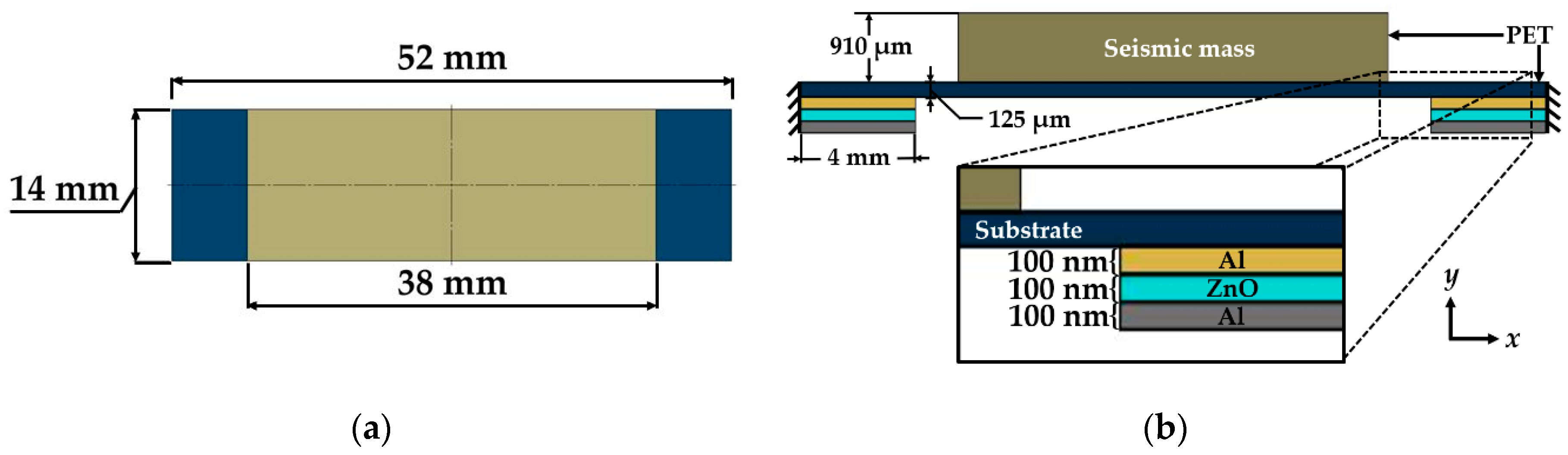
| L1 = L5 | 4 mm |
| L2= L4 | 3 mm |
| L3 | 38 mm |
| t1S1 = t2S1 = t3S1 = t1S5 = t2S5 = t3S5 | 100 nm |
| t4S1 = t4S2 = t4S3 = t4S4 = t4S5 | 125 μm |
| t5S3 | 910 μm |
| h1S1 = h1S5 | 100 nm |
| h2S1 = h2S5 | 200 nm |
| h3S1 = h3S5 | 300 nm |
| h4S1 = h4S2 = h4S3 = h4S4 = h4S5 | 125.3 μm |
| h5S3 | 1035.3 μm |
| Parameter | Magnitude |
|---|---|
| M0 = M1 | 14.5893 × 10⁻⁶ Nm |
| R0 = R1 | 3.9499 × 10⁻³ N |
| ωS1 = ωS5 | 24.1883 × 10⁻³ N/m |
| ωS2 = ωS4 | 24.0345 × 10⁻³ N/m |
| ωS3 | 199.0056 N/m |
| (EIz)S1 = (EIz)S5 | 6.8714 × 10⁻⁶ Nm2 |
| (EIz)S2 = (EIz)S4 | 5.4687 × 10⁻⁶ Nm2 |
| (EIz)S3 | 3.1044 × 10⁻³ Nm2 |
| Material Property | PET | Aluminum | ZnO |
|---|---|---|---|
| Young modulus E (GPa) | 2.4 | 71 | 137 |
| Density ρ (k/m3) | 1400 | 2770 | 5665 |
| Poisson ratio υ | 0.36 | 0.33 | 0.34 |
| ZnO piezoelectric stress matrix (e) |
| ZnO piezoelectric dielectric matrix (εr) under the constant strain. |
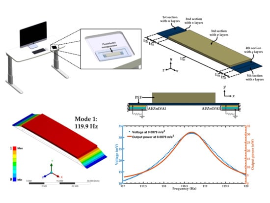
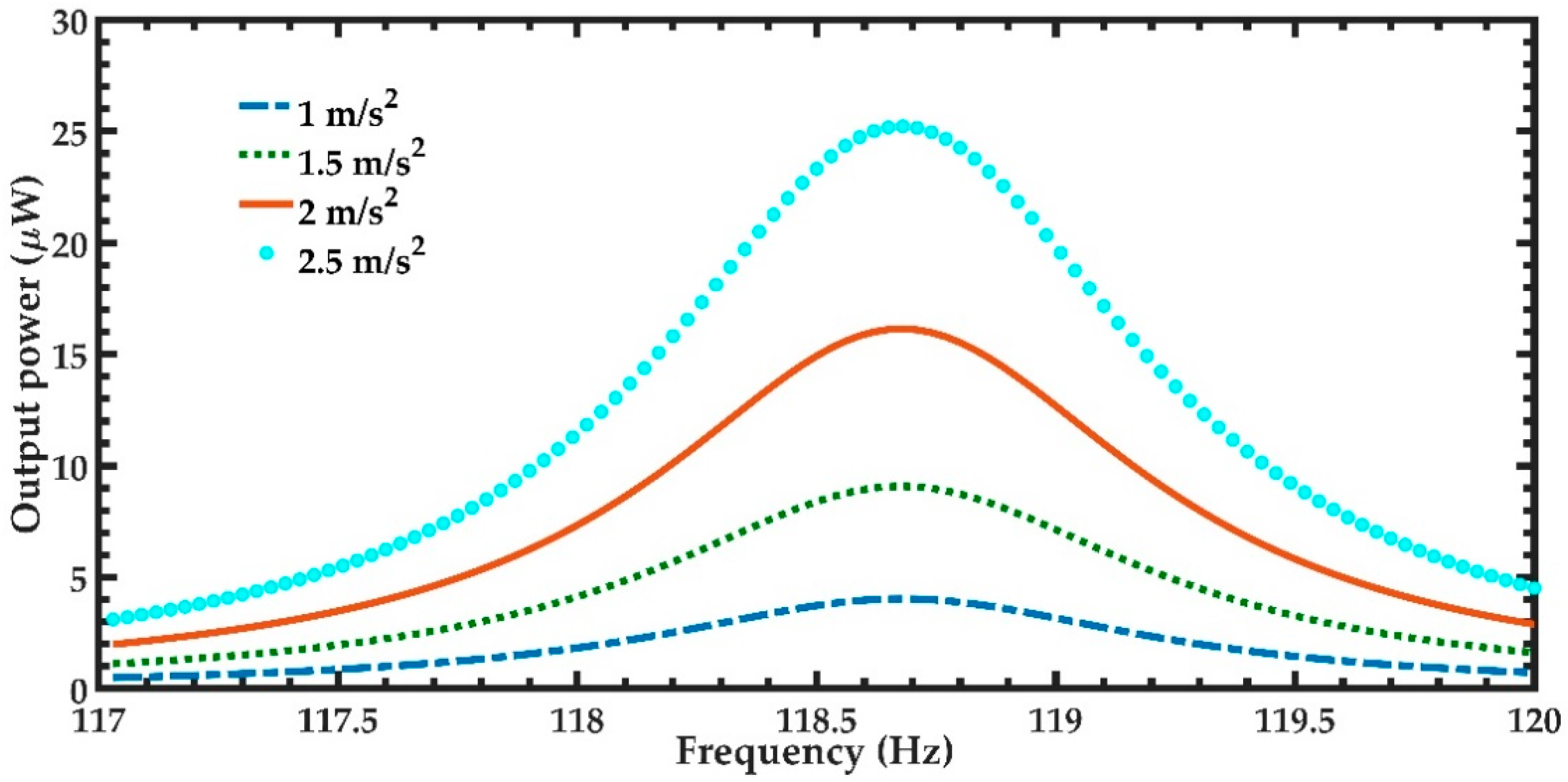
| Acceleration (m/s2) | Total Output Power (µW) | Total Output Power Density (W/m3) |
|---|---|---|
| 8.79 × 10⁻² | 62.36 × 10⁻³ | 101.82 × 10⁻³ |
| 1.0 | 8.06 | 13.16 |
| 1.5 | 18.14 | 29.62 |
| 2.0 | 32.28 | 52.71 |
| 2.5 | 50.44 | 82.36 |
© 2020 by the authors. Licensee MDPI, Basel, Switzerland. This article is an open access article distributed under the terms and conditions of the Creative Commons Attribution (CC BY) license (http://creativecommons.org/licenses/by/4.0/).
Share and Cite
Elvira-Hernández, E.A.; Anaya-Zavaleta, J.C.; Martínez-Cisneros, E.; López-Huerta, F.; Aguilera-Cortés, L.A.; Herrera-May, A.L. Electromechanical Modeling of Vibration-Based Piezoelectric Nanogenerator with Multilayered Cross-Section for Low-Power Consumption Devices. Micromachines 2020, 11, 860. https://0-doi-org.brum.beds.ac.uk/10.3390/mi11090860
Elvira-Hernández EA, Anaya-Zavaleta JC, Martínez-Cisneros E, López-Huerta F, Aguilera-Cortés LA, Herrera-May AL. Electromechanical Modeling of Vibration-Based Piezoelectric Nanogenerator with Multilayered Cross-Section for Low-Power Consumption Devices. Micromachines. 2020; 11(9):860. https://0-doi-org.brum.beds.ac.uk/10.3390/mi11090860
Chicago/Turabian StyleElvira-Hernández, Ernesto A., Juan C. Anaya-Zavaleta, Eustaquio Martínez-Cisneros, Francisco López-Huerta, Luz Antonio Aguilera-Cortés, and Agustín L. Herrera-May. 2020. "Electromechanical Modeling of Vibration-Based Piezoelectric Nanogenerator with Multilayered Cross-Section for Low-Power Consumption Devices" Micromachines 11, no. 9: 860. https://0-doi-org.brum.beds.ac.uk/10.3390/mi11090860