
Analytical Modeling and Validation of a Preloaded Piezoceramic Current Output


1
School of Mechanical, Electrical and Information Engineering, Shandong University, Weihai 204209, China
2
Department of Engineering Mechanics, Zhejiang University, Hangzhou 310027, China
*
Author to whom correspondence should be addressed.
Micromachines 2021, 12(4), 353; https://0-doi-org.brum.beds.ac.uk/10.3390/mi12040353
Submission received: 27 February 2021
/
Revised: 22 March 2021
/
Accepted: 22 March 2021
/
Published: 25 March 2021
(This article belongs to the Special Issue Piezoelectric Nanogenerators for Micro-Energy and Self-Powered Sensors)
Abstract
:Energy harvesting using piezoceramic has drawn a lot of attention in recent years. Its potential usage in microelectromechanical systems is starting to become a reality thanks to the development of an integrated circuit. An accurate equivalent circuit of piezoceramic is important in energy harvesting and the sensing system. A piezoceramic is always considered to be a current source according to empirical testing, instead of the derivation from its piezoelectric characteristics, which lacks accuracy under complicated mechanical excitation situations. In this study, a new current output model is developed to accurately estimate its value under various kinds of stimulation. Considering the frequency, amplitude and preload variation imposed on a piezoceramic, the multivariate model parameters are obtained in relation to piezo coefficients. Using this model, the current output could be easily calculated without experimental testing in order to quickly estimate the output power in energy harvesting whatever its geometric shape and the various excitations.
1. Introduction
Wireless sensor networks (WSNs) are widely used in the industry, for military applications and smart homes, to monitor the operating conditions or environmental status. Though the data can be transmitted wirelessly, the batteries need to be recharged or replaced periodically. The strong demand for self-powered wireless sensor network nodes encourages researchers to study different energy harvesting mechanisms: solar, piezoelectricity, thermoelectricity, electromagnetism and so on. A piezoceramic can be used to transfer the ubiquitous vibration into electricity so as to prolong the battery lifespan or even provide life-long power for sensor nodes.
By designing a self-powered electronic gadget, lots of factors, such as the environmental parameters (energy type, intensity, characteristics, etc.), energy consumption, energy conversion mechanism, transfer efficiency, etc., should be carefully studied or coupled. Solar energy is abundant and of high efficiency, especially in an outdoor situation, but it is susceptible to the weather. Otherwise, vibration is a promising energy source for embedded self-powered devices [1]. The wireless sensor nodes’ power consumption varies from nanowatts to watts, since energy dissipation is a key issue for all kinds of WSNs. Considering the available environmental vibration energy density and achievable energy conversion efficiency are attained, a piezoelectric energy harvesting system can be used in cases lower than milliwatt or microwatt depending on its periodic or event-responded monitoring in an optimized WSN. Kim et al. [2] have reviewed the WSN energy consumption balancing (ECB) and categorized the powered consumption influencing factor including the node distribution, base station option and application type. Improvement measures can be introduced into the WSNs to maximize the use of energy to prolong node lifespan [2,3].
As a promising mechanism for self-powered sensor nodes, piezoelectric energy harvesting (PEH) has been studied by a number of researchers for the last two decades. Umeda [4], Shu [5], Yang [6] and others have studied the efficiency of mechanical energy transformation to electrical energy, which is an important indicator to optimize the coupling factors and PEH structure design. The lumped parameter model along with the Euler–Bernoulli beam theory is always used to model the PEH system, including the one degree of freedom (1DOF) [7] or 2DOF [8] vibration system. As the piezoceramic is considered a current source, the electric displacement is simplified to a linear relationship with external stress. Under an actual scene, the piezoceramic output changes along with the preload, frequency, etc. The output power is limited by the high impedance in a piezoceramic. A high-precision oscillation circuit can be used to enhance the output performance of the piezoceramic. Lots of efforts have been put on the interface circuit, which is a most important technique and can significantly improve the electricity energy extracted from the piezoceramic when accurately coupled. Lallart et al. [9,10,11,12,13,14] have studied the nonlinear interface circuit, as well as low-voltage, energy storage, wide bandwidth and self-powered situations.
Note that a piezoceramic is usually considered to be a current source paralleled with a capacitor, and its current output is essential to design a piezoelectric energy source when a micro-electro-mechanical systems (MEMS) device is fabricated in small size. The optimal design of the piezo source is fundamental in the self-powered WSN node, for example, the selection of piezoceramic type, geometric size, stimulation stress and so on. In different piezoelectric energy harvester structures, such as a bistable generator [15], tri-stable energy harvester [16], spring pendulum oscillator [17], clamped piezo-stack [18], etc., and a horizontal cantilever beam with the consideration of gravity, the piezoceramic is in a preloaded status which will affect its current output. It is necessary to establish a model that includes the common variables during the deployment of piezoceramic devices.
Liao [19] developed a reduced model to predict and optimize a cantilever beam energy harvesting system and it is efficiency to get an optimal resistance in beam-like structures. The current output, accompanied by its geometric size, stimulation characteristic and piezo coefficients is studied in this paper to further simplify the rapid prototyping energy source design. Regardless of whether the base structure is a cantilever beam, cymbal type or others, this model, derived from the stress distribution in a piezoceramic, gives an accurate estimation of the current output. Since an efficient energy harvesting system is the optimum design of different components, the selection of interface circuit elements is particularly important. Morel et al. studied the influence of the resistive, capacitive and inductive behavior in a piezoelectric energy harvesting system and derived a simplified model [20], and they also manufactured an extra low energy consumption integrated interface to achieve >91% efficiency of energy harvesting under shocks and 94% under periodic excitations [21]. Their studies have the potential to improve the interface-circuit parameter coupling for the current output model. The summary from Brenes et al. [22] facilitates the interface circuit implementation and helps to achieve the maximum power output in the piezoelectric energy harvesting. In the former studies, Ducharne and other researchers [23,24,25,26] have studied the nonlinearity in piezoceramic and its application in energy harvesting. The proposed model will include the nonlinearities as well.
In the next section, the current output model is established. Section 3 is the experimental validation of the model under different preloads, frequencies and excitation amplitudes. Conclusions will be drawn in the final section.
2. Model and Theory
2.1. Electromechanical Coupling Model
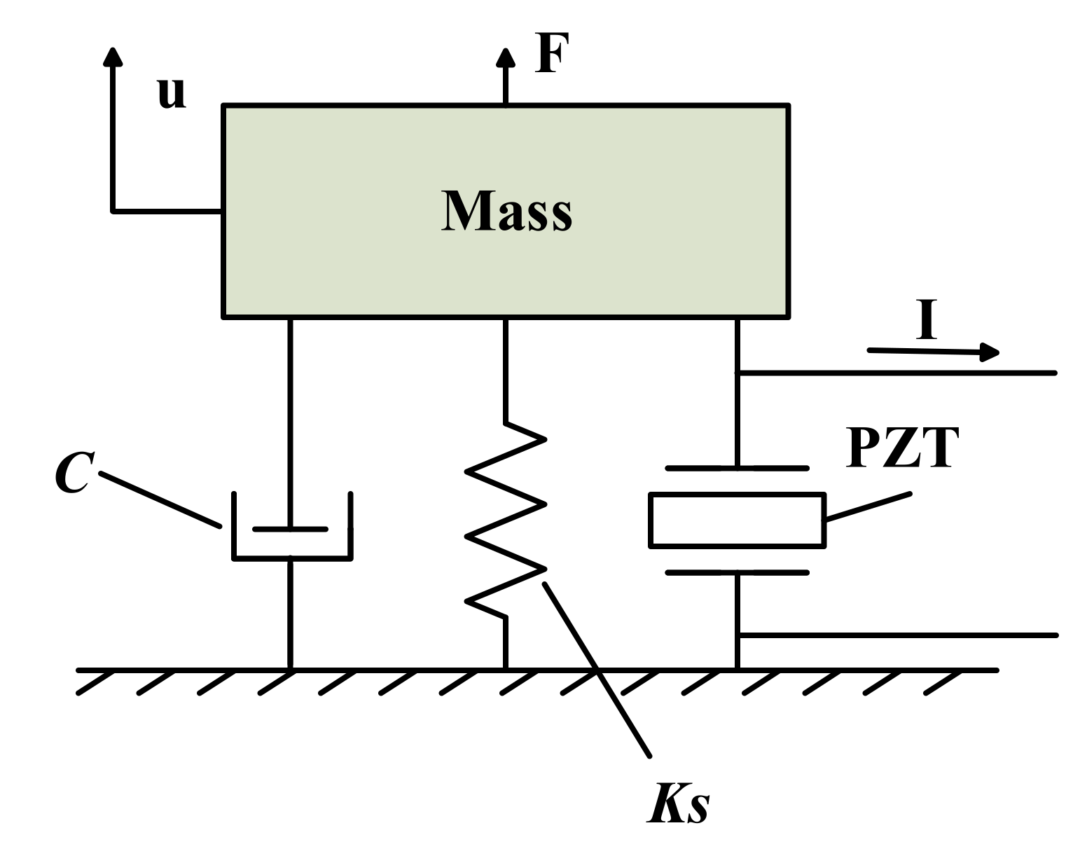
The electromechanical coupling model is established to combine electrical quantity with mechanical quantity [27]. In order to facilitate the analysis, this paper uses a single-degree-of-freedom case for the mathematical model [28]. The electromechanical coupling model of the vibration energy harvesting system can be represented by the “mass + damping + spring”, as shown in Figure 1.
The mechanical loss is equivalent to the viscous damper C, while M is the equivalent mass of the block, KS is the equivalent stiffness of the structure, F is the external excitation and u is the displacement of the structure. The governing equations of motion (1) can be obtained from Newton’s law [20,22,29].
Among them, ΣFi is the external force acting on the structure, including the external excitation F and the reaction force FP of piezoelectric plates.
For the piezoelectric system in this paper, the boundary conditions are short circuit and mechanically free. The piezoelectric equations are shown in Equation (2) [30], where T is the stress of the piezoelectric plate, S is the strain of the piezoelectric plate, E3 is the electric field strength, D is the electric displacement, sE33 is the short-circuit elastic compliance, d33 is the piezoelectric constant and εT33 is the constant stress dielectric permittivity.
V and I represent the voltage of the piezoelectric patch and the current flow, respectively. L and A represent the thickness and surface area of the piezoelectric patch, respectively. FP is the reaction force of the piezoelectric patch to the base structure. Equation (3), combined with Equation (2), can derive Equation (4) [20,22,30,31,32].
KPE is equivalent to the short-circuit stiffness of the piezoelectric block, CP is the equivalent capacitance of the piezoelectric block and α is the stress factor [31,32].
A global stiffness for both the mechanical structure and the piezoelectric disk can be defined as (5) when a piezoceramic is on short circuit (KPE) and on an open circuit (KPD). The global electromechanical coupling factor kt is then expressed in Equation (6). As the solution of this study is to estimate the short-circuit current, KPE is taken into account here.
According to the law of conservation of energy, the input energy of the whole system is assumed as E. In this system, the input energy is transformed into kinetic energy, elastic potential energy, loss and piezoelectric energy, respectively. Its expression is shown in Equation (7):
ED is mainly composed of heat loss QC and dielectric loss QD. As the vibration generates small polarization, and the loss angle tanδ is relatively small at low voltage, QD can be neglected. Its QC is mainly caused by ESR (Equivalent series resistance). The expression is as follows:
IRMS is the effective value of current output, XC is capacitive reactance, and Q is the quality factor of capacitance.
Multiply u on both sides of the Equation (1) and integrate t. From Hamilton’s Principle, the Equation (9) can be obtained [21].
Equation (9) can represent the existence of energy in the whole system, and the physical meanings represented by each of them are shown in Table 1 [21].
As can be seen from the table, is the energy we need. By multiplying the second sub-formula of Equation (4) by V and integrating t, the Equation (10) can be obtained.
is the energy stored in the equivalent capacitance. is the real energy flowing into the subsequent acquisition circuit and used for the load.
2.2. Current Output Model
Considering the dynamic characteristics of the piezoelectric ceramic and the external excitation force, Equation (1) can be expressed as follows:
What mainly matters in forced vibration is the steady-state vibration, whose solution is:
The natural frequency of cylindrical piezoceramic (PZT5, Φ6 × 5 mm) is extremely high compared with the exciting frequency, and the capacitor of the piezoceramic is 0.25 nF. The steady state solution can be simplified as follows:
Therefore, the voltage at both ends of the PZT V(t) is:
Its current output I(t) can be obtained as follows:
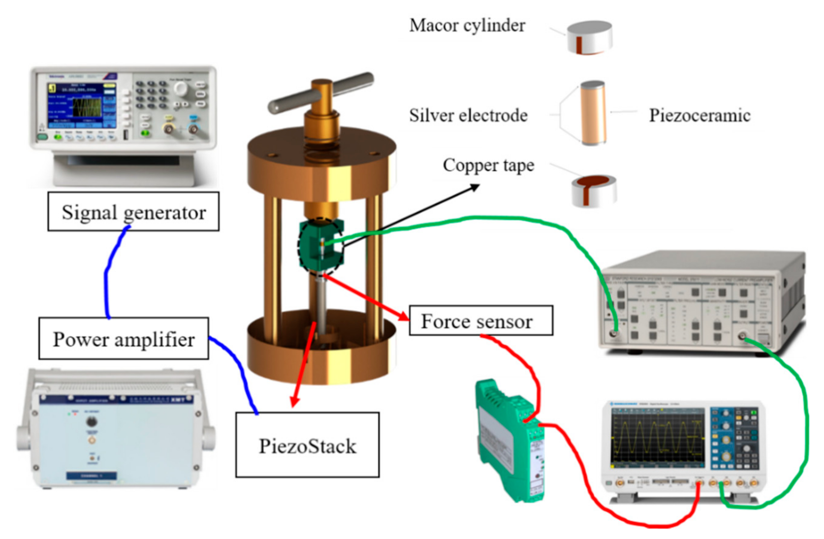
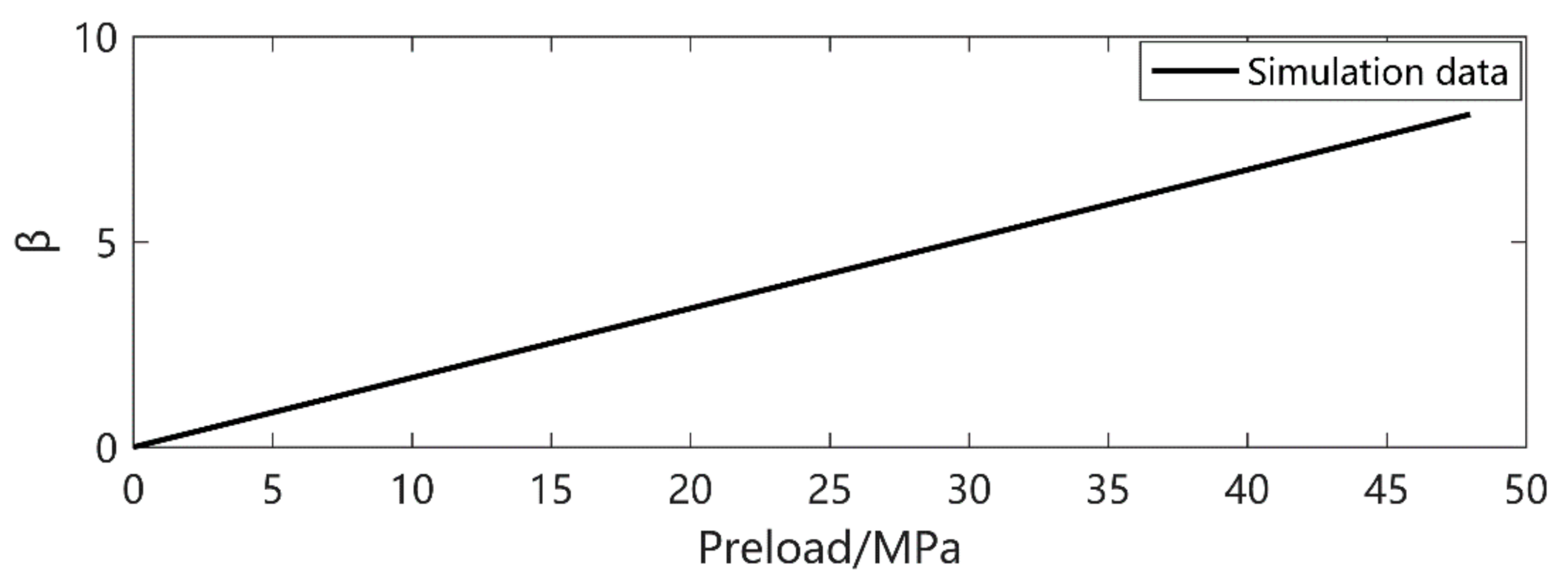
In order to consider the effect of preloading Ppre on the current output, the bias stress parameter β is introduced considering the mechanical conduct and dynamic factor, mainly affected by the contact type. As shown in Figure 2, the piezoceramic is compression-fixed block by block, in different material. PPre is necessary to keep these blocks together. The excitation amplitude is required to be smaller than the magnitude of PPre to assure the piezoceramic is in good mechanical contact. The equivalent stress applied to the piezoceramic should consider both the variation and the preload. Here, in this case, the β should always be positive. However, in a cantilever-beam-like structure, it can be either positive or negative, as a piezoceramic can be compressed or stretched. The stress T is expressed as T’:
In this experiment setup, the β value is expressed as:
Therefore, the final short circuit current of the system is:
Since the stress distribution is easily analyzed by the finite element method, a piezoceramic dedicated to be used in an energy harvesting system is designed accordingly. By the use of Equation (18), one can easily calculate the current output of the piezoceramic so as to select an appropriate energy extraction circuit and evaluate the satisfaction of energy supply [19,20].
3. Experimental Verification of Current Output Model
In order to verify the accuracy of the current output model, a preload test platform is built to measure the experimental data. Figure 2 shows the schematic diagram of the experimental connections. The platform consists of a signal generator (TEKTRONIX, AFG1062) which controls the power amplifier (COREMORROW), the oscilloscope (ROHDE&SCHWARZ, RTB2004), the force sensor and the current amplifier, connected as follows:
Figure 2.
Configuration of the experimental platform.

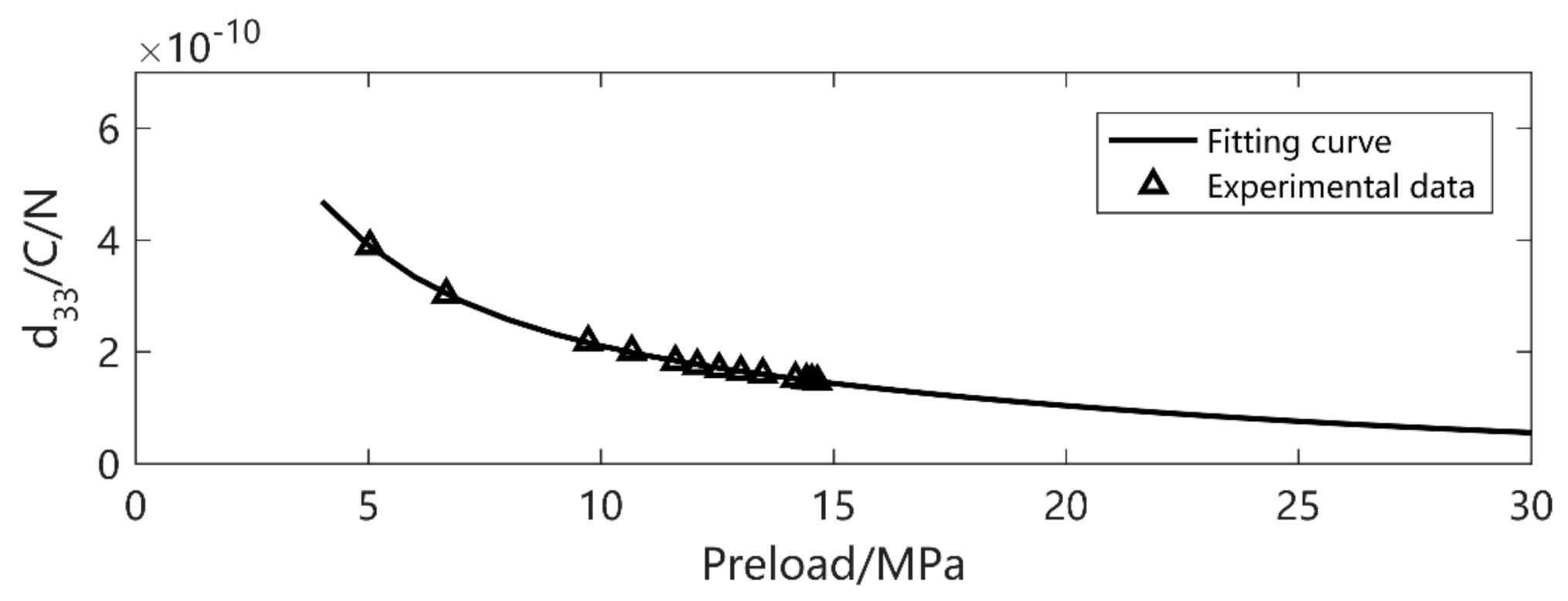
Then, the piezoceramic is excited under different amplitudes (5–70 MPa), preload pressure (5–45 MPa) and frequencies (5–70 Hz). Though the piezoelectric constitutive equations are always correct in any case, the piezo coefficients vary according to the external excitation. Under small excitation, d33 variation is mainly due to the preload. With the increase of preload, d33 decreases sharply at the beginning and then trends to be steady. Under the 5 MPa excitation, the preload varies. The experimental data and fitting figure are shown in Figure 3.
The curve of the adjustment parameter β is shown in Figure 4.
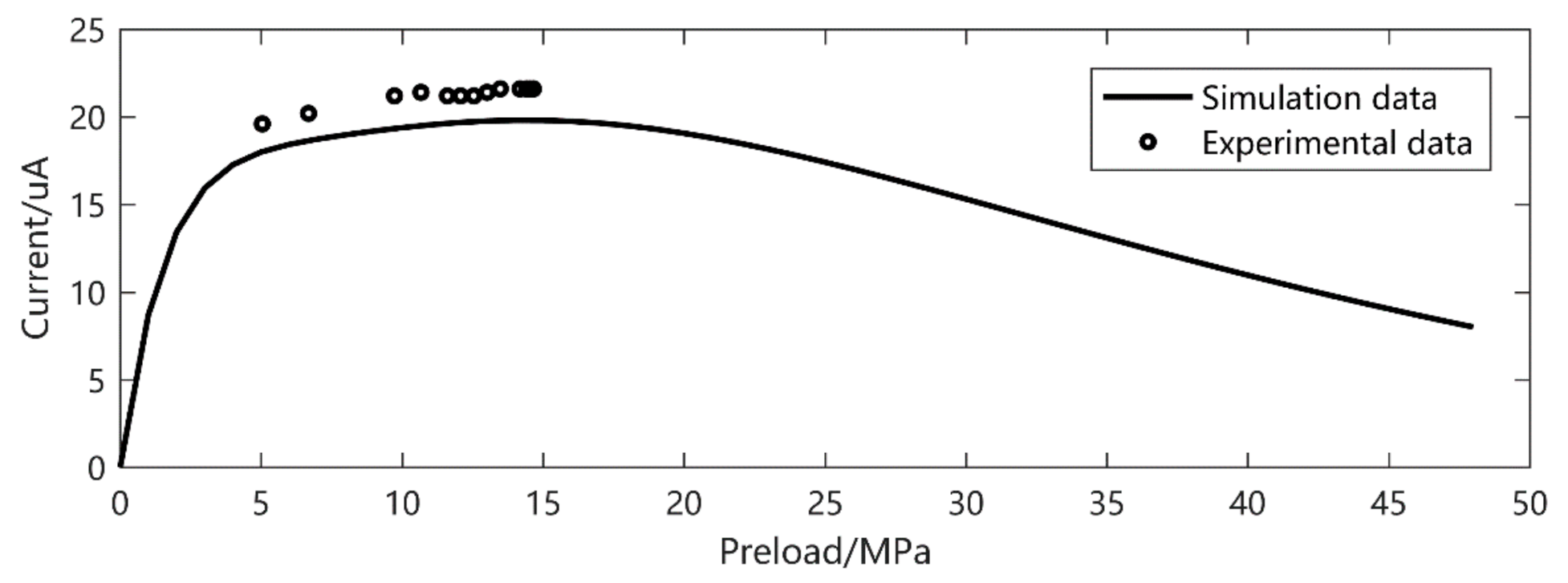
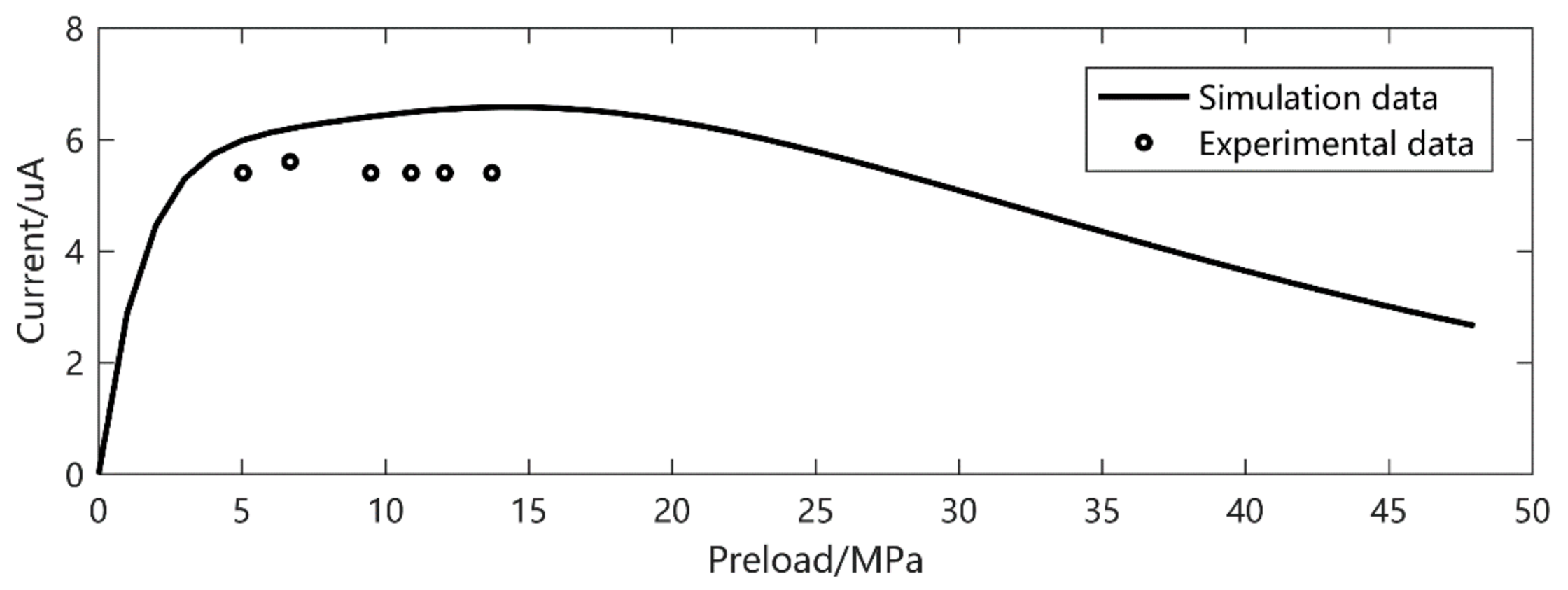
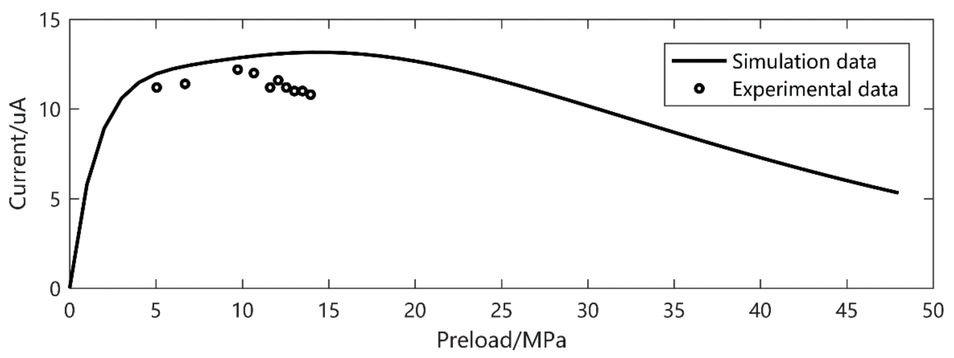
To verify the accuracy of the model under different excitation levels, the current output results under different frequencies, preload and excitation amplitudes were experimentally verified. When the excitation frequency is 30 Hz and the excitation amplitude is 11.76 MPa, the current output is shown in Figure 5. In another series of experiments, when the excitation amplitude is 5.86 MPa and the frequency is 20 Hz and 40 Hz, the current output is shown in Figure 6 and Figure 7, respectively.
It is easy to see that, despite the d33 and β derived from the low preload and excitation, the current output gives a precise prediction, especially at higher amplitude. The prediction error is about 20% in small output magnitude. We can also see that there is a double peak phenomenon according to Figure 8 at 30 Hz, 5–15 MPa preload and 11.72 MPa excitation. This gives a strong verification of what we have found in [26].
4. Conclusions and Discussion
In this study, a current output model of piezoceramic is proposed by the use of piezoelectric parameters considering the electromechanical coupling. With this model, one can easily estimate the short circuit current under certain variations of mechanical excitation. By the integration of time, the electric charge can be obtained, and then the total power can be calculated. Without lots of measurements and testing, the geometric values of a piezo source would be confined, when the environmental vibration is given or analyzed by FEM. Moreover, the d33 value variation tendency is obtained on the basis of experimental data. This provides a guidance for considering the nonlinearity of piezo coefficients. Subsequently, piezoelectric ceramics can be equivalent to the electrical form of parallel connection between the current source and capacitor, which provides important support in the field of vibration energy harvesting.
Now, one can predict the total power generated by a piezoceramic under specified circumstances. Due to the experiment setup limitation, a high frequency and amplitude cannot be achieved. The analytical model gives a prediction of the piezoceramic behavior. Future studies will be concentrated on the coupling between the interface circuits to enhance energy extraction from the piezoceramic.
Author Contributions
Software, H.L. and J.L.; supervision, J.G.; validation, B.Z. and D.L.; visualization, J.L.; writing—original draft, D.L.; writing—review & editing, B.Z. All authors have read and agreed to the published version of the manuscript.
Funding
This research was funded by the National Natural Science Foundation of China (Grant No. 51805298), Natural Science Foundation of Shandong Province (Grant No. ZR2019PEE015), Fundamental Research Funds for the Central Universities (Grant No. 2019ZRJC006) and Young Scholars Program of Shandong University, Weihai (Grant No. 20820201004).
Conflicts of Interest
The authors declare no conflict of interest.
References
- Roundy, S.; Leland, E.; Baker, J.; Carleton, E.; Reilly, E.; Lai, E.; Otis, B.; Rabaey, J.; Sundararajan, V.; Wright, P. Improving Power Output for Vibration-Based Energy Scavengers. IEEE Pervasive Comput. 2005, 4, 28–36. [Google Scholar] [CrossRef]
- Ishmanov, F.; Malik, A.S.; Kim, S.W. Energy consumption balancing (ECB) issues and mechanisms in wireless sensor networks (WSNs): A comprehensive overview. Eur. Trans. Telecommun. 2011, 22, 151–167. [Google Scholar] [CrossRef]
- Fu, C.; Jiang, Z.; Wei, W.E.I.; Wei, A. An energy balanced algorithm of LEACH protocol in WSN. Int. J. Comput. Sci. Issues 2013, 10, 354. [Google Scholar]
- Umeda, M.; Nakamura, K.; Ueha, S. Analysis of the Transformation of Mechanical Impact Energy to Electric Energy Using Piezoelectric Vibrator. J. Appl. Phys. 1996, 35, 3267–3273. [Google Scholar] [CrossRef]
- Shu, Y.C.; Lien I, C. Efficiency of energy conversion for a piezoelectric power harvesting system. J. Micromech. Microeng. 2006, 16, 2429. [Google Scholar] [CrossRef] [Green Version]
- Yang, Z.; Erturk, A.; Zu, J. On the efficiency of piezoelectric energy harvesters. Extrem. Mech. Lett. 2017, 15, 26–37. [Google Scholar] [CrossRef]
- Sodano, H.A.; Park, G.; Inman, D.J. Estimation of Electric Charge Output for Piezoelectric Energy Harvesting. Strain 2004, 40, 49–58. [Google Scholar] [CrossRef]
- Tao, K.; Yi, H.; Tang, L.; Wu, J.; Wang, P.; Wang, N.; Hu, L.; Fu, Y.; Miao, J.; Chang, H. Piezoelectric ZnO thin films for 2DOF MEMS vibrational energy harvesting. Surf. Coat. Technol. 2019, 359, 289–295. [Google Scholar] [CrossRef] [Green Version]
- Lallart, M. Nonlinear technique and self-powered circuit for efficient piezoelectric energy harvesting under unloaded cases. Energy Convers. Manag. 2017, 133, 444–457. [Google Scholar] [CrossRef]
- Liu, W.; Badel, A.; Formosa, F.; Zhu, Q.; Zhao, C.; Hu, G.-D. A Comprehensive Analysis and Modeling of the Self-Powered Synchronous Switching Harvesting Circuit with Electronic Breakers. IEEE Trans. Ind. Electron. 2018, 65, 3899–3909. [Google Scholar] [CrossRef] [Green Version]
- Morel, A.; Pillonnet, G.; Gasnier, P.; Lefeuvre, E.; Badel, A. Frequency tuning of piezoelectric energy harvesters thanks to a short-circuit synchronous electric charge extraction. Smart Mater. Struct. 2018, 28, 025009. [Google Scholar] [CrossRef] [Green Version]
- Yan, L.; Lallart, M.; Karami, A. Low-cost orbit jump in nonlinear energy harvesters through energy-efficient stiffness modulation. Sens. Actuators A Phys. 2019, 285, 676–684. [Google Scholar] [CrossRef]
- Lallart, M.; Phung, L.V.; Massot, B. Transformer-Free, Off-the-Shelf Electrical Interface for Low-Voltage DC Energy Harvesting. IEEE Trans. Ind. Electron. 2018, 65, 5580–5589. [Google Scholar] [CrossRef]
- Zhang, J.-W.; Xue, G.-A.; Yao, T.-P.; Hu, C.-Y.; Huang, P. Enhanced electron evacuation performance of zinc oxide nanocomposites for sustainable energy storage technology. J. Clean. Prod. 2019, 216, 167–171. [Google Scholar] [CrossRef]
- Liu, W.; Formosa, F.; Badel, A.; Wu, Y.; Agbossou, A. Self-powered nonlinear harvesting circuit with a mechanical switch structure for a bistable generator with stoppers. Sens. Actuators A Phys. 2014, 216, 106–115. [Google Scholar] [CrossRef]
- Mei, X.; Zhou, S.; Yang, Z.; Kaizuka, T.; Nakano, K. A tri-stable energy harvester in rotational motion: Modeling, theoretical analyses and experiments. J. Sound Vib. 2020, 469, 115142. [Google Scholar] [CrossRef]
- Wu, Y.; Qiu, J.; Zhou, S.; Ji, H.; Chen, Y.; Li, S. A piezoelectric spring pendulum oscillator used for multi-directional and ultra-low frequency vibration energy harvesting. Appl. Energy 2018, 231, 600–614. [Google Scholar] [CrossRef]
- Zhang, B.; Ducharne, B.; Gupta, B.; Sebald, G.; Guyomar, D.; Gao, J. Experimental sea wave energy extractor based on piezoelectric Ericsson cycles. J. Intell. Mater. Syst. Struct. 2018, 29, 1102–1112. [Google Scholar] [CrossRef]
- Liao, Y.; Sodano, H.A. Model of a single mode energy harvester and properties for optimal power generation. Smart Mater. Struct. 2008, 17, 065026. [Google Scholar] [CrossRef]
- Morel, A.; Badel, A.; Grézaud, R.; Gasnier, P.; Despesse, G.; Pillonnet, G. Resistive and reactive loads’ influences on highly coupled piezoelectric generators for wideband vibrations energy harvesting. J. Intell. Mater. Syst. Struct. 2018, 30, 386–399. [Google Scholar] [CrossRef] [Green Version]
- Morel, A.; Quelen, A.; Gasnier, P.; Grezaud, R.; Monfray, S.; Badel, A.; Pillonnet, G. A Shock-Optimized SECE Integrated Circuit. IEEE J. Solid-Stat. Circuits 2018, 53, 3420–3433. [Google Scholar] [CrossRef]
- Brenes, A.; Morel, A.; Juillard, J.; Lefeuvre, E.; Badel, A. Maximum power point of piezoelectric energy harvesters: A review of optimality condition for electrical tuning. Smart Mater. Struct. 2019, 29, 033001. [Google Scholar] [CrossRef] [Green Version]
- Ducharne, B.; Zhang, B.; Guyomar, D.; Sebald, G. Fractional derivative operators for modeling piezoceramic polarization behaviors under dynamic mechanical stress excitation. Sens. Actuators A Phys. 2013, 189, 74–79. [Google Scholar] [CrossRef]
- Dong, Y.; Li, D.; Ducharne, B.; Wang, X.; Gao, J.; Zhang, B. Impedance Analysis and Optimization of Self-Powered Interface Circuit for Wireless Sensor Nodes Application. Shock. Vib. 2018, 2018, 1–11. [Google Scholar] [CrossRef]
- Syta, A.; Litak, G.; Friswell, M.I.; Adhikari, S. Multiple solutions and corresponding power output of a nonlinear bistable piezoelectric energy harvester. Eur. Phys. J. B 2016, 89, 99. [Google Scholar] [CrossRef] [Green Version]
- Zhang, B.; Li, D.; Li, Y.; Ducharne, B.; Gao, J. Double Peak Derived from Piezoelectric Coefficient Nonlinearity and Proposal for Self-Powered Systems. Trans. Nanjing Univ. Aeronaut. Astronaut. 2018, 1, 013. [Google Scholar]
- Lefeuvre, E.; Badel, A.; Brenes, A.; Seok, S.; Yoo, C.-S. Power and frequency bandwidth improvement of piezoelectric energy harvesting devices using phase-shifted synchronous electric charge extraction interface circuit. J. Intell. Mater. Syst. Struct. 2017, 28, 2988–2995. [Google Scholar] [CrossRef]
- Gatti, G.; Brennan, M.J.; Tehrani, M.G.; Thompson, D.J. Harvesting energy from the vibration of a passing train using a single-degree-of-freedom oscillator. Mech. Syst. Signal. Process. 2016, 66, 785–792. [Google Scholar] [CrossRef] [Green Version]
- Lefeuvre, E.; Badel, A.; Richard, C.; Petit, L.; Guyomar, D. A comparison between several vibration-powered piezoelectric generators for standalone systems. Sens. Actuators A Phys. 2006, 126, 405–416. [Google Scholar] [CrossRef]
- Wang, H.; Shi, D.; Zheng, S. Synchronous charge extraction and voltage inversion (SCEVI): A new efficient vibration-based energy harvesting scheme. J. Vibroeng. 2015, 17, 1037–1050. [Google Scholar]
- Guyomar, D.; Badel, A.; Lefeuvre, E.; Richard, C. Toward energy harvesting using active materials and conversion improvement by nonlinear processing. Ultrason. Ferroelectr. Freq. Control. IEEE Trans. 2005, 52, 584–595. [Google Scholar] [CrossRef] [PubMed] [Green Version]
- Lefeuvre, E.; Badel, A.; Richard, C.; Guyomar, D. Piezoelectric Energy Harvesting Device Optimization by Synchronous Electric Charge Extraction. J. Intell. Mater. Syst. Struct. 2005, 16, 865–876. [Google Scholar] [CrossRef]
Figure 1.
Electromechanical coupling model.

Figure 3.
d33 value versus preload.

Figure 4.
The adjustment parameter β value.

Figure 5.
Frequency 30 Hz, excitation 11.76 MPa current output.

Figure 6.
Frequency 20 Hz, excitation 5.86 MPa current output.

Figure 7.
Frequency 40 Hz, excitation 5.86 MPa current output.

Figure 8.
Frequency 30 Hz, excitation 11.72 MPa current output.


Table 1.
Energetic terms definitions.
| Energy Symbol | Expression | Definition |
|---|---|---|
| E | System input energy | |
| EP | Elastic potential energy | |
| EK | System kinetic energy | |
| ED | Electrical loss | |
| EE | Converted energy |
Publisher’s Note: MDPI stays neutral with regard to jurisdictional claims in published maps and institutional affiliations. |
© 2021 by the authors. Licensee MDPI, Basel, Switzerland. This article is an open access article distributed under the terms and conditions of the Creative Commons Attribution (CC BY) license (http://creativecommons.org/licenses/by/4.0/).
Share and Cite
MDPI and ACS Style
Zhang, B.; Liu, H.; Li, D.; Liang, J.; Gao, J. Analytical Modeling and Validation of a Preloaded Piezoceramic Current Output. Micromachines 2021, 12, 353. https://0-doi-org.brum.beds.ac.uk/10.3390/mi12040353
AMA Style
Zhang B, Liu H, Li D, Liang J, Gao J. Analytical Modeling and Validation of a Preloaded Piezoceramic Current Output. Micromachines. 2021; 12(4):353. https://0-doi-org.brum.beds.ac.uk/10.3390/mi12040353
Chicago/Turabian StyleZhang, Bin, Hongsheng Liu, Dezhi Li, Jinhui Liang, and Jun Gao. 2021. "Analytical Modeling and Validation of a Preloaded Piezoceramic Current Output" Micromachines 12, no. 4: 353. https://0-doi-org.brum.beds.ac.uk/10.3390/mi12040353
Note that from the first issue of 2016, this journal uses article numbers instead of page numbers. See further details here.