
A Proposal to Improve Interoperability in the Industry 4.0 Based on the Open Platform Communications Unified Architecture Standard


Department of Electrical Electronic and Computer Engineering, University of Catania, 95125 Catania, Italy
Computers 2021, 10(6), 70; https://0-doi-org.brum.beds.ac.uk/10.3390/computers10060070
Submission received: 20 April 2021
/
Revised: 17 May 2021
/
Accepted: 19 May 2021
/
Published: 21 May 2021
Abstract
:The introduction of the Industrial Internet of Things in the factory environment is one of the most important features of the fourth industrial revolution. The main aim is the integration of sensor and actuator devices, based on the Internet of Things, with the industrial applications used for factory processes. This goal may be reached only if interoperability between the communication protocols existing in the domains of industrial applications and the Internet of Things is achieved. Open Platform Communications Unified Architecture (OPC UA) is considered one of the main reference communication standards in Industry 4.0 among industrial applications. Within the Internet of Things domain, the oneM2M communication protocol has been defined for solving the current fragmentation of this domain in the information exchange between sensor and actuator devices. Interoperability between these two communication protocols may allow integration of the industrial applications with Internet of Things-based devices. The current state of the art does not present any interoperability solution to allow the information produced by oneM2M-based devices to be consumed by OPC UA industrial applications. In order to reach this aim, the paper proposes a novel solution based on the use of a standard interworking proxy. The paper will describe this solution and the relevant software implementation.
1. Introduction
In the past few years, industry has been involved in a revolution—the fourth one—usually known as Industry 4.0 or I4.0 [1,2,3]. The introduction of the Internet of Things (IoT) in the factory environment can be considered one of the main requirements of the fourth industrial revolution [4,5]; this is generally referred to as Industrial Internet of Things (IIoT). As is known, IoT has crept into our everyday lives [6,7,8,9,10,11,12]; the advances in IoT are changing our lives by aiming to make them “smarter”. IIoT is the process of using IoT-enabled devices and integrating them into the manufacturing processes on factory floors, leading to an increase in production efficiency, product quality, meeting compliance requirements, and product innovation and speed [4].
In order to realize this vision, the integration of the IoT domain with the applications used for the factory processes must be achieved. What is required is that the information produced by IoT-based devices (e.g., sensors, controllers) are able to be consumed by industrial applications, which use the information according to the relevant scope. In this novel scenario, industrial applications may acquire information coming both from traditional industrial sensors/devices and IoT devices. In other words, what is required is interoperability between the domain of industrial applications and the domain of the IoT devices. This goal requires the introduction of a suitable solution to make interoperable the information exchange between the different communication protocols adopted in the two domains.
To date, two reference architectural models are available inside Industry 4.0. One of them is the Reference Architectural Model Industrie 4.0 (RAMI 4.0) defined by Plattform Industrie 4.0 [13,14]; the other is the Industrial Internet Reference Architecture (IIRA) defined by the Industrial Internet Consortium [15]. According to both of them, the Open Platform Communications Unified Architecture (OPC UA) communication standard [16] is considered one of the main reference communication standard protocols for the exchange of information between industrial applications.
In the IoT domain, several leading standard development organizations have been working on developing standards for solving the current fragmentation of the IoT landscape [17]; among these standards is that called oneM2M [18].
Considering the OPC UA and the oneM2M communication protocols in the industrial and in the IoT domains, respectively, the current state of the art does not present any interoperability solution to allow the information produced by oneM2M IoT-based devices to be consumed by OPC UA-based industrial applications. Filling this gap is very important, as the definition of an interoperability solution such as that may be able to realize the aim of the IIoT as depicted before. For this reason, the paper proposes a novel solution to realize interoperability between OPC UA and oneM2M.
The paper is organized as follows. Section 2 points out the related works about interoperability between OPC UA industrial applications and IoT ecosystems. Section 3 gives an overview of OPC UA and oneM2M communication protocols. Section 4 describes the methodology adopted in the paper. Section 5 introduces the mapping solution between OPC UA and oneM2M information models, on which the proposal here presented is based. Section 6 points out the main details of this proposal. Section 7 gives an overview of the implementation made for this proposal, which is available on the GitHub platform. Section 8 provides a case study of the proposal. The last section gives the author’s final remarks.
2. Related Work
The aim of this section is to give an overview of the state of the art about interoperability solutions between industrial applications and IoT domain, focusing on those based on OPC UA.
A common theme present in the literature is vertical integration, where solutions for achieving interoperability involve OPC UA- and Web Services-based applications. Some of these solutions are relevant to Device Profile for Web Services (DPWS) [19,20,21]. Among them, the solution proposed for enabling interoperability with OPC UA described in [21] uses a gateway approach, bridging DPWS and OPC UA networks. Other solutions are based on the integration of OPC UA and Web Services based on REST. Among them, the research activities reported by the papers [22] and [23] involve a series of adaptations to the OPC UA binary protocol, enabling stateless service requests and reducing the communication overhead, thereby making it more RESTful and more friendly to resource-constrained devices. Although the integration of OPC UA with the Web Services-based application is very interesting and important, its impact with the interoperability between OCP UA and the IoT domain is limited.
Several works are present in the current literature about the integration of OPC UA with well-known protocols in the IoT domain. In [24], the Constrained Application Protocol (CoAP) was proposed as a transport option for the OPC UA stack. In [25], a proposal for a translator between OPC UA and other communication protocols used in IoT (i.e., HTTP, CoAP and MQTT) was presented. In [26], an efficient and lightweight transmission scheme, which was applied to realize the transfer of OPC UA messages over the CoAP protocol, was proposed. This kind of contribution is interesting and important but the relevance considering interoperability issues between OPC UA and IoT is, again, limited. The integration of protocols such as CoAP and MQTT with the OPC UA stack does not mean making the flow of information between OPC UA-based industrial applications and IoT domain interoperable, as known.
The current literature presents a solution about interoperability between OPC UA and IoT. In particular, the solution involves OPC UA and oneM2M and was presented in the technical report [27] and in the paper [28]. This solution allows the devices present in the oneM2M domain to access information produced by industrial applications present in the OPC UA domain. As pointed out in the introduction, the aim of this paper is to define a solution for enabling interoperability in the opposite direction, i.e., from oneM2M toward OPC UA, allowing that information produced inside the oneM2M domain to be made available in the OPC UA domain, and so consumed by the industrial applications here presented. For this reason, this goal cannot be achieved by the interoperability proposal presented in [27,28].
To the best of the author’s knowledge, no other papers are present in the current literature that deal with the interoperability between OPC UA and IoT, and in particular, with the oneM2M protocol.
The analysis given in this section justifies the research activity here presented. The author published very preliminary results about it [29,30]; the results given in these papers were relevant to a very early stage of the research. This paper will present the final results of the research, now supported by real software implementation of the proposal which will be presented in the paper. This implementation allowed full validation of the outcomes given in the paper.
3. Overview of the OPC UA and OneM2M Protocols
The aim of this section is to point out the main features of the OPC UA and oneM2M protocols. The description will be limited to the features that are mainly involved in the interworking solution here presented. The next subsection will give an overview of the information models adopted by the two standards. The other subsection will describe the data access services available in the two standards, focusing on those used in the proposal here presented.
3.1. Information Model
The main purpose of an Information Model is to model managed objects at a conceptual level, independent of any specific implementations or protocols used to transport the data [31]. Understanding OPC UA and oneM2M Information Models is very important, as the interworking solution here presents is based on the mapping of information model objects from the oneM2M domain toward the OPC UA one.
3.1.1. OPC UA
OPC UA is an international standard (IEC 62541), mainly based on a client/server communication model, allowing distribution to OPC UA Clients of information, maintained by an OPC UA Server [16]. The set of information is organized through OPC UA Nodes grouped together to compose the so-called AddressSpace inside an OPC UA Server. Each OPC UA Node belongs to a class named NodeClass [32].
Among the available NodeClasses, there is the Variable NodeClass, which allows to maintain a value by an attribute named Value. Variables may be Properties (containing metadata) and DataVariables (containing real values of the system, e.g., measurements coming from sensors). Another NodeClass is the Object, modeling real-world entities such as the hardware and software components of a system. An OPC UA Object is a container of other OPC UA Objects and Variables; for instance, an OPC UA Variable Node may be a component of an Object that represents real values or properties of the Object.
OPC UA defines particular NodeClass-defining types. Among them, there is the DataType, which specifies the type of the Value attribute of a Variable. DataType may be, for example, Built-in or Enumeration. Built-in provides base types, such as integer (e.g., UInt32 and Int32). Enumeration represents a discrete set of named values.
Another NodeClass type is the ObjectType, which holds type definitions for OPC UA Objects. OPC UA defines the BaseObjectType, which all the ObjectTypes must be extended from. Among standard ObjectTypes derived from BaseObjectType, there is the FolderType whose instances are used to organize the AddressSpace into a hierarchy of OPC UA Nodes. VariableType is another NodeClass used to provide the type definition for Variables. OPC UA defines the BaseVariableType, which all the VariableTypes must be extended from. Among the standard VariableTypes derived from the BaseVariableType, there are the BaseDataVariableType and the PropertyType. The former is used to define a DataVariable Node, whilst the latter defines a Property Node.
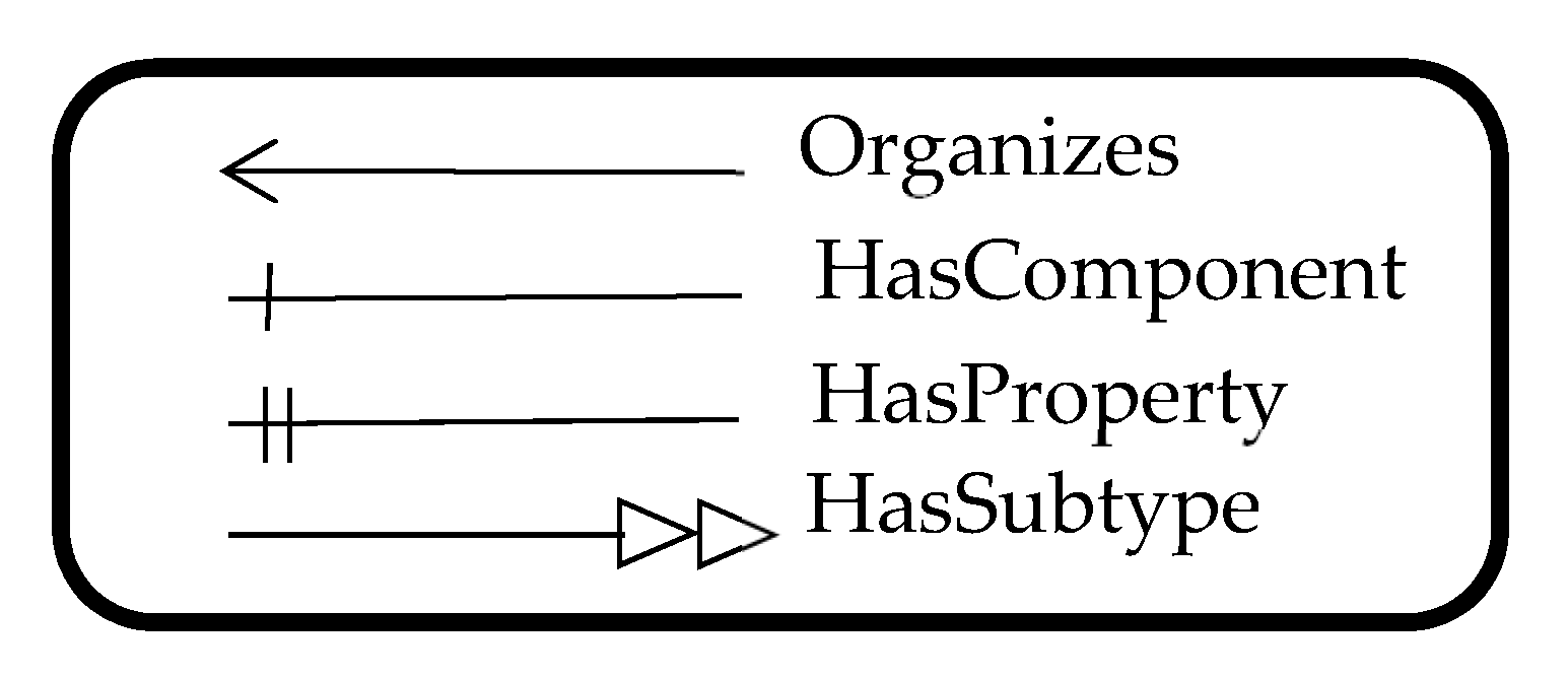
Particular relationships may be defined between OPC UA Nodes; they are called OPC UA References. A Reference connects a source Node to a target Node. The ReferenceType NodeClass is used to define the exact type of each Reference. Among the available types, the following ones will be used in the paper. The HasComponent Reference allows to specify whether an OPC UA Object contains another OPC UA Object or OPC UA DataVariable. Organizes Reference allows to organize OPC UA Nodes inside a folder made up by a FolderType Object. The HasProperty Reference is used to link a source OPC UA Node to a target OPC UA Property; the meaning is that the source Node features a property described by the target Node. HasSubtype expresses a subtype relationship between types.
A very important role is played by the HasModelingRule Reference. For each OPC UA type, the relevant instances may have some mandatory elements (e.g., a particular Object as a component), whilst other elements may be optional (e.g., a certain Property). The HasModelingRule Reference allows to give this information for each OPC UA type defined inside the AddressSpace. The definition of an OPC UA type is realized, specifying the set of Variables and/or Objects (henceforth called InstanceDeclarations), which a generic instance may potentially hold. For each InstanceDeclaration, a HasModelingRule Reference points to a ModelingRule Object as the target Node. The ModelingRule Object specifies whether the relevant InstanceDeclaration is mandatory or not in every instance of an OPC UA type Node. A Mandatory ModelingRule specifies that instances of the OPC UA type must have that InstanceDeclaration. An Optional ModelingRule, instead, specifies that instances of the OPC UA type may have that InstanceDeclaration, but it is not mandatory. The MandatoryPlaceholder and OptionalPlaceholder ModelingRule Objects also exist; the difference with the ModelingRule Objects is that the number of each InstanceDeclaration in each instance may be more than one (e.g., several Objects representing components of a certain type).
3.1.2. OneM2M
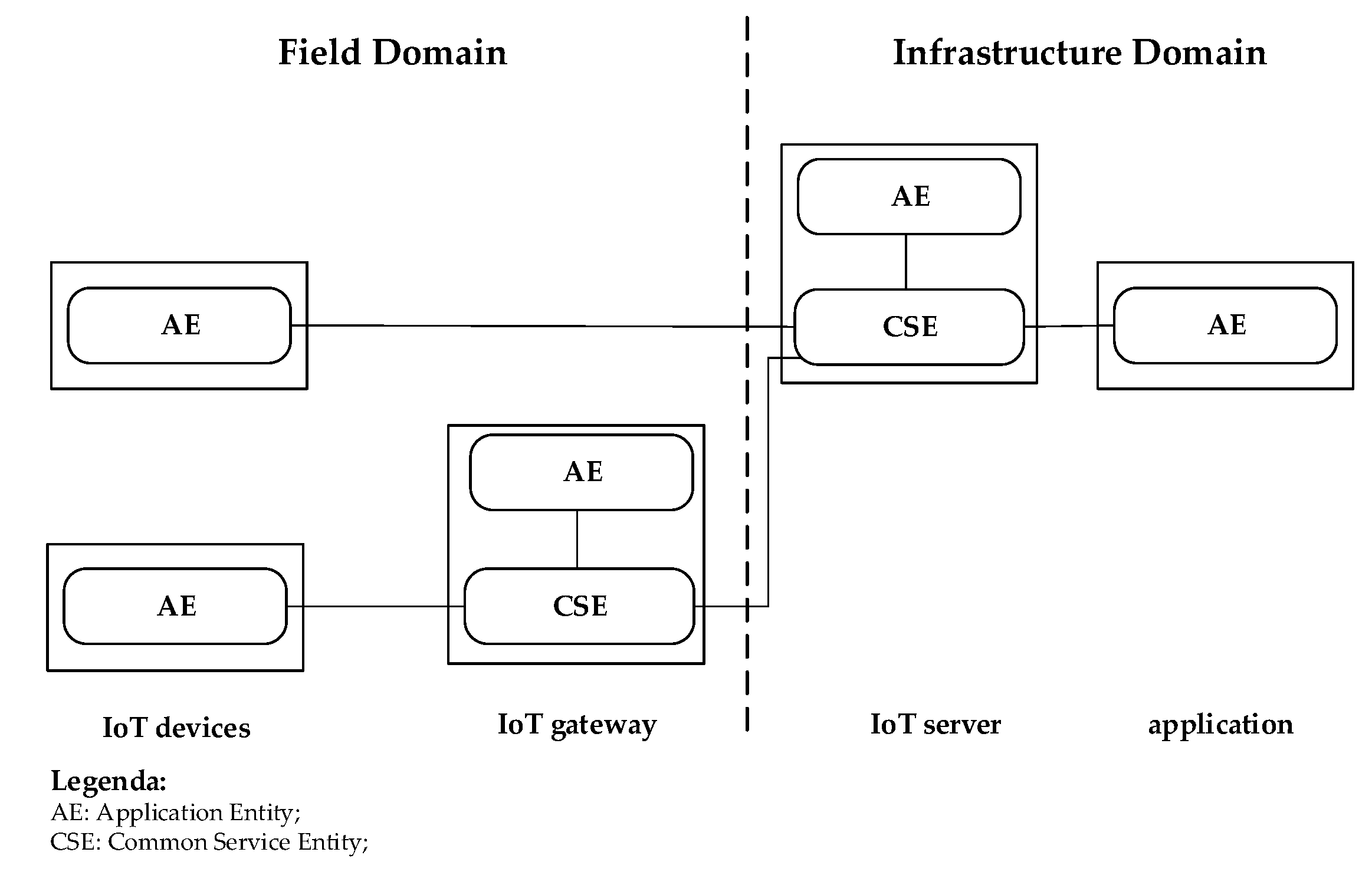
The oneM2M communication system provides interoperability support for IoT technology [18,33,34]. This is realized through a reference architecture model, according to which the IoT environment is divided into two domains: infrastructure and field. The infrastructure domain is the domain in which IoT servers and applications reside. The field domain contains the oneM2M-compliant IoT devices, exchanging data with the servers and applications located at the infrastructure domain; communication with the infrastructure domain may be realized also through one or more IoT gateways located in the Field domain. Figure 3 shows these domains.
The oneM2M reference architecture model is made up by three layers: Application, Common Service and Network Service [33]. Each layer is represented as an entity in the oneM2M system. The Application Entity (AE) represents application services located in a IoT device, IoT gateway, IoT server and application, as shown in Figure 3. Common Service Entity (CSE) represents an instantiation of a set of oneM2M common services; an example is represented by the oneM2M data management services. CSE may be located in an IoT gateway and IoT server, as shown in Figure 3.
The oneM2M architecture adopts the Resource-Oriented Architecture (ROA) model, and thus the services and data that oneM2M system supports are managed and exposed as a resource information model [33,34]. According to the ROA concept, resources can be uniquely addressed by the Uniform Resource Identifier (URI).
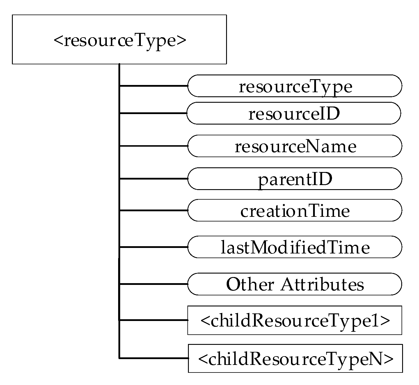
Many resource types are defined in the oneM2M communication system; each of them is made up by a set of mandatory and optional attributes [33]. Among the mandatory attributes (called “universal attributes”) there is the resourceType attribute that identifies the type of resource. Another attribute is resourceID, which is the identifier of the resource; resourceName is the name of the resource used to represent the parent-child relationship. The attribute parentID identifies the parent resource; creationTime is the timestamp of the resource creation. The attribute lastModifiedTime is the timestamp of the last modification of the resource.
The oneM2M system manages its resources through a hierarchical structure. Resources are created as children of other resources. For this reason, each resource features a hierarchical structure made up of attributes and child resources. Figure 4 shows an example of the hierarchical structure of a generic resource; among the attributes shown by the figure, there are the universal attributes as described before.
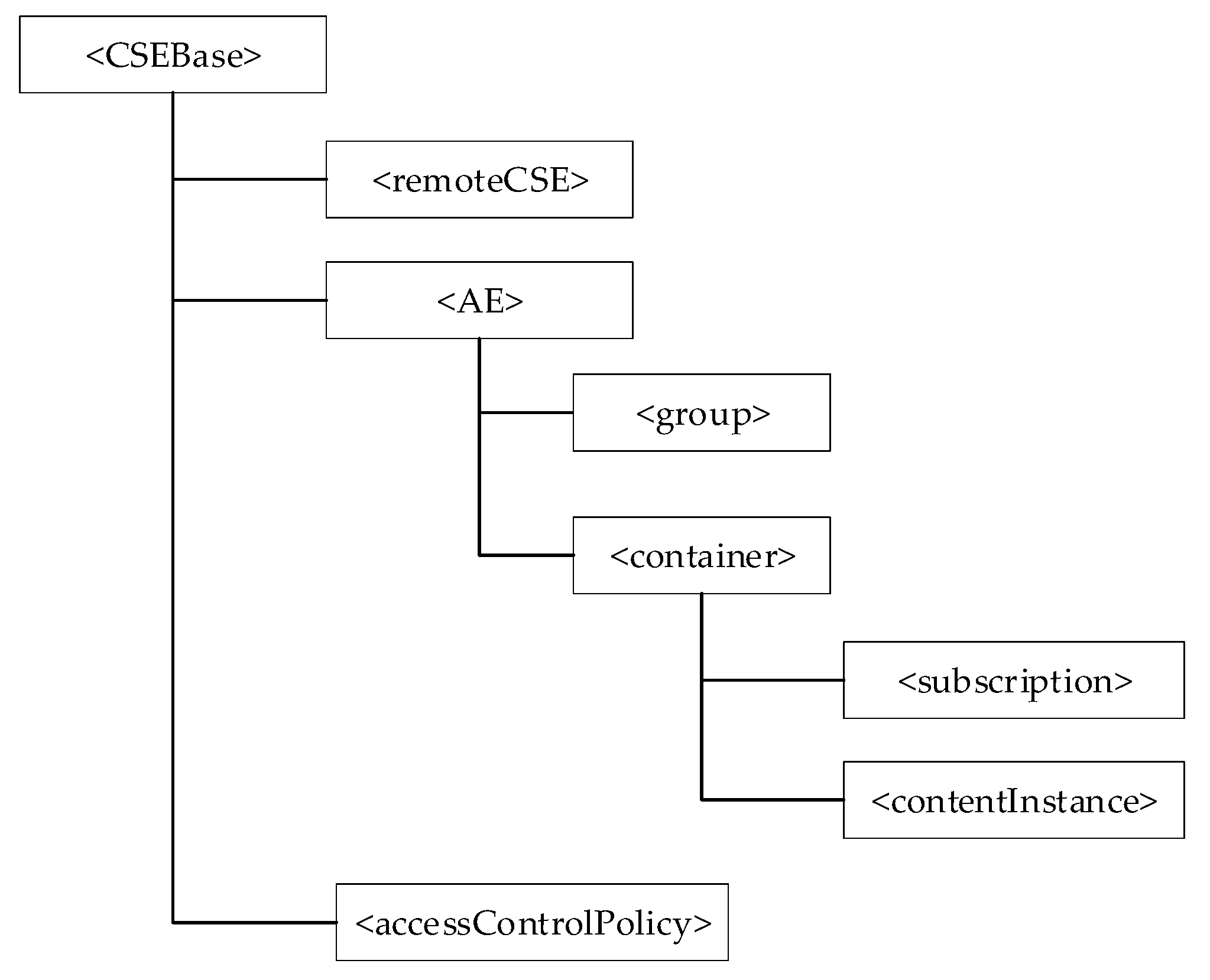
The oneM2M resources are organized in a CSE according to a resource tree whose root is realized by a particular resource of the <CSEBase> type. Figure 5 shows an example of the hierarchical structure of resources inside a CSE.
In the following, the resource types used in the paper will be described in more detail.
A resource of <CSEBase> type represents the root of the resource tree, which organizes the resources inside a CSE, as mentioned before.
In order to expose the oneM2M resources, it is necessary that an AE or a remote CSE was registered in the CSE. This is realized by the creation of a resource of <AE> type or <remoteCSE> type inside the CSE resource tree. According to [33], a CSE where an AE or a remote CSE is registered is called a Registrar CSE. A <remoteCSE> resource type represents a remote CSE that is registered to another CSE. An <AE> resource type represents information about an Application Entity registered to a CSE. Resources of <AE> and <remoteCSE> types are located directly under the <CSEBase> resource of the CSE where it is registered, as shown by Figure 5.
The <container> type allows to represent a container for data instances relevant to a certain AE; it is used to share information with other entities and potentially to track the data. It is created as a child of the <AE> type resource, as shown by Figure 5. The <contentInstance> resource type represents a data instance of the resource of <container> type; it is created as a child of this last kind of resource.
The concept of subscription to resource instances is also specified in oneM2M; it allows efficient monitoring of resource instances and, thus, of the exposed resources. A subscription to a resource in a CSE resource tree allows an entity in the oneM2M architecture to be notified about changes of the subscribed-to resource. The <subscription> resource type represents a subscription to a subscribed-to resource. In order to establish a subscription, a resource of the <subscription> type is created as a child resource of the subscribed-to resource. The <subscription> child resource contains information about the exact scope of the subscription and targets to be notified; in particular, notifications are generated depending on the eventNotificationCriteria set chosen for each <subscription> resource [33]. The full set of criteria available in oneM2M includes the update to attributes of the subscribed-to resource, the deletion of the subscribed-to resource, the creation of a child-resource of the subscribed-to resource, and the deletion of a child-resource of the subscribed-to resource. For example, Figure 5 shows a <container> type resource having a <subscription> type resource as a child; in this case, the creation of the <subscription> resource results in notifications when changes to the parent <container> resource that match with the event notification criteria described by the child <subscription> resource occur.
The <group> resource type represents a group of resources of the same or mixed types.
The <accessControlPolicy> resource (ACP) provides authorization information. A generic resource that requires the application of a particular access control policy may link to the particular ACP specifying this policy.
3.2. Data Access Services
This subsection aims to describe the services available in the two protocols for data access. The understanding of these services is important as the interworking approach here presented makes use of them.
3.2.1. Data Access Services in OPC UA
OPC UA offers many services to allow an OPC UA Client to access the AddressSpace of an OPC UA Server [35]. The simplest access which an OPC UA Client may realize is browsing the AddressSpace of an OPC UA Server by using the OPC UA Browse Service.
The OPC UA Read service is used to read one or more attributes of Nodes. The Write service allows the writing of one or more attributes of Nodes. The values are generally written to the data source; the OPC UA Server will report if it succeeds in the write operation.
Subscriptions and MonitoredItems represent a more sophisticated way to exchange data between the OPC UA Client and Server. They allow an OPC UA Client to receive cyclic updates of OPC UA Variable values and Node attributes. A Subscription is the context needed to realize this cyclic exchange of information; MonitoredItems must be created inside a Subscription by the OPC UA Client and must be associated to OPC UA Nodes.
OPC UA specifications define a particular access control mechanism to the Nodes, based on the idea to separate authentication (determining who a client is) from authorization (determining what the Client is allowed to do). The access control features the concepts of role and permission. A role is the function allowed by a Client when it accesses a Server. For each role, a permission must be defined in OPC UA. RolePermissions is an optional attribute of BaseObjectType; it defines, for a specific Node, the list of permission masks for each role. The permission mask specifies the allowed access to attributes of the Node (e.g., read, write, browse). RolePermissions is an array of RolePermissionType elements, each one made up by the couple {role, permission}, specifying the permission mask available to a specific role [32].
3.2.2. Data Access Services in OneM2M
In the oneM2M protocol, interaction with the resources is supported by the Create, Retrieve, Update, and Delete (CRUD) operations. According to the current version of the oneM2M specifications, CRUD operations may be realized by HTTP methods (i.e., POST, GET, PUT and DELETE) [36], as it will be done in this proposal. In particular, POST is used to map the create operation, GET to map the retrieve one, PUT for the update and DELETE for the delete operation.
In order to understand how the oneM2M standard realizes the access to resources by CRUD operations (and the relevant HTTP methods), Figure 6 shows an example of oneM2M operations on the <contentInstance> type resource. This example was chosen, as the proposal here presented is based on the same data access scheme.
Figure 6 points out the presence of an IoT Server made up by a CSE that maintains a resource tree structure. On the right of the figure, an IoT device is considered; it has been assumed that this device produces information (e.g., temperature values), which must be maintained by the CSE. The AE present in the IoT device must be registered into the CSE in order to be able to reach this goal (for this reason, the CSE in Figure 6 features the tag Registrar CSE). The <AE> resource shown in Figure 6 is created through a registration procedure performed by the AE present in the IoT device. After registration, it is assumed that this AE creates a <container> type resource (with the name Container), representing the component of the IoT device producing the temperature value (e.g., a sensor). Each temperature value is published by the creation of a <contentInstance> type resource containing the new produced value as a child of the Container resource. The HTTP POST Request method is used to create the contentInstance as shown in Figure 6; an HTTP response contains the result of the operation. This procedure is realized for each new value of the Container attributes to be updated.
Figure 6 shows the presence of another AE; it is assumed that it belongs to an Application that aims to consume (i.e., read) each value produced by the IoT device. In order to do this, the following operations must be realized.
The Application AE creates a <subscription> type resource under the Container resource that it is interested in. In this example, it is assumed that the Application AE is interested only in retrieving the updates of the Container resource; the notification criteria for the subscription are properly set according to this aim. The HTTP POST Request is used to map the service finalized to create the subscription. On the basis of this subscription, the CSE will notify the subscribed AE of any new <contentInstance> type resource created under the <container> type resource. Each notification is mapped by a POST Request method as shown in Figure 6; this notification contains the information relevant to the notification (e.g., the new temperature value produced by the IoT sensor).
The oneM2M standard offers a procedure that allows the discovering of resources residing on a CSE resource tree. The use of the Filter Criteria parameter allows limiting the scope of the results. Resource discovery is accomplished by an Originator, which also includes the root of where the discovery begins (e.g., a resource of type <CSEBase>). An Originator could be an AE or another CSE. The unfiltered result of the resource discovery procedure includes all the child resources under the root of where the discovery begins, which the Originator has a Discover access right on [34].
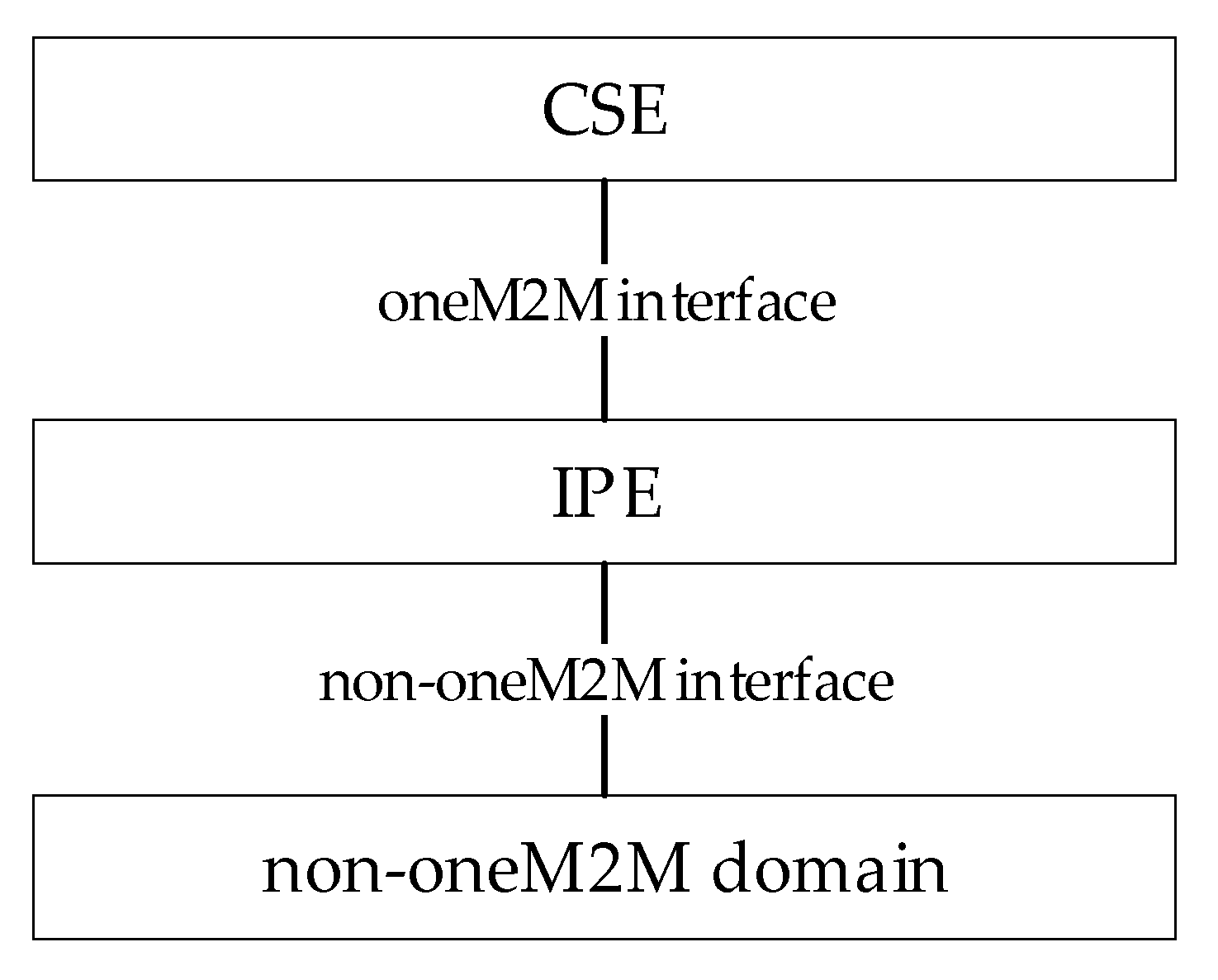
In order to enhance interworking with non-oneM2M domains, oneM2M uses specialized interworking application entities called an Interworking Proxy application Entity (IPE) [37]. An IPE is an AE that supports both oneM2M and non-oneM2M interfaces, as shown in Figure 7. An IPE allows the oneM2M system to interact with any non-oneM2M domain. It has the capability to realize mapping between the specific non-oneM2M information model and oneM2M resources (<AE>, <container>, <flexContainer>, etc.) and to maintain bidirectional communication with the non-oneM2M domain.
4. Methodology
The introduction pointed out that the main goal of the paper is the definition of a solution to make OPC UA and oneM2M interoperable. In particular, it is requested that information produced by oneM2M-based IoT devices could be consumed by OPC UA-based industrial applications. Interoperability implies that the information and the relevant semantics of the teach information produced in the IoT domain may be also available in the OPC UA domain. The methodology adopted in the proposed research work to reach this goal was based on several steps. At the beginning, the analysis of the interoperability solutions available in the current literature were taken into consideration; the most suitable solution was chosen, according to the aim of the work. Then, the definition of a solution was achieved based on the interoperability schema chosen at the previous stage, followed by a software implementation in order to demonstrate the relevant feasibility.
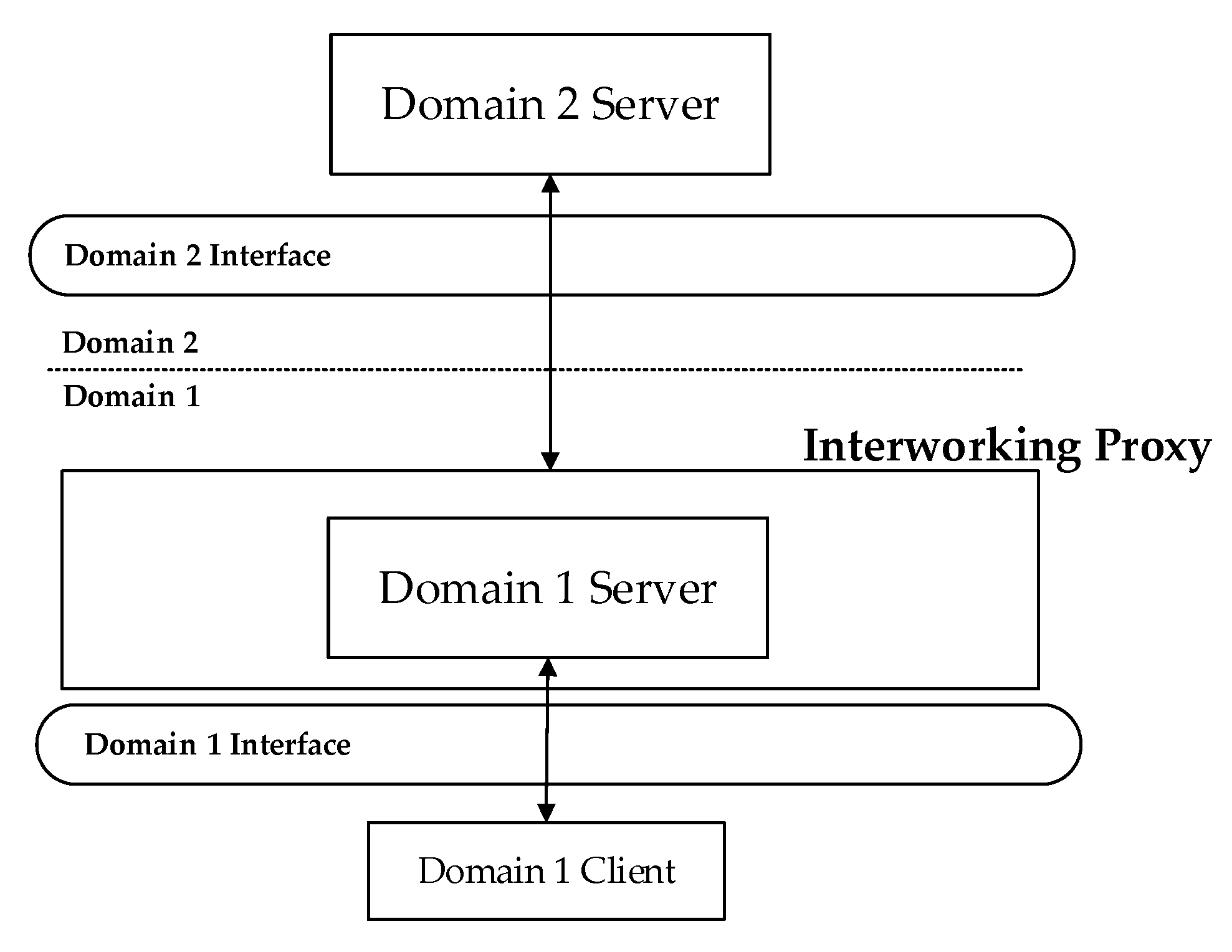
Interoperability in communications protocols is not new; the research dates back to the 1990s with regard to protocol gateways, adapters and other solutions [38]. Among the solutions available in the current literature for the interoperability, there is that based on the use of an interworking proxy. Figure 8 shows an example of an interworking proxy placed between two different communication domains. In both domains, a server maintains a set of information. The Interworking Proxy is in charge of guaranteeing the consistency of this information between the two servers; each time information is updated in the Domain 2 Server, the same update must be reflected in the Domain 1 Server, and vice versa. Consistency is relevant also to the semantic information maintained in the two servers.
As shown in Figure 8, a client may request access to the data maintained by the server of the same domain (e.g., Domain 1 in Figure 8). To this client, it is the server located in the interworking proxy that is providing data. The client is oblivious to the server located in the other domain behind the proxy, which is providing those data. So, an interworking proxy hides the identities and the same existence of servers in the other domain. The data exchange between client and server applications in the same domain occurs using the same interface adopted by the client, without requiring installation of other software.
Considering the aim of the proposed work, the solution shown in Figure 8 and previously described seems very suitable to allow interoperable integration between OPC UA and oneM2M communication protocols in the industrial and IoT domains, respectively. Considering, again, Figure 8, let us assume that Domain 1 is represented by the industrial application domain where an OPC UA Server is available and is accessed by OPC UA client-based industrial applications. Let us assume that Domain 2 is relevant to the oneM2M IoT domain. The interoperability solution shown in Figure 8 allows OPC UA client-based industrial applications to acquire information coming from oneM2M-based IoT devices through an interworking proxy where an OPC UA Server is available. This seem suitable to meet the goal of the paper and for this reason, the interoperability solution shown in Figure 8 will be adopted in this paper.
According to the methodology adopted for this research activity, the interoperability solution shown in Figure 8 has been specialized, focusing on the particular task of realizing interoperability between OPC UA and onM2M. The solution here proposed will be described in Section 6. It required the definition of a mapping process able to realize a correspondence between the information belonging to the two domains (i.e., oneM2M and OPC UA); the next section will describe this mapping process.
5. Mapping OPC UA and OneM2M Information Models
The interworking solution between OPC UA and oneM2M, which will be described in Section 6, required the definition of a mapping process able to realize a one-to-one (or one-to-many, if needed) correspondence between oneM2M resources and OPC UA Nodes in order to map all information (and the relevant semantic) belonging to the oneM2M domain into the OPC UA one. The aim of this section is the description of this mapping process.
Taking into account Figure 4, it is important to recall that each oneM2M resource features both attributes and child-resources. As a general rule, it was assumed that oneM2M attributes are represented by OPC UA Variables of the PropertyType or BaseDataVariableType. Properties are used to map the intrinsic characteristic attributes of resources that generally do not change value, or rarely do. DataVariables are considered to map attributes that change values frequently. The oneM2M child-resources are represented as instances of ad hoc OPC UA ObjectTypes, which are defined in the research carried out, as the native ones were not able to represent some of the oneM2M resources; they will be described in the following.
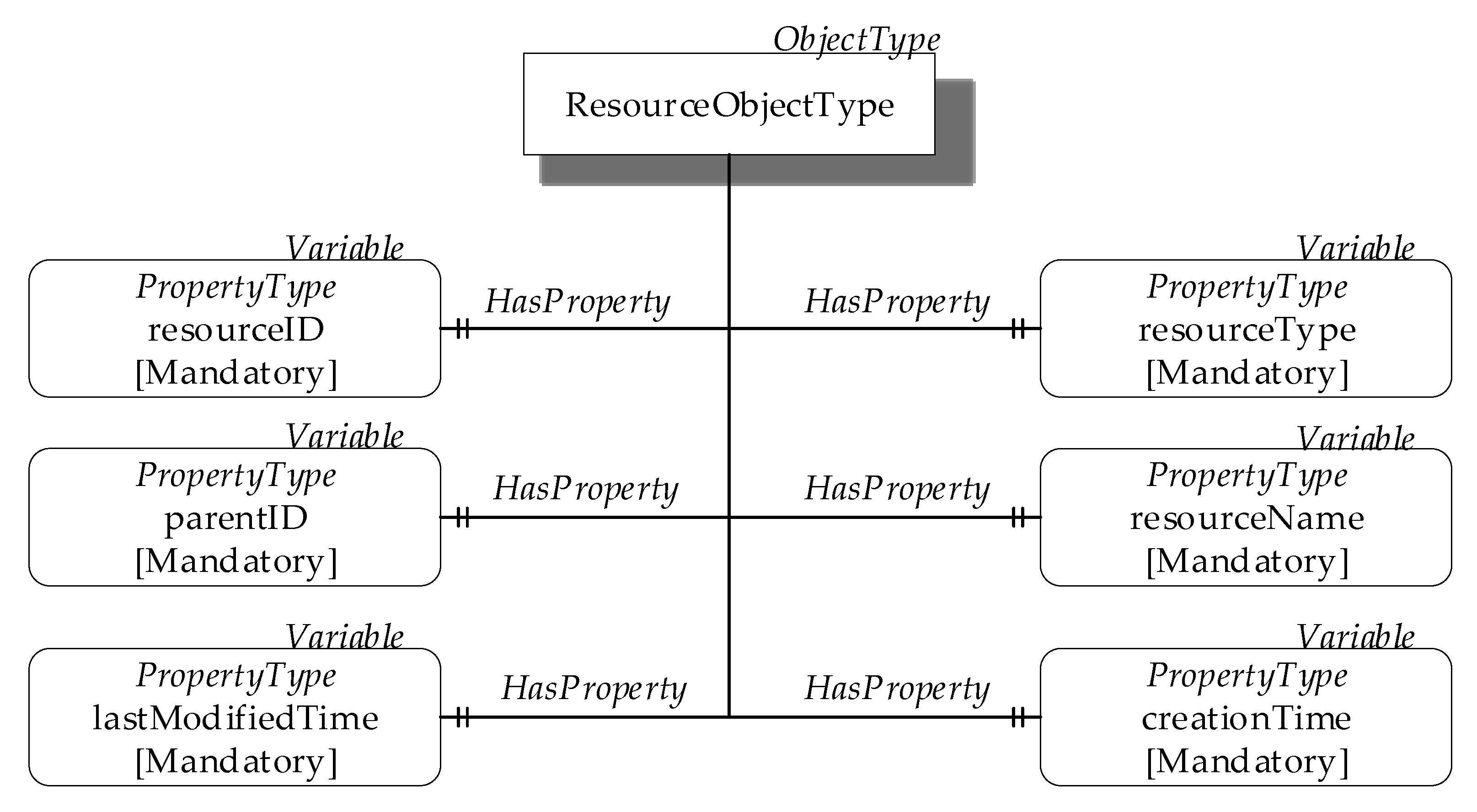
The ResourceObjectType was defined in order to represent the basic structure of a oneM2M resource inside the OPC UA AddressSpace. Figure 9 shows the ResourceObjectType, using OPC UA standard graphical representation. Properties of the ResourceObjectType were defined to represent the attributes of the oneM2M resources. Figure 9 shows the properties representing the “universal attributes” described in Section 3.1.2; Mandatory ModelingRule Objects were used for these properties, as these attributes are mandatory.
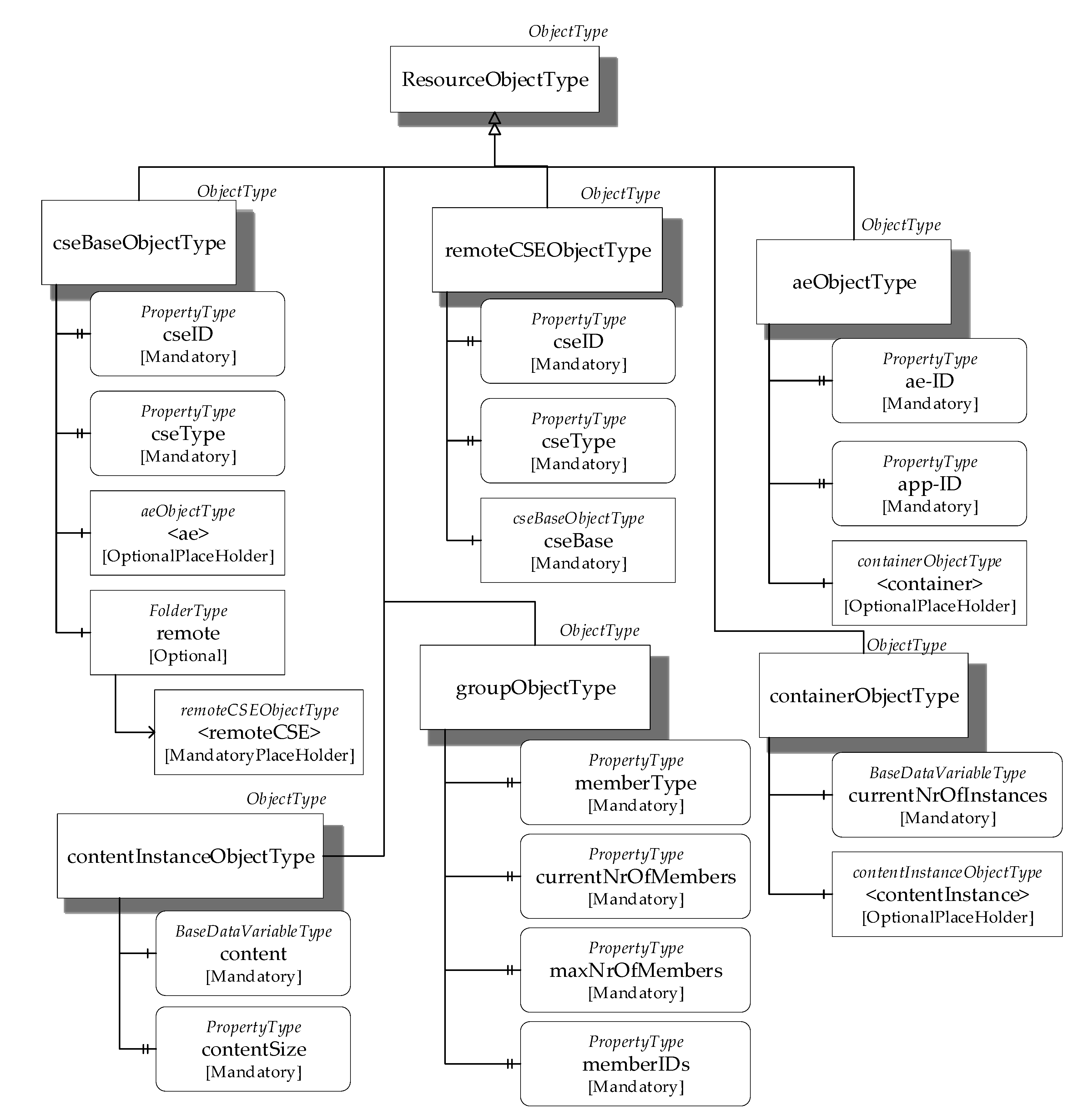
Other OPC UA ObjectTypes were defined, extending the ResourceObjectType with the aim to realize the mapping of each oneM2M resource type. When extending the ResourceObjectType, all the relevant properties are inherited and other Properties and/or Variables are added according to the particular attributes featured by the oneM2M resource to be represented; additional properties or variables are always added using the mechanism based on the OPC UA ModelingRule Object. Figure 10 shows some of the OPC UA ObjectTypes defined to map oneM2M resources.
The cseBaseObjectType represents the oneM2M <CSEBase> resource type. It extends ResourceObjectType, adding other properties among which are cseID and cseType (both mandatory). In the cseID models, the CSE-ID attribute contains the id of the oneM2M CSE [34]. The cseType is another property that maps the oneM2M cseType attribute representing the type of CSE, defined in [34]. The cseBaseObjectType may be made up by one or more Objects of aeObjectType type (described in the following) each of which represents an <AE> resource; for this reason, the <ae> Object featuring an OptionalPlaceHolder Modeling Rule is presented in Figure 10 as a component of the cseBaseObjectType. The cseBaseObjectType may also feature one or more Objects of remoteCSEObjectType (described in the following) each representing an oneM2M <remoteCSE> type resource. A FolderType Object (named remote) was defined to organize the remoteCSEObjectType Objects. If resources of <remoteCSE> type are registered in the CSE resource tree, the FolderType remote Object is present and, in this case, the presence of remoteCSEObjectType Objects modeling these <remoteCSE> type resources is mandatory; this explains the use of the MandatoryPlaceHolder ModelingRule associated to the <remoteCSE> Object, as shown in Figure 10.
The remoteCSEObjectType represents the oneM2M <remoteCSE> resource type, as mentioned. Like cseBaseObjectType, it contains cseID and cseType properties. The <remoteCSE> resource type also features the oneM2M CSEBase attribute, which represents the address of a <CSEBase> resource, relevant to the <remoteCSE> resource [34]. It was represented in OPC UA as an instance of the cseBaseObjectType type, shown in Figure 10 by the InstanceDeclaration cseBase Object.
The contentInstanceObjectType represents the oneM2M <contentInstance> resource type. It holds a Variable as the component, named content, allowing to represent what is contained in the contentInstance. Furthermore, it features a mandatory property named contentSize, representing the size in bytes of the content Variable.
The containerObjectType represents the <container> resource type. It includes two components: the mandatory variable currentNrOfInstance and OptionalPlaceholder contentInstance belonging to the contentInstanceObejctType described before.
The aeObjectType represents the oneM2M <AE> resource type. It extends the ResourceObjectType, adding ae-ID and app-ID as Mandatory Properties; furthermore, it optionally holds as a component one or more container Objects belonging to the containerObjectType described before.
The groupObjectType represents one M2M <group> resource type. It features several properties. The memberType property has a Value that specifies what kinds of resources are members of the group. The currentNrOfMembers property represents the current number of members, whose value cannot exceed the value of maxNrOfMembers (also shown in Figure 10). Finally, there is the memberIDs property, representing a collection of IDs of resources grouped.
The last question to point out is about how oneM2M authorization policy may be mapped into OPC UA. Section 3.1.2 pointed out that the authorization policy is represented in oneM2M through the <accessControlPolicy> resource. The main assumption made in this proposal is that oneM2M authorization policy is realized through the OPC UA RolePermissions attribute, which is present in each of the above defined ObjectTypes (but not shown for space reasons). In particular, for each of the oneM2M resource linked to the <accessControlPolicy> resource, the attribute RolePermissions of the OPC UA Node, representing the oneM2M mapped resource, is set. The setting of this attribute must allow to specify the permissions to be applied for each role defined for the OPC UA clients and for each OPC UA Node as a pair {role, permission}. It is worth noting that roles and permissions may be different in the oneM2M and OPC UA domains; the choice of roles and permissions in the OPC UA domain should be made in such a way to reflect the original ones, as faithfully as possible.
5.1. Case Study
In order to better understand the mapping rules here presented, a very simple example will be presented. Let us assume to map a oneM2M resource of the <container> type into the OPC UA AddressSpace.
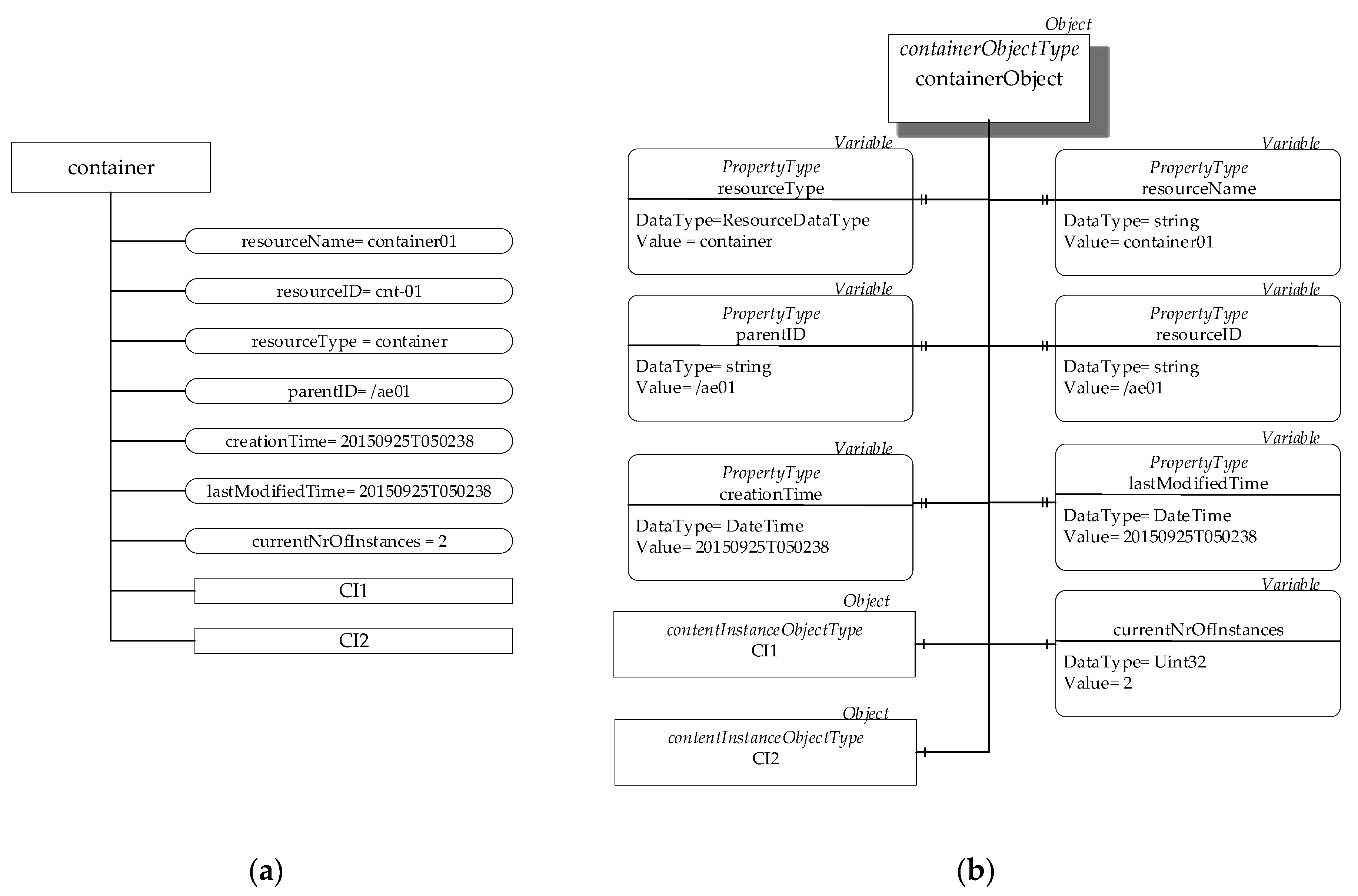
Figure 11a shows the details of the oneM2M resource to be mapped regarding attributes and child-resources. As shown, the values of the attributes are specified; furthermore, it is assumed that two <contentInstance> child-resources are present (i.e., CI1 and CI2 resources).
Figure 11b shows the instance of the OPC UA containerObjectType (seen in Figure 10) created inside the AddressSpace of the OPC UA Server to represent the oneM2M container resource. As can be seen, all the properties inherited from the ResourceObjectType are present in this Object named containerObject; the same values present in the attributes of the oneM2M resource are assigned to the relevant properties of the OPC UA Node. The containerObject features two components represented by contentInstanceObjectType Objects, which map the two child-resources CI1 and CI2 of the <contentInstance> type.
This case study allows to highlight information useful to understand the time complexity of the proposed mapping. Each oneM2M resource is mapped in a OPC UA Node in a time that is independent of the number of oneM2M resources to be mapped; considering this number as the independent variable, the time complexity of the mapping procedure for each single oneM2M resource may be assumed as O (1).
5.2. Software Implementation
The representation of the OPC UA ObjectTypes here proposed for the mapping between oneM2M and OPC UA was implemented, using the eXtensible Markup Language (XML). The choice of this language was because an Information Model implemented into XML can be easily imported into a generic OPC UA Server through common OPC UA Software Development Kits (SDK) and libraries available in the literature.
The XML representation of the OPC UA ObjectTypes here proposed is freely available on GitHub [39] under the file named “onem2m-opcua.xml”, which can be downloaded from this website. This file was prepared using the free tools UAModeler [40], which allow to build a customized OPC UA Information Model and to export it into XML format.
6. Interworking Proposal
The aim of the proposed research is the integration of oneM2M-based IoT devices with OPC UA-compliant industrial applications. An interworking solution is proposed in order to allow OPC UA client-based industrial applications to access information coming from oneM2M-based IoT devices.
The interworking solution between OPC UA and oneM2M here proposed is based on the use of an interworking proxy, according to the scheme shown in Figure 8. It was assumed that the proxy element contains an OPC UA Server accessed by the OPC UA client-based industrial applications; the proxy communicates with an IoT Server placed at the oneM2M infrastructure domain, maintaining in the local CSE all the information relevant to the IoT devices.
The basic stance in this research was to avoid the definition of proprietary solutions to realize the interworking proxy. The use of standard components was instead taken into account. Section 3 points out that oneM2M system foresees the definition of a standard proxy called IPE, which aims to realize the interworking solution between oneM2M and non-oneM2M domains. The interworking solution here proposed was based on the use of this proxy element, specializing it to the specific interworking solution with the OPC UA domain. This specialization will be called OPCUA-IPE in the following.
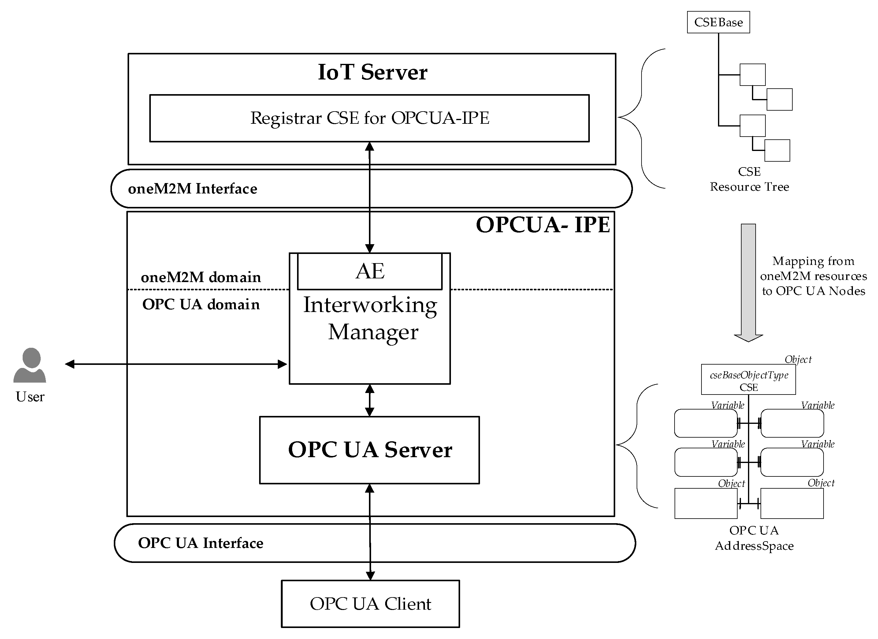
Figure 12 shows the internal architecture of the OPCUA-IPE proposed. Two main entities are present: the Interworking Manager and the OPC UA Server.
The Interworking Manager is the core of the OPCUA-IPE. It communicates with the OPC UA Server and it includes an AE in order to communicate with the IoT Server where a CSE hosts the oneM2M resources to be exposed to the OPC UA domain. The AE must be registered into this CSE. The information flow between AE and the Registrar CSE is realized, using the standard oneM2M interface; in particular, HTTP methods were used in this proposal. It was assumed that the Interworking Manager may receive inputs from a generic external user, as shown in Figure 12; these inputs are limited to information about the choice of the oneM2M resources to be exposed into the OPC UA domain.
The proposed interworking solution is based on the assumption of using an OPC UA Server to expose the resources belonging to the oneM2M system toward the OPC UA domain. In order to reach this aim, the AddressSpace of the OPC UA Server in the IPE maintains OPC UA Nodes, mapping the oneM2M resources belonging to the CSE of the IoT Server in the oneM2M domain. The mapping strategy between OPC UA and oneM2M Information Models presented in Section 5 were used to represent each oneM2M resource by a suitable set of standard or ad hoc defined OPC UA Nodes inside the AddressSpace of the OPC UA Server.
Figure 12 highlights the mapping between oneM2M resources contained in the Registrar CSE of the IoT Server and the OPC UA AddressSpace of the OPC UA Server inside the OPCUA-IPE. According to this solution, each time a generic OPC UA Client application accesses data maintained by the OPC UA Server, it is unaware that the information it is accessing, comes from oneM2M domain. Access by the OPC UA Client is realized through the OPC UA Interface, using the Data Access Services described in Section 3.2.1. Legacy OPC UA Discovery mechanisms may be used by OPC UA clients to find and access the OPC UA Server belonging to the OPCUA-IPE.
The aim of the following subsections is to give more details about the internal activities of the OPCUA-IPE. This description will allow acquiring clear knowledge about the functionalities of each single component of the OPCUA-IPE.
6.1. Operations at Start-Up
Before the OPCUA-IPE may start its activity, suitable procedures must be performed with the aim to expose oneM2M resources in the OPC UA domain.
First of all, the AE inside the Interworking Manager must be registered in the CSE resource tree of the IoT Server; otherwise, any access to the relevant resource cannot be done. As defined in [33], the registration phase involves the creation of an <AE> resource in the CSE resource tree.
Once the registration procedure is complete, the AE has to create a resource of the <subscription> type for each of the CSE resources to be exposed by the OPCUA-IPE in the OPC UA domain. The subscription is needed in order for the AE to be notified about any changes that may occur to the relevant oneM2M resource (e.g., removal of the resource or update of some attributes of the resource); this kind of notification is very important, as each change in the oneM2M resources must be reflected in the AddressSpace of the OPC UA Server.
In order for the Interworking Manager to proceed with realizing these subscriptions through the internal AE, it must be notified about which oneM2M resource must be exposed through the OPC UA Server. As pointed out before, it was assumed that an external user should have the possibility to indicate the list of resources to be mapped inside the OPCUA-IPE. How an external user may give this information to the Interworking Manager may occur in several ways. The oneM2M standard does not provide any mechanisms for the definition of resources to be exposed by an IPE, but the technical specifications [37,41] suggest some methods to this aim; among them is that called Pre-provisioning, which was considered and implemented in this proposal. In the following, details of the procedures needed to realize it inside the OPCUA-IPE will be given.
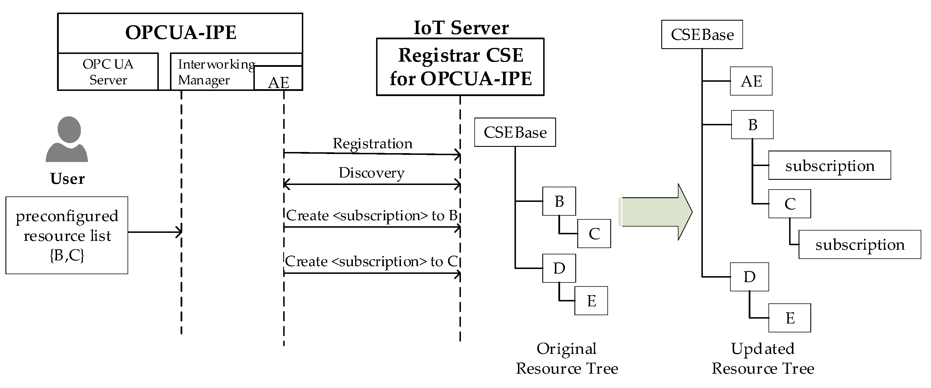
According to the Pre-provisioning method [37,41], the Interworking Manager receives, by the user, the list of resources to be exposed though a preconfigure file. In this case, a discovery process must be conducted by the Interworking Manager with the aim to confirm the presence of the requested resources in the Registrar CSE resource tree. If the resources exist, the Interworking Manager will proceed (through the local AE) to create a resource of the <subscription> resource type for each of the resources contained in the list received, as previously mentioned. Figure 13 shows an example based on this method. In this case, the Interworking Manager is notified about the interest of the user to expose the two resources B and C (through a preconfigured file shown by the same figure). After the registration of the AE and after the discovery procedure, the <subscription> resources are created as children of resources B and C. On the right side of Figure 13, the new Registrar CSE resource tree is shown, after the creation of the <AE> and <subscription> resources.
Once the entire set of oneM2M resources to be exposed into the OPC UA domain are chosen (e.g., {B,C} in the examples of Figure 13), the Interworking Manager will create an instance of the OPC UA Server inside the OPCUA-IPE.
Section 5 described the mapping process able to realize a correspondence between each oneM2M resource and a suitable set of OPC UA Nodes. As mentioned, the “onem2m-opcua.xml” file was defined in this proposal in order to contain the description of the mapping rules. This file is imported by the OPC UA Server in order to create inside the relevant AddressSpace the set of OPC UA types mapping the oneM2M resource types. This import operation is generally done by the same set of libraries available to build an OPC UA Server. For example, the FreeOpcUa libraries [42] here used to implement the OPC UA Server contain the server.import_xml() method able to perform this task. From this moment on, the OPC UA Server will have knowledge of each OPC UA type defined for the mapping from oneM2M to OPC UA.
The next action performed by the Interworking Manager is the population of the OPC UA AddressSpace. For each oneM2M resource to be exposed, the Interworking Manager is in charge of creating an instance of the OPC UA type, modeling the resource type. Once this instance is created for a particular oneM2M resource, the attributes of the Nodes present in the instance must be filled with the same values coming from the oneM2M resource to be exposed. Section 5 showed a very simple example of this procedure (see Figure 11 in Section 5.1).
6.2. Operations at Run-Time
Operations at run-time (started once the activities described in the previous subsections are concluded) mainly consist of accesses made by OPC UA client-based industrial applications to the information maintained by the OPC UA Server. These accesses occur using the OPC UA data access services described in Section 3.2.2. On account of the main hypotheses on which the proposal is based, access to the information maintained in the OPC UA Server means the access to the relevant oneM2M resources of the IoT Server.
Operations at run-time may also involve the execution of suitable procedures in order to guarantee that all information maintained by the OPC UA Server are consistent with the relevant information belonging to the oneM2M domain and vice versa. This means that each time a change occurs in the oneM2M resources, the change must be reflected in the relevant set of OPC UA Nodes representing the oneM2M resource. The same must be realized in the opposite direction.
Changes may be relevant to updates of attribute values of oneM2M resources or OPC UA Nodes. For example, each time a sensor realized by a oneM2M IoT device produces a new value of temperature, the creation of a new <contentInstance> resource containing this value occurs in the CSE of the IoT Server. In the opposite direction, for example, an OPC UA Client may update the attribute value of an OPC UA Node representing an IoT actuator device.
Changes may be also relevant to the modification of the set of oneM2M resources to be exposed to the OPC UA domain; finally, changes may be relevant to the creation or deletion of resources in the Registrar CSE resource tree.
It is required that the Interworking Manager is in charge to take into proper account all the above-mentioned changes and updates both the AddressSpace of the OPC UA Server and the oneM2M resource tree in the Registrar CSE according to the changes occurred. In the following, an analysis of the main updates and the relevant actions carried out by the Interworking Manager will be clearly pointed out.
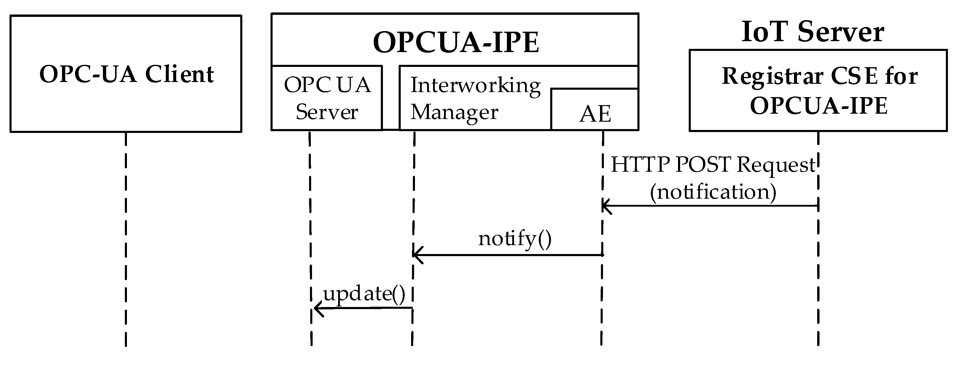
It is important to recall that at the start-up phase, a <subscription> resource is created for each of the exposed resource (as shown in Figure 13, for example). This means that the AE inside the Interworking Manager receives a notification message each time a change in one of the subscribed-to oneM2M resources occurs. Notifications sent to the AE are generated depending on the eventNotificationCriteria set chosen for each <subscription> resource [33]. In this paper, it was assumed that the notification criteria include all the possible updates to a specific resource, foreseen by the oneM2M standard; in particular, they are relevant to the update of attributes of the subscribed-to resource, to the deletion of the subscribed-to resource, to the creation of a child-resource of the subscribed-to resource and to the deletion of a child-resource of the subscribed-to resource.
The Interworking Manager inside the OPCUA-IPE triggers notifications received by the Registrar CSE and makes the relevant update in the AddressSpace of the OPC UA Server. Figure 14 points out the information flow occurring in this case; the HTTP POST Request is sent by the CSE for each update occurred. The notify() request is sent to the Interworking Manager by the local AE for each notification received from Registrar CSE. The update() request is sent to the OPC UA Server as a consequence in order to realize the relevant update.
Update of the AddressSpace depends on the cause of the notification, off course. If an update to the attributes of exposed oneM2M resources occurred, the update of the relevant attributes of the mapping OPC UA Nodes is realized. If a deletion of the subscribed-to resource occurred, the relevant OPC UA Nodes are removed from the AddressSpace. In the case of the creation of a child-resource of the subscribed-to resource, the OPC UA Nodes representing the child-resource are added into the AddressSpace. Finally, in the case of the deletion of a child-resource of the subscribed-to resource, the relevant OPC UA Nodes are removed.
Let us consider another scenario featured by the need to add one or more oneM2M resources at run-time. This may occur when new oneM2M resources are added inside the Registrar CSE resource tree and the user wants to expose them. The scenario may also occur when the user requires exposing oneM2M resources that are already existing (e.g., at the start-up phase) and were not previously exposed. In order to handle this scenario, another method was adopted for the definition of resources to be exposed by an IPE suggested by the technical specifications [37,41]; it is called On-demand Discovery. On-demand Discovery allows dynamically updating the list of resources to be exposed, according to the user’s choice. It was assumed that at run-time, the Interworking Manager repeats the discovery procedure at certain intervals. In this way, it can achieve an update list of the available oneM2M resources, including new oneM2M resources added to the Registrar CSE resource tree; it will communicate this list to the user, in order it can choose the resources to be exposed by the OPCUA-IPE, among the resources present in the list. Adding new exposed oneM2M resources implies the same procedure described in Section 6.1 (i.e., creation of the <subscription> resource for the added oneM2M resource and the creation of the OPC UA Nodes inside the OPC UA Server representing the oneM2M resource to be exposed at run-time).
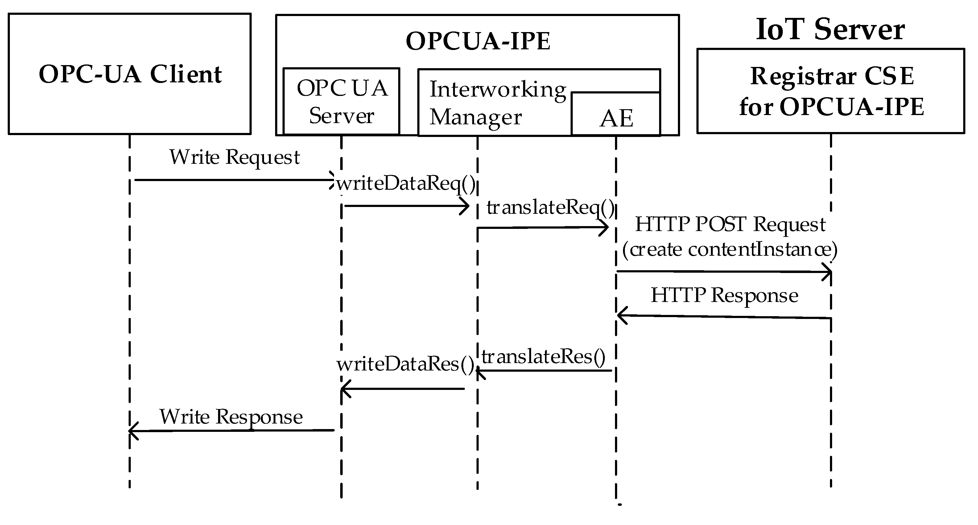
The last scenario, involving the update of information, may occur when an OPC UA Client invokes a OPC UA Write service, requesting the change of one or more attributes of a OPC UA Node modeling oneM2M exposed resources. In this case, the new value must be published in the Register CSE, using the mechanism based on the <contentInstance> resource, explained in Section 3.2.2 (see Figure 6). Figure 15 shows the interworking procedure defined in this work and applied for by each Write Request sent by an OPC UA Client. The OPC UA Server will issue an internal request (i.e., writeDataReq()) to the Interworking Manager, which will request the AE transmission of a HTTP POST Request to create a <contentInstance> resource, containing the attribute value updated by the Write service. The Interworking Manager invokes an ad hoc defined internal service (i.e., translateReq()) to make this request, specifying the URI of the oneM2M resource to be accessed. On the receipt of the relevant HTTP Response, the Interworking Manager will confirm the writing operation to the OPC UA Server by the writeDataRes(). The OPC UA Client will receive a Write Response sent by the OPC UA Server confirming its pending Write Request.
7. OPCUA-IPE Software Implementation
The OPCUA-IPE presented in this paper was implemented and the source code is freely available on GitHub [43]. Implementation was based on the Python language, chosen mainly to allow an easier integration with libraries and the SDK used to realize some elements of the OPCUA-IPE architecture.
Implementation of the AE inside the Interworking Manager was based on OpenMTC SDK [44]; OpenMTC is a Python-based reference implementation of the oneM2M standard. A new class was created, extending from the base class XAE [44], which is in charge of providing resource discovery, subscription and resource management. The extension of this class mainly allows the AE to perform several activities of the interworking procedure described in Section 6; the main activities implemented are the registration of AE to the CSE, discovery of the entire resource tree of the Registrar CSE, creation of <subscription> resources inside the Registrar CSE resource tree, management of each notification received from the registered resources of the Registrar CSE (see notify() in Figure 14), and management of translateReq() and translateRes() internal services exchanged between the Interworking Manager and AE, and their mapping to the HTTP messages exchanged with the CSE (see Figure 15).
The Interworking Manager is the core of the architecture, as previously mentioned. It was developed in Python as a new class. This class is in charge of creating an instance of the OPC UA Server to populate the AddressSpace with the Nodes mapping oneM2M resources to realize the translateReq() and translateRes() internal services (see Figure 15), and to realize the updates of the AddressSpace for each notification received from the AE (update() in Figure 14).
Implementation of OPC UA Server is based on FreeOpcUa [42], a Python-based open-source OPC UA communication stack. Some classes of the FreeOpcUa libraries were extended in order to realize the interworking procedures described in Section 6. Furthermore, the UaExpert OPC UA Client [45] was used during the test carried out in this research.
8. Case Study
The aim of this section is to give an example of the application of the interworking proposal presented. A simple case study was taken into consideration in order to be easily understood. A graphical overview of the case study is shown in Figure 16.
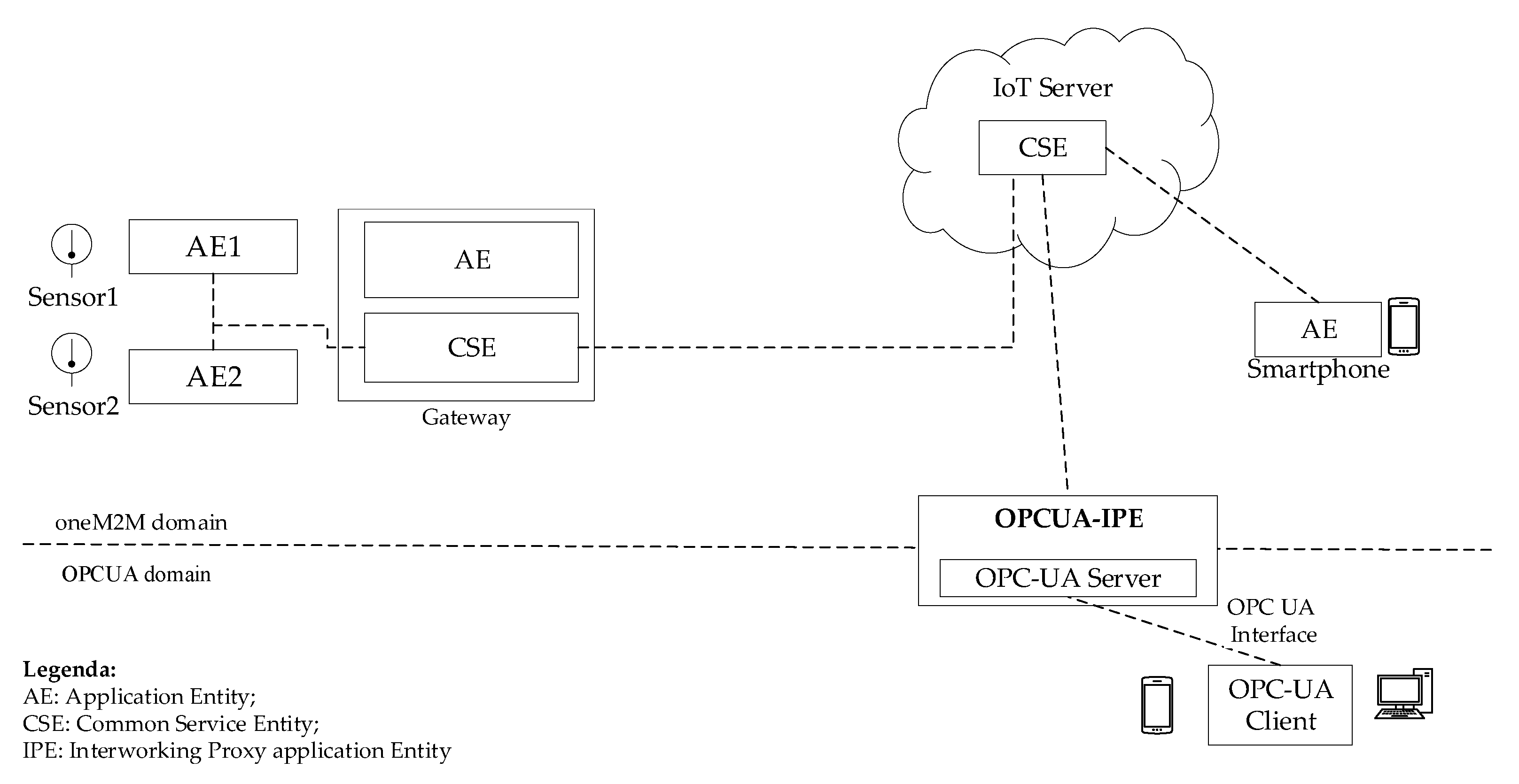
The scenario deals with a oneM2M system that can be remotely monitored by a user’s smartphone. Two IoT temperature sensors are attached to a Gateway, which communicates with a cloud IoT Server in the infrastructure domain. The cloud service platform supports a set of services to allow the smartphone to acquire the temperature values. To reach this aim, the smartphone hosts an application used for the actual monitoring; in particular, the AE inside the smartphone is an embedded application with capabilities to interact directly with the oneM2M cloud service platform.
AE1 and AE2 in Figure 16 are applications embedded in the Sensor1 and Sensor2 IoT devices at the field domain, respectively; they have the capabilities to read the temperature values and update these values in the CSE of the Gateway.
Two CSEs are present in the system. An CSE is hosted in the cloud by the oneM2M IoT Server and a CSE is hosted by the Gateway. The CSE located in the Cloud Service Platform interacts with the CSE in the Gateway, allowing the remote acquisition of the temperature values coming from the two IoT sensors.
Figure 16 points out the presence of the OPCUA-IPE proposed in this paper to realize interworking from oneM2M to OPC UA. In particular, it was assumed the existence of OPC UA client-based applications, which may have the need to acquire the information produced by the two IoT, oneM2M-based sensors shown in Figure 16. OPCUA-IPE is connected to the CSE of the IoT Server in the oneM2M infrastructure domain.
Figure 17 shows the CSE resource tree maintained by the IoT Server. As it is shown, the resource tree starts with a <CSEBase> resource named server and two child-resources, a <remoteCSE> named gateway and an <AE> named smartphone_ae, relevant to the Gateway and smartphone applications, respectively. The Figure 17 gives details only to the resources relevant to the Gateway, as the aim of this case study is the integration of IoT devices (i.e., Sensor1 and Sensor2) into industrial applications.
As can be seen, the resource tree under the child-resource gateway is made up of the “universal attributes” and the child-resources described in the following. There is an <accessControlPolicy> resource named gateway_acp; the two <AE> resources named sensor_ae1 and sensor_ae2 refer to the two temperature sensors shown in Figure 16. It was assumed that the first temperature system (i.e., Sensor1) features only one data instance (i.e., CI1), whilst Sensor2 features two data instances (i.e., CI1 and CI2). For this reason, sensor_ae1 contains a <container> child-resource named sensor, featuring only the <contentInstance> resource, named CI1. The other <AE> resource named sensor_ae2, contains another <container> child-resource named sensor, featuring the two <contentInstance> resources, named CI1 and CI2.
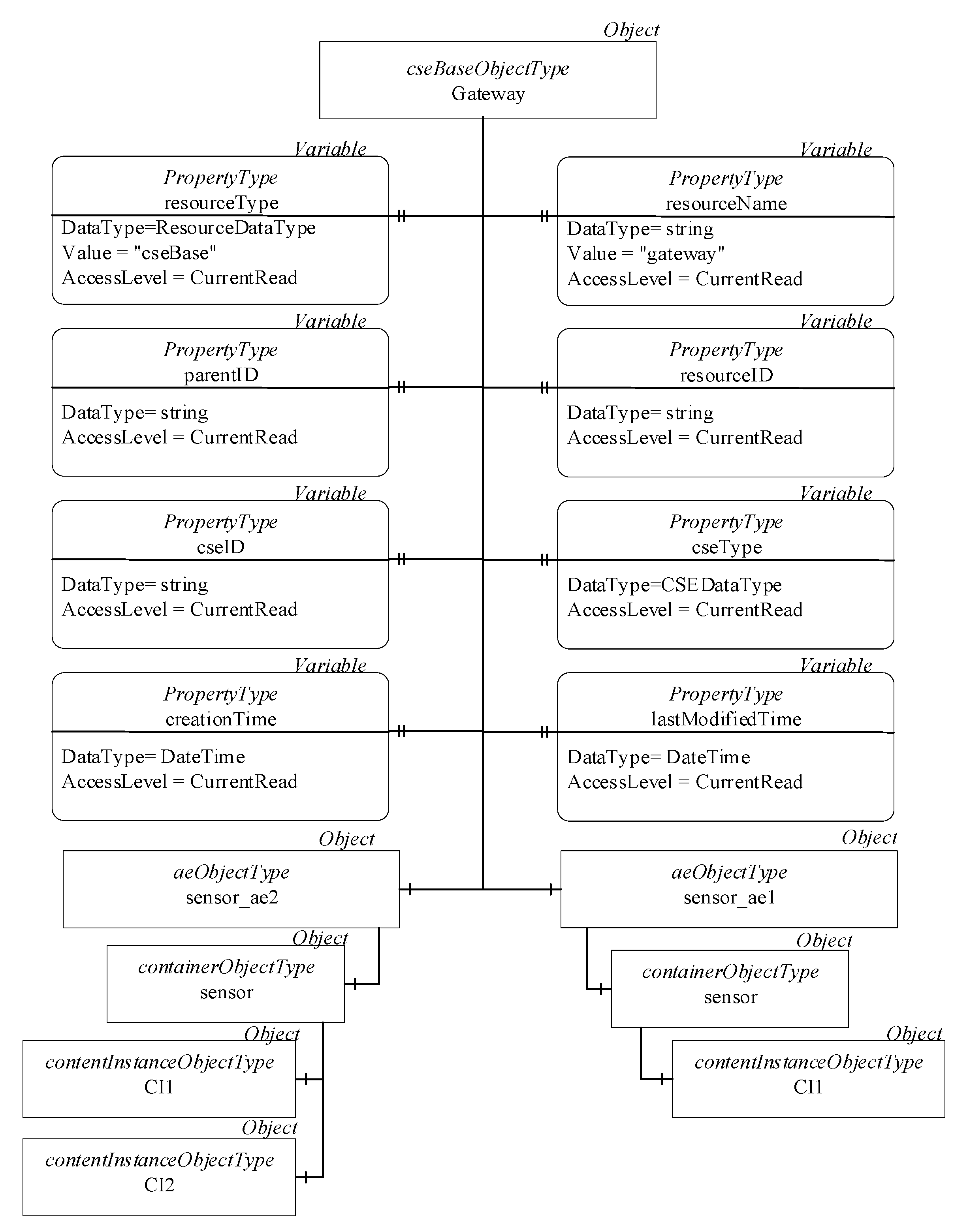
According to the proposal here presented, the OPC UA client-based industrial applications access the OPC UA Server inside the OPCUA-IPE to get information relevant to the actual temperature values of the two sensors shown in Figure 16. In order to achieve this aim, mapping between oneM2M resources inside the IoT Server CSE and the AddressSpace of the OPC UA Server must be realized. Figure 18 shows only the mapping of the gateway child-resource tree to the AddressSpace of the OPC UA Server inside the OPCUA-IPE. The figure shows the OPC UA Nodes used in the mapping, giving few details in terms of their attributes only due to the lack of space. The mapping was realized according to the process described in Section 5. Gateway Object is an instance of cseBaseObjectType, mapping the gateway child-resource. This Object features two components; they are the two instances of aeObjectType named sensor_ae1 and sensor_ae2, mapping the relevant <AE> resources. The Objects, named sensor, map the relevant <container> resources; Objects CI1 and CI2 map the <contentInstance> resources with the same name. As mentioned in Section 5, the <gateway_acp> resource is not mapped into the OPC UA Server, as this mapping is realized by the definition of suitable roles and permissions inside the server in order to model the attribute privileges of the <gateway_acp> resource.
9. Final Remarks
This paper presented an interworking proposal between OPC UA and oneM2M, which enables the access of information maintained by the oneM2M domain to applications based on OPC UA. This has the advantage of enhancing interoperability inside Industry 4.0, where a very strong requirement is the integration of industrial applications with IoT domains. The paper is original, as no other contributions are present in the current literature with the same subject.
The author believes that interworking between OPC UA and oneM2M protocols is important, as they are considered strategic communication frameworks in Industry 4.0 reference architectures. In particular, the reference architecture defined by the Industrial Internet Consortium includes both of them as prominent connectivity standards for the framework layer of the Industrial Internet Reference Architecture [15]. According to [15], the OPC UA and oneM2M are alternative frameworks and no interoperable solution is mentioned to realize interworking between them. The solution here presented may allow to improve the importance of both standards inside the reference architecture [15], thanks to the proposed interoperability.
A last consideration must be given regarding the limitation of the proposed research, which considers the interoperability only from the oneM2M domain toward the OPC UA domain and not in the opposite direction. This limitation may be easily overcome considering the existing solution [27,28] cited in Section 2, which defines the interoperable solution in the opposite direction. A suggestion for future research could be the merging of the two proposals in order to achieve an interoperable solution in both directions.
Funding
This research was partially funded by University of Catania, PIA.CE.RI. 2020-2022 Line 2—GOSPEL Project, grant number 61722102132, Principal investigator A. Costa.
Institutional Review Board Statement
Not applicable in this work.
Informed Consent Statement
Not applicable in this work.
Data Availability Statement
Not applicable. No data.
Acknowledgments
Special thanks to Salvatore Mulé for the technical support on oneM2M standard and to Marco Giuseppe Salafia for the technical support on OPC UA standard.
Conflicts of Interest
The author declares no conflict of interest.
References
- Melo, P.F.S.; Godoy, E.P.; Ferrari, P.; Sisinni, E. Open Source Control Device for Industry 4.0 Based on RAMI 4.0. Electronics 2021, 10, 869. [Google Scholar] [CrossRef]
- Ejsmont, K.; Gladysz, B.; Kluczek, A. Impact of Industry 4.0 on Sustainability—Bibliometric Literature Review. Sustainability 2020, 12, 5650. [Google Scholar] [CrossRef]
- Butt, J. A Strategic Roadmap for the Manufacturing Industry to Implement Industry 4.0. Designs 2020, 4, 11. [Google Scholar] [CrossRef]
- Pivoto, D.G.S.; de Almeida, L.F.F.; da Rosa Righi, R.; Rodrigues, J.J.P.C.; Baratella Lugli, A.; Alberti, A.M. Cyber-physical systems architectures for industrial internet of things applications in Industry 4.0: A literature review. J. Manuf. Syst. 2021, 58, 176–192. [Google Scholar] [CrossRef]
- Ungurean, I.; Gaitan, N.C. A Software Architecture for the Industrial Internet of Things—A Conceptual Model. Sensors 2020, 20, 5603. [Google Scholar] [CrossRef] [PubMed]
- Hassan, R.; Qamar, F.; Hasan, M.K.; Aman, A.H.M.; Ahmed, A.S. Internet of Things and Its Applications: A Comprehensive Survey. Symmetry 2020, 12, 1674. [Google Scholar] [CrossRef]
- Durana, P.; Perkins, N.; Valaskova, K. Artificial Intelligence Data-driven Internet of Things Systems, Real-Time Advanced Analytics, and Cyber-Physical Production Networks in Sustainable Smart Manufacturing. Econ. Manag. Financ. Mark. 2021, 16, 20–30. [Google Scholar] [CrossRef]
- Tucker, G. Sustainable Product Lifecycle Management, Industrial Big Data, and Internet of Things Sensing Networks in Cyber-Physical System-based Smart Factories. J. Self Gov. Manag. Econ. 2021, 9, 9–19. [Google Scholar] [CrossRef]
- Watkins, D. Real-Time Big Data Analytics, Smart Industrial Value Creation, and Robotic Wireless Sensor Networks in Internet of Things-based Decision Support Systems. Econ. Manag. Financ. Mark. 2021, 16, 31–41. [Google Scholar] [CrossRef]
- Lăzăroiu, G.; Kliestik, T.; Novak, A. Internet of Things Smart Devices, Industrial Artificial Intelligence, and Real-Time Sensor Networks in Sustainable Cyber-Physical Production Systems. J. Self Gov. Manag. Econ. 2021, 9, 20–30. [Google Scholar] [CrossRef]
- Nica, E.; Stan, C.I.; Luțan, A.G.; Oa, R.-Ș. Internet of Things-based Real-Time Production Logistics, Sustainable Industrial Value Creation, and Artificial Intelligence-driven Big Data Analytics in Cyber-Physical Smart Manufacturing Systems. Econ. Manag. Financ. Mark. 2021, 16, 52–62. [Google Scholar] [CrossRef]
- Riley, C.; Vrbka, J.; Rowland, Z. Internet of Things-enabled Sustainability, Big Data-driven Decision-Making Processes, and Digitized Mass Production in Industry 4.0-based Manufacturing Systems. J. Self Gov. Manag. Econ. 2021, 9, 42–52. [Google Scholar] [CrossRef]
- Adolphs, P.; Bedenbender, H.; Dirzus, D.; Ehlich, M.; Epple, U.; Hankel, M.; Heilde, R.; Hoffmeister, M.; Huhle, H.; Karcher, B.; et al. Reference Architecture Model Industrie 4.0 (RAMI 4.0). Status Report. VDI/VDE and ZVEI. July 2015. Available online: https://www.zvei.org/fileadmin/user_upload/Themen/Industrie_4.0/Das_Referenzarchitekturmodell_RAMI_4.0_und_die_Industrie_4.0-Komponente/pdf/5305_Publikation_GMA_Status_Report_ZVEI_Reference_Architecture_Model.pdf (accessed on 17 May 2021).
- Bangemann, T.; Bauer, C.; Bedenbender, H.; Diesner, M.; Epple, U.; Elmas, F.; Friedrich, J.; Goldschimidt, T.; Gobe, F.; Gruner, S.; et al. Industrie 4.0—Technical Assets: Basic Terminology Concepts, Life Cycles and Administration Models. Status Report. VDI/VDE and ZVEI. March 2016. Available online: https://www.vdi.de/ueber-uns/presse/publikationen/details/industrie-40-technical-assets-basic-terminology-concepts-life-cycles-and-administration-models-english-version (accessed on 17 May 2021).
- Industrial Internet Consortium. The Industrial Internet of Things, Volume G5: Connectivity Framework. Available online: https://www.iiconsortium.org/pdf/IIC_PUB_G5_V1.01_PB_20180228.pdf (accessed on 17 May 2021).
- Mahnke, W.; Leitner, S.H.; Damm, M. OPC Unified Architecture; Springer: Berlin/Heidelberg, Germany, 2009. [Google Scholar]
- Vogel, B.; Kajtazi, M.; Bugeja, J.; Varshney, R. Openness and Security Thinking Characteristics for IoT Ecosystems Information. Information 2020, 11, 564. [Google Scholar] [CrossRef]
- Swetina, J.; Lu, G.; Jacobs, P.; Ennesser, F.; Song, J. Toward a standardized common M2M service layer platform: Introduction to oneM2M. IEEE Wirel. Commun. 2014, 21, 20–26. [Google Scholar] [CrossRef]
- Candido, G.; Jammes, F.; de Oliveira, J.B.; Colombo, A.W. Soap at device level in the industrial domain: Assessment of OPC UA and DPWS specifications. In Proceedings of the 8th IEEE International Conference on Industrial Informatics, Osaka, Japan, 13–16 July 2010; pp. 598–603. [Google Scholar]
- Sauter, T.; Lobashov, M. How to access factory floor information using internet technologies and gateways. IEEE Trans. Ind. Inform. 2011, 7, 699–712. [Google Scholar] [CrossRef]
- Izaguirre, M.; Martinez Lastra, J.L.; Lobov, A. OPC-UA and DPWS interoperability for factory floor monitoring using complex event processing. In Proceedings of the 9th IEEE International Conference on Industrial Informatics, Lisbon, Portugal, 26–29 July 2011; pp. 205–211. [Google Scholar]
- Grüner, S.; Pfrommer, J.; Palm, F. A restful extension of OPC UA. In Proceedings of the IEEE World Conference on Factory Communication Systems (WFCS 2015), Palma de Mallorca, Spain, 27–29 May 2015; pp. 1–4. [Google Scholar]
- Grüner, S.; Pfrommer, J.; Palm, F. Restful industrial communication with OPC UA. IEEE Trans. Ind. Inform. 2016, 12, 1832–1841. [Google Scholar] [CrossRef]
- Wang, P.; Pu, C.; Wang, H. OPC UA Message Transmission Method over CoAP. Available online: https://tools.ietf.org/html/draft-wang-core-opcua-transmission-01 (accessed on 17 May 2021).
- Derhamy, H.; Rönnholm, J.; Delsing, J. Protocol interoperability of OPC UA in service oriented architectures. In Proceedings of the 15th IEEE International Conference on Industrial Informatics (INDIN), Emden, Germany, 24–26 July 2017; pp. 44–50. [Google Scholar]
- Wang, Y.; Pu, C.; Wang, P.; Wu, J. A CoAP-based OPC UA Transmission Scheme for Resource-Constrained Devices. In Proceedings of the 2020 Chinese Automation Congress (CAC), Shanghai, China, 6–8 November 2020. [Google Scholar]
- oneM2M. TR-0018-V-4.0.0: Industrial Domain Enablement. Available online: http://member.onem2m.org/Application/documentapp/downloadLatestRevision/default.aspx?docID=29334 (accessed on 17 May 2021).
- Lai, P.; Lin, F.J. Industrial Internet of Things Interoperability Between OPC UA and OneM2M. In International Conference on Internet of Things as a Service; Li, B., Zheng, J., Fang, Y., Yang, M., Yan, Z., Eds.; Lecture Notes of the Institute for Computer Sciences, Social Informatics and Telecommunications Engineering; Springer: Cham, Germany, 2020; Volume 316, pp. 439–455. [Google Scholar]
- Cavalieri, S.; Mulè, S.; Salafia, M.G. Enabling OPC UA and oneM2M Interworking. In Proceedings of the IEEE International Conference on Industrial Technologies (ICIT 2020), Buenos Aires, Argentina, 26–28 February 2020. [Google Scholar]
- Cavalieri, S.; Mulè, S. Towards Interoperability of oneM2M and OPC UA. In Proceedings of the International Conference on Enterprise Information System (ICEIS 2020), Prague, Czech Republic, 5–7 May 2020. [Google Scholar]
- Pras, A.; Schoenwaelder, J. On the Difference between Information Models and Data Models. Internet Engineering Task Force, RFC 3444. January 2003. Available online: https://tools.ietf.org/html/rfc3444 (accessed on 17 May 2021).
- OPC Foundation. Part 3: Address Space Model. Available online: https://opcfoundation.org/developer-tools/specifications-unified-architecture/part-3-address-space-model (accessed on 17 May 2021).
- oneM2M. TS-0001-V4.10.0: Functional Architecture. Available online: http://member.onem2m.org/Application/documentapp/downloadLatestRevision/default.aspx?docID=31839 (accessed on 17 May 2021).
- oneM2M. TS-0004-V4.4.0: Service Layer Core Protocol. Available online: http://member.onem2m.org/Application/documentapp/downloadLatestRevision/default.aspx?docID=31772 (accessed on 17 May 2021).
- OPC Foundation. Part 4: Services. Available online: https://opcfoundation.org/developer-tools/specifications-unified-architecture/part-4-services (accessed on 17 May 2021).
- oneM2M. TS-0009-V3.6.0: HTTP Protocol Binding. Available online: http://member.onem2m.org/Application/documentapp/downloadLatestRevision/default.aspx?docID=31202 (accessed on 17 May 2021).
- oneM2M. TS-0033-V3.0.0: Interworking Framework. Available online: http://member.onem2m.org/Application/documentapp/downloadLatestRevision/default.aspx?docID=29581 (accessed on 17 May 2021).
- Derhamy, H.; Eliasson, J.; Delsing, J. IoT Interoperability—On-Demand and Low Latency Transparent Multiprotocol Translator. IEEE Internet Things J. 2017, 4, 1754–1763. [Google Scholar] [CrossRef]
- oneM2M-to-OPCUA-Information-Models-mapping. Available online: https://github.com/OPCUAUniCT/oneM2M-to-OPCUA-Information-Models-mapping (accessed on 17 May 2021).
- UaModeler. Available online: https://www.unified-automation.com/products/development-tools/uamodeler.html (accessed on 17 May 2021).
- oneM2M. TS-0024 V3.2.2: OCF Interworking. Available online: http://member.onem2m.org/Application/documentapp/downloadLatestRevision/default.aspx?docID=29565 (accessed on 17 May 2021).
- FreeOpcUa. Available online: https://github.com/FreeOpcUa/python-opcua (accessed on 17 May 2021).
- oneM2M-OPCUA-IPE. Available online: https://github.com/OPCUAUniCT/oneM2M-OPCUA-IPE (accessed on 17 May 2021).
- OpenMTC. Available online: https://www.openmtc.org/index.html (accessed on 17 May 2021).
- Unified Automation. UaExpert-A Full-Featured OPC UA Client. Available online: https://www.unified-automation.com/products/development-tools/uaexpert.html (accessed on 17 May 2021).
Figure 1.
Standard graphical representation of Nodes in OPC UA.
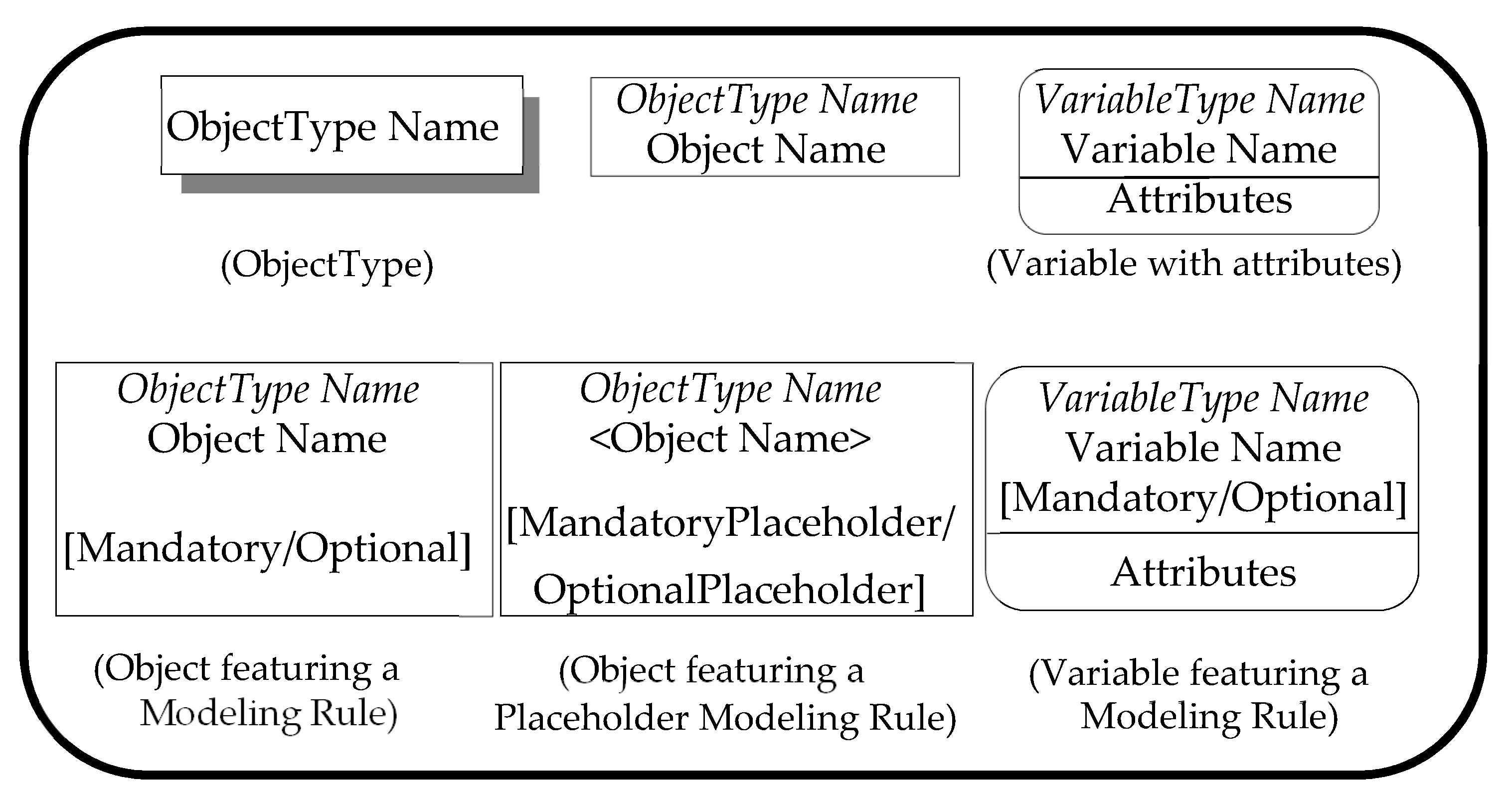
Figure 2.
Standard graphical representation of References in OPC UA.

Figure 3.
oneM2M infrastructure and field domains.

Figure 4.
Hierarchical structure of a generic oneM2M resource.

Figure 5.
Hierarchical structures of oneM2M resources: CSE resource tree.

Figure 6.
Example of oneM2M data access, using HTTP method mapping.
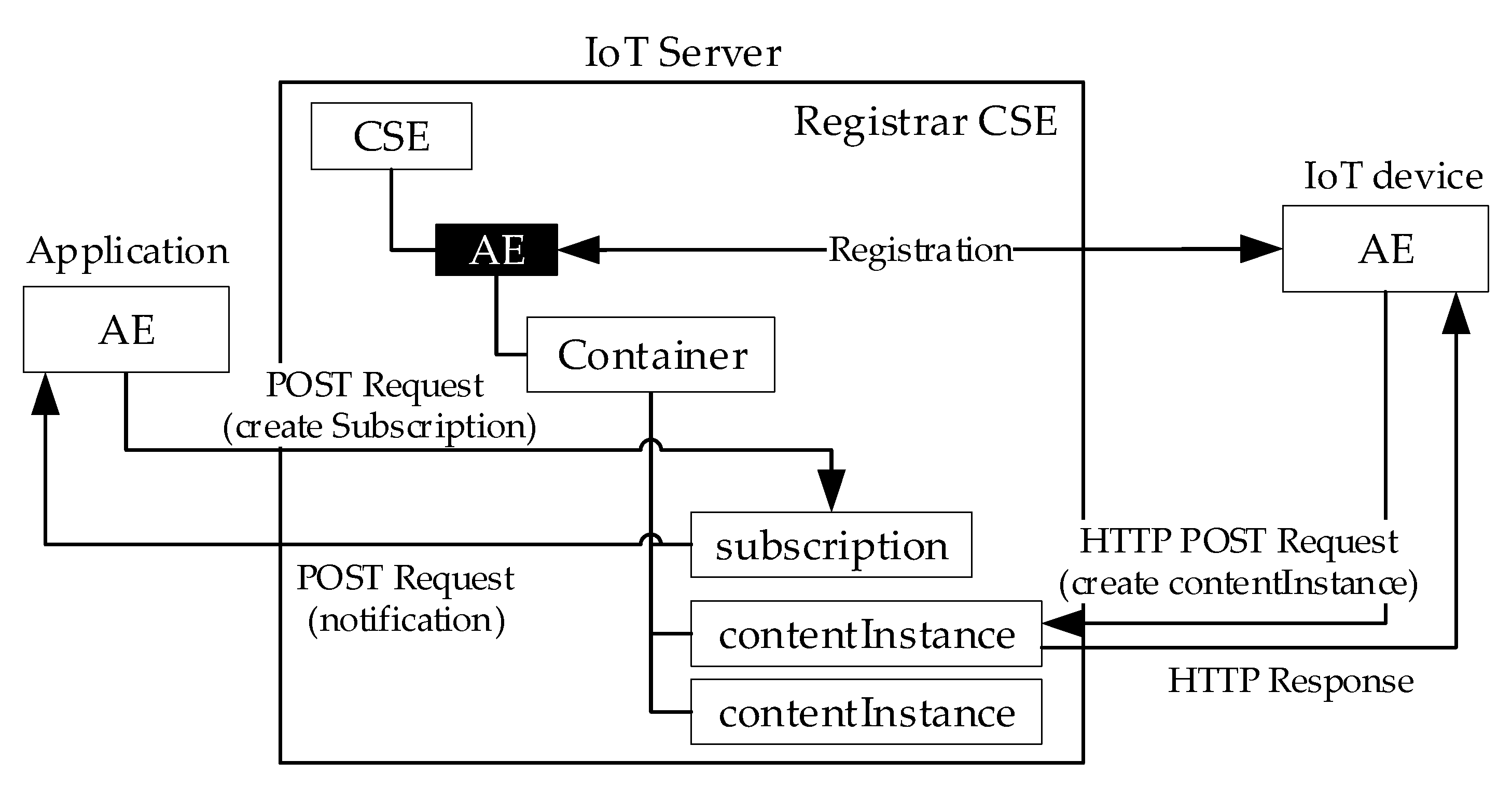
Figure 7.
Interworking Proxy application Entity (IPE) and relevant interfaces.

Figure 8.
Interoperability Solution between two domains by an Interworking Proxy.

Figure 9.
ResourceObjectType ObjectType mapping the basic structure of a oneM2M resource.

Figure 10.
OPC UA ObjectTypes modeling oneM2M resource types.

Figure 11.
Example of mapping a <container> resource, shown by (a), into the set of OPC UA Nodes shown by (b).
Figure 11.
Example of mapping a <container> resource, shown by (a), into the set of OPC UA Nodes shown by (b).

Figure 12.
OPCUA-IPE architecture.

Figure 13.
Example of Pre-provisioning method operated by the OPCUA-IPE.

Figure 14.
Procedure inside the OPCUA-IPE when a notification message is received from the Registrar CSE.
Figure 14.
Procedure inside the OPCUA-IPE when a notification message is received from the Registrar CSE.

Figure 15.
Interworking procedure inside the OPCUA-IPE when a Write service is invoked by an OPC UA Client.
Figure 15.
Interworking procedure inside the OPCUA-IPE when a Write service is invoked by an OPC UA Client.

Figure 16.
Scenario considered in the case study.

Figure 17.
Server CSE resource tree.
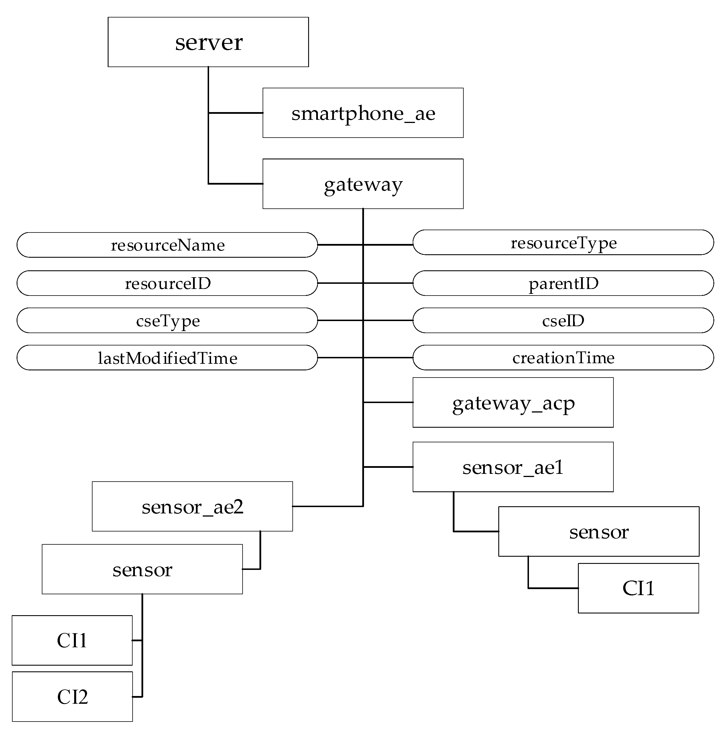
Figure 18.
OPC UA Nodes mapping the Gateway CSE resource tree.
Publisher’s Note: MDPI stays neutral with regard to jurisdictional claims in published maps and institutional affiliations. |
© 2021 by the author. Licensee MDPI, Basel, Switzerland. This article is an open access article distributed under the terms and conditions of the Creative Commons Attribution (CC BY) license (https://creativecommons.org/licenses/by/4.0/).
Share and Cite
MDPI and ACS Style
Cavalieri, S. A Proposal to Improve Interoperability in the Industry 4.0 Based on the Open Platform Communications Unified Architecture Standard. Computers 2021, 10, 70. https://0-doi-org.brum.beds.ac.uk/10.3390/computers10060070
AMA Style
Cavalieri S. A Proposal to Improve Interoperability in the Industry 4.0 Based on the Open Platform Communications Unified Architecture Standard. Computers. 2021; 10(6):70. https://0-doi-org.brum.beds.ac.uk/10.3390/computers10060070
Chicago/Turabian StyleCavalieri, Salvatore. 2021. "A Proposal to Improve Interoperability in the Industry 4.0 Based on the Open Platform Communications Unified Architecture Standard" Computers 10, no. 6: 70. https://0-doi-org.brum.beds.ac.uk/10.3390/computers10060070
Note that from the first issue of 2016, this journal uses article numbers instead of page numbers. See further details here.