
Product Lifecycle Management with the Asset Administration Shell


Department Production Engineering and Wood Technology, OWL University of Applied Sciences and Arts, Campusallee 12, 32657 Lemgo, Germany
*
Author to whom correspondence should be addressed.
Computers 2021, 10(7), 84; https://0-doi-org.brum.beds.ac.uk/10.3390/computers10070084
Submission received: 23 April 2021
/
Revised: 11 June 2021
/
Accepted: 16 June 2021
/
Published: 23 June 2021
(This article belongs to the Special Issue System-Integrated Intelligence and Intelligent Systems 2020)
Abstract
:Product lifecycle management (PLM) as a holistic process encompasses the idea generation for a product, its conception, and its production, as well as its operating phase. Numerous tools and data models are used throughout this process. In recent years, industry and academia have developed integration concepts to realize efficient PLM across all domains and phases. However, the solutions available in practice need specific interfaces and tend to be vendor dependent. The Asset Administration Shell (AAS) aims to be a standardized digital representation of an asset (e.g., a product). In accordance with its objective, it has the potential to integrate all data generated during the PLM process into one data model and to provide a universally valid interface for all PLM phases. However, to date, there is no holistic concept that demonstrates this potential. The goal of this research work is to develop and validate such an AAS-based concept. This article demonstrates the application of the AAS in an order-controlled production process, including the semi-automatic generation of PLM-related AAS data. Furthermore, it discusses the potential of the AAS as a standard interface providing a smooth data integration throughout the PLM process.
1. Introduction
Products and systems are becoming increasingly digitized. Most people are aware of examples from the consumer market, such as self-driving cars or smart homes. However, many industrial products that have been equipped with software in recent years are also part of this trend, for example, power supplies or connectors. The holistic organization of the product lifecycle of these products and systems based on methodical and organizational measures using IT systems is called product lifecycle management (PLM). PLM is a significant enhancement of the concept of product data management (PDM), which includes the organization of CAD drawings; the management of product data, such as the bill of materials (BOM); and the application of corresponding project management processes [1].
In practice, numerous PLM tools have become established. However, none of these tools manage all product information or, in operational practice, several systems are used, such as CAD systems and simulation systems [2]. This heterogeneity of the IT landscape makes a continuous data chain in product lifecycle management difficult, since the implementation of such data chain between the different IT systems requires a lot of effort. Although there are standards for a subset of the data, such as STEP or JT, the outlined situation still poses challenges to companies, including the following, according to [3]:
- Due to individual item naming in the systems, different interpretations of an artefact occur within companies.
- Different data formats are used for the same processes.
- Data should be accessible in such a way that it can also be used in areas for which it was not intended when it was created. This also includes independence from the location as well as from the company.
- The completeness of data cannot be guaranteed because it is often stored in different data repositories or even exists as documents in digital or paper form.
- Data access is hindered by data security requirements.
- Effort is needed to make the data of one PLM system accessible to other systems.
In addition to these points, the PLM processes of digitized products face another challenge: traditional PLM systems are not designed to manage the creation of the software of digitized products and systems. Therefore, software engineers have developed so-called application lifecycle management (ALM) processes and tools in parallel to the PLM concept. The goal of ALM is to provide a comprehensive technical solution for monitoring, controlling, and managing software development throughout the application lifecycle [4].
Since digitized products and systems require PLM and ALM to work together, many activities and discussions in research and industry are currently actively targeting smooth PLM/ALM integration [5,6,7]. For example, the authors were members of a research team that developed use cases for PLM/ALM integration in an industrial case study [8]. However, solutions such as those described above involve PLM/ALM solutions from only one vendor. Although the Open Services for Lifecycle Collaboration (OSLC) standard [9] was used in the case study, the solution remained vendor specific. However, the engineering and production of digitized products require PLM/ALM integration between tools from different vendors. Today, to achieve this goal, custom interfaces are required (e.g., [10]).
In addition, the emergence of the Digital Twin concept makes the smooth integration of data and tools throughout the PLM phases, including the production process, even more necessary. There are a variety of definitions of Digital Twin that differ in scope and level of detail [11]. However, the opinion that the data of the Digital Twin should be merged in an automated way across all PLM phases is consolidating [12].
To address these challenges, this work proposes an approach based on the Asset Administration Shell (AAS). The result is a concept in which the data generated during the engineering and production of a digitized product or system is managed in the AAS. This makes the data available to all PLM phases in a standardized manner. A particular focus of this work is the integration of ALM data into the PLM process.
This article is structured as follows: Section 2 explains the concept of the AAS and other relevant background information. Section 3 outlines the major research goals and the research method. Section 4 describes the concept for using the AAS in the engineering process. Section 5 extends the AAS-based data integration to the production process, reusing data of the engineering process. Section 6 discusses the achievement of the major research goals and the success factors of the AAS-based strategy. The article concludes with suggestions for further research topics and a final discussion.
2. Related Background
2.1. PLM and Systems Engineering
PLM is a comprehensive term, which generates numerous opinions. According to [1], it is “the business activity of managing, in the most effective way, a company’s products all the way across their lifecycles; from the very first idea for a product all the way through until it is retired and disposed of”. The overall objective is to increase revenue by reducing product-related costs and lead-times.
PLM is related to the research field of systems engineering. There are many definitions of systems engineering. However, it is generally considered as an interdisciplinary approach that enables the successful implementation of systems [13]. It is obvious that the product lifecycle management of digitized products and systems also involves multiple disciplines or domains. A difference between these terms can be seen in terms of the importance of IT tools: systems engineering is rather a set of methods that are independent of concrete IT tools, while PLM includes a strong focus on IT tools. Nevertheless, any activity aiming for improved, standardized data integration throughout the PLM process contributes to systems engineering research.
2.2. Digital Twin
The Digital Twin is seen as a major tool for increasing the productivity in PLM processes in the age of industrial digitalization. Therefore, a number of publications are focusing on this concept, creating several definitions of the term [11]. However, these are not always of value in the practical implementation of Digital Twins in PLM processes. Although contradictory definitions do not hinder an investigation of the development of Digital Twins in PLM processes, the authors presented an alternative approach to deal with Digital Twins. The so-called Digital Twin theory was proposed during the work on the TeDZ project (see section “funding”). Therefore, it is only briefly explained here. Despite this focused view, the reader should be aware that a tremendous amount of research on Digital Twins has been conducted in recent years and continues to be carried out.
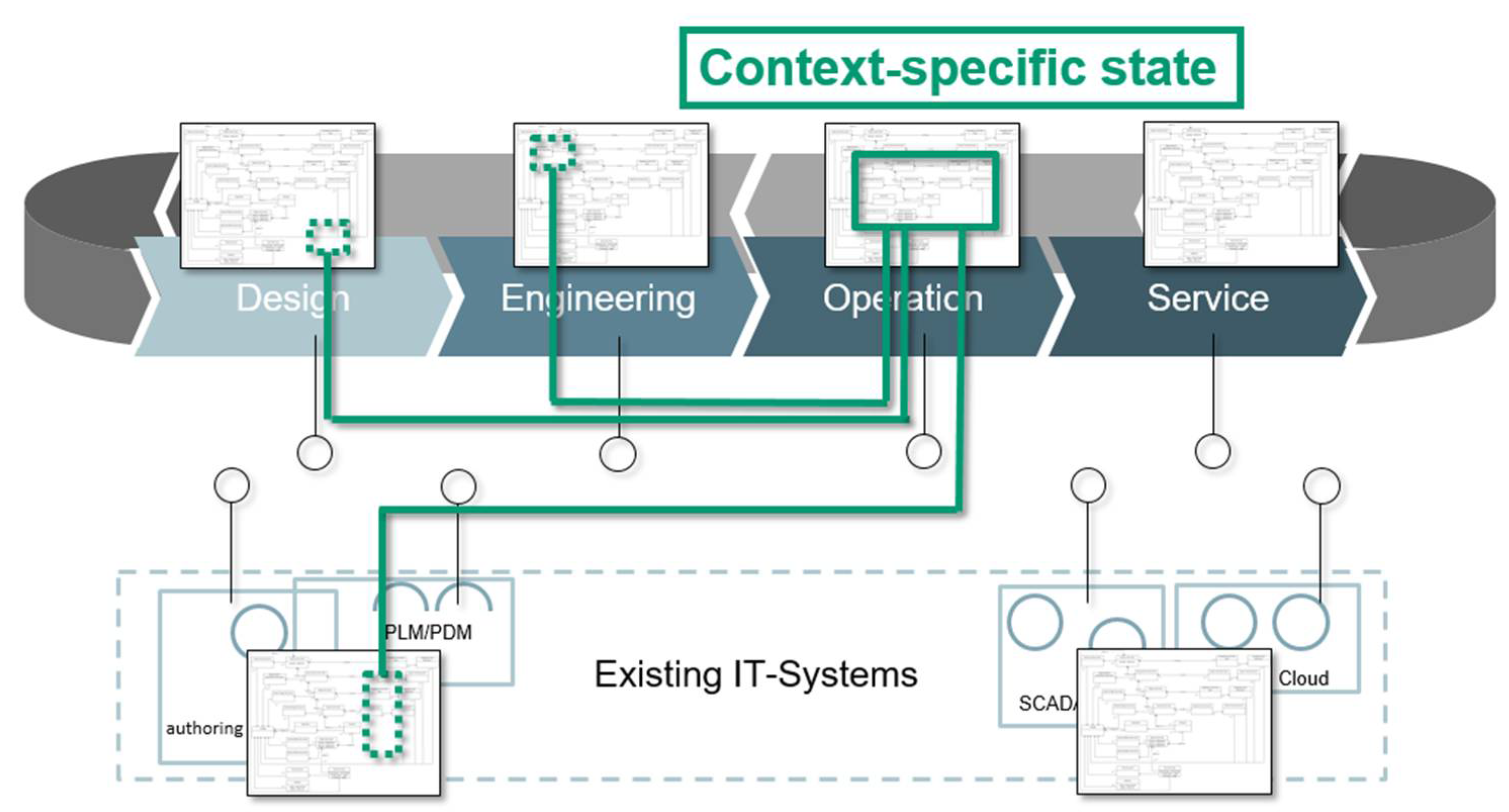
Digital Twin theory assumes that throughout the PLM process there are multiple stakeholders with different perspectives on the digital representation of products and systems who are working with this digital representation at the same time. These assumptions form the basis of several hypotheses of a Digital Twin, namely [14]:
- A Digital Twin is a digital representation of an asset.
- A Digital Twin is located in several places simultaneously.
- A Digital Twin has multiple states.
- The Digital Twin has a context-specific state in a specific interaction situation.
- The information model for Digital Twins is infinitely large. It is called the real information model.
- The real information model can be finitely approximated for a specific application scenario, becoming a rational information model.
- The rational information model cannot be stored in a single place.
- The rational information model is never completely visible.
For an explanation of these hypotheses, the reader is referred to the original article. However, Figure 1 shows some of the elements named in the hypotheses and their relation to the PLM process.
2.3. Asset Administration Shell (AAS)
Digital Twin theory is a theoretical concept. It does not indicate any guidelines for creating Digital Twins. A central technology implementing Digital Twins can be seen in the Asset Administration Shell (AAS). However, there are many other technologies available implementing Digital Twins.
The “Plattform Industrie 4.0”, a German consortium of politics, companies, and research organizations, introduced and specified the concept of the AAS [15]. In order to promote this concept, the Industrial Digital Twin Association (IDTA) was recently founded. The AAS is a standardized digital representation of an asset. An asset is anything of value and can be a physical or logical object (e.g., a product or a service). The AAS contains digital models of various aspects of the asset in the form of submodels and describes the asset’s technical functionality by displaying it via a standardized interface.
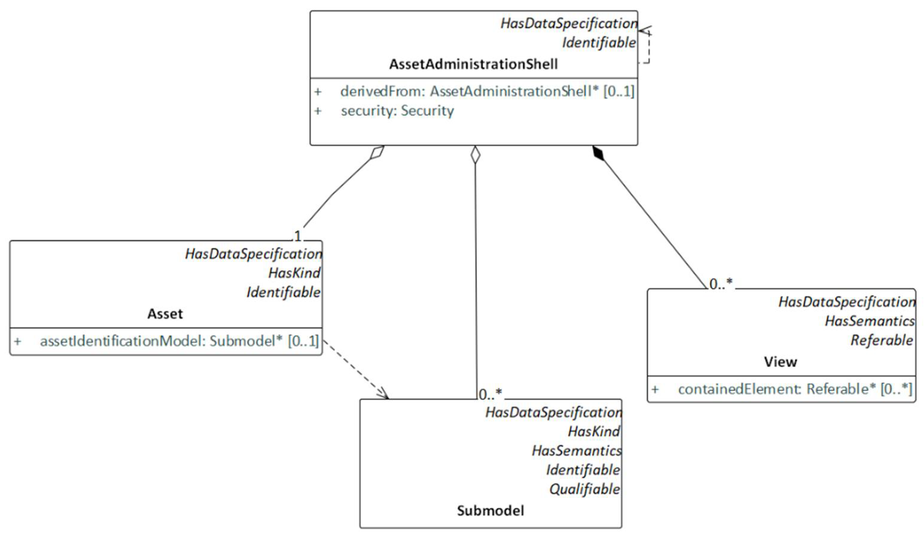
The AAS data model consists of three main classes: the asset class, the submodel class, and the view class (see Figure 2). The asset class provides information on the kind of asset (type or instance) and the asset identification submodel. The submodel class refers to a well-defined domain or subject matter (e.g., the asset identification and drive parameters). Submodels can be considered the main information store of an AAS, as they provide the central data on an asset. There is no limit to the number of submodel classes. When developing an AAS of an asset, any new submodel can be defined. This research work used submodel classes to model PLM data, such as the bill of materials (BOM).
The view class provides a projection of the AAS model seen from a particular perspective, omitting entities that are not relevant to that perspective.
In addition to these main classes, the AAS data model defines many more classes, providing detailed information about the asset (e.g., data type classes). Furthermore, the AAS specification defines the representation of the AAS data model in standard data interchange formats, such as Extensible Markup Language (XML) and JavaScript Object Notation (JSON).
The AAS specification does not define how to implement an AAS. However, in order to provide standardized implementations of the AAS from different vendors, several initiatives are currently active, including the AASX Package Explorer. This is an open-source software tool enabling a user to create, edit, and view an AAS [16]. Furthermore, it provides access to the AAS via an Open Platform Communications Unified Architecture (OPC UA) or Message Queuing Telemetry Transport (MQTT) interface. This work used the AASX Package Explorer to demonstrate the submodels created for the purpose of the research. The second initiative to mention is the BaSys 4.0-Middleware, which provides an open-source platform called BaSyx, supporting the implementation of a vendor-specific AAS [17,18].
In order to provide PLM data in an AAS submodel structure, there must be the corresponding data models. However, the “Plattform Industrie 4.0” has defined only a few such AAS data models (e.g., digital nameplate). As none of these fit the purpose of this work, which focused on a general strategy to enable data integration throughout the PLM process with the AAS and not on the data models themselves, existing data models outside the AAS specification were used. They are explained in the next section.
2.4. Selected Data Models in PLM Processes
There is no standardized all-encompassing PLM data model. However, there are phase-specific and domain-specific standards, respectively. For example, Siemens, a market leader in the area of PLM software, defined the PLM XML schema [19]. It is a Siemens internal data model of its PLM tool Teamcenter to exchange data between two Teamcenter instances using XML files. Furthermore, it supports application integration through workflows. PLM XML is a very comprehensive model. However, it is a proprietary format, and there is no widespread acceptance in practice.
Another example is derived from the ALM domain: there is no standardized data model for ALM. However, as requirements engineering is an important task in ALM, there is a so-called Requirements Interchange Format (ReqIF) [20], enabling the exchange of requirements between different tools. Similarly to PLM XML, ReqIF enables data exchange between IT tools using XML. ReqIF originated in the automotive industry. However, since its standardization by the Object Management Group (OMG), it has also been applied in other industries and fields. ReqIF covers requirements as well as the documents containing these requirements. Furthermore, as requirements are normally written in natural language, ReqIF is not limited to requirements but also supports other artefacts. For example, this work uses ReqIF to exchange assembly instruction data containing text and pictures.
2.5. OSLC-Based Data Integration
When discussing the exchange of data throughout a product lifecycle, one cannot neglect to mention the OSLC standard [9]. OSLC is designed to connect data and to create a digital thread across domains, applications, and organizations. It uses the concept known as the Resource Description Framework (RDF) for data exchange between different applications. In order to enable OSLC-based data exchange, the tools involved must provide an appropriate interface. In theory, data exchange between OSLC consumers and OSLC providers is tool independent. However, in reality, tool integration can contain vendor-specific elements, meaning that only tools from a single vendor fit together optimally. Furthermore, the OSLC standard is not designed to facilitate anything other than data access between tools. For example, operational data (e.g., device temperature) from an asset are not part of the OSLC design concept.
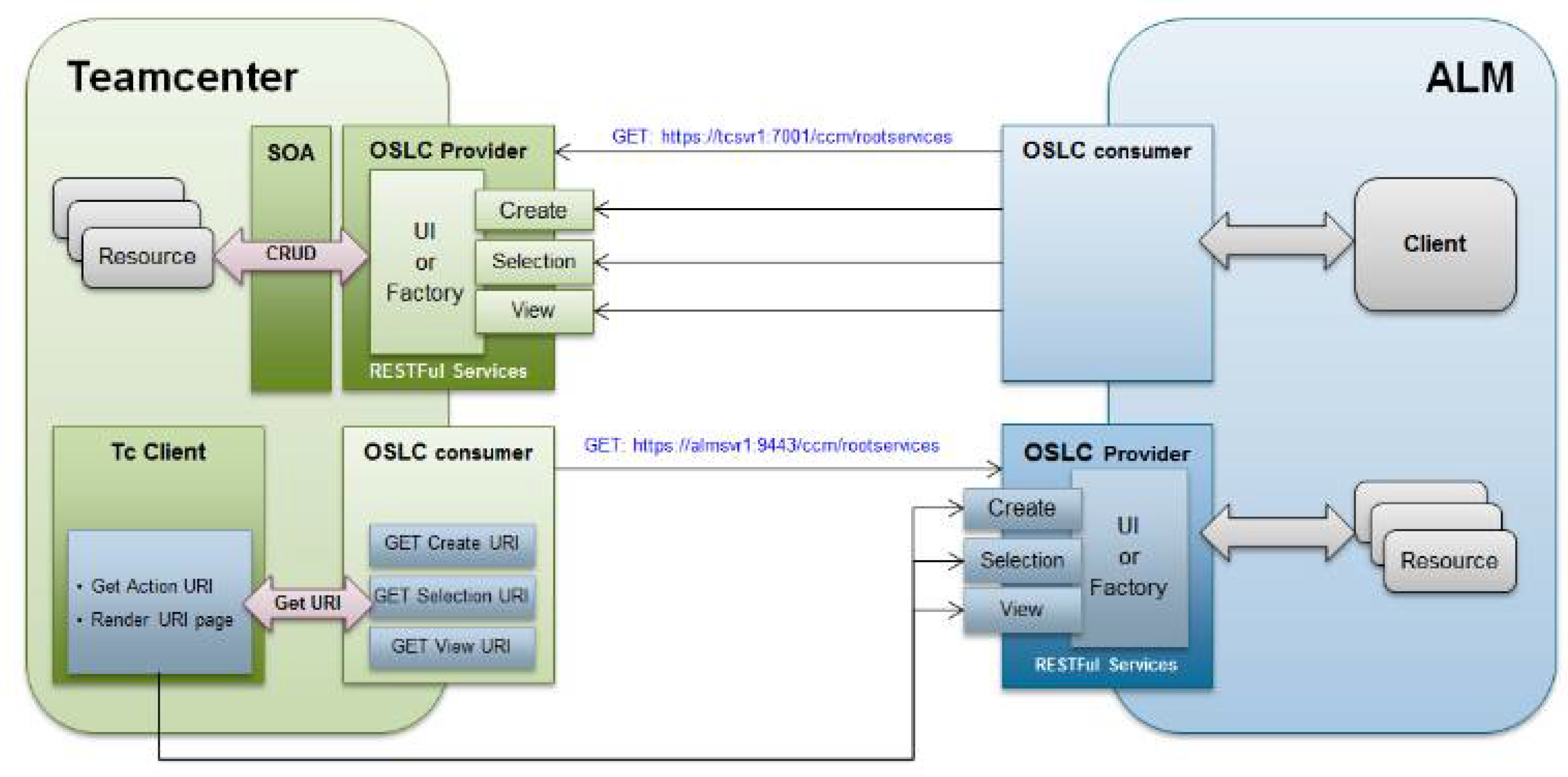
Although there is no all-encompassing PLM data model, tool vendors offer proprietary solutions for PLM data integration throughout the PLM process, as shown in the following example: As previously mentioned, the authors have already worked on concepts for PLM/ALM integration [6]. These activities made use of the Siemens toolchain with Teamcenter (PLM) and Polarion (ALM). Data exchange between these tools is based on the OSLC standard (see Figure 3). In addition to various use cases from the industry, the research team created several other use cases for the so-called “SmartLight”, which is a simple mechatronic product involving the mechanical, electronic, and software domains (depicted in Figure 6). Among the use cases under investigation was the assignment of a requirement, managed in ALM, with a design element storing CAD data. Although these CAD data are managed in Teamcenter, they can only be edited in the CAD tool Siemens NX. The data integration between NX and Teamcenter is based on an internal Siemens interface.
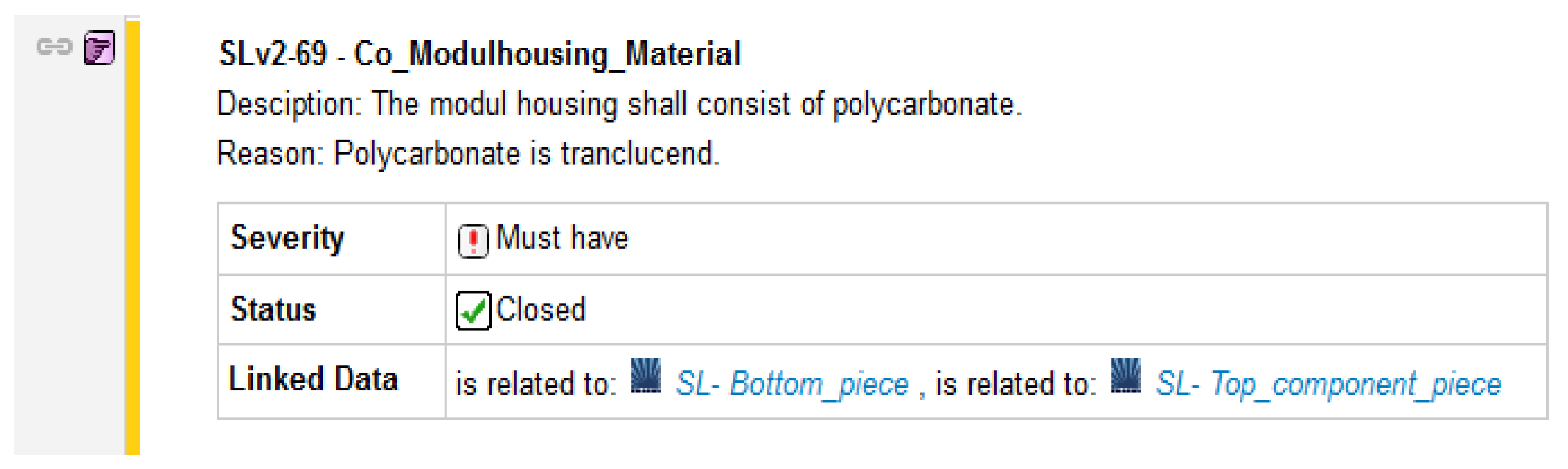
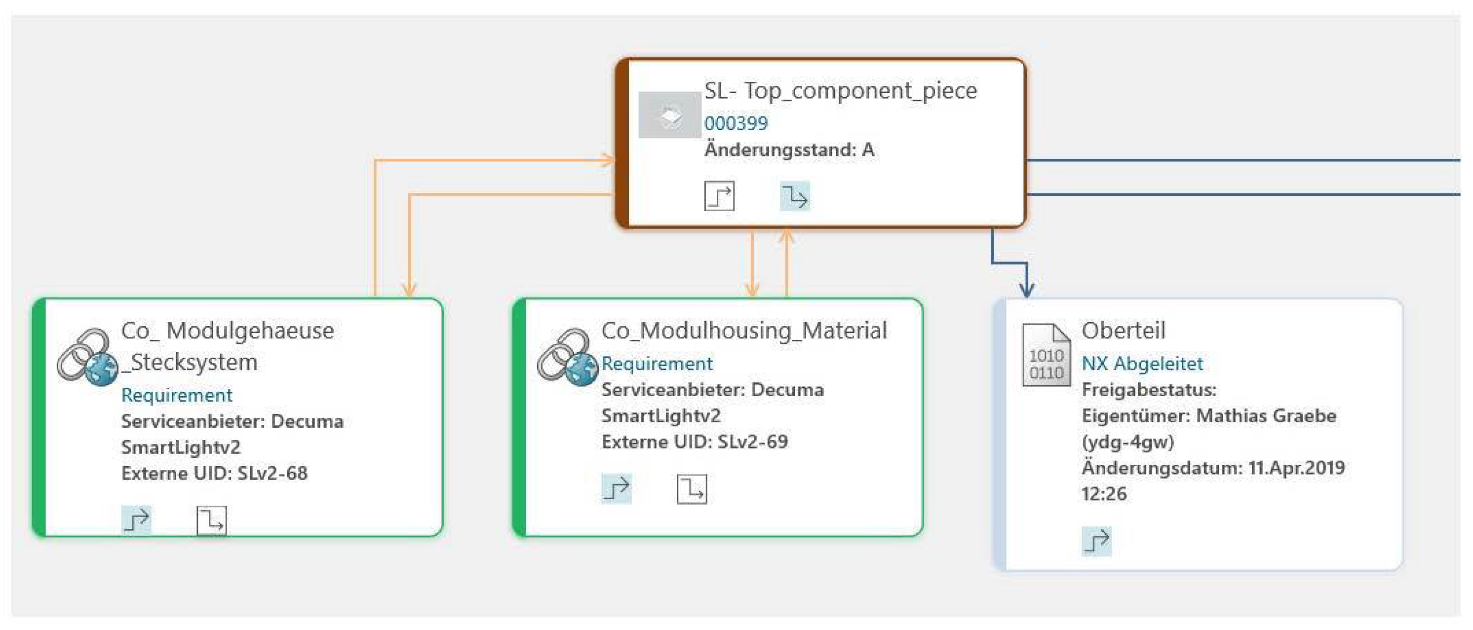
Figure 4 shows an actual view of the Polarion user interface as an example of the PLM/ALM interface. The requirement “SLv2-69 Co_Modulhousing_Material” (ALM) is linked to the design elements “SL-Bottom_piece” and “SL-Top_component_piece” (PLM).
To create such links, the Siemens toolchain provides specific dialogs. Furthermore, with the so-called “Delegated UI” technology, Teamcenter data can be edited in Polarion and vice versa. Such features are vendor specific and are not covered by the OSLC specification. Therefore, the authors perceive an increasing need for vendor-independent approaches to linking such data.
3. Major Research Goals and Research Method
This research work addresses product lifecycle management in the sense of Industry 4.0. As there are many aspects of Industry 4.0, the research team set itself the task of focusing on the application scenarios defined in [21], namely:
- OCP—Order-Controlled Production;
- AF—Adaptable Factory;
- SAL—Self-organizing Adaptive Logistics;
- VBS—Value-based Service;
- TAP—Transparency and Adaptability of Delivered Products;
- OSP—Operator Support in Production;
- SP2—Smart Product development for Smart Production;
- IPD—Innovative Product Development.
Industrial experts and renowned researchers have identified these application scenarios as enhancements of the current state of the art. Therefore, the intention of this work is to create results that allow their implementation in practice. When discussing the project results in Section 6, descriptions of these application scenarios are given.
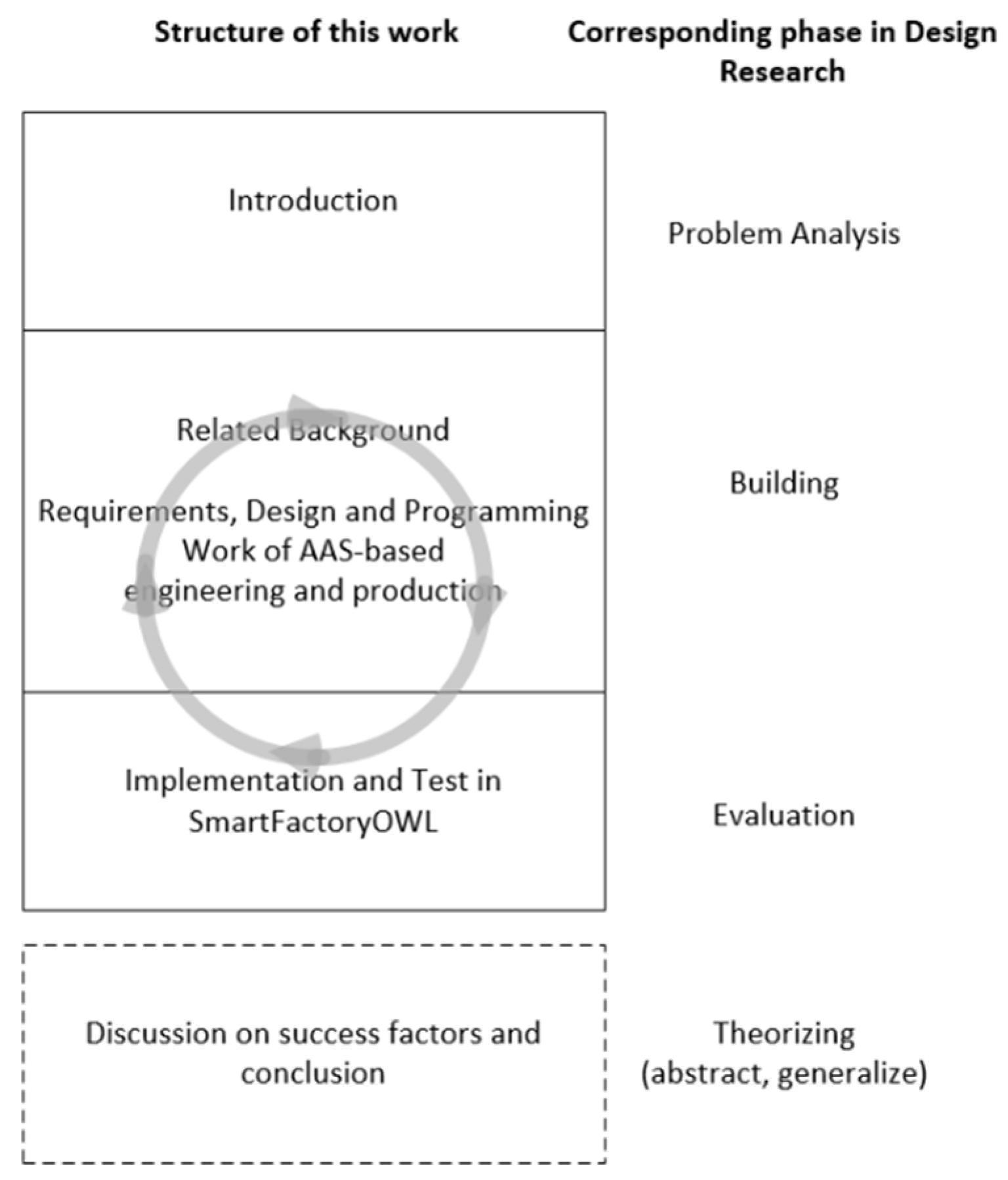
This research work is divided into the creation of the conceptual basis to solve the problem, a practical implementation evaluation, and a theory building. It is based on the methodological approach of Design Research (DR). DR analyses the application of designed IT artefacts to understand, explain, and improve information systems. As there are several definitions of DR, this work follows the explanations in [22]. DR consists of two activities: the design of one or more IT artefacts and theory building. The IT artefacts (in this work, these are the several AASs) and their contribution to an overall solution have a local practical reference to the SmartLight, which is designed and produced in a research and test factory. The local results obtained in the design of the IT artefacts are used to feed the theorizing with the aim of forming generally applicable results from them. As this research work is ongoing, the theorizing process is also ongoing.
The design of an IT artefact consists of the following phases: problem analysis, building, and evaluation. The building and evaluation phases can be repeated several times, which was conducted in this work. Figure 5 shows the steps of the methodological approach and their assignment to the DR phases.
4. AAS-Based Engineering Process
One focus of this work lies in the engineering process, especially in the PLM/ALM integration. This section explains why and how the AAS is utilized in this context.
4.1. Requirements
When aiming to create a vendor-independent standardized concept of PLM/ALM integration, the requirements for such a concept must be defined. The major requirements identified by the research team are as follows:
- R1: The concept must be based on a standard in order to enable vendor-independent integration.
- R2: The underlying data model must provide comprehensive access to all data created for or by an asset in order to include data other than PLM/ALM data.
As well as these high-level requirements, the concept should fulfil specific requirements for PLM/ALM integration. However, these requirements are often user specific. In order to discuss the validity of the concept described in this article, several requirements developed in the industrial case study described in [8] were adopted as references. Given that Teamcenter is the PLM tool and Polarion is the ALM tool, the following requirements must be fulfilled:
- R3: It must be possible to link a Polarion work item with a Teamcenter item and vice versa.
- R4: It must be possible to link a Teamcenter item with a Polarion document.
- R5: It must be possible to access the data of any attribute of a Polarion work item from the linked Teamcenter item and vice versa.
- R6: It must be possible to link more than one Polarion work item with one Teamcenter item in a single action.
- R7: When creating a traceability report in Polarion, all linked Teamcenter items must be included and vice versa.
- R8: The status of a Polarion work item can only be changed if the status of the linked Teamcenter item has a dedicated status.
Further requirements are described in [8]. However, they are highly specific to the industrial case study. As this work aims to provide a new general strategy for data integration in a PLM process, such specific requirements must be validated in the future.
4.2. Design and Implementation
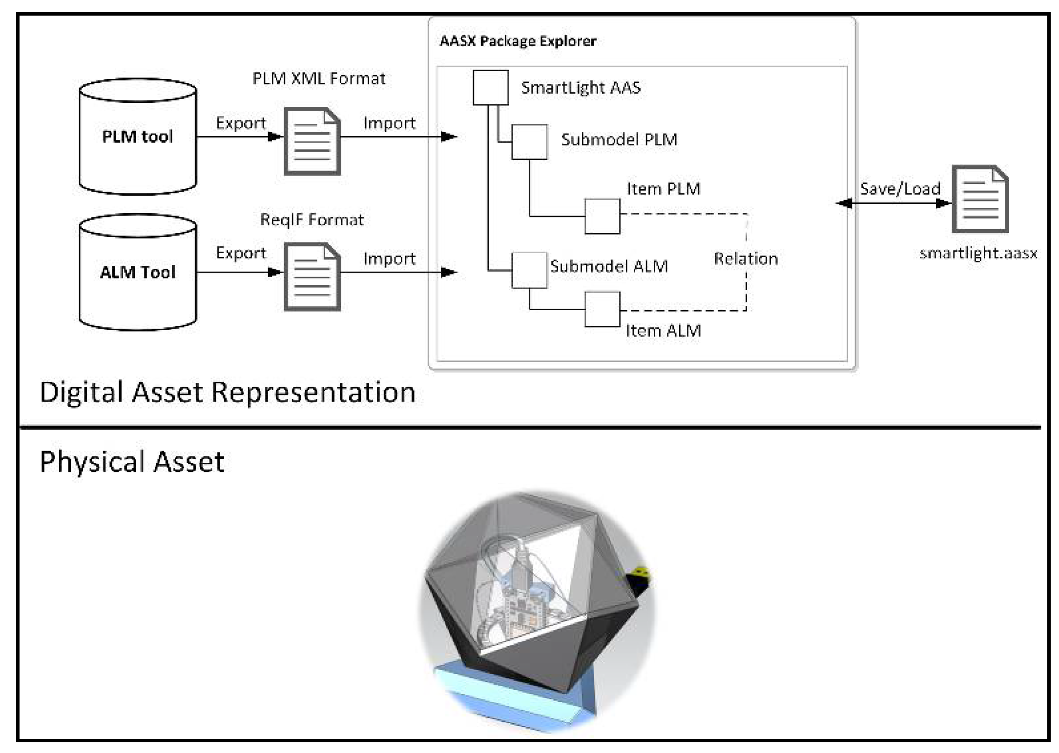
Figure 6 shows the general design concept for providing PLM/ALM data to an AAS data model, which is explained using SmartLight.
The PLM data were exported from the PLM tool using the PLM XML data format. The same was carried out for the ALM data using the ReqIF data format. Both sets of information were stored in separate XML files.
In the next step, the research team created an AAS for SmartLight using the AASX Package Explorer. To provide exported PLM/ALM data to the SmartLight AAS, the research team developed two so-called “importers”, enabling the importation of the data to the AASX Package Explorer. The PLM data were imported as a PLM submodel, while the ALM data were imported as an ALM submodel. After importing these data, elements of both submodels could be related to each other. For this, the AAS RelationshipElement class was used. This class contains the members first and second, which are known as referable elements.
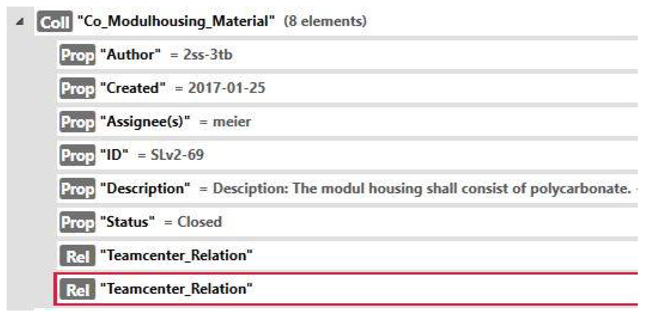
Figure 7 shows an example of an AAS-based PLM/ALM relation. For a better comparison, this is the same example as that described in Figure 4; namely, it demonstrates the properties of the SmartLight requirement “Co_Modulhousing_Material”, which is part of the requirements specification managed in the ALM tool. All the properties of this requirement were created during the ReqIF import.
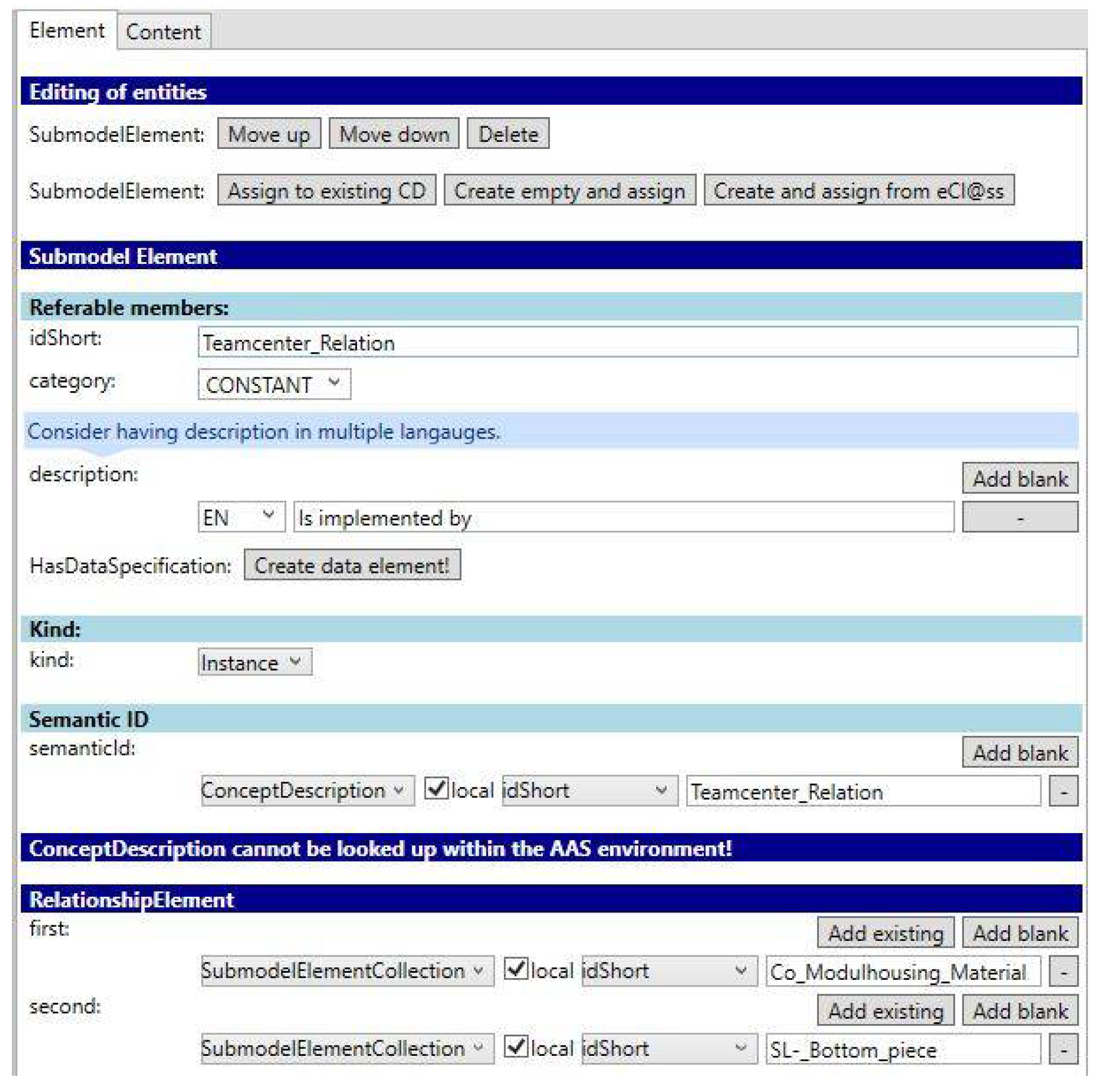
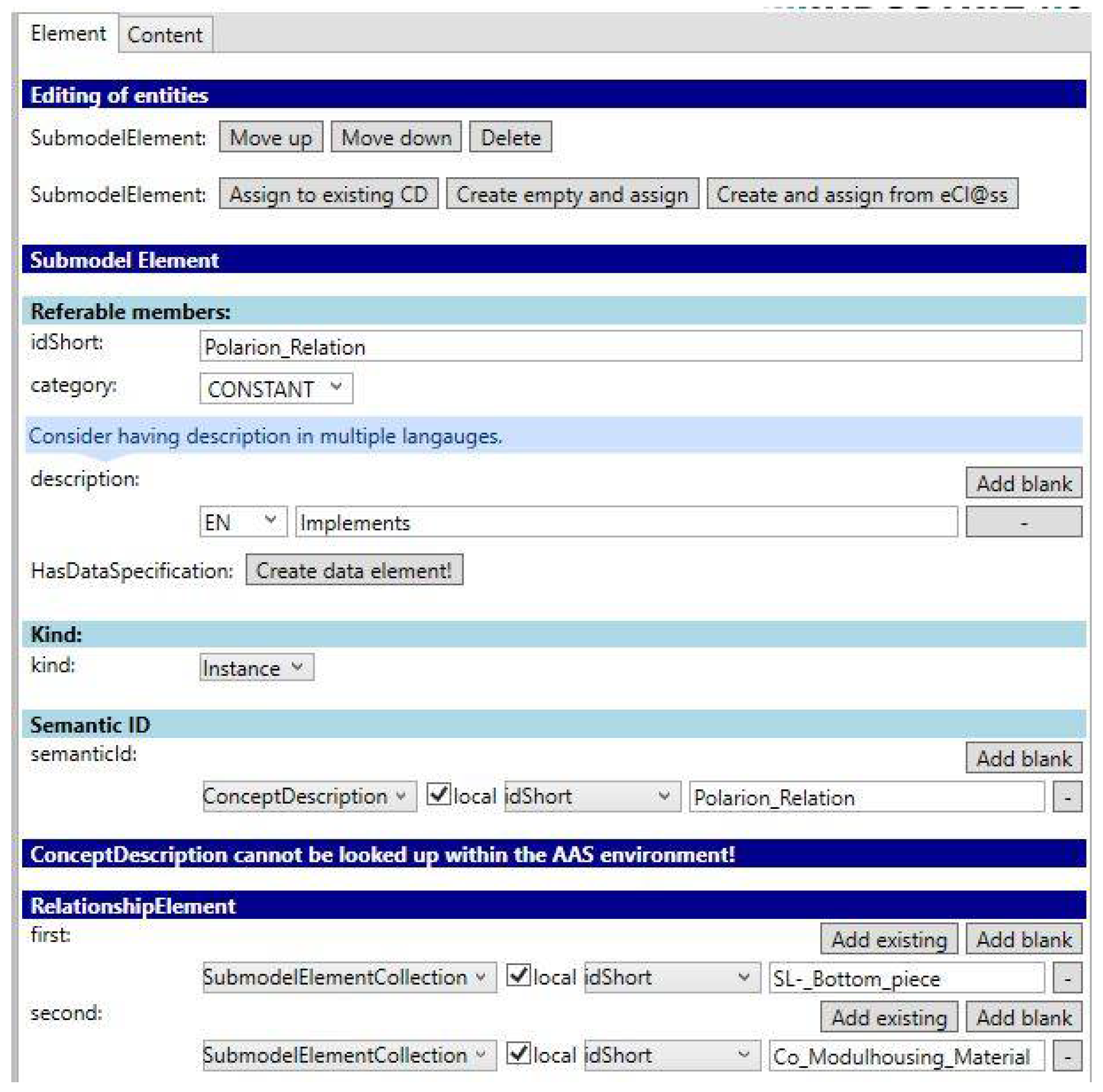
As shown in Figure 8, the requirement contains two instances of the RelationshipElement class. The first element is the requirement itself. The second element is the PLM data item “SL-Bottom_piece”. The semantics of this relation are part of the description and have the following meaning: the requirement “Co_Modulhousing_Material” is implemented by the design element “SL_Bottom_piece”.
The same relationship was also added to the PLM submodel element, which was imported by the PLM XML importer (see Figure 9). The differences to the instance of the RelationshipElement class, which is part of the ALM item, are that the first and second elements are swapped and the semantic meaning is changed. The relationship from the viewpoint of the PLM item has the following meaning: the design element “SL_Bottom_piece” implements the requirement “Co_Modulhousing_Material”. It can be seen that two instances of the RelationshipElement class for one relation are required, which may be considered an unnecessary double data entry. However, a RelationshipElement class describes the relation from the viewpoint of one item. For example, there is a significant difference between an “implements” relationship and an “implemented by” relationship. Therefore, as there are two viewpoints on one relation, two instances of the RelationshipElement class are needed.
This concept allows an AAS data model to be enriched with PLM/ALM data and means that relations between these data can be created. However, this strategy is just an initial starting point to enable PLM/ALM integration with an AAS. The following requirement validation explains this statement.
4.3. Requirements Validation
The concept fulfils the main requirement R1 (see Section 4.1). As previously mentioned, the AAS was developed by a number of companies and organizations. As it is designed to provide all digital data for an asset, R2 is also fulfilled. It has the potential to go well beyond the current most popular strategy for life cycle integration using OSLC.
The explanations in Section 4.2 demonstrate that the concept can fulfil requirement R3: links can be set between any submodel elements, including between elements that represent ALM requirements and PLM design revision items.
As the ReqIF standard allows exporting not only single requirements but also documents containing requirements, a document can be imported as a submodel element into an AAS. As a submodel element, it can be linked with any other element, including a PLM item. Therefore, requirement R4 is fulfilled.
A user can configure the item attributes (e.g., author and status), which should be included in a ReqIF or PLM XML export. Therefore, the properties of the imported submodel elements depend on the specific user configuration. Thus, requirement R5 is fulfilled.
Requirements R6, R7, and R8 cannot be validated without explanatory comments. The AAS data model does not prevent these requirements from being fulfilled. However, the implementation of these requirements depends on tool support. The AAS data model is simply the data storage of the information on an asset. The graphical views on this data model depend on the tools using the data model. This research work used the AASX Package Explorer to view the data. Although it provides basic editing functionality, it is not designed to be a tool for real-world scenarios. Therefore, to fulfil these requirements, the PLM/ALM tools should implement the corresponding functionalities. To illustrate a possible graphical user interface, Figure 10 shows a vendor-specific implementation of requirement R7. This is the same example as that in Figure 4 and shows trace links between Teamcenter and Polarion.
5. AAS-Based Production Infrastructure
After the presentation of how the AAS can be used in engineering processes, this section discusses the potential role of the AAS in future production environments. In the TeDZ research project (see section “funding”), infrastructure for order-controlled production of the aforementioned SmartLight based on the AAS was designed and implemented. The associated production facilities are located in the SmartFactoryOWL, which is an Industry 4.0 research and test factory jointly operated by the Fraunhofer Application Centre IOSB-INA and the OWL University of Applied Sciences and Arts in Lemgo, Germany.
5.1. Requirements of the AAS-Based Production Infrastructure
First, an overview of the identified requirements for a working environment for an AAS-based production infrastructure is given. These requirements relate to a scenario in which a customer orders a specific variant of SmartLight and in which the production facility autonomously selects an appropriate assembly workstation. In order to gain an improved understanding of the requirements, the following aspects must be considered: The project team agreed that the AAS could be seen as a synonym for the Digital Twin, because the AAS meets many characteristics of the Digital Twin. In particular, it is a useful means to prove the hypotheses of Digital Twin theory (see Section 2.2). The project team identified the following requirements:
- R10 (automatic creation of a Digital Twin): during the ordering process, an instance AAS must be created automatically based on a template.
- R11 (extend/change a Digital Twin): since a server hosts the AAS and communication protocols are implemented, the AAS must be changed and/or extended.
- R12 (versioning a Digital Twin): two different types of the same product must be created to demonstrate how to manage the production of different products.
- R13 (views on the AAS): to protect certain information, types and instances must be implemented. Instance information shows only selected information of that type.
- R14 (production based on AAS data): the manufacturing process must use instance and type data when producing an asset.
- R15 (automatic production data): the production process manufacturing information must be entered to create the “Digital Nameplate” (see Section 2.3).
These requirements served as input of the design and implementation of the AAS-based production infrastructure.
5.2. Design and Implementation
In order to understand the implementation of the production infrastructure and the above requirements, the AAS model is explained in more detail. Regarding the AAS specification [15], the step in order to follow the meta-model description is to separate the information models into types and instances, as displayed in Figure 11. This separation is important for manufacturing companies, since they aim to protect certain information from going public and must manage different versions of the product they produce. Therefore, types contain all information from the engineering phase (e.g., the ALM data), including proprietary data and files, whereas instances contain the data that are only related to one specific instance of an asset (e.g., the production data and operation data). This information is needed by companies that use the product but do not manufacture it. Since the information provided by the types may be useful to the instance owner, a link to the type is provided by each instance using the derivedFrom property, which is part of each AAS. To secure proprietary data, the outside access via this link, types can be modified to provide only public data. More information for the separation of data into types and instances can be found in [15] (p. 29).
The overall production and engineering infrastructure of SmartLight created in this work contain the following elements:
- PLM/ALM data and tools
- To create the engineering data of the product (see Section 4).
- Ordering System
- To trigger the production of the asset by creating the instance(s).
- Production System
- System to produce the asset.
- Several AAS
- To store production, engineering, and operation data.
- AAS Registry
- Provides addresses for all AASs involved in the production.
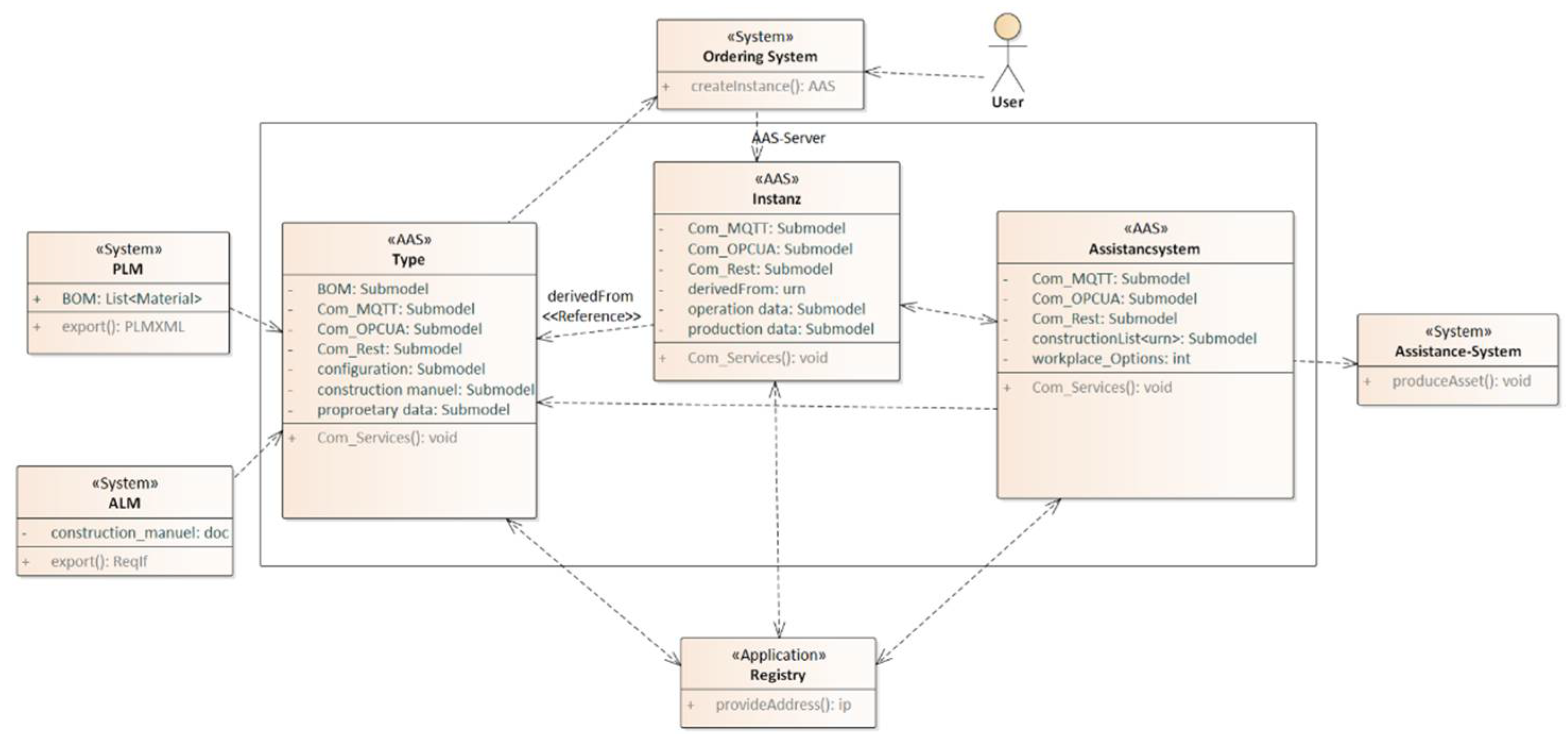
The bill of materials (BOM) is provided by the PLM system as part of the PLM XML data. Furthermore, the ALM system is used to store the instructions for the manual assembly of SmartLight (step-by-step instructions including pictures). These data are imported into an AAS type and are linked by the already explained Relationship Elements (see Section 4). Moreover, the type AAS will be provided with a configuration submodel. This submodel can offer, for example, different colours. To facilitate communication, all AAS are equipped with submodels that provide the fundamental properties to communicate using OPC UA, REST, and MQTT. Moreover, a so-called AAS registry application is added that can redirect communication by providing server addresses to all AASs based on their unique identifier.
To complete the infrastructure, an additional AAS is added to represent the production system. This AAS contains a list of addresses to the AAS instances of SmartLight that can be manufactured using the corresponding production system. Figure 12 shows the infrastructure model.
The dynamic processes in this infrastructure are as follows: First, PLM and ALM data are provided to the AAS type(s), where they are used by an ordering system to generate orderable objects. Second, the configuration submodel is added, describing additional product options that can be selected in the shop.
If the customer chooses a configuration and orders a product, the ordering system triggers a process creating a product instance. Furthermore, it adds certain properties into submodels to control the production of the product. In this process, the instance AAS can communicate with other AASs using their accompanying services. For example, an instance can communicate with the production system to register as a product that has to be manufactured. Whether the manufacturing process is possible or not is decided autonomously by comparing the production requirements with the workstation options. The corresponding production requirements are based on the data imported from the PLM system. If the result of this “dialog” is positive, the address of the instance AAS is added to a production queue within the production system AAS.
By determining the address of a product instance, the AAS of the production system can access type data by following the “Instance-Type” connection variable in the derivedFrom property. In this way, it accesses the product’s assembly instructions and can display them at the workstation to assist workers with manual assembly. Moreover, the instance connection allows the production system to write production-related data into the instance, for example, a digital nameplate, a user manual, or general production data. After production is finished, the product and the AAS instance can be delivered to the customer.
The video mentioned in the Supplementary Materials section demonstrates the AAS-based order-controlled production process implemented in the SmartFactoryOWL.
5.3. Requirements Validation
The usage of an AAS-based infrastructure provides a unique opportunity for companies to obtain a standardized digital interface to access any asset during a product lifecycle. Although the described infrastructure is a simplified example of production infrastructure in a research facility, it has the potential to serve as a template for real production environments. The following evaluation of the requirements described in Section 5.1 indicates that this statement is justified:
- R10 (automatic creation of a Digital Twin): the AAS is automatically created by the ordering system when a customer orders a product.
- R11 (extend/change a Digital Twin): several AASs are integrated into the system. By exchanging data, they mutually modify their data models. Additional information can be added to a specific AAS at any time.
- R12 (versioning a Digital Twin): it is possible to order different configurations of the same product. For each of these configurations, the production infrastructure creates a separate AAS instance representing a specific product configuration.
- R13 (views on the AAS): Data access to the AAS type is restricted or can be controlled. This ensures the protection of sensitive product-type data.
- R14 (production based on AAS data): as shown in Figure 11, the production infrastructure significantly uses the concept of the AAS, which is a major goal in this work.
- R15 (automatic production data): The AAS of the assembly station enters production data into the AAS instance of the product. In this way, it enriches the information model delivered to the customer.
However, this is an initial assessment for a limited example. For a more in-depth analysis, the example should be made more complex, and more requirements are needed.
6. Overall Evaluation and Solution Success Factors
6.1. Evaluation of Industry 4.0 Application Scenarios
As stated in Section 3, a major goal of this work was to find ways to implement the Industry 4.0 application scenarios given in [22], which follows a discussion on the achievement of this target.
OCP—Order-Controlled Production:
- Description [22]: “This application scenario revolves around orders and describes how to dynamically organize the production resources required for the order”.
- Evaluation: The OCP is among the main aspects of the presented infrastructure in Section 5. In the AAS-based infrastructure, an AAS is created for each order. This “order AAS” communicates to the AAS of the production facilities to control the manufacturing process.
AF—Adaptable Factory:
- Description [22]: “In contrast to the OCP scenario–which focuses on the order–this application scenario focuses on a specific production resource and explains how it can be made adaptable and how this affects both the resource supplier and the system integrator.”
- Evaluation: The AF is another scenario that is fulfilled by the given infrastructure. Since the AAS uses Industry 4.0-based communication protocols to determine whether or not an assistance system is suitable for the production of the product, it is also possible to use this technology for other production operations to further increase AF capabilities.
SAL—Self-organizing Adaptive Logistics:
- Description [22]: “This application scenario is closely linked to the OCP application scenario, but focuses on the entire inter-and intra-logistics structure.”
- Evaluation: Even if the presented infrastructure does not contain a logistic node, it is highly adaptable for all kinds of self-driven processes. It is mentioned in Section 5 that the given infrastructure can be enlarged by adding more AASs into it. These AASs do not have to be production machinery but can also be representatives for materials or an automated delivery system to deliver them to the place where they are needed.
VBS—Value-based Services:
- Description [22]: “This application scenario describes how service can be integrated into the value network by making specific product and/or process information available on an IT platform.”
- Evaluation: The AAS data model is based on the idea of collecting all information connected to its asset. This also includes real-time data from production machinery or from the product itself. This work previously discussed the problems around the proprietary interfaces and vendor-dependent solutions for the gathering of such information. Overcoming this interaction barrier could be the first step towards data collection that is accessible for every service available to a company or customer.
TAP—Transparency and Adaptability of Delivered Products:
- Description [22]: “In contrast to the VBS scenario—which focuses on the value network—this application scenario focuses on the product and how to use an IT platform to ensure that products are transparent and adaptable.”
- Evaluation: Using the AAS distinction between types and instances, it is possible to obtain a running digital representative in the hands of the customer, which still has a connection to the vendor. Since the customer owns the instance, the customer has full control over the data that are made accessible and those that are not. In this state, the instance can be used to deliver software updates and live data analysis to guide and help the customer to use the product to its full potential.
OSP—Operator Support in Production:
- Description [22]: “This application scenario describes how new technologies can provide support for production operators.”
- Evaluation: The use of an assistance system in the given infrastructure (see Section 5) addresses the OSP scenario. The assistance system uses engineering data automatically to guide the operator in the assembly process in the most effective way.
SP2—Smart Product Development for Smart Production:
- Description [22]: “This application scenario describes collaborative product engineering, which is based on product requirements and is aimed at creating a seamless engineering process and enabling production and service to access the information they require.”
Evaluation: Data import from PLM and/or ALM systems into the AAS (see Section 4) ensures that the data provided by the AAS is always up to date, accessible, and readable by production resources.
IPD—Innovative Product Development:
- Description [22]: “This application scenario describes new methods and processes in product development and is focused on the early phases of product development.”
- Evaluation: The solution presented in this work does not address this application scenario. However, it does not prevent the realization of the IPD scenario.
In addition to this initial fundamentally positive assessment, there are other advantages of using AAS throughout the PLM process: If companies implement AAS interfaces in common software (CAD tools, ERP systems, etc.), the IT infrastructure can remain almost unchanged, which would further increase the attractiveness of this new concept. As the AAS technology is based on the idea of IoT, it supports the ongoing development of Industry 4.0 towards an integrated horizontal supply chain. Companies using the AAS are positioning themselves for the future. However, the potential success of this novel concept depends on several factors.
6.2. Success Factors for AAS-Based Product Lifecycle Management
The AAS as the core of this concept is a relatively new development. Although it has been around since the initial Industry 4.0 discussions, only the version 2.0 release from November 2019 can be considered relevant in practice. Therefore, the success of this research work will depend, among others, on the following factors:
- Submodels for the AAS;
- AAS market success;
- Tool vendor support.
1. Submodels for the AAS: Among the main problems to be solved is the definition of standardized submodels (e.g., for PLM/ALM data). In this work, the existing PLM/ALM data models PLM XML and ReqIF, respectively, were used. However, PLM XML in particular cannot be considered as a universal data model for PLM. Moreover, ReqIF only covers the requirements data of ALM. Although it can be used for elements other than requirements elements, deeper discussions on its suitability as a generic ALM data format are needed. In addition, the semantics of the relationship links between submodel elements should be defined. Such semantics describe the meaning of the relationship (e.g., a PLM design element “implements” an ALM requirement).
2. AAS market success: Another challenge lies in the success of the AAS itself. This research work will only achieve practical significance if the concept of the AAS is successful. To advance the AAS standard in practice, the Industrial Twin Association (IDTA, https://idtwin.org, accessed on 31 May 2021) was founded in March 2021. IDTA is supported by major industrial companies. Therefore, the chances for the wide dissemination of the AAS are good. However, a large amount of effort is still needed to achieve this. In particular, as with any digitization measure, companies must consider the ROI when implementing an AAS-based infrastructure.
3. Tool vendor support: Although the AAS is successful, the results of this work will only gain practical importance if the PLM tool manufacturers support it. Tool vendor support should provide much smoother handling than described in this article. Manual data export and import should be avoided. In addition, editing of the AAS data model should be conducted directly in the PLM tools and not in an additional tool, such as the AASX Package Explorer. OSLC, however, targets similar requirements. It is currently more widespread in practice than the AAS. Therefore, tool vendors will need viable reasons to change today’s OSLC-based implementations. An important advantage of the AAS can be seen in its much more generic concept, which supports more scenarios than simply the data exchange between tools (e.g., the article described the scenario of an order-controlled production process in detail).
Without significant action addressing these success factors, it will be challenging to establish the proposed concept in practice, as practitioners need ready-to-use solutions.
7. Conclusions
The development of digitized products and services requires interdisciplinary development approaches. The engineering domain (mechanics, electric/electronic, and software) and the production domain should work together seamlessly in order to maintain efficiency and effectiveness in a digitized industry. Product lifecycle management provides methods and tools to enable cross-domain development. However, these solutions are often vendor dependent and target the use of a single vendor’s toolchain. Although OSLC or other existing standards are used as connecting technology, it is challenging to provide smooth data integration throughout the holistic PLM process using tools of different vendors.
The Asset Administration Shell aims to establish a standard interface in Industry 4.0. It is a comprehensive digital representation of an asset (e.g., the digitized product). This work investigated the ability of the AAS to facilitate data integration throughout the PLM process. In the engineering phase, it uses submodels to propagate PLM/ALM data to an AAS. As there are no standardized PLM/ALM data models, this research work utilizes the existing formats PLM XML and ReqIF. When importing such data in an AAS data model, the relations between these data can be created. Hence, a central requirement of any PLM/ALM integration can be met using the AAS.
Moreover, a production infrastructure based on the AAS was created. The AAS data used in this infrastructure are provided in part by the engineering process, which enables the semi-automatic reuse of engineering data in a production environment. The concept was implemented and tested at the SmartFactoryOWL, producing a sample product (SmartLight).
However, the proposed concept requires more research work in order to assess the potential of the AAS realistically in this context. Research working towards generic PLM/ALM data models is required. Currently, the BasSysPLM research project (funded by the German government) is investigating an AAS-compatible PLM data model [23]. Moreover, AAS-based data integration requires standardized semantics for the relationships between AAS submodel elements.
Furthermore, although the AAS data model is standardized, the success of the AAS in practice will depend, among other factors, on the support of tool vendors. Smooth integration throughout the PLM process relies on ergonomic IT solutions allowing the automatic reuse of PLM data in all PLM phases. This is not something that the data model can provide.
Nevertheless, this work has demonstrated the fundamental suitability of the Asset Administration Shell as a standardized data model for a holistic PLM process. As a digitized industry requires a harmonized PLM toolchain based on standards, this work contributes to this research area.
Supplementary Materials
The following are available online at https://youtu.be/eFBeVvk5bOA. Video: So steuern Digitale Zwillinge die Produktion (accessed on 31 May 2021).
Author Contributions
Concepts and strategy of PLM/ALM integration, A.D.; concepts, strategy, and implementation of the AAS-based production and implementation of PLM/ALM integration, S.I. All authors have read and agreed to the published version of the manuscript.
Funding
The Land North Rhine-Westphalia (Germany) funds via the technology network Intelligent Technical Systems OstWestfalenLippe (it’s OWL) the work described in this article. The work is part of the research project “Technical Infrastructure for Digital Twins (TeDZ)”. The project, with grant number 005-1807-0076, has a budget of 2.6 million euros and runs from 1 December 2018 to 30 September 2021.
Institutional Review Board Statement
Not applicable.
Informed Consent Statement
Not applicable.
Data Availability Statement
The authors can confirm that all relevant data are included in the article.
Acknowledgments
This article is an extended version of “PLM/ALM integration with the Asset Administration Shell” published at the 5th International Conference on System-Integrated Intelligence: Intelligent, flexible, and connected systems in products and production (SysInt 2020). The authors thank the organizers of SysInt 2020 for encouraging them to publish this extended version at MDPI.
Conflicts of Interest
The authors declare no conflict of interest. The funders had no role in the design of the study; in the collection, analyses, or interpretation of data; in the writing of the manuscript, or in the decision to publish the results.
References
- Stark, J. Product Lifecycle Management. In 21st Century Paradigm for Product Realisation; Springer: Berlin/Heidelberg, Germany, 2015; Volume 1. [Google Scholar]
- Compare Product Lifecycle Management Software. Available online: https://www.capterra.com/product-lifecycle-management-software (accessed on 17 March 2021).
- Sääksvuori, A.; Immonen, A. Product Lifecycle Management, 3rd ed.; Springer: Berlin/Heidelberg, Germany, 2008. [Google Scholar]
- Lacheiner, H.; Ramler, R. Application Lifecycle Management as Infrastructure for Software Process Improvement and Evolution: Experience and Insights from Industry. In Proceedings of the 37th EUROMICRO Conference on Software Engineering and Advanced Applications (SEAA), Oulu, Finland, 30 August–2 September 2011; pp. 286–293. [Google Scholar]
- Shilovitsky, O. Can We Unify PLM and ALM Models? 2018. Available online: http://beyondplm.com/2018/09/21/can-unify-plm-alm-models (accessed on 17 March 2021).
- Warner, J. Who Needs PLM-ALM Integration? 2019. Available online: https://www.kovair.com/blog/who-needs-plm-alm-integration (accessed on 17 March 2021).
- Prendeville, K.; Pitcock, J. Maximizing the Return On Your Billion-Dollar R&D Investment: Unified ALM-PLM. 2013. Available online: https://www.accenture.com/in-en/insight-outlook-maximizing-roi-unified-application-lifecycle-management (accessed on 17 March 2021).
- Deuter, A.; Otte, A.; Ebert, M.; Possel-Dölken, F. Developing the Requirements of a PLM/ALM Integration. An Industrial Case Study. In Product Lifecycle Management. The Case Studies; Stark, J., Ed.; Springer: Berlin/Heidelberg, Germany, 2019; Volume 4, pp. 125–143. [Google Scholar]
- Open Services for Lifecycle Collaboration (OSLC). Available online: https://open-services.net (accessed on 17 March 2021).
- Polarion Integration for Windchill. Available online: https://extensions.polarion.com/extensions/339-polarion-integration-for-windchill (accessed on 17 March 2021).
- Trauer, J.; Schweigert-Recksiek, S.; Engel, C.; Spreitzer, K.; Zimmermann, M. What is a Digital Twin? Definitions and Insights from an industrial case study in technical product development. In Proceedings of the DESIGN Conference, Online, 26–29 October 2020; pp. 757–766. [Google Scholar]
- Boschert, S.; Rosen, R. Digital Twin the Simulation Aspect. In Challenges and Solutions for Mechatronic Systems and their Designers; Springer: Berlin/Heidelberg, Germany, 2016. [Google Scholar]
- Walden, D.D.; Roedler, G.J.; Forsberg, K.; Hamelin, R.D.; Shortell, T.M. (Eds.) Systems Engineering Handbook: A Guide For System Life Cycle Processes and Activities, 4th ed.; Wiley: Hoboken, NJ, USA, 2015. [Google Scholar]
- Deuter, A.; Pethig, F. The Digital Twin Theory. Ind. Manag. 2019, 35, 27–30. [Google Scholar] [CrossRef]
- Plattform Industrie 4.0: Details of Asset Administration Shell, Version 2.0.1. 2019. Available online: https://www.plattform-i40.de/PI40/Redaktion/DE/Downloads/Publikation/Details_of_the_Asset_Administration_Shell_Part1_V2.html (accessed on 31 May 2021).
- AASX Package Explorer. Available online: https://github.com/admin-shell-io/aasx-package-explorer (accessed on 17 March 2021).
- Basissystem Industrie 4.0. Available online: https://www.basys40.de (accessed on 17 March 2021).
- Eclipse Basyx. Available online: https://www.eclipse.org/basyx (accessed on 17 March 2021).
- PLMXML. Available online: https://www.plm.automation.siemens.com/global/de/products/plm-components/plm-xml.html (accessed on 17 March 2021).
- OMG: Requirements Interchange Format (ReqIF). Available online: https://www.omg.org/spec/ReqIF (accessed on 17 March 2021).
- Plattform Industrie 4.0 Aspects of the Research Roadmap in Application Scenarios. Available online: https://www.plattform-i40.de/PI40/Redaktion/EN/Downloads/Publikation/aspects-of-the-research-roadmap.html (accessed on 10 May 2021).
- Goldkuhl, G. Action research vs. design research-using practice research as a lens for comparison and integration. In Proceedings of the Workshop on IT Artefact Design & Workpractice Improvement (ADWI), Tilburg, The Netherlands, 5 June 2013. [Google Scholar]
- BaSysPLM. Available online: https://www.softwaresysteme.pt-dlr.de/media/content/Projektblatt_BaSys_PLM.pdf (accessed on 17 March 2021).
Figure 1.
PLM infrastructure for Digital Twins. Adapted from ref. [14].
Figure 1.
PLM infrastructure for Digital Twins. Adapted from ref. [14].

Figure 2.
Excerpt from the AAS meta-model. Adapted from ref. [15].
Figure 2.
Excerpt from the AAS meta-model. Adapted from ref. [15].

Figure 3.
Teamcenter/Polarion interface (source: Siemens).

Figure 4.
Example of a vendor-specific PLM/ALM data link (screenshot of Siemens Polarion).

Figure 5.
Design research approach of this work.

Figure 6.
The design concept for PLM/ALM mapping to AAS.

Figure 7.
Excerpt of ALM AAS submodel (screenshot of AASX Package Explorer).

Figure 8.
AAS PLM/ALM link with viewpoint ALM (screenshot of AASX Package Explorer).

Figure 9.
AAS PLM/ALM link with viewpoint PLM (screenshot of AASX Package Explorer).

Figure 10.
View on PLM/ALM trace links (screenshot of Siemens Teamcenter).

Figure 11.
Instance and type information according to the AAS specification [15].
Figure 11.
Instance and type information according to the AAS specification [15].
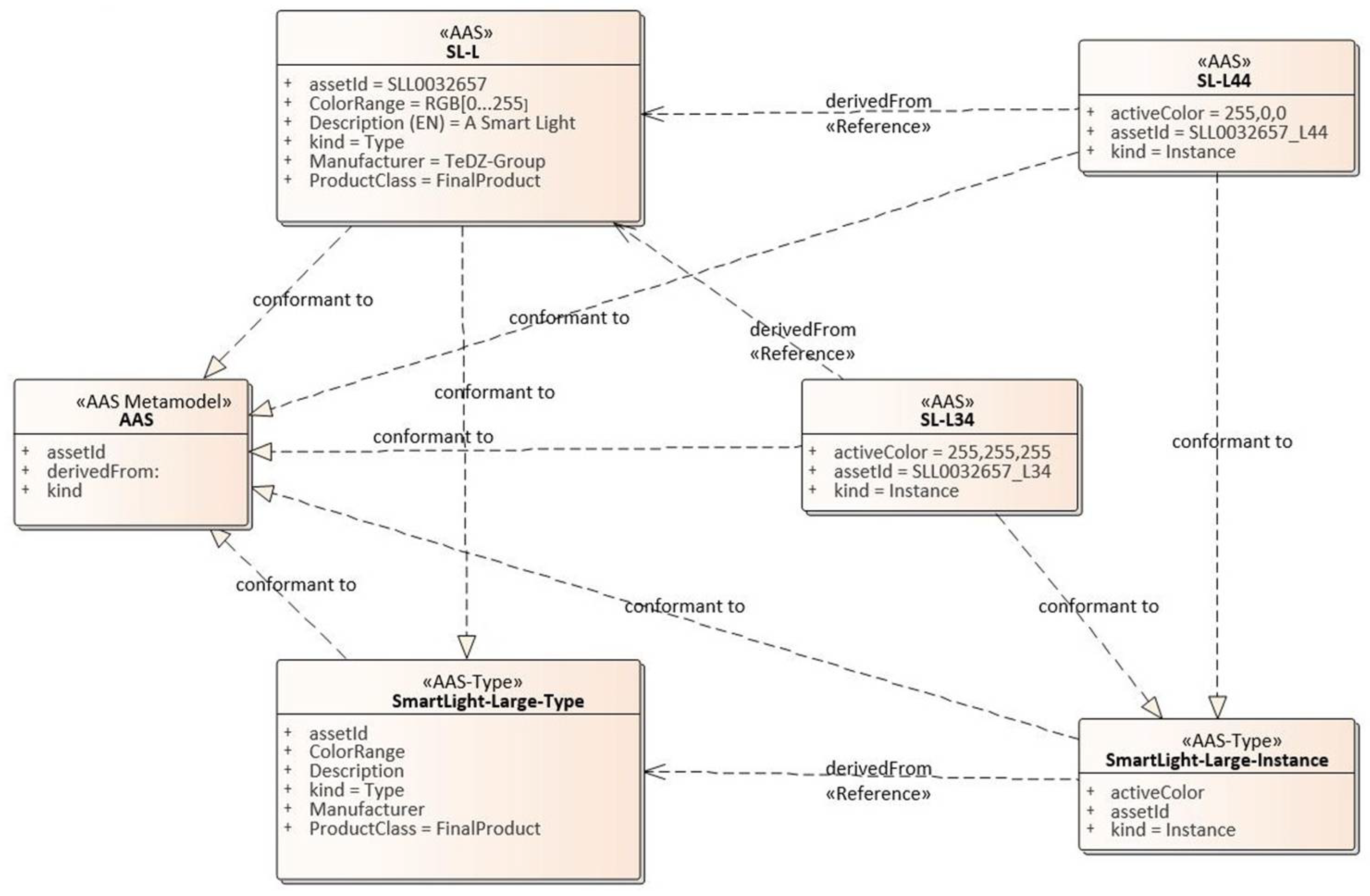
Figure 12.
Example production infrastructure based on several AASs.
Publisher’s Note: MDPI stays neutral with regard to jurisdictional claims in published maps and institutional affiliations. |
© 2021 by the authors. Licensee MDPI, Basel, Switzerland. This article is an open access article distributed under the terms and conditions of the Creative Commons Attribution (CC BY) license (https://creativecommons.org/licenses/by/4.0/).
Share and Cite
MDPI and ACS Style
Deuter, A.; Imort, S. Product Lifecycle Management with the Asset Administration Shell. Computers 2021, 10, 84. https://0-doi-org.brum.beds.ac.uk/10.3390/computers10070084
AMA Style
Deuter A, Imort S. Product Lifecycle Management with the Asset Administration Shell. Computers. 2021; 10(7):84. https://0-doi-org.brum.beds.ac.uk/10.3390/computers10070084
Chicago/Turabian StyleDeuter, Andreas, and Sebastian Imort. 2021. "Product Lifecycle Management with the Asset Administration Shell" Computers 10, no. 7: 84. https://0-doi-org.brum.beds.ac.uk/10.3390/computers10070084
Note that from the first issue of 2016, this journal uses article numbers instead of page numbers. See further details here.