Deploying CPU-Intensive Applications on MEC in NFV Systems: The Immersive Video Use Case
by
 ,
,
Giorgio Cattaneo
1, 
Fabio Giust
2,
Claudio Meani
1,
Daniele Munaretto
2 and
Pietro Paglierani
1,* 1
Italtel S.p.A, 20190 Settimo Milanese (MI), Italy
2
Athonet SRL, 36050 Bolzano Vicentino (VI), Italy
*
Author to whom correspondence should be addressed.
Computers 2018, 7(4), 55; https://doi.org/10.3390/computers7040055
Submission received: 26 September 2018
/
Revised: 19 October 2018
/
Accepted: 22 October 2018
/
Published: 26 October 2018
(This article belongs to the Special Issue Mobile Edge Computing)
Abstract
:Multi-access Edge Computing (MEC) will be a technology pillar of forthcoming 5G networks. Nonetheless, there is a great interest in also deploying MEC solutions in current 4G infrastructures. MEC enables data processing in proximity to end users. Thus, latency can be minimized, high data rates locally achieved, and real-time information about radio link status or consumer geographical position exploited to develop high-value services. To consolidate network elements and edge applications on the same virtualization infrastructure, network operators aim to combine MEC with Network Function Virtualization (NFV). However, MEC in NFV integration is not fully established yet: in fact, various architectural issues are currently open, even at standardization level. This paper describes a novel MEC in an NFV system which successfully combines, at management level, MEC functional blocks with an NFV Orchestrator, and can neutrally support any “over the top” Mobile Edge application with minimal integration effort. A specific ME app combined with an end-user app for the provision of immersive video services is presented. To provide low latency, CPU-intensive services to end users, the proposed architecture exploits High-Performance Computing resources embedded in the edge infrastructure. Experimental results showing the effectiveness of the proposed architecture are reported and discussed.
1. Introduction
The recent rise of data-intensive services, such as video streaming, social networking, and gaming, has triggered an explosion of mobile traffic, with the specific need to achieve higher data rates per user. Concurrently, novel business segments—e.g., automotive, smart manufacturing, and healthcare—have contributed significantly to the demand for ultra-reliable low-latency and massive machine-type communications.
Forthcoming 5th Generation (5G) mobile networks are being designed to satisfy such requirements, and to take advantage of the convergence of the telecom world with the Cloud Computing paradigm [1,2].
The adoption of Cloud Computing in communication infrastructures addresses the need of telecom operators to cut operational costs, improve flexibility, and reduce service deployment time. In this context, Network Function Virtualization (NFV) and Software-Defined Networking (SDN) play a crucial role by enabling the deployment of network services as cloud applications in large, centralized data centers, usually located in the network core [3].
On the other hand, this widely acclaimed approach can provide unsatisfactory results whenever a service requires low response times and/or high data rates, due to bottlenecks in the data-path to or from end users.
Thus, pushed by the need to process data in proximity to consumers, network operators are carefully considering the deployment of Information Technology (IT) resources at the network edge, as envisioned by the Edge Computing paradigm [4].
Edge Computing makes it possible to minimize transmission delay and achieve high data rates locally. Furthermore, applications running at the edge can exploit specific real-time information provided by the Radio Access Network, such as radio link status or the geographic location of consumers [4,5].
To promote the adoption of Edge Computing, in 2014 the European Telecommunications Standards Institute (ETSI) launched the Mobile Edge Computing Industry Specification Group (ISG) Mobile Edge Computing (renamed Multi-access Edge Computing in 2016), which is releasing guidelines for the deployment of MEC systems in 4G and, in perspective, in 5G networks [6,7,8].
In this context, a topic of significant interest is the integration of MEC with NFV. Mobile network operators, in fact, aim to consolidate Virtual Network Functions (VNFs) and Mobile Edge (ME) apps on top of the same infrastructure, to maximize their return of investment in virtualization technology [9,10].
However, despite the considerable amount of work already done, the development of an MEC in an NFV system can still present many challenges, some of which (to the best of the authors’ knowledge) have not been adequately addressed yet.
The first difficulties typically encountered—as results clearly from Reference [10]—are at the architectural level, due to some known problems in integrating the MEC and NFV frameworks in accordance with the corresponding reference standards. Presently, ETSI Standardization groups focus on a list of fourteen MEC in NFV integration open issues, some of which could even require changes to the current MEC specifications [10]. Nonetheless, industrial players need to find practical solutions to such problems in the short term, to rapidly respond to the rising demand for commercial ME systems.
A second important aspect concerning MEC is how end users can effectively access the services offered by ME apps. Recently, consumers’ preferences have shown a shift from standard voice calls and text messaging to advanced video activities and social networking, carried out through their tablets or smartphones [11,12]. During sporting events, concerts, or in touristic locations, consumers increasingly often wish to originate and share media contents in groups of peers, rather than merely receiving them from a centralized media distribution system.
However, most of the works available concerning MEC focus on traditional video networking functionalities, such as video caching or video streaming [5,13,14,15,16,17,18,19,20,21,22,23,24]. Conversely, the problem of successfully combining end-user apps and ME apps to provide interactive and immersive video services to consumers on a peer-to-peer basis is a topic that has received little attention from researchers so far.
Finally, to provide high-resolution video services, ME apps necessarily originate CPU-intensive workloads. Unfortunately, moving resource-demanding video applications from large data centers to the edge infrastructure can be a difficult task. The IT resources available at the network edge are often subject to strict constraints in terms of power consumption, thermal dissipation, or space occupation, which can severely limit their compute performance. In this case, the use of High-Performance Computing (HPC) devices, such as Graphics Processing Unit(s) (GPUs), could provide significant benefits [25]. Nonetheless, though some results about the use of offloading techniques in virtualization infrastructure are available [22,25], the analysis of the computing performance achievable by ME systems when performing video-processing tasks has not been thoroughly analyzed yet.
As a contribution to the development of an effective MEC in an NFV framework, this paper describes a novel experimental ME system, which can provide some simple and effective solutions to the problems discussed above.
At the management level, the proposed system combines some specific MEC functional blocks with a standard NFV Orchestrator (NFVO, [26]) and solves most of the main practical integration issues listed in Reference [10]. Moreover, the resulting architecture can straightforwardly re-use available NFV frameworks and makes it possible to easily upgrade already deployed NFVOs into ME systems, capable of running both standard VNFs and ME apps.
As an example, this paper focuses on the Italtel i-Enhanced Video System (EVS), an ME app specifically developed to provide innovative video services to consumers during crowded events [24]. Besides demonstrating the capabilities of the system to manage ME apps, the use of i-EVS also highlights the advantages that MEC can provide compared to a standard NFV framework in the provision of an immersive video-processing appliance.
The i-EVS services can be easily accessed through any browser. Nonetheless, to improve consumers’ Quality of Experience (QoE), an ad hoc end-user app downloadable on end-user devices has been developed, to demonstrate how an end-to-end integrated service can fully exploit the potentialities offered by MEC for peer-to-peer media content sharing.
A prototypal version of the proposed architecture has been implemented in a real-life testbed, and integrated into a 4G Long Term Evolution (LTE) network, by adopting a “Distributed SGW with Local Breakout (SGWLBO)” approach, which can evolve to a 5G network architecture [27].
The virtualization infrastructure has been realized using portable servers hosting GPUs, to achieve the required compute performance and satisfy the energy consumption and space occupation constraints typically encountered at the network edge. In particular, the use of GPUs is analyzed, and the gain they can provide in terms of processing performance, energy consumption, and space saving quantitatively is evaluated through ad hoc experiments.
The structure of the paper is as follows. The next section introduces the main MEC and NFV concepts and summarizes the state of the art in MEC-NFV integration. Moreover, it provides a survey of traditional video-processing services at the network edge, to highlight the advances made possible by the proposed approach. Section 3 describes the presented ME system architecture and analyzes in detail two fundamental ME app management activities, i.e., on-boarding and instantiation, to show how the main MEC in NFV integration issues can be overcome. Section 4 describes the overall i-EVS frameworks, consisting of an ME app running on top of the proposed ME system, and an end-user app to be downloaded on end users’ devices. Finally, in Section 5, an overview of the implemented physical testbed is given, and the obtained experimental results are summarized and discussed. Such results can represent a benchmark to characterize the computing performance achievable at the network edge in the presence of energy consumption constraints.
The activities described in this study have been carried out within the European Commission Horizon 2020 5G Essence project, under Grant Agreement No. 761592.
2. Related Work
MEC and NFV are complementary frameworks, defined in many quite complex ETSI specifications. For the sake of clarity and completeness, this section begins by summarizing the most relevant MEC and NFV concepts and highlights their common aspects and significant differences.
2.1. The ETSI MEC Framework and Its Reference Architecture
MEC enables the implementation of ME apps as cloud applications, running on top of an open infrastructure located in proximity to end users.
The MEC reference framework is described in References [6,7,8]. In particular, Reference [6] provides a glossary of terms, Reference [7] specifies MEC requirements, and Reference [8] details the overall architecture, its constituting elements, and the related reference points.
MEC standardization activities are still ongoing; hence, interested readers should rely on the official ETSI specifications for an updated description of the framework (all the documents published by ETSI MEC are available at https://www.etsi.org/technologies-clusters/technologies/multi-access-edge-computing under the “Specifications” tab.). Nonetheless, below, we will briefly summarize some concepts extensively used throughout this paper.
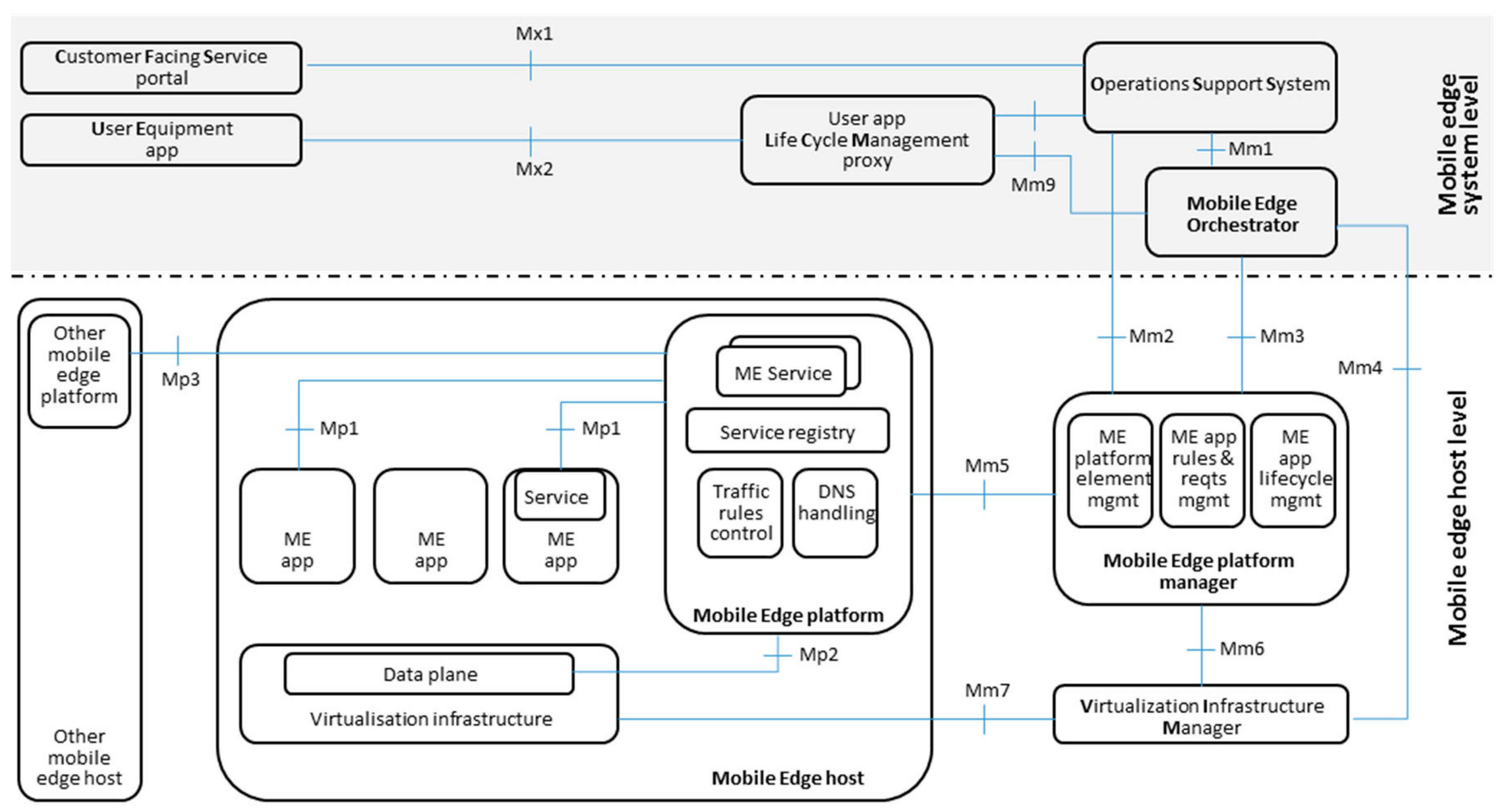
Figure 1 shows the reference architecture of an ME system, partitioned into the network, host, and system levels [8]. The Network level must provide connectivity to ME apps; to this end, it can use different access technologies, including 3GPP mobile networks or WIFI. Since no MEC functional block or reference point is specified at the Network level, this part is not included in the figure.
From the functional point of view, an ME system can be further divided into two major parts, i.e., the ME host, and the management blocks necessary to run ME apps in a mobile network.
2.1.1. The ME Host
The ME host consists of the ME platform and the virtualization infrastructure that provides compute, storage, and network resources to ME apps [8].
The ME platform offers the functionalities required by ME apps to implement services. It is responsible for the local handling of the Domain Name System (DNS) protocol, and for enforcing the related traffic routing rules in the MEC data plane [10].
ME apps are instantiated on the virtualization infrastructure upon a validated request originated by ME management blocks. After instantiation, they register and discover services, communicating with the ME platform through the Mp1 reference point [28]. MEC defines two other reference points related to the ME platform, namely, Mp2 and Mp3. Through Mp2, the ME platform controls the MEC data plane, while Mp3 can be used to connect different ME platforms.
2.1.2. ME Management Blocks
ME management blocks operate at both the system and host levels. At the system level, the core component is the ME orchestrator, which manages the ME app lifecycle, application rules, and requirements, and keeps track of the instantiated ME apps. To this end, it interacts with the management blocks at the host level through Mm3 and Mm4.
The ME orchestrator must ensure that ME app requirements (such as latency or throughput) are fulfilled; thus, it selects the appropriate ME host on which ME apps should run.
The other system level management blocks of interest for this paper are the Operations Support System (OSS) and the Customer Facing Service (CFS) portal. OSS is in charge of fault, configuration, and performance management. It receives requests to instantiate and terminate ME apps from the CFS portal, and assists the orchestrator, via Mm1, in deploying them at the desired network location.
The host level includes two management blocks, i.e., the ME platform manager, and the Virtualization Infrastructure Manager (VIM). The ME platform manager provides:
- (i)
- ME App lifecycle management (i.e., instantiation, termination, etc.);
- (ii)
- The ME platform Element Management System (EMS);
- (iii)
- ME app policy management functions (i.e., traffic rule, DNS configuration, etc.).
The ME platform manager communicates with the OSS via Mm2 for fault, configuration, and performance management, and with the ME orchestrator via Mm3 for lifecycle management and policy provision.
As in NFV, the VIM is responsible for the virtualized resources used by ME apps [29]. Moreover, it can provide fault and performance monitoring capabilities to the ME orchestrator through Mm4.
2.1.3. Other MEC-Related Work
Besides architectural aspects, MEC also defines the Application Programming Interfaces (APIs) that should be used at its reference points: to this end, Reference [30] provides a general overview of the RESTful ME service APIs, while specific examples APIs are given, for instance, in References [31,32].
Additionally, ETSI MEC publishes informative white papers. In particular, Reference [27] describes several different approaches to deploying an ME system in a 4G mobile network, to offload “over the top” ME apps from the cumbersome task of dealing with the tunneling protocols used in mobile networks.
The ME system proposed in this paper adopts the insertion approach usually referred to as “Distributed SGW with Local Breakout” [27], which will be described in detail in the next sections.
The integration of the MEC and NFV framework is specified in Reference [10]. We will briefly summarize the state of the art on this topic in Section 2.3, after introducing some relevant NFV concepts.
2.2. ETSI NFV Reference Architectural Framework
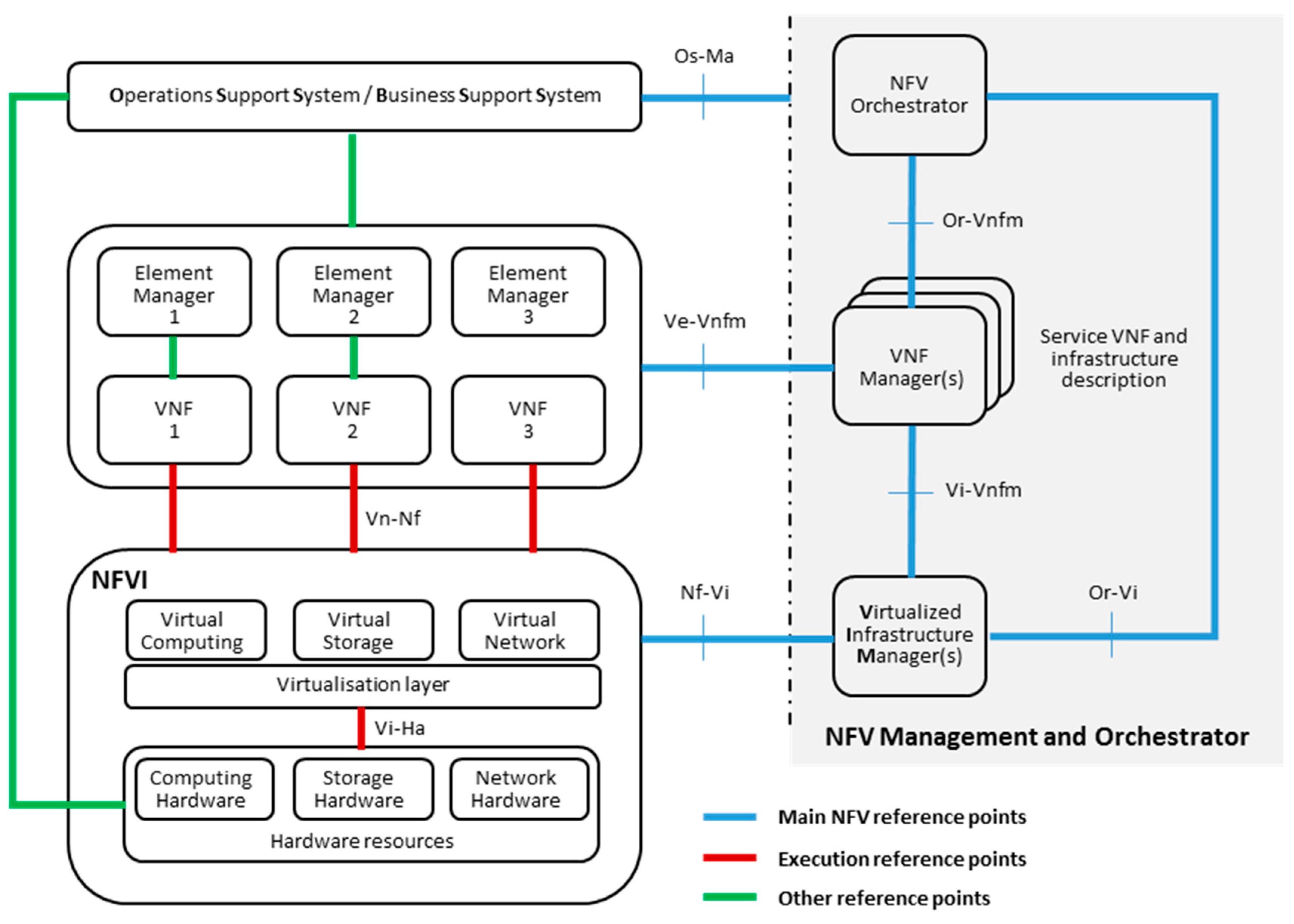
The NFV framework, shown in Figure 2, makes it possible to decouple applications from the underlying physical infrastructure, thus transforming network functions previously implemented on bespoke hardware into VNFs.
A VNF runs as a software appliance over an NFV Infrastructure (NFVI) [30]; it may have one or multiple internal VNF components (VNFCs), each running in a virtual machine, and can be chained with other VNFs and/or Physical Network Functions to realize a network service (NS).
A major element in NFV is the Management and Orchestration (MANO) block, composed of the Virtualized Infrastructure Manager (VIM), the VNF Manager (VNFM), and the NFV Orchestrator (NFVO). It orchestrates the allocation of resources required by NSs and VNFs, and manages their lifecycle and the NFVI.
To describe the on-boarding process of ME apps into an ME system, we will make extensive use of the concept of the VNF Package [33,34]. A VNF Package contains all the necessary files and meta-data descriptors required to validate and instantiate a VNF, i.e.:
- The VNF Descriptor (VNFD);
- The software images needed to run the VNF;
- The Manifest file that provides package integrity and authenticity;
- (Optional) additional files to manage the VNF.
The VNF Descriptor is a template that defines the necessary resources to run the VNF, and its behavior in lifecycle management. It specifies connectivity, interfaces, and performance requirements to establish the Virtual Links (VLs) between VNFC instances, or between a VNF instance and the endpoints to other VNFs.
To manage NSs, the NFV MANO relies on the NS Descriptor (NSD). The NSD references the descriptors of all the components of an NS, including the VL Descriptors and the VNF forwarding graph, which defines the topology of the NS [35].
2.3. MEC and NFV Framework Integration
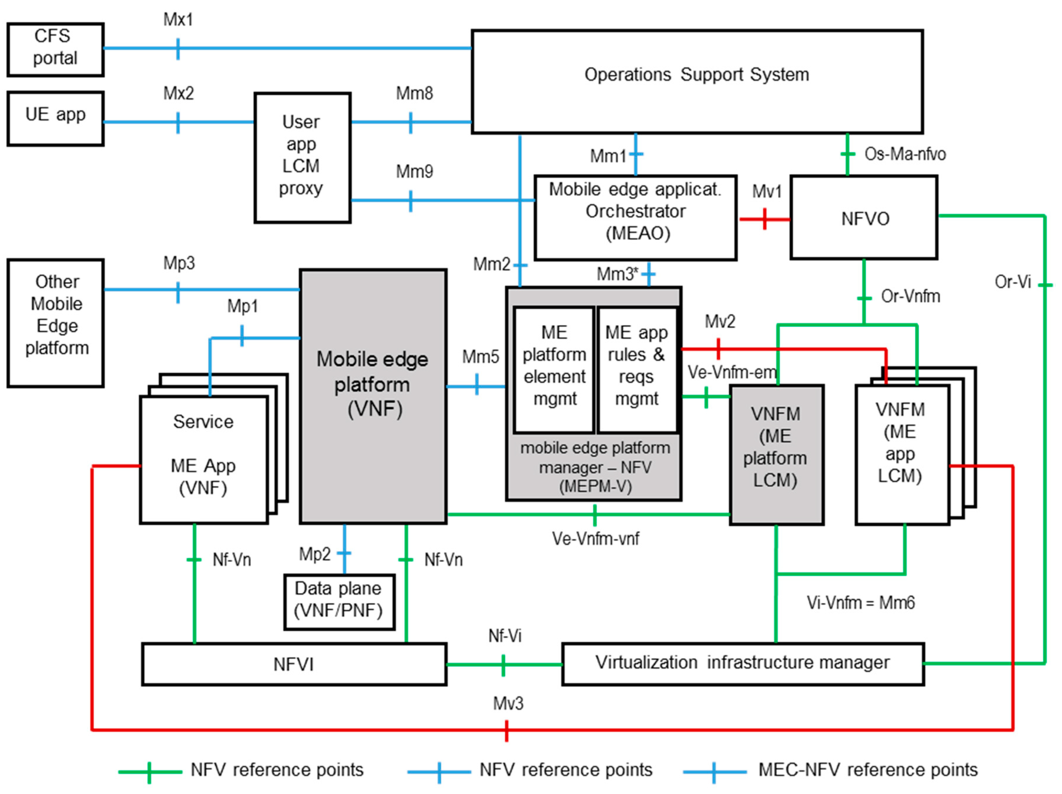
ETSI MEC has carried out a specific activity to integrate MEC and NFV; Reference [10] summarizes the results obtained and Figure 3 shows the proposed MEC in NFV reference architecture.
The ETSI MEC in an NFV framework relies on three basic assumptions:
- The ME platform is deployed as a VNF;
- ME apps are deployed as VNFs;
- The virtualization infrastructure is deployed as an NFVI, and is managed by a VIM.
Unfortunately, such simple statements have a significant impact on the original MEC architecture outlined in Reference [8], bringing about relevant changes in the scheme shown in Figure 1 [10].
In particular, in MEC in NFV, the ME host is no longer present, since both the ME platform and the ME apps run as VNFs in the NFVI. Moreover, the ME platform manager becomes the “Mobile Edge Platform Manager—NFV” (MEPM-V) shown in Figure 3, delegating application lifecycle management to one or more VNFM(s). Finally, the Mobile Edge Orchestrator is transformed into the “Mobile Edge Application Orchestrator” (MEAO) [10].
The MEAO is connected with the MEPM-V through Mm3, to carry out configuration activities. In Figure 3, Mm3 is indicated as Mm3*, with an asterisk to highlight that this reference point will necessarily be changed, due to the split between MEPM-V and VNFM introduced by Reference [10].
The integration of MEC and NFV has attracted the attention of many researchers, and a state-of-the-art analysis can be found in References [9,36,37]. The work described in Reference [9] provides an overview of MEC, and discusses the interaction with NFV, while Reference [36] introduces the adoption of the Open Baton orchestrator in MEC. However, Reference [36] focuses on supporting the deployment of container-based network services, while the MEC management aspects considered in this work are not discussed. Reference [37] proposes NFVO+, a single enhanced NFV MANO modified to deal both with VNFs and ME apps. The present paper, conversely, aims to present an MEC part that is agnostic with respect to the adopted NFV framework, and can thus be combined with any, even already deployed, NFVO.
On the application side, MEC has been proposed in many fields, as a means to provide enhanced services to end users. In particular, MEC-based video applications have been widely investigated in the literature. In the following section, we provide a brief survey of the of the state of the art of video services and MEC, to highlight the advances that the framework proposed in this paper can offer with respect to already available solutions.
2.4. The Immersive Video Use Case
High-resolution video processing and Content Delivery Networks (CDNs) can greatly benefit from MEC and NFV. References [5,13,14,15,16,17,18,19,20,21,22] summarize some relevant results in this field. In particular, Reference [13] shows the improvement in QoE perceived by users when CDNs are extended to the edge through the use of NFV and cloud technologies. Conversely, Reference [14] proposes the concept of CDN as a service, focusing on the optimized placement of Virtual Machines hosting caches, transcoders, and streamers, to minimize costs and maximize streaming QoE.
To emphasize the benefits of an MEC in an NFV platform compared to a traditional video distribution service, Reference [15] exploits the users’ QoE and bandwidth as performance indexes. Reference [16] considers the concept of on-the-fly-transcoding and proposes a framework in which the network edge plays a leading role in customizing the video format, based on user’s expectations.
The advantages of a cloudlet network in a video streaming application are discussed in References [17,18].
Reference [5] provides a state-of-the-art survey on research efforts in MEC, pointing out challenges, open issues, and opportunities. In this regard, Reference [19] defines the differences between an MEC and a Cloud Radio Access Network (RAN) approach, demonstrating that they are not exclusive technologies; rather, they complete each other and can work together in a heterogeneous mix.
The subject of real-time video transcoding in a distributed heterogeneous environment is addressed in Reference [20]. The performance of the proposed system scales as the number of nodes increases, up to the point that the scheduler for video frames distribution becomes a bottleneck.
Previous works carried out by some of the authors, such as References [21,22], are related to hardware and software acceleration at the network edge, and GPU utilization in NFV-only environments; Reference [23] discusses the use of GPUs to accelerate the VP8 Video encoder, while Reference [24] introduces immersive video services.
All the discussed works focus on traditional video networking applications, in which consumers receive the selected media contents from a central or distributed delivery system. This paper goes beyond such results since it addresses services in which users can originate and share high-quality media contents (also in real-time), by using a specific ME app (i-EVS) on top of an integrated MEC in an NFV environment equipped with High-Performance Computing (GPUs), and a related end-user app which runs on the end users’ devices.
3. Overall Architecture of the Proposed ME System
This section introduces the block scheme of the proposed ME system architecture and illustrates some relevant aspects of its behavior through the description of two fundamental activities it can carry out.
3.1. The ME System Block Diagram
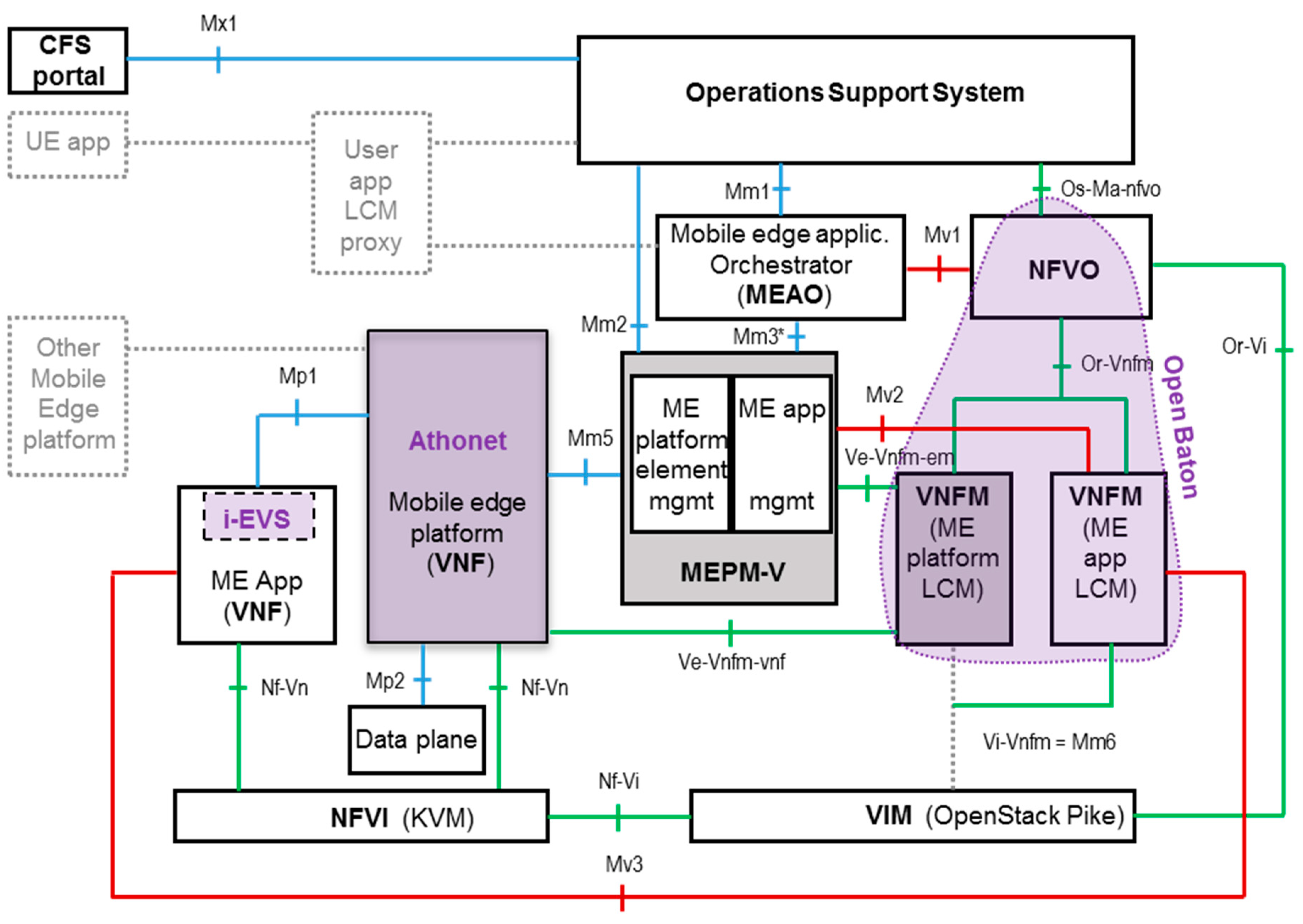
The block diagram in Figure 4 summarizes the overall architecture of the proposed ME system. At the management level, it includes elements from a standard NFV framework, complemented with three blocks that provide specific MEC functionalities, i.e., the CFS portal, the OSS, and the MEAO.
The NFVO is provided by Open Baton, an available and well-established open source NFV framework [26]. The Open Baton NFVO includes the VNF Managers (VNFMs). However, no restriction applies to this aspect, and external VNFMs could also be adopted.
The SGWLBO VNF shown in Figure 4 implements both the ME platform and the ME data plane. In this study, the SGWLBO VNF and its Element Management System are provided by Athonet. They make it possible to integrate the ME system into a 4G LTE network, in accordance with the “Distributed SGW with Local Break Out” scheme defined in Reference [27]. A detailed description of the SGWLBO VNF block is given in Section 3.4.
The MEAO invokes operations towards the NFVO adopting a master/slave approach via the MEC Mv1 reference point [8]. To use an ETSI-standard NFVO, we will assume Mv1 equivalent to the ETSI NFV Os-Ma-nfvo reference point [29]; thus, Mv1 inherits the interfaces and operations defined for Os-Ma-nfvo [10]. For the same reason, Mv2 and Mv3 correspond to the NFV reference points Ve-Vnfm-em and Ve-Vnfm-vnf, respectively ([10], issues #4 and #5).
The MEPM-V block is given by the combination of the Element Management Systems of the SGWLBO VNF and the i-EVS VNF; it interacts with the MEAO through the modified Mm3* reference point [10]. Additionally, Mm3* inherits the configuration requirements, originally defined for Mm2 in [7,10].
The NFVI is a standard virtualized infrastructure in accordance with ETSI NFV. The NFVI used includes computing Hardware (HW) accelerators, in particular GPUs by NVIDIA. The hypervisor is KVM, and GPUs are assigned to the corresponding VNFs using the PCI passthrough mode [25]. The VIM is Openstack [38].
To better clarify the functionalities offered by the proposed framework, in the following paragraph we describe a possible realistic scenario of its use.
3.2. ME App On-Boarding and Instantion Example in Crowded Event Scenarios
Service providers and app developers interact with ME systems through the CFS portal, which represents the entry point for third parties, and is intended to reproduce the quite successful approach adopted by public cloud platforms.
Through the CFS portal, service providers can instantiate ME apps, such as the i-EVS, in specific venues where a crowded event might occur: a stadium for a concert or a sporting match, a touristic location at seasonal peak periods, a mall, etc. [24]. In this way, participants at the event can benefit from the high-value services provided by ME apps running on top of local IT resources.
Very often, the manager of the venue—e.g., a commercial landlord, enterprise, or municipality, could be the owner of the local infrastructure and may be willing to rent it to different telecom operators. In this case, it (or a collaborating service provider) assumes the role of Neutral Host, as envisioned and supported by organizations such as the Small Cell Forum [39]. The Neutral Host provides services to different operators wishing to exploit the infrastructure in a particular location, and collaborates in the definition of a solution that is commercially and technically viable for operators.
In this paper, however, for simplicity reasons, we will assume that the entire network, the ME system and the underlying network infrastructure are provided by a single telecom operator, responsible for the entire network up to the infrastructure at the edge.
This scenario clearly highlights the importance of two types of interaction of service providers and developers with the ME system, i.e., Me app on-boarding (performed by the developer) and ME app instantiation (performed by the service provider). We will describe such interactions in detail in the following paragraphs.
3.2.1. ME App On-Boarding
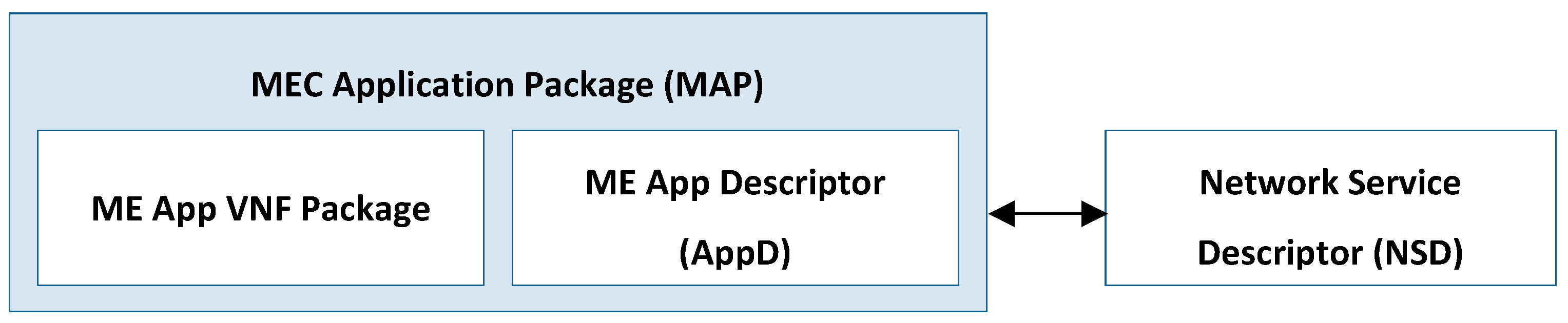
To on-board their ME apps to an ME system, developers must create an MEC Application Package (MAP), and upload it through the CFS portal.
The package structure used in this study complies with the Cloud Service Archive (CSAR) format [34], a well-known format commonly used in cloud applications, and also adopted in NFV.
As shown in Figure 5, the MAP must contain the specific ME app VNF package required by NFV, and an additional ME App Descriptor (AppD) file, as envisioned by MEC [10]. Since ME apps appear like VNFs included in an NS towards the NFVO, developers must on-board their MAP together with a corresponding NSD, to provide the NFV-related information [10].
The AppD file contains information about the ME app, which is relevant for the ME system, but cannot be included in a standard VNFD. Typically, the AppD includes DNS rules, traffic rules, or latency parameters. Interested readers can find a detailed comparison of AppD and VNFD in Reference ([10], page 25).
In this study, we will restrict the discussion to DNS and traffic routing rules, and we will not consider latency or other parameters. Nonetheless, the extension of the analysis to a wider set of parameters is straightforward. Moreover, in the example in question, a DNS rule will be expressed as a single record, consisting of a Fully Qualified Domain Name (FQDN), indicating a host running the ME app, and its corresponding IP address [8]. Thus, the AppD must only contain the information necessary for defining the appropriate DNS and traffic routing rules, which will properly steer the consumer data traffic.
In most cases, the FQDN associated to an ME app is known a priori, and can be straightforwardly included into the ME AppD by the developer. Conversely, the corresponding IP address could be unknown at the on-boarding time, as it could be dynamically assigned by the NFV MANO to the virtual machine running the ME app VNF only after its instantiation.
To overcome this problem, in this study we have extended the AppD structure to also contain a reference to the specific Connection Point of the ME app VNF, to which the IP address of interest will be assigned. Such a Connection Point is defined in the ME app VNFD and is therefore available a priori to the developer.
In this way, at the end of the instantiation process, the MEAO can query the NFVO to retrieve the Connection Point IP address, and finally create the required DNS rule for any instance of the ME app.
In the i-EVS on-boarding example considered, the FQDN associated with the ME app is “db.ievs.italtel.com” (as will be described below), and the Connection Point of interest is the one assigned to one VNFC of the i-EVS VNF (i.e., the db VNFC). We will describe in detail the mechanism used by the MEAO to retrieve the IP address of the referenced Connection Point in the next paragraph.
The on-boarding process continues with the OSS on-boarding the validated MAP to the MEAO through Mm1. The MEAO must be able to analyze the MAP, and separate the NFV-related components used by the NFVO from the ME AppD file that will be stored in the MEAO itself.
The MEAO on-boards the i-EVS VNF package and the corresponding NSD to the NFVO according to the operations associated with the standard NFV reference point Os-Ma-nfvo [40,41]. In fact, the “NSD Management” and “VNF Package Management” interfaces of the Os-Ma-nfvo reference point can specifically perform such tasks.
The MEAO maintains the information that is not pertinent to NFV in the AppD file. Moreover, it creates and maintains the relationship between AppD, the VNF Package and NSD for each on-boarded ME app.
3.2.2. ME App Instantiation
After the on-boarding process has been completed, a service provider can instantiate an ME app of interest on a selected NFVI, by using the CFS portal and through the OSS.
Upon receiving an ME app instantiation request, the MEAO invokes standard operations towards the NFVO through Mv1 (see Figure 4), which is assumed to be equivalent to the standard NFV Os-Ma-nfvo reference point [40,41]. The MEAO also performs additional activities, to complete the ME app instantiation process for all those aspects falling outside the scope of NFV and that an ETSI-standard NFVO usually cannot deal with [10].
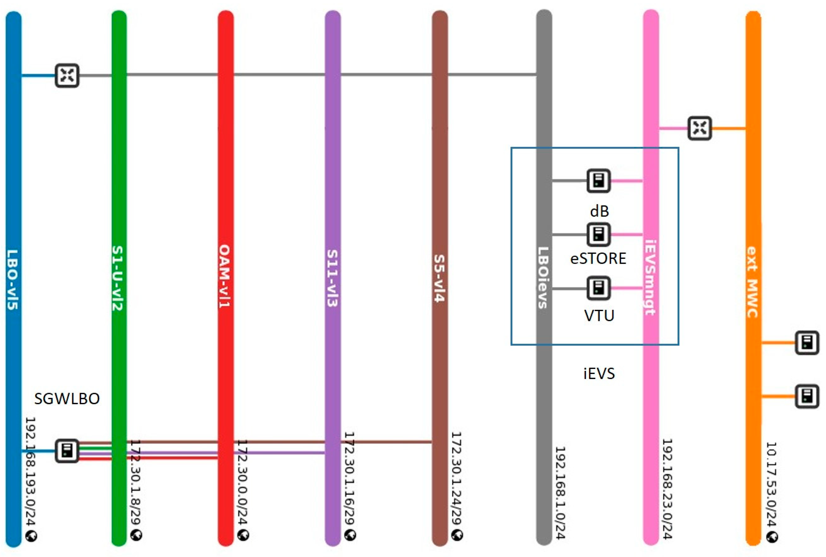
To focus on the interactions between MEAO and NFVO, we will make the simplifying assumption here (illustrated in Figure 6) that the SGWLBO VNF, with five related VLs—namely, S1-U-vl2, S5-vl4, LBO-vl5, S11-vl3, and OAM—is included in an NS, which is already in service when the ME app instantiation process starts. We will refer to this NS as SGWLBO NS.
The dependency between the ME platform VNF and the ME app VNFs is still an open issue ([10], key issue #2), which the assumption adopted can simply overcome. This solution does not preclude the instantiation of a serving ME platform and multiple ME apps in the same NS. Nonetheless, the discussion of such a case and all its implications is fairly complex, and would go far beyond the scope of this paper; hence, it will not be analyzed here.
Figure 6 shows the instantiated SGWLBO NS, as visualized by the OpenStack dashboard. The S1-U-vl2 VL (represented as a vertical green bar, second from the left) delivers S1-User-Plane (S1-U) data, while S5-vl4 carries S5 data; S11-vl3 transports network control messages, while the OAM VL connects the SGWLBO VNF to its Element Management System.
In LTE networks, the S1-U interface is between the eNodeB and the S-GW, while S5 is between the SGW and the Packet-data-network Gateway (PGW) functional blocks [42,43]. Both S1-U and S5 make use of the General Packet Radio Service (GPRS) Tunneling Protocol (GTP) for the user plane, i.e., GTP-U [43].
GTP-U permits many tunnels between sets of endpoints. On S1-U and S5, the IP packets sent and received by end users travel within such specific tunnels, set up under the supervision of the network control plane; hence, they cannot be directly processed by ME apps, which typically do not have the necessary control information to deal with GTP-U [27]. Conversely, the SGWLBO VNF, which includes the MEC data plane and cooperates with the SGW functional block, can terminate GTP-U tunnels, and thus make available “de-tunnelized” plain IP user data on the LBO-vl5 link (leftmost blue bar in Figure 6).
In this study, as suggested by Reference [10], ME app VNFs are included in NSs, consisting of one (or more) VNF, and a set of corresponding VLs, which, during the instantiation process, can be suitably connected to the ones offered by the SGWLBO NS. The final result of this process is summarized in Figure 6, which, besides the SGWLBO NS, also shows the instantiated NS, including the i-EVS ME VNF.
The i-EVS VNF consists of three VNFCs, namely dB, VTU, and eSTORE. Besides two management VLs (the orange and pink bars in Figure 6), the corresponding NS also includes the LBOievs VL. From the previous discussion, one can easily verify that consumer data traveling through the S1 and S5 interfaces in the mobile network can be made available to the i-EVS ME VNF as plain IP data through the interconnection of LBO-vl5 with the LBOievs VL.
In the proposed architecture, the MEAO requires the NFVO to set the NS including the ME app VNF through standard NFV operations [40,41]. Specifically, the MEAO relies on the interface “NS Life Cycle Management” of the Os-Ma-nfvo reference point, which makes it possible to invoke NS lifecycle management operations towards the NFVO [40,41].
The MEAO interaction with the NFVO can thus be summarized by the following steps:
- MEAO invokes the instantiation of the NS, including the ME app VNF;
- MEAO subscribes to NFVO notifications, related to such NS;
- MEAO queries the NFVO to retrieve the required information, related to this NS.
The notification originated by the NFVO at the end of the NS instantiation process is the trigger to start the third step of the above procedure.
The MEAO uses the information retrieved from the NFVO to complete the ME app instantiation. In the example shown in Figure 6, once the MEAO has retrieved the dB Connection Point IP address, it can create the corresponding DNS and traffic routing rules. Such information is sent to the Element Management System of the SGWLBO VNF via Mm3* [10]. In this way, the ME platform can set the DNS server included in SGWLBO, to properly forward the user data traffic to the corresponding i-EVS instance.
3.3. The SGWLBO Data Plane
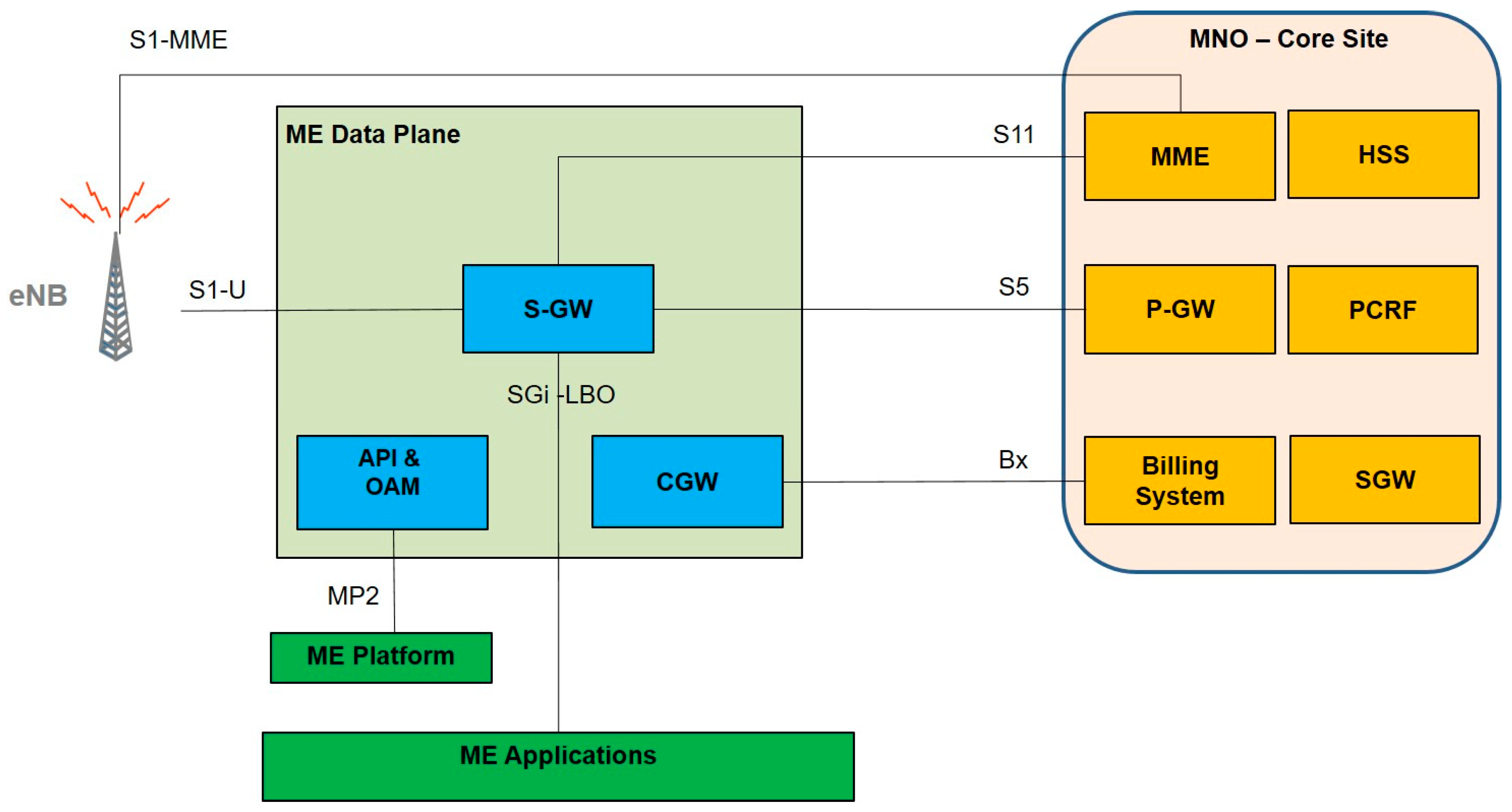
In the ME system presented in this paper, the ME platform and data plane are both implemented in the SGWLBO VNF provided by Athonet. In particular, SGWLBO must carry out the non-trivial process of terminating GTP-U tunnels. In the literature, different approaches have been proposed for the appropriate handling of GTP-U data [27]. Among these, the “Local Breakout at the SGW” scheme is a new architecture for MEC, which enables users to reach, over the same Access Point Name (APN), both the ME apps and the operator’s core site applications [27,43].
In this approach, the ME data plane is co-located and relies on the SGW functional block of the LTE network architecture [43]. Figure 7 provides a block scheme describing this approach, in which the distributed SGW is at the edge together with the ME platform.
The traffic steering process uses the SGi-Local Break Out (SGi-LBO) interface, which allows for traffic separation and a 3GPP-compliant level of security [27]. Such an interface corresponds to the instantiated LBO-vl5 VL shown in Figure 6, and discussed in the previous sub-section.
The SGW-LBO approach offers mobile operators the possibility to steer consumer data traffic based on any combination of the below policy set:
- APN and user identifier;
- Application protocol;
- Destination IP address;
- Other IP flow filters, such as IP version and Differentiated Services Code Point marking.
Using this approach, some basic functionalities, such as billing (as shown in Figure 7) or lawful interception capabilities [27], can straightforwardly be made available to telecom operators. This is a practical advantage of significant importance in real-life deployments, which could be not easily offered if other approaches, such as “Bump in the wire”, are adopted. For a more detailed comparison of the different approaches to ME system deployment, interested readers can refer to Reference [27].
3.4. High-Performance Computing Resources Management for CPU-Intensive ME Apps
One of the differentiating aspects that characterizes the proposed ME system is the presence of High-Performance Computing resources (i.e., GPUs) in the NFVI that hosts the ME apps. To manage such resources, the presented system exploits the PCI passthrough mode [25], and the standard capabilities offered by the OpenStack VIM; in particular, it relies on OpenStack flavors [38], which are used to define the compute, memory, and storage capacity of a virtual server.
To manage HPC resources in the NFVI, two preliminary steps must be carried out. First, in the Openstack VIM, the descriptor of HPC-equipped compute nodes must signal the presence of GPUs, by including an ad hoc referencing alias [38]; then, a specific OpenStack flavor containing the same alias must be created.
The VNFD of any VNF that could require GPU resources then has the possibility to indicate that specific flavor and thus require a compute node equipped with GPUs for the execution of the described VNF.
For the sake of brevity, we will skip further details, since flavor management in OpenStack and its use in VNFD is a well-established topic, which is out of the scope of this paper. Interested readers can refer to Reference [38].
The use of HPC resources in the NFVI makes it possible to combine the advantages offered by NFV with high computing performance levels even in the presence of energy consumption or space occupation constraints, as will be shown in Section 5.
4. The Immersive Video ME App
The i-EVS framework, developed by Italtel, can provide immersive video services at the network edge [24]. It consists of two main parts:
- The i-EVS ME App;
- The i-EVS End-User App.
The ME app can provide real-time or file-based media content sharing capabilities to consumers. Furthermore, it can manage users and groups, by storing and maintaining updated the related information in an appropriated database [24].
The end-user app runs on end users’ smartphones or tablets, where it can be downloaded on demand. It offers the possibility to register to i-EVS, and to create groups of users who can share media contents, off-line or in real-time. The main features of the i-EVS ME app and the end-user app, as well as their interactions, are briefly summarized in the following paragraphs.
4.1. The i-EVS ME App
The i-EVS ME app consists of three VNF components (VNFCs), namely the “VTU” Media Engine (ME), the “eSTORE” repository, and the “dB” database.
4.1.1. VTU VNFC
The VTU, shown in Figure 8, provides three basic functionalities:
- Video transcoding capabilities;
- Video streaming capabilities;
- System monitoring functionalities, to support the system maintenance process.
The VTU can convert video streams from one format to another, through transcoding, transrating, and scaling operations (below, the term “transcoding” includes transrating and scaling operations) [24]. Depending on the required service, the source video sequence could reside as a pre-recorded file on a storage system, or come as a real-time packet stream. The requested transcoding service could be mono-directional, as in video stream distribution applications, or bi-directional, as in real-time videoconferencing [24].
The VTU supports the most popular video codecs, such as H.264, H.265, and VP8/VP9. The VTU takes advantage of the potential presence of NVIDIA GPUs to improve overall performance and efficiency.
Video streams published by users are recorded by the VTU and saved in a distributed storage system (eSTORE), to be shared at a later time. In this way, pre-recorded video contents can be streamed to single users, to an entire group, or to all the users.
The VTU can also offer system managers monitoring data, to monitor the VTU status and performance during service, collecting data to a local database [24].
4.1.2. The eSTORE VNFC
The eSTORE VNFC offers local storage capabilities to groups of users. In this way, the operation of content upload and/or download to a storage system can be significantly accelerated, since it can be carried out without accessing the core network. This feature is particularly relevant during crowded events, when the backhaul connection becomes a contended resource that can originate bottlenecks for any activity involving the core network [24].
4.1.3. The dB VNFC
The dB VNFC collects and monitors relevant information about users and groups, which have registered to the i-EVS system.
When a user connects to the local access network for the first time, it can download the end-user app. The next step is registration to the system, through which the user is permanently identified by a name and/or nickname. The interaction between the end-user app and the dB VNFC allows users to create a group where video contents can be shared. For each user, the database stores all the relevant information about identity, group belonging, connectivity, and Service Level Agreement, so as to provide the required type of service. The dB component also provides basic security functionalities, such as user password management.
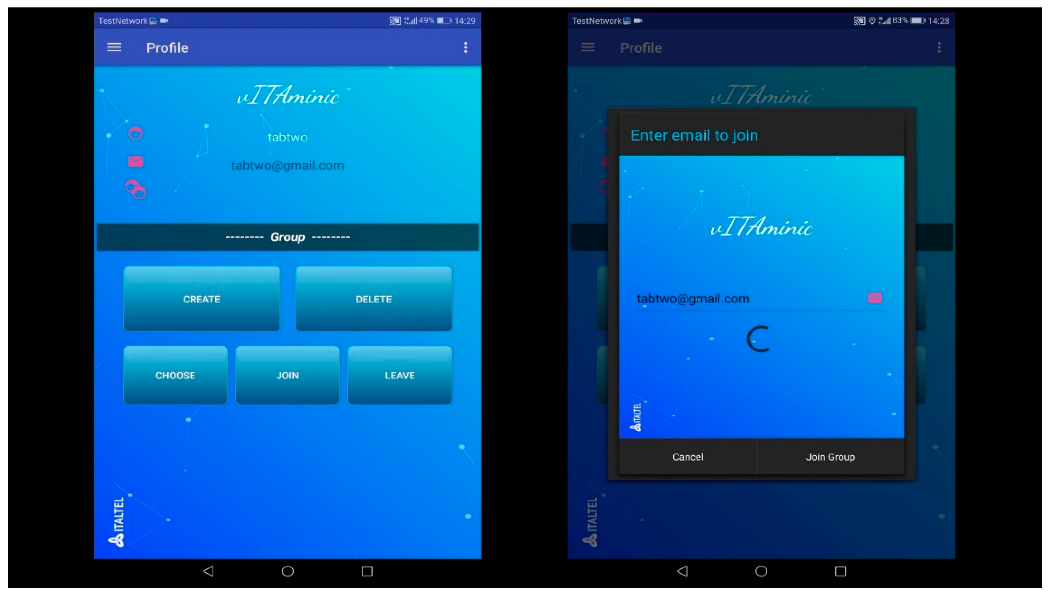
4.2. The i-EVS End-User App
The i-EVS system provides two different interfaces to end users. One is based on web services, and is accessible from any browser; the other is thought to improve QoE, and has been developed as a mobile “app” (the i-EVS end-user app), which can be downloaded by consumers on their Mobile Terminals (two screenshots of the user management interface provided by the end-user app are shown in Figure 9).
All the activities described above, related to the i-EVS ME app, can be accessed through this end-user app: registration, creation of groups, upload/download of contents, and video chatting.
5. Experimental Results
The ME system proposed in this paper has been implemented in a prototypal version running on a real-life testbed, to verify its effectiveness. The testbed, and some experimental results obtained with the i-EVS framework, are presented and briefly discussed in the following sub-sections.
5.1. Testbed Description
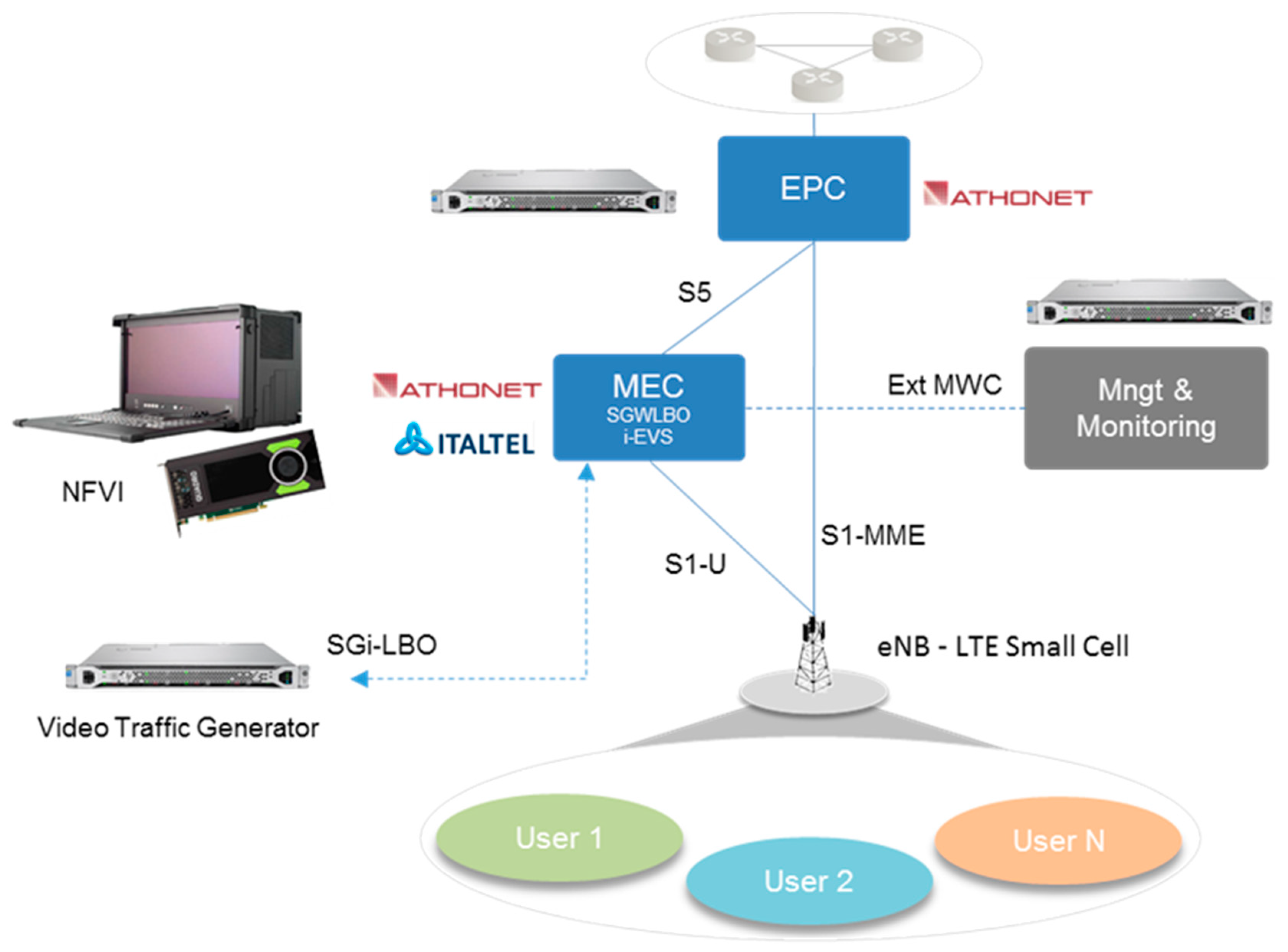
Figure 10 shows a simplified block scheme of the MEC testbed.
The LTE radio interface was implemented using commercial small cells operating in the B40 frequency band (2300–2400 MHz). In the tests, the Huawei tablets MediaPad M3, compatible with such bands, represented the end-user devices, provided with ad hoc pre-programmed SIM cards to register to the testbed radio network [43].
To implement the ME system NFVI, we made use of a portable INTEL-based server (GOMA FlexPAC Industrial portable workstation), of small dimensions to reduce space occupancy (43.4 × 34.8 × 22.9, in cm) and equipped with an Intel Xeon E5-2630v3 2.4 GHz, 8 Core CPU, and 64 GB DDR4 RAM. The GPU-accelerated version of the i-EVS ME app runs on this GOMA server, equipped with one NVIDIA Quadro M4000 GPU.
To realize a complete emulation of an LTE network, an Evolved Packet Core (EPC) running on a physically separated server was also used [43].
In the testbed, a Video Traffic Generator can connect to the SGi-LBO interface of the SGWLBO data plane. In this way, we could simulate loading conditions on the system, both to characterize its performance, and to verify its functionalities under stress conditions.
Connectivity to the management and monitoring functions, running on an external physical system, is provided through the interface indicated as Ext MWC in Figure 10. The management and monitoring block includes the Open Baton orchestrator, combined with the ME functions described in Section 3. Moreover, this block includes Zabbix [44], an open source solution for network and application monitoring.
The testbed creates a physical area in which consumers, through their mobile devices, can access the immersive video services offered by the i-EVS ME app running on the local ME system NFVI.
End users can move in the testbed area creating and sharing media contents using the end-user app.
5.2. Performance Tests
The testbed described makes it possible to verify the behavior of the ME system and i-EVS under stress conditions. To this end, qualitative tests have also been performed during real-life crowded events in which the ME system and i-EVS have been demonstrated.
For example, during a crowded event (the 2018 Mobile Word Congress), we found that uploading a file of a size equal to 100 MB at peak hours can take times of the order of tens of minutes, due to congestion in the backhaul connection to the public Internet. Conversely, the same upload to the local i-EVS eSTORE storage system, accessed through the same radio network, took about 20 s.
A key aspect for a commercial testbed is the computing performance it can achieve. Thus, in the testbed, many loading tests were performed on i-EVS. In particular, the performance of the VTU VNFC has been thoroughly characterized and compared to the one typically achievable in a standard data center using only x86 architectures without HW acceleration.
An example of the performed tests is summarized in Table 1. In this test, parallel transcoding sessions were launched, using video sequences (stored in the local eSTORE storage system) as inputs. The VTU input files were in high-definition format (1920 × 1080 pixel), compressed according to the H.264 coding scheme. For each input video sequence, the VTU VNF provides, as output, four video sequences at different resolutions—namely VGA (480 × 640 pixel), HD480 (480 × 852 pixel), HD720 (720 × 1280 pixel), and HD1080 (1080 × 1920 pixel)—so that users can access video contents at the resolution that best fits their devices. The average time required by the parallel sessions to complete the transcoding process was accurately measured by monitoring the VTU running instance, and by temporally (and artificially) synchronizing the sessions. Since the number of frames of the input video sequences was known a priori, the average transcoding performance expressed in terms of processed frames per second (fps) was easily obtained.
The following table presents some significant results that show the different performance achieved with and without GPU acceleration (with all the available virtual cores of the GOMA server assigned to the VTU). The first column of Table 1 reports the number of concurrent sessions; the second and third columns illustrate the performance in fps with and without GPU, respectively, while the last column shows the acceleration factor achieved, expressed as the ratio of the achieved performance with and without GPU.
The superiority of the GPU-accelerated solution is clear, and is even confirmed when considering energy efficiency, as shown by the experiment summarized in Table 2. In this case, the basic measurement setup was the same as Table 1. Additionally, the power consumption of the GOMA server hosting i-EVS was monitored. To this end, power measurements were carried out in DC, testing the current flowing on the reference voltages of the GOMA server motherboard (12 V, 5 V. 3.3 V). A current clump was used, with a resolution of 0.1 A, resulting in a maximum uncertainty of 1.2 W (on 12 V voltage rail). Table 2 gives the observed transcoding performance expressed in fps, normalized to the measured power consumption in Watt, thus obtaining the efficiency index expressed in fps/Watt reported in the fourth column.
The results obtained can be used as a benchmark dimensioning the ME system at the edge, given the required computing performance, and the constraints in terms of energy consumption and space occupation.
6. Conclusions
This paper has presented an MEC in an NFV integrated environment, on which Mobile Edge applications can run. The proposed architecture can overcome some known management problems typically encountered in the integration of an MEC architecture with an NFV framework.
To demonstrate the capabilities offered by the system, an ME app for CPU-intensive immersive video (named i-EVS) services has been described, combined with a related end-user app.
The virtualization infrastructure hosting the ME apps includes Graphical Processor Units, hence also high CPU-intensive tasks can be performed. Experimental results which show the effectiveness of the proposed solutions have been presented and briefly discussed.
Author Contributions
Conceptualization, G.C., C.M., D.M., F.G. and P.P.; Investigation, G.C. and P.P.; Supervision, P.P.; Writing—original draft, C.M. and P.P.; Writing—review and editing, G.C., C.M., P.P., F.G. and D.M.
Funding
This research was funded by the EU Horizon 2020 5G Essence project (GA No. 761592).
Conflicts of Interest
The authors declare no conflicts of interest.
References
- NGMN: 5G White Paper (2015). Available online: https://www.ngmn.org/uploads/media/NGMN_5G_White_Pa per_V1_0.pdf (accessed on 13 November 2017).
- 5G Infrastructure Public Private Partnership (PPP): The Next Generation of Communication Networks Will Be Made in EU; Digital Agenda for Europe. Technical Report; European Commission: Brussels, Belgium; Luxembourg City, Luxembourg, 2014.
- Blanco, B.; Fajardo, J.O.; Giannoulakis, I.; Kafetzakis, E.; Peng, S.; Pérez-Romero, J.; Trajkovska, I.; Khodashenas, P.S.; Goratti, L.; Paolino, M.; et al. Technology pillars in the architecture of future 5G mobile networks: NFV, MEC and SDN. Comput. Stand. Interfaces 2017, 54, 216–228. [Google Scholar] [CrossRef] [Green Version]
- ETSI White Paper No. 20; Developing Software for Multi-Access Edge Computing. Available online: https://www.etsi.org/images/files/ETSIWhitePapers/etsi_wp20_MEC_SoftwareDevelopment_FINAL.pdf (accessed on 23 October 2018).
- Tanaka, H.; Yoshida, M.; Mori, K.; Takahashi, N. Multi-access Edge Computing: A Survey. J. Inf. Process. 2018, 26, 87–97. [Google Scholar] [CrossRef] [Green Version]
- ETSI GS MEC 001; Mobile Edge Computing (MEC). Available online: https://www.etsi.org/deliver/etsi_gs/MEC/001_099/001/01.01.01_60/gs_MEC001v010101p.pdf (accessed on 23 October 2018).
- ETSI GS MEC 002; Mobile Edge Computing (MEC); Technical Requirements. Available online: https://www.etsi.org/deliver/etsi_gs/MEC/001_099/002/01.01.01_60/gs_MEC002v010101p.pdf (accessed on 23 October 2018).
- ETSI GS MEC 003; Mobile Edge Computing (MEC); Framework and Reference Architecture. Available online: https://www.etsi.org/deliver/etsi_gs/MEC/001_099/003/01.01.01_60/gs_MEC003v010101p.pdf (accessed on 23 October 2018).
- Taleb, T.; Samdanis, K.; Mada, B.; Flinck, H.; Dutta, S.; Sabella, D. On Multi-Access Edge Computing: A Survey of the Emerging 5G Network Edge Cloud Architecture and Orchestration. IEEE Commun. Surv. Tutor. 2017, 19, 1657–1681. [Google Scholar] [CrossRef]
- ETSI GR MEC 017; Mobile Edge Computing (MEC); Deployment of Mobile Edge Computing in an NFV Environment. Available online: https://www.etsi.org/deliver/etsi_gr/MEC/001_099/017/01.01.01_60/gr_MEC017v010101p.pdf (accessed on 23 October 2018).
- Ericsson, Rio-Aiming-Higher-Report, 2016. Available online: https://www.ericsson.com/en/networks/trending/hot-topics/connected-stadium/rio-report (accessed on 25 October 2018).
- Ericsson, Ericsson Mobility Report, 2017. Available online: https://www.ericsson.com/en/mobility-report (accessed on 25 October 2018).
- Frangoudis, P.A.; Yala, L.; Ksentini, A.; Taleb, T. An architecture for on-demand service deployment over a telco CDN. In Proceedings of the IEEE International Conference on Communications, Kuala Lumpur, Malaysia, 23–27 May 2016; pp. 1–6. [Google Scholar]
- Retal, S.; Bagaa, M.; Taleb, T.; Flinck, H. Content delivery network slicing: QoE and cost awareness. In Proceedings of the IEEE International Conference on Communications, Paris, France, 21–25 May 2017. [Google Scholar]
- Li, S.; Guo, Z.; Shou, G.; Hu, Y.; Li, H. QoE analysis of NFV-based mobile edge computing video application. In Proceedings of the 2016 IEEE International Conference on Network Infrastructure and Digital Content (IC-NIDC), Beijing, China, 23–25 September 2016. [Google Scholar]
- Dutta, S.; Taleb, T.; Frangoudis, P.A.; Ksentini, A. On-the-Fly QoE-Aware Transcoding in the Mobile Edge. In Proceedings of the 2016 IEEE Global Communications Conference (GLOBECOM), Washington, DC, USA, 4–8 December 2016; pp. 1–6. [Google Scholar]
- Fesehaye, D.; Gao, Y.; Nahrstedt, K.; Wang, G. Impact of cloudlets on interactive mobile cloud applications. In Proceedings of the IEEE 16th International Enterprise on Enterprise Distributed Object Computing Conference (EDOC), Beijing, China, 10–14 September 2012; pp. 123–132. [Google Scholar]
- Jararweh, Y.; Tawalbeh, L.; Ababneh, F.; Dosari, F. Resource efficient mobile computing using cloudlet infrastructure. In Proceedings of the IEEE 9th International Conference on Mobile Ad-Hoc Sensor Networks (MSN), Dalian, China, 11–13 December 2013; pp. 373–377. [Google Scholar]
- Tran, T.X.; Hajisami, A.; Pandey, P.; Pompili, D. Collaborative Mobile Edge Computing in 5G Networks: New Paradigms, Scenarios, and Challenges. IEEE Commun. Mag. 2017, 55, 54–61. [Google Scholar] [CrossRef] [Green Version]
- Chang, Z.H.; Jong, B.F.; Wong, W.J.; Wong, M.L.D. Distributed Video Transcoding on a Heterogeneous Computing Platform. In Proceedings of the 2016 IEEE Asia Pacific Conference on Circuits and Systems (APCCAS), Jeju, Korea, 25–28 October 2016. [Google Scholar]
- Paglierani, P.; Bliznakov, P.; Paolino, M.; Meani, C. Techniques for providing Software and Hardware Acceleration to VNFs running on the Edge Cloud. In Proceedings of the European Conference on Networks and Communications, Oulu, Finland, 12–15 June 2017. [Google Scholar]
- Comi, P.; Secondo Crosta, P.; Beccari, M.; Paglierani, P.; Grossi, G.; Pedersini, F.; Petrini, A. Hardware-accelerated high-resolution video coding in Virtual Network Functions. In Proceedings of the 2016 European Conference on Networks and Communications (EuCNC), Athens, Greece, 27–30 June 2016; pp. 32–36. [Google Scholar]
- Paglierani, P.; Grossi, G.; Pedersini, F.; Petrini, A. GPU based VP8 encoding: Performance in native and virtualized environments. In Proceedings of the 2016 International Conference on Telecommunications and Multimedia (TEMU), Heraklion, Greece, 25–27 July 2016; pp. 1–5. [Google Scholar]
- Paglierani, P.; Albanese, A.; Meani, C.; Crosta, P.S. Immersive Video Services at the Edge: An Energy-Aware Approach. Int. J. Adv. Telecommun. 2017, 10, 145–154. [Google Scholar]
- Paglierani, P. High Performance Computing and Network Function Virtualization: A major challenge towards network programmability. In Proceedings of the 2015 IEEE International Black Sea Conference on Communications and Networking (BlackSeaCom), Constantia, South Africa, 18–21 May 2015; pp. 137–141. [Google Scholar]
- Available online: https://openbaton.github.io/ (accessed on 25 October 2018).
- ETSI White Paper No. 24: MEC Deployments in 4G and Evolution towards 5G ETSI GS MEC 009: Mobile Edge Computing (MEC); General principles for Mobile Edge Service APIs. Available online: https:// www.etsi.org/technologies-clusters/technologies/multi-access-edge-computing (accessed on 25 October 2018).
- ETSI GS MEC 011: Mobile Edge Computing (MEC); Mobile Edge Platform Application Enablement ETSI GS MEC 010-1: Mobile Edge Computing (MEC); Mobile Edge Management; Part 1: System, Host and Platform Management. Available online: https:/www.etsi.org/technologies-clusters/technologies/multi-access-edge-computing (accessed on 25 October 2018).
- Available online: http://www.etsi.org/technologies-clusters/technologies/nfv (accessed on 25 October 2018).
- ETSI GS MEC 009; Mobile Edge Computing (MEC); General Principles for Mobile Edge Service APIs. Available online: https://www.etsi.org/deliver/etsi_gs/MEC/001_099/009/01.01.01_60/gs_MEC009v010101p.pdf (accessed on 23 October 2018).
- ETSI GS MEC 010-1; Mobile Edge Computing (MEC); Mobile Edge Management; Part 1: System, Host and Platform Management. Available online: https://www.etsi.org/deliver/etsi_gs/MEC/001_099/01001/01.01.01_60/gs_MEC01001v010101p.pdf (accessed on 23 October 2018).
- ETSI GS MEC 010-2; Mobile Edge Computing (MEC); Mobile Edge Management; Part 2: Application Lifecycle, Rules and Requirements Management. Available online: https://www.etsi.org/deliver/etsi_gs/MEC/001_099/01002/01.01.01_60/gs_MEC01002v010101p.pdf (accessed on 23 October 2018).
- ETSI GS NFV-IFA 011; Network Functions Virtualisation (NFV); Management and Orchestration. Available online: https://www.etsi.org/deliver/etsi_gs/NFV-IFA/001_099/011/02.01.01_60/gs_NFV-IFA011v020101p.pdf (accessed on 23 October 2018).
- ETSI GS NFV-SOL 004; Network Functions Virtualisation (NFV) Release 2; Protocols and Data Models; VNF Package Specification. Available online: https://www.etsi.org/deliver/etsi_gs/NFV-SOL/001_099/004/02.04.01_60/gs_NFV-SOL004v020401p.pdf (accessed on 23 October 2018).
- ETSI GS NFV 002 v1.1.1 002; Network Functions Virtualisation (NFV); Architectural Framework. Available online: https://www.etsi.org/deliver/etsi_gs/nfv/001_099/002/01.01.01_60/gs_nfv002v010101p.pdf (accessed on 23 October 2018).
- Carella, G.A.; Pauls, M.; Magedanz, T.; Cilloni, M.; Bellavista, P.; Foschini, L. Prototyping nfv-based multi-access edge computing in 5G ready networks with open baton. In Proceedings of the 2017 IEEE Conference on Network Softwarization (NetSoft), Bologna, Italy, 3–7 July 2017; pp. 1–4. [Google Scholar]
- Sciancalepore, V.; Giust, F.; Samdanis, K.; Yousaf, Z. A double-tier MEC-NFV architecture: Design and optimisation. In Proceedings of the 2016 IEEE Conference on Standards for Communications and Networking (CSCN), Berlin, Germany, 31 October–2 November 2016; pp. 1–6. [Google Scholar]
- Available online: https://www.openstack.org/ (accessed on 25 October 2018).
- Small Cell Forum. Multi-Operator and Neutral Host Small Cell; Version 191.08.02; Small Cell Forum: Dursley, UK, December 2016. [Google Scholar]
- ETSI GS NFV-SOL 005: Network Functions Virtualisation (NFV) Release 2; Protocols and Data Models; RESTful Protocols Specification for the Os-Ma-nfvo Reference Point. Available online: https://www.etsi.org/deliver/etsi_gs/NFV-SOL/001_099/005/02.04.01_60/gs_NFV-SOL005v020401p.pdf (accessed on 23 October 2018).
- ETSI GS NFV-IFA 013: Network Functions Virtualisation (NFV); Management and Orchestration; Os-Ma-Nfvo Reference Point–Interface and Information Model Specification. Available online: https://www.etsi.org/deliver/etsi_gs/NFV-IFA/001_099/013/02.01.01_60/gs_NFV-IFA013v020101p.pdf (accessed on 23 October 2018).
- ETSI TS 129 281. Universal Mobile Telecommunications System (UMTS); LTE; General Packet Radio System (GPRS) Tunneling Protocol User Plane (GTPv1-U) (3GPP TS 29.281 Version 10.2.0 Release 10). Available online: https://www.etsi.org/deliver/etsi_ts/129200_129299/129281/14.01.00_60/ts_129281v140100p.pdf (accessed on 23 October 2018).
- Alcatel Lucent. The LTE Network Tutorial. Available online: http://www.cse.unt.edu/~rdantu/FALL_2013_WIRELESS_NETWORKS/LTE_Alcatel_White_Paper.pdf (accessed on 20 June 2018).
- Available online: https://www.zabbix.com/ (accessed on 25 October 2018).
Figure 1.
ETSI MEC framework reference architecture.

Figure 2.
ETSI NFV reference architectural framework.

Figure 3.
ETSI MEC reference architecture in an NFV environment.

Figure 4.
Overall architecture of the proposed ME system.

Figure 5.
MEC Application Package (MAP) structure.

Figure 6.
OpenStack Dashboard visualization of the network services, including SGWLBO and i-EVS.

Figure 7.
Data plane architecture based on Local Break Out at SGW.

Figure 8.
The i-EVS VNF architecture.

Figure 9.
Screen shots of the i-EVS end-user app, showing the user management interface.

Figure 10.
Simplified block scheme of the implemented MEC testbed.


Table 1.
Transcoding performance of i-EVS with and without GPU.
| Transcoding Sessions | SW-Only Transcoding Performance (fps) | GPU-Accelerated Transcoding Performance (fps) | Performance Improvement Using GPU |
|---|---|---|---|
| 1 | 60.2 | 205 | 3.4× |
| 2 | 32.6 | 186.2 | 5.8× |
| 4 | 16.3 | 97.8 | 6× |
| 8 | 8.7 | 49.5 | 5.7× |
| 16 | 4.3 | 24.75 | 5.7× |
Table 2.
Transcoding efficiency of i-EVS with and without GPU.
| Transcoding Sessions | SW-Only Efficiency (fps/Watt) | GPU-Accelerated Efficiency (fps/Watt) | Efficiency Improvement Using GPU |
|---|---|---|---|
| 1 | 0.50 | 2.16 | 4× |
| 2 | 0.55 | 3.21 | 5.8× |
| 4 | 0.55 | 3.29 | 6× |
| 8 | 0.58 | 3.27 | 5.6× |
| 16 | 0.58 | 3.14 | 5.4× |
© 2018 by the authors. Licensee MDPI, Basel, Switzerland. This article is an open access article distributed under the terms and conditions of the Creative Commons Attribution (CC BY) license (http://creativecommons.org/licenses/by/4.0/).
Share and Cite
MDPI and ACS Style
Cattaneo, G.; Giust, F.; Meani, C.; Munaretto, D.; Paglierani, P. Deploying CPU-Intensive Applications on MEC in NFV Systems: The Immersive Video Use Case. Computers 2018, 7, 55. https://0-doi-org.brum.beds.ac.uk/10.3390/computers7040055
AMA Style
Cattaneo G, Giust F, Meani C, Munaretto D, Paglierani P. Deploying CPU-Intensive Applications on MEC in NFV Systems: The Immersive Video Use Case. Computers. 2018; 7(4):55. https://0-doi-org.brum.beds.ac.uk/10.3390/computers7040055
Chicago/Turabian StyleCattaneo, Giorgio, Fabio Giust, Claudio Meani, Daniele Munaretto, and Pietro Paglierani. 2018. "Deploying CPU-Intensive Applications on MEC in NFV Systems: The Immersive Video Use Case" Computers 7, no. 4: 55. https://0-doi-org.brum.beds.ac.uk/10.3390/computers7040055
Note that from the first issue of 2016, this journal uses article numbers instead of page numbers. See further details here.