1. Introduction
Traditional static single camera vision configurations are bounded to perceive only one perspective of a scene. In contrast, there is the field of active vision, in which cameras are dynamically manipulated to manage input vision data. We are specifically interested in incorporating active vision techniques to manage cameras mounted on autonomous robots to enable them to better understand and explore their surroundings, compared to the traditional static camera solutions. In general, such techniques are well suited for (1) detecting and avoiding occlusion by direct camera manipulation, (2) achieving a dynamic, wide field of view for tracking, and (3) recognizing objects of interest, human postures, and gestures at finer levels of camera resolution. Here, by extending our previous work [
1], we aim to improve the detection performance of objects by trying to avoid occlusions and fetching input vision data from dissimilar viewpoints of objects and in different distances of objects to the cameras.
Modern robotic systems typically comprise numerous sensors, including depth and ordinary RGB cameras. The availability of more than one camera allows processing various points of view for individual objects. Nevertheless, this opportunity is not equal to exhaustively process all the possible viewpoints, as it is not an efficient method considering the large amount of time, energy, and computational resources necessary to fulfill that. Even if all the available cameras are fixed to continuously capture many views of the scene, it is still not a practical strategy, since it would increase the computational burden on the system, to the point where real-time functionality becomes difficult to achieve. Sensor management addresses this issue, while utilizing the availability of multiple cameras in a robotic setup. By dynamically selecting the most appropriate information from the cameras and deciding on their pose, this kind of sensor management, which we employed in a robotic platform for the task of object detection, belongs to the family of active vision methods.
An active vision system is presented in [
2] that is able to dynamically decide how it can make the best use of information from a few stationary cameras. An active object recognition system is proposed in [
3], which makes use of saccades, i.e., small camera movements, to provide more useful information from a dynamic vision sensor (DVS) for the object recognition task. The saccadic motions are determined by a trained artificial neural network. A leader–follower robotic setting with the ability of actively tracking the leader is implemented in [
4] through dynamically rotating a pan-controlled camera. In another work [
5], a reinforcement learning approach in a vision system is proposed for selectively focusing on parts of the input image. In that work, the processing speed and learning rate were improved as a result of the active selective attention mechanism. An attention selection technique for event recognition is also presented in [
6]. An active object detection and pose estimation method with dynamic camera location planning is presented in [
7]. The sensor used was an Asus Xtion RGB-D camera mounted on the PR2 robot’s wrist. This method tries to balance the amount of energy needed to move the camera and the added chance of getting a better object detection. In another work [
8], an active vision system is employed on a quadrotor to detect gaps. As the quadrotor moves, optical flow is computed by considering different captures of the same scene. Subsequently, contours of the gaps are detected from the resulting optical flow. Some systems to select the next best view are also proposed for scene modeling [
9] and object recognition [
10]. The work of [
11] performs the selection of next best view based on the estimation of information gained from different views. For further reading about the active vision methods and a survey of their literature, refer to [
12].
In this work, an active object detection system to utilize two cameras on a PR2 robot is proposed. Although it is implemented on a PR2 robot, the proposed vision system is applicable to any similar robotic platforms. The first camera to use the proposed vision system is a 3D Kinect v1 sensor (main camera) mounted on the robot’s head. The other one is an RGB camera (secondary camera) existing on the robot’s left arm. The first step in the proposed vision system is to detect the object viewed by the main camera and compute a confidence measure for it. Considering the confidence value of each detection, the system decides if they are reliable or not. In the case of an unreliable detection, detection results from the secondary camera are requested after the pose of the secondary camera is adjusted by moving the left arm toward the object that corresponds to the unreliable detection. Then, the resultant detections from the two camera views are matched and later combined through a novel transferable belief model, which is a variant of the Dempster–Shafer evidence theory. With the final detection results obtained, the system attains the 3D positions of each object with respect to the robot, and sends them as well as the labels to other nodes in the robotic arrangement to use them accordingly.
The contributions of the proposed method are (1) a dynamic assignment of a second camera by switching to process its data to detect objects in an eye-in-hand system implemented on the PR2 robot, (2) a distance-based object matching with the efficient use of available information in the robotic platform, and (3) fusing the classification decisions with a novel Dempster–Shafer fusion technique.
In contrast to our previous work [
1], the functionality to dynamically move the camera on the robot’s arm toward objects is added to the current approach. In the earlier work, the camera was stationary, but now it computes the 3D location of objects and moves toward them to get a better viewpoint of objects. In addition, the detection algorithm is changed in the proposed method. In the earlier version, it was based on background subtraction, but in its current state, it is a sliding window detection system. Moving away from background subtraction was necessary, as it was not compatible with moving cameras. In order to address the added computational cost of the new detection system, a tracker is added to the method, compared to that in [
1]. The object tracker enhances the running speed of the proposed method to keep it suitable for real-time applications.
In the rest of this paper, the proposed active vision system is described in
Section 2. Experimental results are presented in
Section 3, followed by a discussion and analysis of results in
Section 4. Finally, concluding remarks are provided in
Section 5.
2. The Proposed Active Object Detection System
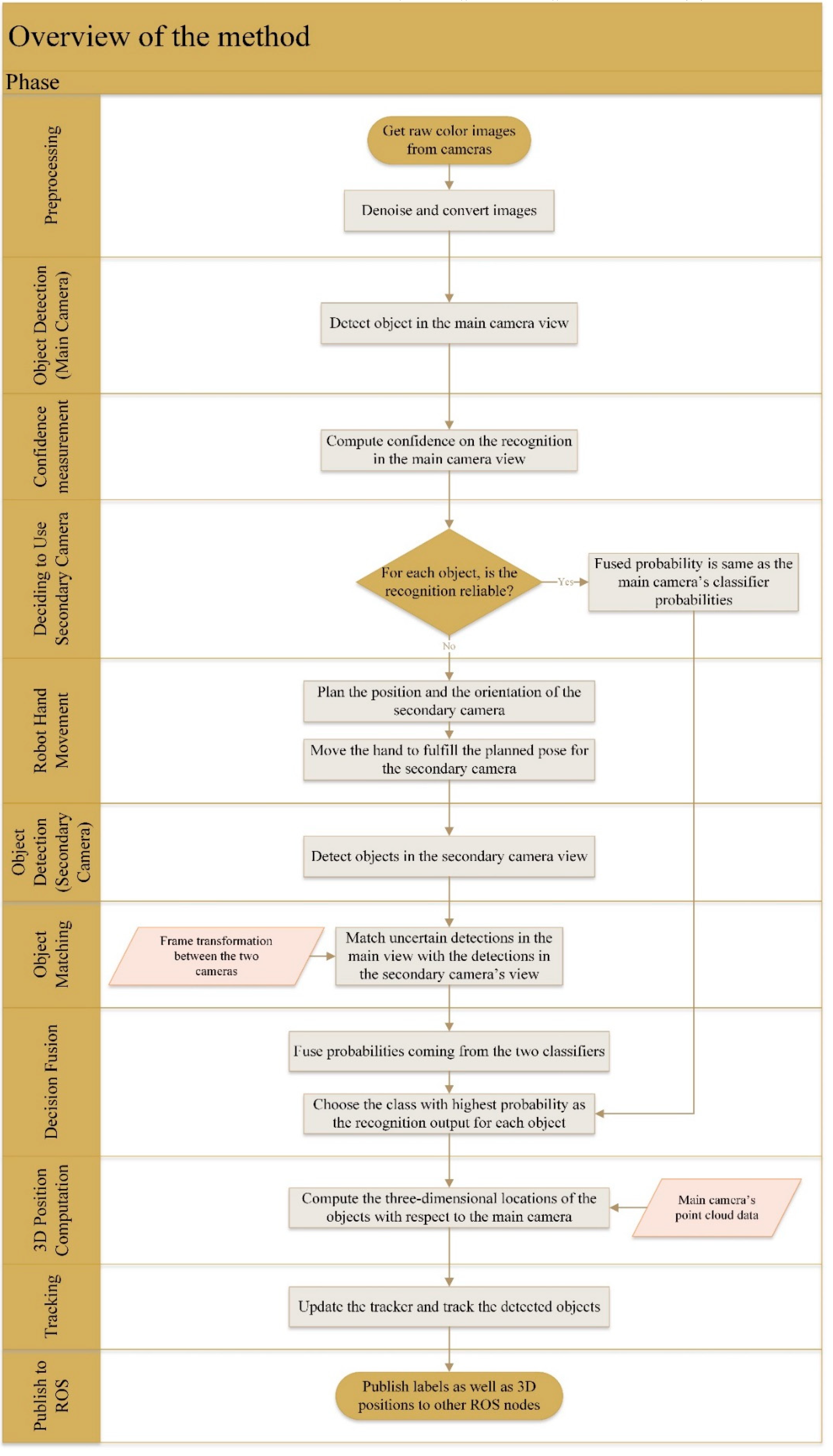
The general steps in the proposed method are depicted in the flowchart of
Figure 1, with the left vertical bar showing the main phases. In the beginning, input frames are processed with a median filter to eliminate impulsive noise. Next, potential objects of interest in the scene viewed by the main camera are detected by using a sliding window mechanism. We used the sliding window-based detection as a simple and yet effective method in our case.
For each of the candidate objects, a feature vector based on a histogram of oriented gradients (HOG) [
13] and a color histogram is extracted. HOG is responsible for capturing the edge-based appearance, while the color histogram is generated by merging two flattened 2D histograms for the HSV (i.e., Hue, Saturation, Value) and CIELUV [
14] color spaces. The 2D histogram of the HSV color space is only dependent on the hue and saturation channels, while the 2D histogram of the CIELUV color space is obtained from the
u and
v channels. These channels encode the color information of the pixels. In contrast, the two discarded channels, value (V) and lightness (L), contain the brightness information.
After extracting the features, the number of HOG features is reduced through the principal component analysis (PCA) method to ensure that the subsequent classifier sees a moderate number of features, given the number of available training samples. In other words, it prevents the curse of dimensionality.
A non-linear multi-class support vector machine (SVM) classifier with a radial basis function kernel and one-versus-rest strategy is used in our method to classify the input features. By adopting a fairly standard optimization-based method [
15] for classification, here, we emphasize more the performance enhancement of the detection system via the active utilization of the eye-in-hand data rather than the behavior of an individual classifier. As will be discussed later, the proposed decision fusion method, based on the Dempster–Shafer theory, is a non-singleton probability-based fusion technique that transforms the classification problem at hand to a multi-label classification. To realize a multi-label classifier, the well-known binary relevance [
16] method is employed, for which a one-versus-rest SVM classifier can be a plausible implementation approach. The classifier outputs mass values for each trained object class in relation to the Dempster–Shafer decision fusion approach mentioned earlier. It will be explained later that mass values stand as counterparts of probabilities in terms of the Dempster–Shafer theory, and exhibit belief of the classifier regarding the similarity to object classes.
By obtaining mass values for each trained object class, a confidence measure is calculated through dividing the maximum mass value of all object classes by the second-largest mass value. In this way, the confidence metric looks for large enough peaks in the array of mass values. A low confidence normally translates to two close competitor object classes, which makes selecting either of them error-prone for object recognition. Consequently, if the confidence is greater than a threshold value, it is considered reliable, and the category with the largest mass value is selected as the recognition result. Otherwise, the active vision system will dynamically request additional evidence from the secondary camera in order to improve the reliability of the detection process.
To this end, if the detection of an object in the main view is uncertain, the robot’s hand with the secondary camera mounted on it moves toward the object to get a different viewpoint of the object. Before the actual movement, the position and orientation of the secondary camera should be determined to get a clear and close enough view of the object. The pose planner of the secondary camera in our work considers the relative location of object with respect to the left arm’s shoulder joint of the PR2 robot; by assuming that as an edge of a triangle, with the other two edges being the upper arm and the distance from elbow to the object, it plans the pose accordingly.
After the hand motion is done, objects in the secondary camera’s sight are detected and matched with earlier detected objects from the viewpoint of the main camera. Matching is indispensable for the fusion of the classification decisions, since it is necessary to know which detection results should be fused together. The Euclidean distance-based matching procedure is discussed in the next section, followed by a description of the decision fusion technique. The latter is a novel variation of a transferable belief model, which in turn is a type of Dempster–Shafer fusion method. In the case where no object in the secondary view can be matched to an unreliable detection in the main view, there would be no fusion, and the initial detection is considered final. The fusion component of the proposed method outputs a probability vector after fusing masses from the two classifiers. With the probabilities of object categories obtained after the fusion, the category with the highest probability is chosen as the winner class to determine the final object labels.
In the next three subsections, we detail the pose planner and object matching approaches as well as the decision fusion technique.
2.1. The Pose Planner
Whenever there is an unreliable detection, the secondary camera should be planned to be moved to a proper pose to have a clear view of the object. Unlike the works [
9,
10,
11], the proposed pose planning method is not designed for a mobile robot. Instead, we are assuming that the robot only moves its arm and the camera mounted on it to get a new viewpoint of an object. On the other hand, to compute the arm camera pose, our method, in contrast to the analytical methods of [
9,
10,
11], is solely dependent on the deterministic computation of robot arm joints through geometric triangulation. Our strategy to determine the joint angles of the robot arm is to have a side view of objects with the secondary camera that is almost orthogonal to the primary view.
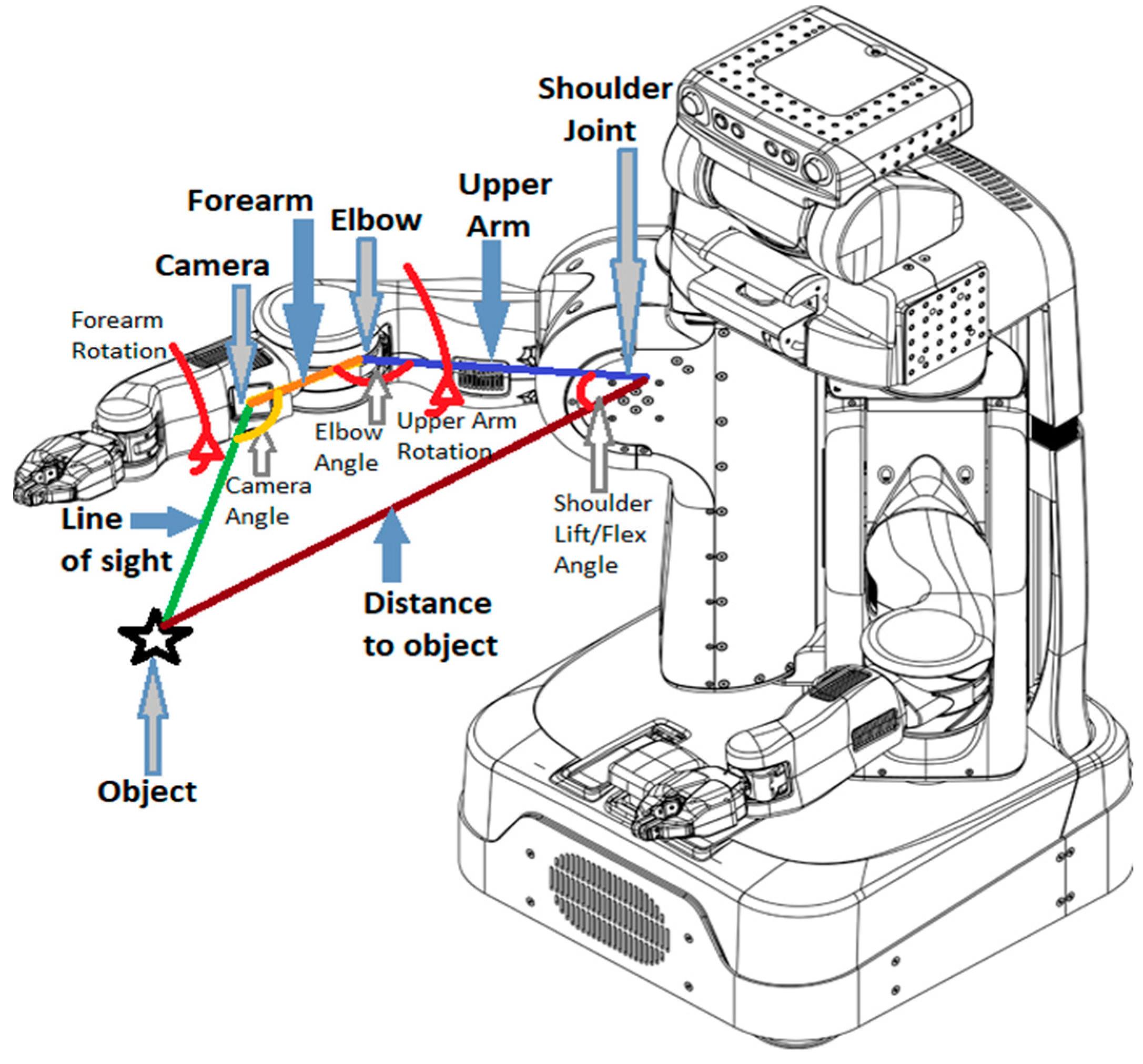
Figure 2 shows a schematic of the PR2 robot, in which the main parameters for planning the robot’s arm are shown in red. The distance of the object to the shoulder joint is computed by using the point cloud data from the 3D camera and the robot’s inner frame transformations. The camera angle, forearm length, and upper arm length are also known in advance. Through the geometric computations, it is possible to find the shoulder lift and flex joints to have the secondary camera pointed toward the object. The forearm roll (rotation) is determined relative to the computed shoulder joint value to keep the forearm camera (secondary camera) facing the object. The elbow flex angle and the upper arm rotation are set to a fixed value to simplify calculations by reducing the number of degrees of freedom in the planner.
2.2. The Object-Matching Module
It was mentioned before that matching is indispensable for the proper functionality of the active vision system before any decision fusion is performed. Various methods can be considered for matching objects, such as those based on appearance, keypoint, and shape [
17]. However, they would probably encounter problems in working with two very different viewpoints on objects, as we have in our case. In our method, the head and the arm camera are desired to present unalike views of objects to complement each other, which are unfavorable for the aforementioned matching techniques. Instead, we can precisely compute the transformation of an object position in the pixel coordinate of the main camera to the pixel coordinate of the secondary camera by utilizing the available 3D information from the 3D camera, the transformation between the two camera coordinates, and the intrinsic calibration data of both cameras. This transformation makes it possible to calculate the distance of objects in the pixel coordinate of the secondary camera and match them accordingly. This approach is possibly faster than appearance, shape, and keypoint matchings, as there is no feature extraction or correlation computing involved. Although the proposed object matching method is dependent on transforming the coordinate of one camera to the other one, it is not equivalent to pixel correspondence, which is common in stereo vision. Here, our task is to match objects in the two views, instead of matching two pixels.
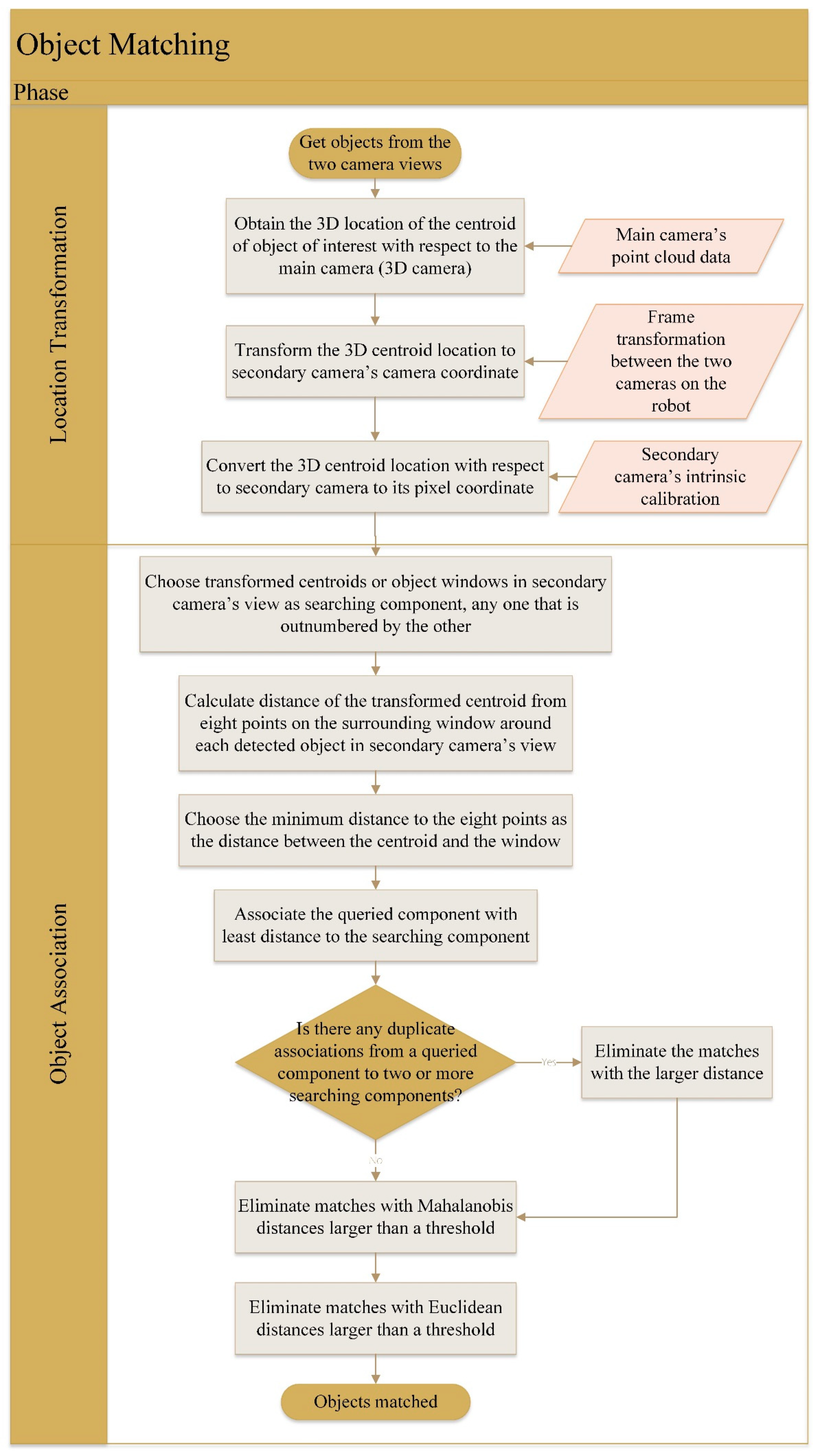
The flowchart of the proposed matching method is displayed in
Figure 3. For any object in the main view to be transferred to the secondary view, we initially compute its centroid. Then, the centroid position in the pixel coordinate of the main camera is converted to the 3D location in the camera coordinate of the main camera. Knowing the transformation between the two camera frames, the object position is transformed to the camera coordinate of the secondary camera. Subsequently, the object location is converted to the pixel coordinate of the secondary camera using the intrinsic calibration information of the camera. The transformation of the centroid of the object to the other camera view assumes that the centroid falls upon the object surface. Nonetheless, it speeds up the matching of objects by just converting the reference frame of a point in the world, as well as by avoiding feature extraction and correlation computations.
With all the detections in the main camera transformed to the secondary camera view, there would be two groups of components to match: namely, the transformed centroids of the main view’s objects, and the bounding boxes of the detections in the secondary view itself. The larger group (with more components) is chosen as the one being queried in the distance matching, while the other group is the searching group. In order to compute the distance of each centroid from each bounding box, we consider the minimum of distances of the transformed centroids from eight points around the bounding boxes: four corners and four middle points on each edge of a bounding box. The selected distance metric is the L2 distance. By getting the least distance to eight points around a bounding box, we try to prevent problems in matching objects that appear long in the secondary view. For those kinds of objects, the viewable surface from the point of view of the main camera, and thus its centroid, may be far from the centroid of the object in the secondary view, causing difficulties for the distance matching to associate proper components. In contrary, by considering eight points located around the bounding box, there is a high possibility that there would be at least one association with a close distance.
In the proposed method, any matching is established by associating a searching component with a queried component with which it has the least distance. However, for a queried component, there can be multiple associations to several searching components. This issue is remedied by simply keeping the match with the smallest distance. Following that, matches with Mahalanobis distances of more than a threshold are discarded to eliminate any matches with irregular distances compared to all the others. In addition, associations with Euclidean distances of more than a predefined threshold are canceled to avoid matches with very large absolute distances.
2.3. The Dempster–Shafer Decision Fusion Module
The Dempster–Shafer evidence theory (DST) [
18] is an information fusion method that takes into account inaccuracy and uncertainty [
19]. In contrast to Bayesian fusion, DST does not only work with singleton probabilities. Instead, it introduces alternative units of belief with non-empty intersections [
20]. Some examples of application of the Dempster–Shafer fusion are airborne object identification [
21], human activity recognition [
22], and vehicle location verification [
23].
Assume there is a set of singleton probabilities
Ω, which is named the ‘frame of discernment’. By singleton, we mean that the probabilities in
Ω are mutually exclusive. In a classification task, the frame of discernment represents the set of object categories. Dempster–Shafer fusion makes allowances for the power set of
Ω, instead of merely relying upon singleton probabilities. The power set of
Ω includes all combinations of singleton probabilities from the set universe of
Ω to an empty set. In the framework of Dempster–Shafer fusion, any element of the power set is assigned a value in the range of [0, 1], which is termed mass. Any element of the power set of
Ω with a mass value greater than zero is called a ‘focal element’. Based on the above definition, we may think of masses in DST fusion as a counterpart of probabilities in Bayesian fusion. Similar to probabilities, the sum of all masses must be equal to 1, as shown in Equation (1). In the equation,
represents a member of the power set (i.e., a subset) of
Ω, while
m(.) is a mass value for it:
In our method, frame of discernment stands for the probability vector coming from each classifier. Hence, there are two frames of discernment for the two classifiers. Given n object classes, each probability vector—or in other words, every frame of discernment—will contain those n elements. In addition to the n elements of the frame of discernment, each classifier output also has an additional focal element: that, is the “universal” element. The universal element is the universe of the object categories. By defining the mass values for the members of the power set this way, there would be a mass value for every object class. Moreover, the mass of the extra universal element indicates the similarity of the object of interest to the entire training set. Therefore, the mass of the universal element is equivalent to the probability of a “universal” object, because it does not distinguish any specific category.
In the case of the proposed Dempster–Shafer fusion, we need to have n + 1 output classes in each classifier to get n + 1 masses. Out of them, n object categories are trained similar to standard training routines. However, the “universal” class is trained with a training set made of half of the training images of each object category combined. The reason to use only half of the training set is that it decreases the training time substantially. To counter the effect of a class with larger training samples than others during the training, the optimization formulae of the SVM classifier is weighted relative to the training set size of each object category.
By adding a universal class, each sample during the training time will have two correct labels: the original object category and the added universal class. This means that the proposed classification task falls under the category of multi-label classification methods. Since a one-versus-rest strategy is used for the support vector machine, during the training, we will have a training strategy similar to the binary relevance method [
16], which is an established method in the multi-label classification domain.
To fuse the output mass values of the two classifiers, the unnormalized rule of combination is utilized, which makes the proposed fusion method an instance of the transferable belief model [
24]: a variant of the Dempster–Shafer fusion. The unnormalized rule of combination for our dual-classifier fusion case is presented in Equation (2):
where sets
A and
B are the set of mass values resulted from the classifiers for the main view and the secondary view, respectively. The term
represents the mass of category
. Elements
α and
β are each an object category in the set of mass values of the main view and the secondary view classifiers, respectively. Considering the above descriptions, a category
α in the mass vector of the main view (
A), except for the class “universal”, has intersection with two
βs in the mass vector
B. The first one is the same category as
α in
B, and the second one is the “universal” category. The same is true for an output element of the second classifier (
β).
In order to convert the mass values back to the probability domain, we use the pignistic transformation explained in [
25], as shown in Equation (3):
where
is any focal element of the power set of object categories that has the object class
as an element, and
designates the number of object classes in
. Furthermore,
is the probability of an object category
ω, excluding the “universal” class. Equation (3) conveys that the belief in any focal element is dispersed among its constituting class probabilities. Finally, after performing the conversion of Equation (3) and obtaining the probability values, they are normalized to sum to one.
As stated earlier, besides the actual object categories present in the training, the two classifiers supply a mass value for a “universal” class. The “universal” category is a tool for a classifier to indicate its uncertainty in detecting an object. From Equation (1), we know that the sum of all masses in an output mass vector is equal to 1; thus, an increase in the mass of the universal category causes the other classes in the same mass vector to take a lower share of mass values. In addition, from Equation (2), we observe that a rise in the mass of the universal category of a classifier not only reduces the rest of the masses of that classifier, but also it weighs more toward the masses of the other classifier, with which it has a non-empty intersection, through multiplying. In the contrary, when the mass of the universal category of a classifier is low, it designates a resolute classifier that contributes more to the final decision fusion result [
26].
3. Experimental Results
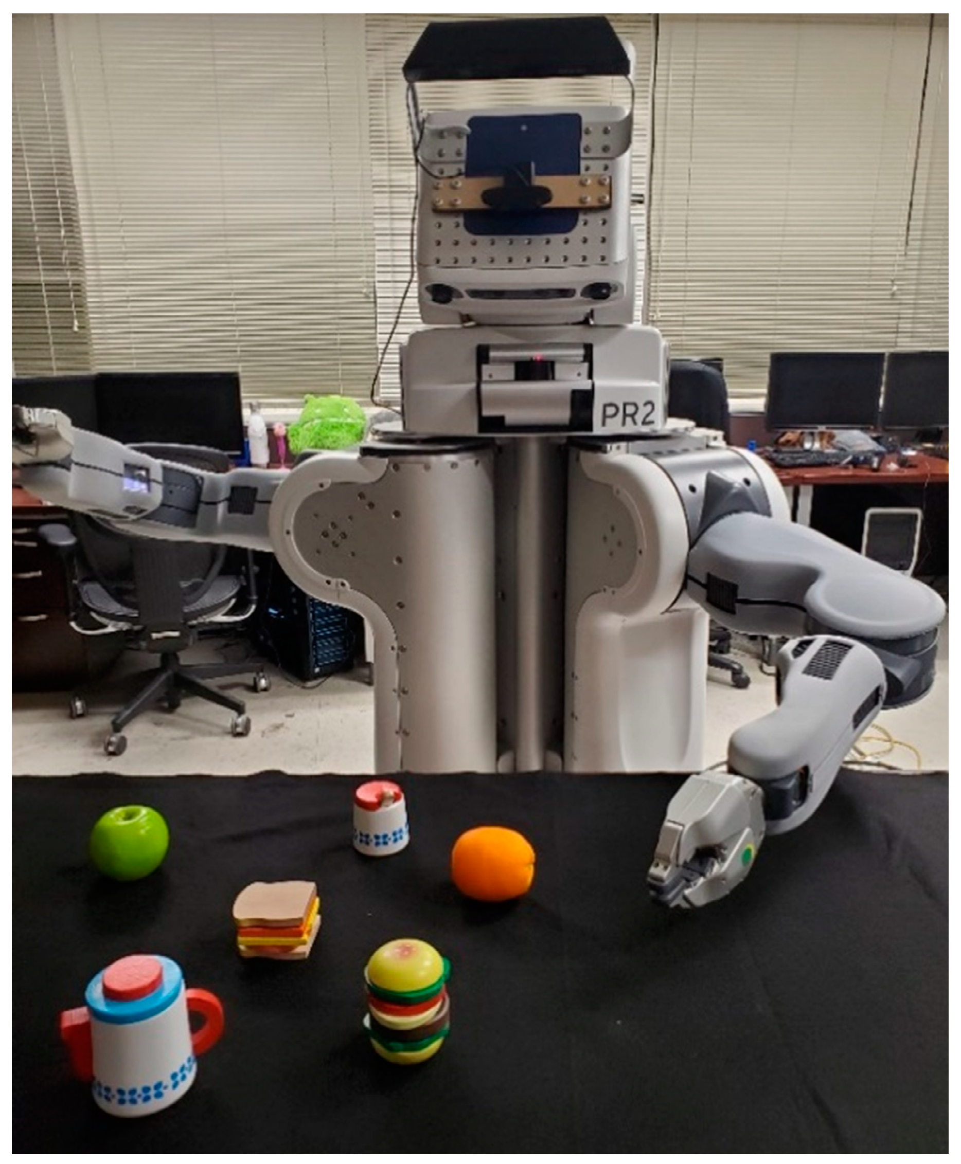
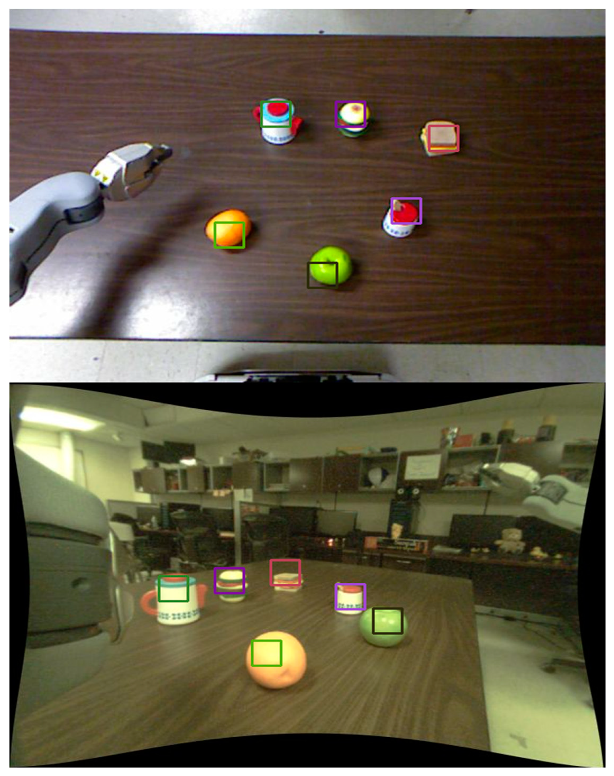
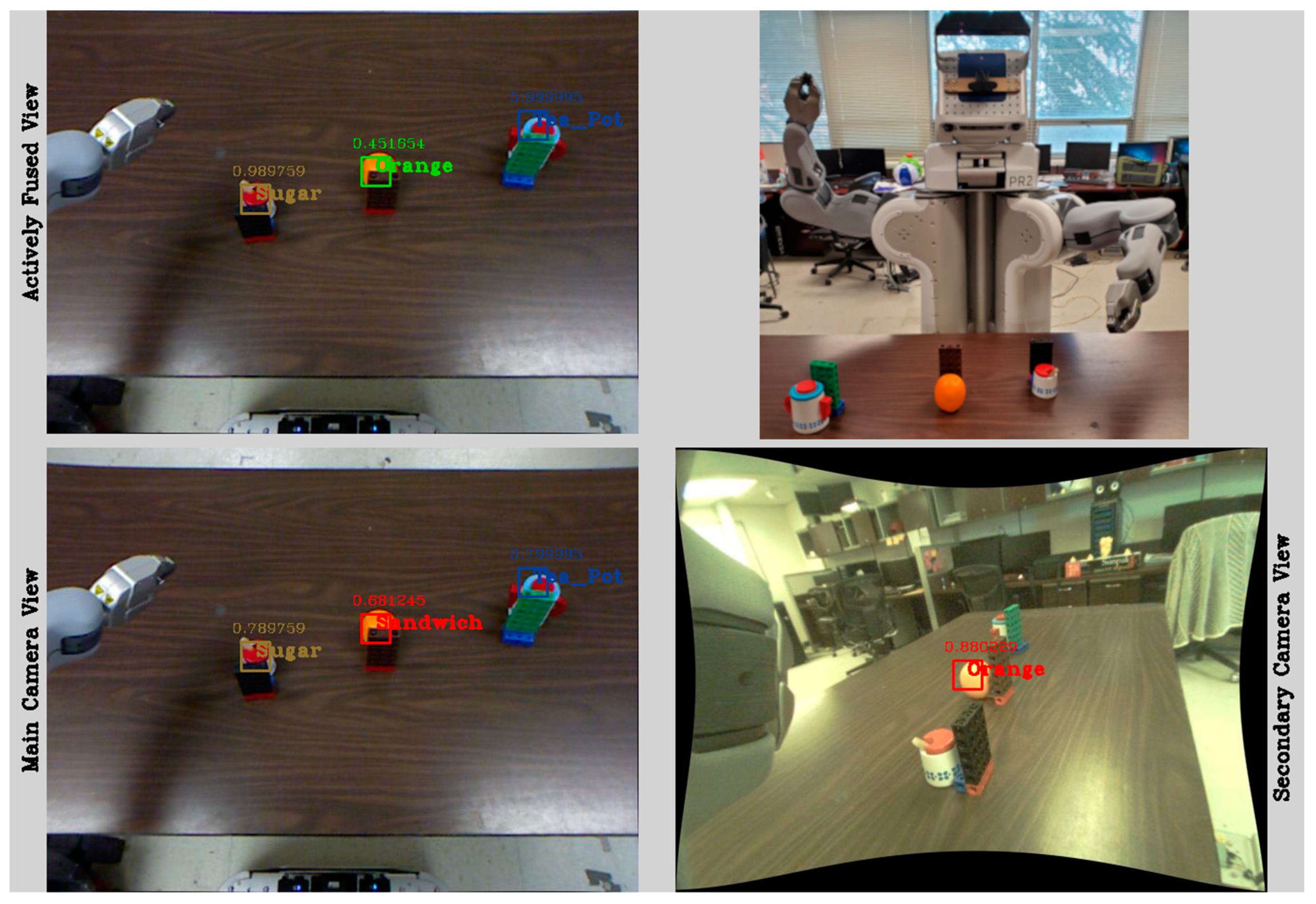
The results obtained in 15 real-world benchmarks are presented in this section. The proposed active vision system was realized on a PR2 robot and was verified in different lighting conditions and object placement settings. In all the experiments, objects were placed on a table in front of the robot in various locations. An example of the robot gesture in one of the trials is shown in
Figure 4.
Figure 4 also shows the six objects used in our experiments. The objects were selected to have at least one other similar object in the tests. The classifier was trained with a dataset comprised of augmented data obtained from around 30 original training images per object category. The number of features extracted from each image is 50 color features and 60 HOG features after reduction via PCA. During the training of the classifier, we employed a four-fold cross-validation technique and a grid search to find the optimal SVM parameters.
Initially, we evaluated the proposed matching algorithm in 180 object association test instances.
Figure 5 shows a few object matchings between the main and the secondary views. In the figure, detections with the same color are matched together. As it can be seen, the matchings of objects are all correct in
Figure 5. In the real-world experiments, 95% of the matchings were correct. Since the matching happens in the pixel coordinate of the secondary view, object mismatches happen for objects—mostly close ones—in that view.
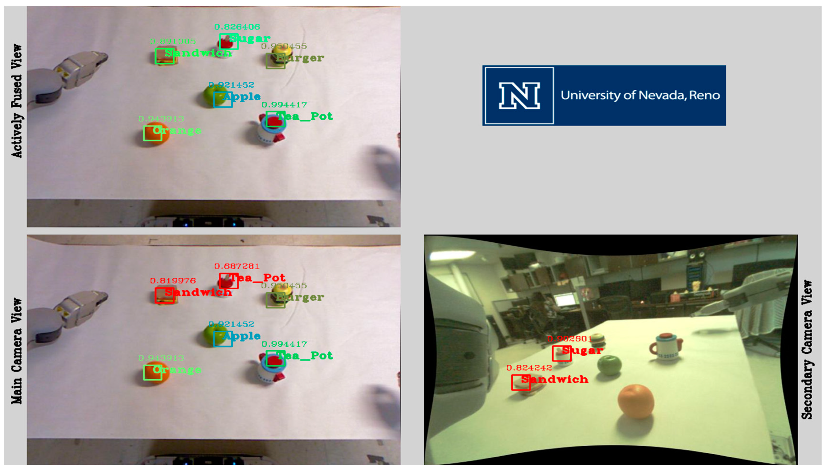
Figure 6 displays a sample output of the system. In the figure, there are three mistakes in the detections of the bottom left window (main view): Tape Measure and Tea Pot are wrongly classified as Burger, and Sugar is incorrectly labeled as Tea Can. Those three objects besides two other detections have their bounding boxes in red, which signal unreliable classifications. The bottom right window of the figure (secondary view) illustrates the detected objects in the secondary camera’s input frame, for which there is a match found with the unreliable detections in the main view. After fusing the classifications, the final detection results in the top left window of
Figure 6 are all accurate.
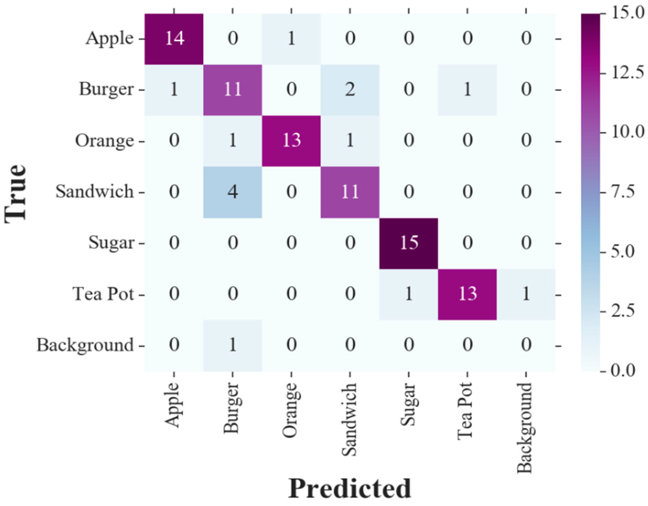
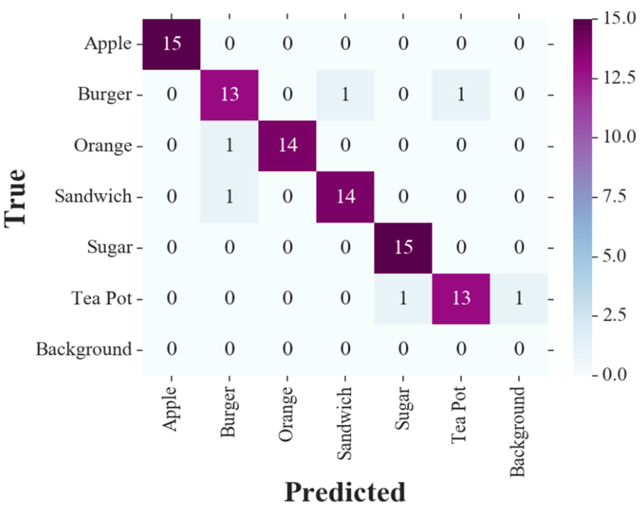
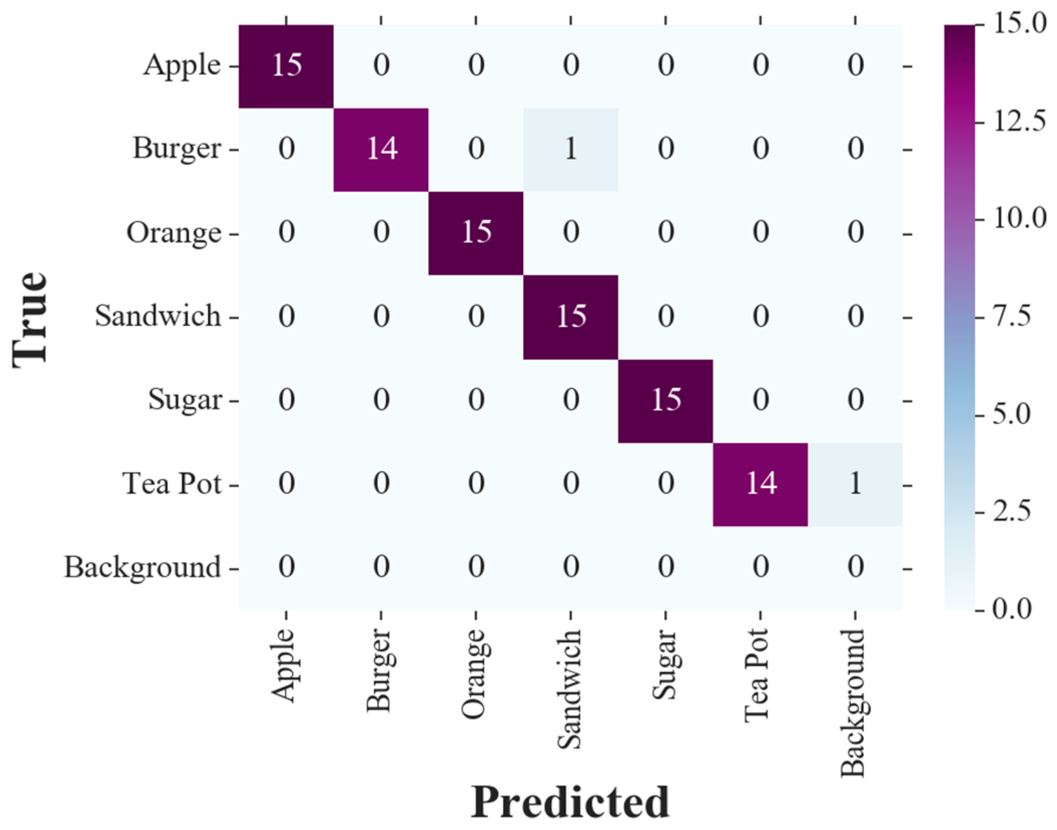
The confusion matrix resulted from our tests with six nonoccluded objects, for the main view only detections is shown in
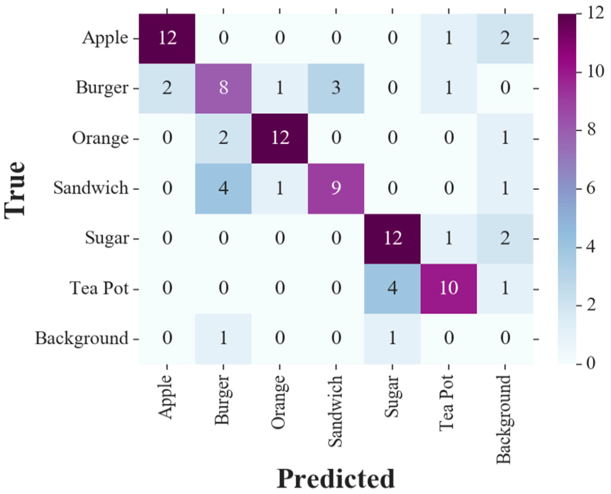
Figure 7. The confusion matrices with the proposed active vision system for the same tests are displayed in
Figure 8 and
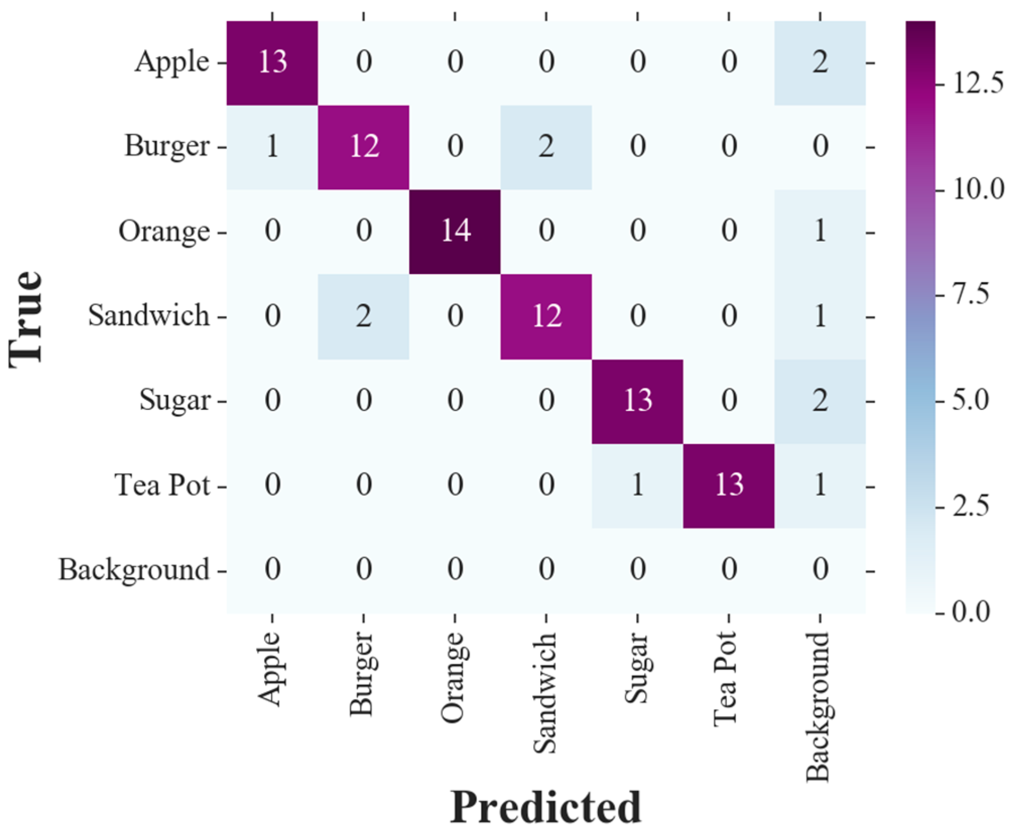
Figure 9. The results shown in
Figure 8 are for the proposed system without any arm movements toward the objects. Instead, the secondary camera was fixed in different prespecified poses during the tests. Despite the setting of the secondary camera not moving, the test objects were still observable to the secondary camera (i.e., in the field of view of the camera) in all the experiments to keep comparisons with the proposed system with dynamic camera movement fair. On the other hand,
Figure 9 demonstrates the confusion matrix obtained with the full functionality of the proposed vision system, including dynamic arm planning toward the object. In the confusion matrices, the Background column indicates target objects not detected at all, and the Background row counts any undefined entity being falsely detected as a target object. The intersection of the Background row and column is also intuitively void.
Four performance metrics for object detection were calculated using the confusion matrices: namely, accuracy, recall, precision, and F
1 score. Precision is the number of true positives over the total number of positives. It measures how well the classifier distinguishes true objects of interest from false positives. Recall is defined as the ratio of true positives over ground truth positives, and is used to assess the capability of the classifier in finding objects of interest. To balance these two metrics, the F
1 score takes the harmonic mean of precision and recall. On the other hand, accuracy is obtained by dividing the number of true detections to the total number of the observed detections in the test. It evaluates the ability of the classifier to correctly perform the recognition task.
Table 1 illustrates the computed performance metrics for the three test cases: single camera, active vision without camera movement, and active vision with camera movement. The macro-averaging in
Table 1 implies that the measure is computed separately for each object class, and later is averaged over them. In contrast, in micro-averaging, the measures are calculated for all the object classes collectively. Micro-averaging results are not included in
Table 1, since micro-averaging recall and precision are equivalent to accuracy in a multi-class classifier.
Table 1 shows large improvements in all four measures compared to the traditional single camera setup. The proposed active vision system achieved 12.9%, 12.2%, 13.1%, and 12.5% increases in precision, recall, accuracy, and F
1 score, respectively. This enhancement in performance brings up the accuracy of the experiments to 97.7%. Other metrics are also over 97%. By comparing the performance metrics of the proposed method with its variation with non-moving cameras, we realize that dynamically moving the secondary camera toward the objects with uncertain detections improves the measures by at least 4.4%. This proves that not only using cameras in different viewpoints contributes to a better detection performance, but also planning and moving the extra views help further improvements.
We also evaluated the proposed system’s ability to cope with partial occlusions by testing it against benchmarks with objects being intentionally occluded. In the experiments, objects were partially occluded by placing a barrier in front of the objects to partly block their visibility from the viewpoint of the main camera. However, in spite of aiming to have occlusions in the main view, there could be test situations in which the objects in the secondary viewpoint are also occluded partly by the barriers or the other objects on the table. Although there was a mixture of occluded and non-occluded objects in the table-top settings in our tests, the results for occlusion tests are only obtained from the occluded objects in the test scene. A sample test situation with three partially occluded objects in the scene is demonstrated in
Figure 10. It is observed in
Figure 10 that one of the partially occluded objects is classified incorrectly in the main view (as a Sandwich), but after checking the confidence, detecting objects in the secondary view, matching the uncertain detection with its corresponding one in the secondary view, and finally by fusing the classification decisions, the final result in the top left sub-image is correct (i.e., detected as an Orange).
Figure 11 shows the confusion matrix of the single camera setup, whereas
Figure 12 and
Figure 13 illustrate the confusion matrices resulted from utilizing the proposed system in cases of stationary and moving cameras, respectively.
Table 2 illustrates the computed metrics for this test benchmark, showing the advantage of the proposed method in dealing with partial occlusions from the viewpoint of the main camera. It is observed that the proposed method alleviates the adverse effect of partial occlusions. Compared to the single-camera configuration, precision, recall, F
1 score, and accuracy are respectively 18.3%, 15.5%, 16.9%, and 17.1% more with the active vision system. From
Table 2, it is evident that with an active secondary camera movement scheme, there would be at least a 2.2% improvement in metrics in contrast to the same method with stationary cameras.


