Most Recent Advances in Diesel Engine Catalytic Soot Abatement: Structured Catalysts and Alternative Approaches


Department of Industrial Engineering, University of Salerno, Via Giovanni Paolo II, 132, 84084 Fisciano (SA), Italy
*
Author to whom correspondence should be addressed.
Catalysts 2020, 10(7), 745; https://0-doi-org.brum.beds.ac.uk/10.3390/catal10070745
Submission received: 8 June 2020
/
Revised: 25 June 2020
/
Accepted: 3 July 2020
/
Published: 5 July 2020
(This article belongs to the Special Issue New Catalysts and Catalytic Technologies for Diesel Soot Emission Reduction)
Abstract
:Diesel engine emissions are typically composed of several hundred chemical compounds, partly present in the gas phase and partly in solid phase as particles, the so-called particulate matter or soot. The morphology of the catalyst is an important characteristic of soot particles’ abatement, since a good contact between catalyst and soot is mandatory. For practical purposes, the active species should be supported as a film on the structured carrier, in order to allow simultaneous soot filtration and combustion. This review focuses on the most recent advances in the development of structured catalysts for diesel engine catalytic soot combustion, characterized by different active species and supports, as well as by different geometric configurations (monoliths, foams, ceramic papers, or wire mesh); the most important peculiar properties are highlighted and summarized. Moreover, a critical review of the most recent advances in modeling studies is also presented in this paper. In addition, some highlights on some of the most recent alternative approaches proposed for limiting the soot emissions from diesel engines have been given, delineating feasible alternatives to the classical strategies nowadays used.
1. Introduction
Diesel engine emissions are typically composed of different chemical compounds, partly present in the gas phase and partly in solid phase as particles [1]. The gas phase is commonly characterized by the presence of N2, CO2, O2, H2O, CO, and NOx, as the main components, but also SO2 and several organic compounds (including alkanes, alkenes, carbonyl compounds, carbonic acids, aromatics, and their nitrated derivatives) in low concentrations can be found. The well-known soot is the main component of the solid phase, consisting mainly of elemental carbon on which organic compounds such as polycyclic aromatic hydrocarbons (PAHs), oxidized PAHs, nitro-PAHs, sulfates, nitrates, metals, or other elements in traces are adsorbed. The size of the soot particles varies in a wide range, starting from the ultrafine particles ones, with a diameter lower than 100 nm, up to the famous PM2.5 and PM10, with diameters of 2.5 and 10 μm, respectively. [2]. The diesel engine emissions are also strictly related to the source of the fuel. The more used diesel fuels derived from the middle distillates fraction of crude oil; alternative diesel fuels are biodiesel, derived from vegetable oil or animal fats or algae or the synthetic fuels, derived from coal, gas, or biomass [3]. Diesel engines driven vehicles have important effects on human health due to their emissions, in particular in terms of PM and NOx [4]. Therefore, in the last 20 years increasing stringent regulations limiting these emissions from both light and heavy-duty vehicles (HDV) have been issued all over the world, allowing the development and the optimization of both diesel combustion and catalyst technologies [5]. The evolution of the EU emission standards (named EURO-X, where is an X a number increasing with the date) for both diesel and gasoline-driven light-duty engines, and for heavy-duty vehicles are summarized in Table 1 and Table 2, respectively.
The evolution of the emission standards resulted in the composition of diesel exhausts changing over the years, so that they are distinct in “traditional” emissions (the emissions of the diesel engines which respect up to the EURO 2 emission standards) and “new technology” emissions (referring to emissions from EURO 3 up to the present). These two categories have different effects on human health, since the soot particles on which PAHs are adsorbed are responsible for the “traditional” diesel emissions diseases, while mainly NOx is responsible for the inflammatory effects in the lung caused by the “new technology” diesel emissions [1].
The important reductions imposed by the EU emission standards were achieved by introducing additional devices in the exhaust line. In particular, the combination of a diesel oxidation catalyst (DOC) and a diesel particulate filter (DPF) was indispensable for the fulfillment of the soot emissions starting from the EURO 5 diesel engines. Initially, the NOx emissions reduction was obtained by applying a cooled exhaust gas recirculation (EGR); however, this technical approach had some physical and chemical boundary conditions limiting its NOx reduction potential [7]. In fact, the main consequence of the aftertreatment configuration (DOC + DPF) resulted in a simultaneous important decrease in terms of soot emissions and increase of NOx emissions: so, the vehicles which had to respect the EURO 5 emissions standard, emitted more NO2 than the emission limit of 180 mg km−1 set by the NEDC (New European Driving Cycle). So, the automotive companies were forced to reduce NOx emissions by reducing the EGR rate, but in this way, the particulate emissions increased [8]. Unfortunately, some companies used illegal software, installed on the vehicle, which was able to detect the vehicle test bench operation, with the result that the test cycle recorded lower emissions than the real ones. In addition, the use of a time trigger allowed the reduction of the emissions during the typical test cycle to about 20 min. The finding of this illegal software in some vehicles resulted in the infamous “diesel scandal”, raised in the USA in September 2015 when the Environmental Protection Agency (EPA) demonstrated that hundreds of thousands of 2.0 L engines produced by Volkswagen in this country since 2009 had on-board illegal defeat devices. Soon after the initial investigations, the Volkswagen company admitted that the software was installed on some 11 million diesel vehicles worldwide (mainly in Europe and in the United States). Further investigations brought to light that also other carmakers (Porsche, Audi, Seat and Skoda brands) used this illegal practice, and in 2018, about 120,000 vehicles produced by Porsche and Audi were recalled as ordered by the German authorities. Today, a device for reducing NOx emissions, based on the selective catalytic reduction (SCR) technology, has been added in the exhaust line. Meanwhile, a new real driving emission legislation set the inclusion on the vehicles of a portable real driving emission measurements (PEMS), and on 1 September 2017, the worldwide harmonized light vehicles test procedure (WLTP) was introduced for new cars, for obtaining a better simulation of the emissions under different driving conditions (cars approved using the old NEDC test can still be sold). The newly adopted regulation established that (i) starting from September 2018 all new vehicles must be certified according to the WLTP test procedure, and (ii) starting from January 2019, all cars at dealerships should have WLTP-CO2 values only. The new regulation demands a constant decrease in diesel exhaust emissions, which in the case of CO2 has been set as follows:
- 2015: each vehicle manufacturer must achieve a fleet-average CO2 emission target of 130 g km−1. Additional measures, such as the use of biofuels, can be adopted for obtaining an additional emission reduction of 10 g km−1, fulfilling the EU CO2 emission target of 130 g km−1.
- 2020: each manufacturers’ new passenger cars registered in 2020 must achieve a fleet-average CO2 emission target of 95 g km−1, and by 100% of cars from 2021 onwards.
This brief summary of the diesel scandal and of the regulations limiting the diesel exhaust emissions was indispensable for deeply understanding the importance of the aftertreatment devices in fulfilling the emissions standards requirements. More importantly, it is now evident that these aftertreatment devices are “real chemical reactors”, and in this way, they must be considered. So, the scientific community deeply investigated these chemical reactors from several points of view (structural, modeling, catalytic).
Among all the pollutants emitted by a diesel engine, this review focuses on the research performed in the last two years on the abatement of the particle phase, the so-called soot. As it is well-known, the soot emission from diesel engines is an important environmental issue, and its formation occurs when during the normal diesel cycle operation, a high-pressure fuel is injected into a charge of high-temperature precompressed air [9]. The fuel–air boundary is where the combustion starts, and the surrounding environment in which it proceeds is characterized by high turbulence and sharp local gradients of both fuel and O2. Even if the overall stoichiometry of the diesel combustion is oxygen-rich, the limited mixing, as well as the relatively short time allowed for combustion before the exhaust expulsion, result in soot emissions [9]. Differently, in the gasoline engines, the compression and combustion of a premixed charge of air and fuel occur, leading to a much more homogeneous combustion environment and lower soot formation, even if it all occurs in a near-stoichiometric O2 concentration. The high complexity of the diesel combustion led to focusing the fundamental soot formation studies on the combustion in much simpler environments, such as one-dimensional premixed flames and diffusion flames. In fact, there is a lot of evidence that the soot particles produced from the two systems have high similarities in size and microscopic structure, as well as the effects of temperature, pressure, and the reactants’ ratio [9]. There is an agreement that the most common reaction pathway to soot, considering that PAHs are thought to be the precursors of soot particles, involves the steps of (i) formation of PAHs, (ii) nucleation of particles from PAHs, (iii) surface growth of particles, and (iv) particle coagulation [9]. After their formation, the collision of the PAHs in the gas phase in a first step originates in dimers that can further react to form heavier PAHs. After that, the nucleation step begins, and the transformation of the molecular PAH system to a particulate system occurs: the particle size grows further through the cross-linking reactions occurring at the particle surface. Larger soot particles can be formed from smaller soot particles, and so the particle coagulation is starting. The ultimate soot particles usually have a spherical shape, due to the concurrent forming effects of both surface growth and coagulation, with a size in the range of 10−50 nm, as shown in Figure 1 [10].
The formation and the oxidation of soot are two concurrent processes, and their competition determines the amount of soot exhausted from the combustion system. The oxidation of aromatic free radicals by O2 is the primary oxidation mechanism. It has been established that graphitic soot, which is well ordered, oxidizes at higher temperatures than amorphous soot. In recent years, different research evidenced the strict dependence of the diesel engines soot nature on the type of fuel used [11]. These pieces of research highlighted that if O2 was the oxidizing agent, differently from highly aromatic fuels, soot with more crystallinity and structural order was formed by using low aromaticity fuels, and this soot was oxidized at higher temperatures, whereas the contemporary presence of NO as oxidizing gas and of a catalyst, resulted in a negligible effect of the fuel type on the oxidation temperature. The need to fulfill the forecasted emission standards made mandatory the study and the development of different strategies for (i) limiting the soot formation in the combustion chamber or (ii) for its abatement before the gas exits into the atmosphere. In the first category are included the strategies devoted to generating new generations of engines as well as to the optimization of existing fuels [12]. In particular, the improvement of the fuel properties is a promising solution to reduce emissions, and the total substitution of the fossil fuels with synthetic ones or the addition of additives to the fuel, which allows modification of the physical and chemical properties of fuel, have been proposed [13]. The second category includes the most used strategy used for soot abatement, its filtration by means of the diesel particulate filter (DPF) [14]. The DPFs are ceramic devices in which the compromise between their high filtration efficiency and the unavoidable increase of the pressure drop due to the soot accumulation must be reached in order to keep high both engine power and performance [15]. Therefore, the periodical burning of the entrapped soot (phase named “regeneration of the filter”) up to its combustion temperature (about 550 °C) is mandatory for keeping the soot level/backpressure not so high, and in this way, the ideal flow conditions are re-established. The regeneration procedures are divided into two categories: (i) active, in which the exhaust temperature is increased by means of fuel late injections or specific post burners or post heaters located upstream the DPF (in this way, the fuel is oxidized in the DOC which easily produces exhaust gas with a temperature able for soot combustion [16]); and (ii) passive regeneration, in which the soot oxidation temperature decrease occurs by means of additives or catalysts [17] or taking advantage of the NO2 formed in the oxidation catalyst [18]. There are also combined methods called active-passive regeneration, in which the contemporary use of an alternative energy source, such as the microwaves, and an oxidizing catalyst were proposed, in order to improve the regeneration ability of the filter [19]. The most common strategy for performing the active regeneration of diesel particulate filters is to reach high exhaust temperature by means of late fuel post injections. However, these strategies result in extra fuel consumption, so they must be optimized [20]. Some innovative strategies have been proposed in the recent past for the DPF regeneration, including the use of the microwaves [14,17,19,21] as well as the use of nonthermal plasma [22,23] and electrical heating [24]. As previously mentioned, the aftertreatment devices, such as the DPFs, are chemical reactors, and in such a way they have been considered by the scientific community, by performing deep analysis on different characteristics, from the mechanical structure to the deposition of catalysts on it, also by means of computer-aided simulations. In particular, various models have been developed in the last three decades and great improvements have been made in terms of model comprehensiveness and accuracy [25]. However, the high complexity of the DPF made mandatory much effort to resolve some still dubious issues [26]. This review focused on the most recent advances in the development of structured catalysts for the diesel engine catalytic soot combustion since the powder catalysts have been reviewed recently, including platinum group metals (PGM), perovskite-type oxides, spinel-type oxides, rare earth metal oxides, and mixed transition metal oxides [25,27,28,29,30]. The most important peculiar properties of the structured catalysts have been highlighted and summarized. Moreover, a critical review of the most recent advances in modeling approaches has also been presented in this paper, as well as the highlights on alternative approaches proposed in recent years for limiting the soot emissions from diesel engines have been given.
2. Structured Catalysts
As mentioned in the introduction paragraph, the DPFs have been widely studied in terms of carrier composition, geometrical configuration and, in the case of the catalytic ones, in terms of catalyst morphology. This section is divided into two subsections, the most recent studies involving the structure and the composition of the carrier are presented in the first subsection, while in the second one the research involving the catalyst morphology are discussed.
2.1. Carrier Structure
The use of honeycomb monoliths has hugely increased in recent decades in a lot of applications, in particular in the environmental field. Their peculiar characteristics, including high thermal conductivities, extremely high surface to volume ratios, low pressure drops, ease of recyclability, and low manufacturing costs, made them as excellent devices in the removal of pollutants especially from auto vehicles exhausts, in catalytic combustion processes, as well as catalyst supports [31]. Despite the high number of paper present in the literature on both soot combustion and NOx abatement performed by using powder catalysts, a not so high number of papers in which the structured catalysts, constituting a more realistic approach, are used is present [10]. Monoliths and foams are the most widely studied carriers for the preparation of structured catalysts, even if the latter did not show the high filtration efficiency which is mandatory for the fulfillment of the emission limits [32]. In recent years, other emerging carriers that can be applied for the limitation of diesel engine emissions have been studied, ceramic papers, and wire meshes. In Figure 2, these four carriers are shown.
In the case of the ceramic papers the catalytic components can be either deposited onto the ceramic fiber or loaded as particles between the ceramic fibers, while in the case of the wire meshes, their filaments can be covered by the catalyst and can act as a catalytic filter [10].
Diesel particulate filter (DPF) is the most applied exhaust aftertreatment device in diesel engines to control their particulate matter (PM) emissions. It is in the so-called wall-flow configuration, whose alternately plugged parallel square channels (Figure 3) force the exhaust gases to flow through the porous inner walls. In such a way the particles are blocked on the surface and in the porosities of the channel walls, progressively plugging the pores, which results in growing pressure drop [33].
In the usual post-turbine placement, this pressure drop must not be so high, since its multiplication by the turbine pressure ratio defines the increase in engine backpressure responsible for the damages in pumping work. As a result, extra fuel consumption and CO2 emission penalty occur [34]. Moreover, the temperature at the outlet of the turbine is not so high for oxidizing the deposited soot. So, the use of active periodic regeneration strategies is necessary for increasing the temperature up to 550–600 °C (the combustion temperature of soot), and therefore, these steps involve additional periodic fuel consumption. The deposition of a catalyst on the DPF is a useful technique for lowering the soot oxidation temperature, allowing the filter to self-regenerate during the periods of high exhaust gas temperature (the so-called passive regeneration) [35]. The morphology of the catalyst is an important characteristic for soot particles’ abatement, since good contact between catalyst and soot is mandatory, as will be explained in the following subsection. For practical purposes, the active species should be supported as a film on the structured carrier, in order to allow simultaneous soot filtration and combustion [10]. As a consequence, a monolithic catalyst prepared by the traditional method (impregnation, coating, and spraying) is composed of three main parts: (i) the monolithic carrier (constituting the skeleton of the monolithic catalyst), (ii) the secondary layer (with a high specific surface area to help the dispersion of the active species), and (iii) the active species [36]. The secondary layer is usually used since the monolithic carriers have normally a low specific area. Different techniques (impregnation, coating, spraying of corresponding precursors) are commonly used for the deposition of the active species on the secondary layer, and then the drying and calcination steps are performed to obtain the desired crystalline forms [36].
The oxidation behavior of soot and the performance of a DPF can be affected by both diesel soot composition and accumulated vehicle mileage, so these characteristics must be carefully considered [37]. Moreover, a deep understanding of how the performance of a DPF is influenced by regeneration temperature and regeneration time in terms of particle emission characteristics is needed [38,39,40]. The characteristics of the particles emitted during the regeneration of the DPFs is an important issue for the scientific community. In recent years, different researchers have demonstrated that the mean diameter of the emitted particles rose from 10 to 20 nm to 300 nm. Dedicated diesel engine bench measurements indicated that some of the 10 nm nuclei model particles originated from the blow-out of deposited soot layer during heating-up stage [38,39,40]. In the literature, several coated ceramic monolithic catalysts have been developed, based on both noble and base metal formulations deposited on cordierite or SiC carriers. In recent years, dedicated investigations were performed by the research group of Prof. Palma in the development of an effective and resistant soot oxidation catalyst. The investigated catalyst was the copper ferrite (CuFe2O4) deposited on a silicon carbide (SiC) DPF by means of an optimized deposition procedure [41]. The deposition of a high catalyst load (30 wt %), without affecting the pressure drop, was possible due to specifically developed pretreatment of the bare monolith based on a controlled chemical erosion structure with an HF:HNO3 acid solution with the aim to increase the average pore diameter [42]. The tests performed at the exhaust of a 500 cm3 diesel engine have shown that the catalytic DPF (0.35 L) was able not only to oxidize the soot starting from 350 °C but was also able to reduce the duration of the regeneration step. The K addition to the catalyst formulation (Cu0.95K0.05Fe2O4) had the effect to further decrease the duration of the regeneration procedure, allowing a further energy saving [43]. Then, well established experimental tests aimed at evaluating the feasibility of this developed catalytic DPF in real conditions were performed at the exhaust of a EURO V light-duty diesel engine (2.3 L), operating at different speed/load conditions, by using a 30 wt % CuFe2O4 loaded DPF (3.5 L); a noncatalytic DPF was used as comparison [44]. The preliminary tests have shown that the two DPFs had a similar filtration efficiency, demonstrating that the catalysts’ deposition did not affect the filtration performance. A step by step increase of injected fuel during the post injection phase was used, in order to identify the starting temperature of the DPF regeneration. The experimental results have shown that the catalytic filter exhibits a threshold temperature of 150 °C lower than the bare one. Moreover, the results also evidenced that the amount of injected fuel for the catalytic DPF regeneration was significantly smaller than standard DPF, with considerable benefits on fuel economy and CO2 saving. Further investigations were subsequently performed to verify the possibility to have a passive regeneration of the DPF, and the results highlighted a constant value of pressure drop (meaning that the soot oxidation rate equals its deposition rate) at the temperature of 320 °C. A further increase of the temperature up to 340 °C, achievable by a small adjustment of engine load, resulted in the decrease of the pressure drop, thus evidencing the occurrence of passive regeneration [45].
Tang et al. prepared LaKCoO3/γ-Al2O3/cordierite and LaCoO3/γ-Al2O3/cordierite monolithic catalysts by using a dip-coating two-step method for the impregnation of the as-pretreated monolith in an aqueous solution of the precursors [46]. For comparison, a one-step method without the alumina sol coating was also investigated. The monolithic catalysts were characterized by means of several techniques, and the results demonstrated the formation of a small amount of Co3O4 when a large amount of K+ was introduced into LaCoO3 for the substitution of La3+; the homogeneous dispersion of La, Co and K was also shown. The adherence test highlighted that an average weight loss of about 1.0% of the washcoat was registered after 30 min of treatment in ultrasonic bath, evidencing the good resistance of the structured catalyst to mechanical stresses. The LaKCoO3/ γ-Al2O3/cordierite catalyst gave the highest catalytic activity for soot combustion, in terms of T10 (186.3 °C), T50 (314.6 °C), T90 (390.0 °C), and SCO2 (99.8%).
Recently, Deng et al. proposed an interesting configuration consisting of a catalytic DPF with reciprocating flow (Figure 4) [47].
The DPF carrier was cordierite, coated by a layer of Al2O3 and Ce(Zr)O2 as a washcoat, on which bimetallic Pt/Pb catalysts were deposited in the ratio 4:1. The authors studied the characteristics of the active−passive component regeneration of this system. The experimental results have shown that a low amount of extra fuel is needed for the DPF regeneration, since the reciprocating flow allowed heat recovery and reverse blowing of ash. Moreover, if an optimal and uniform temperature distribution was reached in the DPF during a reciprocating cycle, the regeneration efficiency increased, maintaining low soot emissions.
Structured catalysts with configurations different from honeycomb ceramic monoliths, acting as a DPF, have been studied in recent years. Qi et al. developed a K-modified FeCrAl alloy wire mesh as a catalytic DPF [48]. The authors obtained the formation of metallic K on the wire mesh after the preliminary deposition of K species through a chemical vapor deposition method, and the subsequent high-temperature treatment with model soot to convert KOH into metallic K. This high-temperature treatment caused the reaction of metallic K the enriched Al2O3 component, and the formation of a layer of K-O-Al species, which resulted in enhanced both activity (a lower initial temperature of soot combustion was observed) and stability for several cycles.
Godoy et al. prepared Pt/CeO2 based structured catalysts by using stainless steel wire meshes with different sizes as carriers (Figure 5) [49].
The structured catalysts were prepared through the washcoating technique, using colloidal CeO2 for obtaining a homogeneous distribution on the carriers and tested for the simultaneous oxidation of VOCs and soot. The results of the experimental tests have shown that the oxidations occurred in the range of 200–350 °C for the former, and in the range of 300–500 °C for the latter (average maximum temperature peak at 420 °C), as well as acceptable pressure drop during the soot loading phase.
Some research groups studied the possibility to use 3D ordered microporous (3DOM) carriers. Wu et al. studied a series of highly efficient nanocatalysts of Pt@transition metal (Mn, Fe, Co, Ni, Cu) oxides (TMOs) core–shell nanoparticles (NPs) supported on 3DOM Al2O3 (Pt@TMO/3DOM-Al2O3) [50]. The results evidenced that for all the prepared catalysts: (i) a strong Pt-TMO interaction at the optimized interface of Pt@TMO core–shell NPs was realized, inducing the formation of coordination unsaturated active sites for activated reactants (O2 and NO), (ii) this strong Pt-TMO interaction was responsible for the high catalytic activity of the Pt@TMO/3DOM-Al2O3 catalysts, and (iii) Pt@TMO/3DOM-Al2O3 catalysts exhibit excellent H2O and SO2 resistances during catalytic soot oxidation. The Pt@CoOx/3DOM-Al2O3 catalyst has shown the highest catalytic activity (T50 = 357 °C, TOF = 2.76 s−1 × 10⁻³) and the lowest apparent activation energy (52 kJ mol−1) in the presence of O2 (5%), NO (0.2%), and H2O (5%).
Chen et al. designed, prepared, and tested 3DOM mullite catalysts with different NOx adsorption properties, with the aim to investigate the effect of this property on soot combustion behavior [51]. The results highlighted that the adsorption of NOx on the 3DOM SmMn2O5 (SMO) catalyst was enhanced by its modification with K2Mn4O8 (KMO), and therefore the soot combustion activity increased. The 5% KMO-SMO catalyst has shown the best performance in terms of T10 (299 °C), T50 (336 °C), T90 (383 °C), and SCO2 (99%). Moreover, the authors analyzed in detail the reaction mechanism and evidenced how the balance between the NOx adsorption and NO oxidation on the modified SMO catalyst is important for the NOx-assisted soot combustion reaction.
Sacco et al. investigated the performance of catalytic ceramic papers prepared by using the dual-polyelectrolyte papermaking method that consisted of modifying the conventional papermaking technique used for cellulosic papers, by substituting the cellulosic fibers with ceramic ones [52]. The authors used Co and Ce as active species, which were deposited by the wet spray method using an ultrasonic nebulizer; the authors also investigated the effect of using different solvents in the preparation procedure on the final catalyst. The use of alcohol−water solutions for the impregnation of cobalt had positive effects, since smaller particles with a high dispersion on the ceramic fibers were obtained, differently than when pure water was utilized. Temperature-programmed oxidation (TPO) results have shown that the catalysts prepared by using alcohol solvents had the best catalytic performance in terms of soot conversion as well as of maximum rate for soot combustion (at about 400 °C; Figure 6).
Zokoe et al. investigated the possibility of improving K-Ca-Si-O glass soot oxidation catalysts with higher hydrothermal stability in a diesel exhaust environment [53]. The authors used Zr and Ce for substituting Ca in a K-Ca-Si-O glass, obtaining a more hydrothermal resistant catalyst. The authors prepared two different classes of catalysts, with only glass (KCS) and with the glass deposited on cordierite slices (KCeSZ). The results of the thermo-gravimetric analysis (TGA) performed for evaluating the catalytic soot oxidation activity have shown that the two catalysts had a comparable performance in terms of Tig (390 °C) and T50 (405 °C). The most important difference between the two catalysts was related to the hydrothermal stability: after the treatment in air with 7% H2O for 2 h at 700 °C, the former degraded to 468 °C, while the latter only changed from 407 °C to 427 °C. Moreover, in the case of the last catalyst, a lower amount of precipitates has been observed on polished glass surfaces (Figure 7).
The idea of using paper catalysts for the soot oxidation was also conducted by Yu et al. which proposed to use continuous CeO2–ZrO2 fibers as a matrix for them [54]. In particular, the authors used different Ce/Zr ratios in the range of 1/9–1/1 and studied morphology, phase structure, and physicochemical properties of the obtained fibers. The results have shown that the sample CZ-2-700 (Ce/Zr = 1/3) fibers possessed the highest Osurf (51.8%) and OSC value (245 μmol O2/g of CeO2–ZrO2), as well as a desirable amount of oxygen defects from CeO2 lattice (Ov/F2g). These fibers were then used for the preparation of the structured catalyst, by properly adjusting the CZ and mullite fibers ratio. The sample with a CZ fibers/mullite fibers = 2/1 weight ratio, has shown the highest catalytic activity in terms of T50 (389 °C) and Tm (363 °C).
Leonardi et al. prepared different ceramic papers catalysts by depositing Co-Ba-K and Co-Ce on them using either drip impregnation or the spray method [55]. The prepared catalysts were tested for soot combustion. The results of the experimental tests have shown that the former catalyst was more active than the latter one for both preparation methods, and that Co-Ba-K drip impregnated resulted in the most active and stable catalyst, with a soot oxidation temperature close to the temperature of the exhausts. The authors attributed this enhanced activity to better dispersion of the active species for the Ce-free catalyst.
Martinovic et al. developed and tested different catalysts with the purpose of preparing a dual component catalyst system for simultaneous removal of NOx and soot on a single filter [56,57]. In this case, the challenge was to enhance the soot oxidation in the selective catalytic reduction (SCR) on the filter system, without negatively affecting the NOx conversion associated with NH3 oxidation. The K addition to ZrO2–CeO2 and CeO2-PrO2 supports resulted in an improved soot oxidation property (T50 decreased by 170 °C in loose contact). These catalysts were then added to Fe-ZSM5 and Cu-ZSM5 SCR catalysts, and the results evidenced no negative effect for the SCR activity.
Cortés-Reyes et al. investigated a hybrid lean NOx-trap–selective catalytic reduction (LNT-SCR) system, in which Pt-Ba-K/Al2O3 was used as catalyst active both in NOx and soot removal, while the SCR catalyst was a Cu-SAPO-34 small-pore zeolite (2 wt % of copper inside the structure) [58]. The results have shown that the catalyst was able to convert more than 95% of NOx, with a complete conversion to N2 using a regeneration time of 20 s. The tests were performed by alternating and cyclic wet conditions, in which H2 was used as reductant (in the range of 2000–10,000 ppm), and the feeding stream was composed of NO, O2, H2O, CO2, in volumetric concentrations of 1000 ppm, 3%, 1.5%, and 0.3%, respectively, and H2 as a reductant (). Moreover, also the soot concentration in the exhaust was lowered.
Srinivasan et al. investigated the possibility to use a single catalytic filter, named DDPF, with the functions of DOC and DPF [59]. The results of the experimental tests have shown that this solution is feasible but has some important limitations and further are needed. In fact, during the normal active regeneration phase, in which temperatures lower than needed are present, a low soot oxidation efficiency occurs, indicating that inlet temperatures higher than 400 °C are mandatory in order to avoid increasing accumulated soot over multiple regenerations.
2.2. Catalyst Morphology
The soot-catalyst contact is a particularly important factor in catalytic soot regeneration, and in a DPF it is like the so-called “loose contact condition”. The proper design of the catalyst morphology is one of the most effective methods for enhancing the soot-catalyst contact, resulting in increased soot oxidation. Sugino et al. prepared novel meshwork catalysts, consisting of a highly porous catalyzed 3D network placed on the inlet channel surface of a SiC-DPF [60]. The results have shown that the meshwork catalyst allowed to reach the same pressure drop of a bare DPF without PM loading, as well as a lower pressure drop with PM loading. In addition, the higher PM regeneration rate was achieved under active regeneration conditions, resulting in fuel consumption savings under the regeneration cycles.
Cao et al. prepared, and tested for soot combustion, potassium-promoted Co3O4 nanowires supported on the monolithic three-dimensional macroporous (3-DM) nickel foam carrier (xKCo-NW) [61]. The authors reported a high catalytic activity of the prepared structured catalysts, attributed to the improved contact efficiency between soot and active species due to the 3-DM structure of Ni foam and space among these nanowires. Moreover, the K addition had several advantages, including the formation of new active sites for soot oxidation, the improvement of the catalyst–soot contact as molten salt and the increase of the number of the surface adsorbed oxygen species. The catalyst loaded with 5% potassium (5KCo-NW) showed the best performance in terms of soot oxidation, as well as high water resistance. Particularly interesting were the results of the investigations on the role of the potassium: it was demonstrated that the interaction between potassium species and cobalt oxide stabilized a part of potassium species, and these promoted the catalytic activity for the consecutive soot combustion cycle. Moreover, the experimental results evidenced how the chemisorbed NOx species on the 5KCo-NW catalyst were more active than the gaseous NO2 for soot oxidation.
Tang et al. investigated the use of nickel nanofibers as filters for PM [62]. The prepared fibers with a large area (80 × 80 mm) were obtained by electrospinning and they were rather robust due to fused junctions between fibers rather than simply touched. The filtration efficiency @300 nm reached up to 99.86% under a flow rate of 5.3 cm/s. Moreover, the high-melting-point Ni nanofibers could be more suitable for the intricate working environment in the automobile exhaust system. These Ni nanofibers possess a high specific surface area to absorb NO and the ability to convert NO to N2 at 300 °C and possess the possibility of recycling by heating.
Cui et al. synthesized cobalt-based catalysts through the evolution of Co3O4 nanoparticles into holey nanosheets [63]. The CoCe-HNS catalyst has shown the best performance in terms of T10 (322 °C), T50 (367 °C), and T90 (422 °C) at loose contact mode. The activation energy of soot combustion for this catalyst was found to be 116 kJ mol−1. The authors attributed these results to (i) the improved redox ability and active oxygen mobility of the catalyst due to the Ce addition, and (ii) to better solid–solid contact at the three-phase boundary, due to the formation of several mesoporous structures and large external surfaces.
Andana et al. performed an experimental study of passive regeneration of bench-scale SiC-DPFs on which morphologically varied ceria and ceria-praseodymia (equimolar mixture) washcoats were deposited via wetness impregnation with its suspensions [64]. The results of the tests evidenced that the soot conversion value of 82% was obtained after 4 h of isothermal regeneration at 400 °C, in the presence of 10% O2 and 1000 ppm NO, by using a nanostructured ceria-praseodymia washcoat. The same catalyst evidenced the 100% soot oxidation, showing a remarkable selectivity to CO2, also under low-O2 conditions, due to its capability of releasing active oxygen species [65]. The Ce/Pr ratio optimization in ceria-praseodymia catalysts has been recently investigated by Guillén-Hurtado et al. whose studies demonstrated that the Ce0.5Pr0.5O2-δ was the most active one [66]. The authors tested the catalysts under different conditions, and they evidenced that under NOx/O2 the catalysts prepared by nitrate calcination had the higher soot combustion activity, while under O2/N2, the coprecipitation method was more favorable since a better dopant insertion was achieved in the ceria lattice, which seemed to lead better oxygen mobility on the surface and in the bulk oxide.
Ivanova et al. investigated the possibility to use stainless steel foil as supports for pure Ag2O, CeO2, and Ag-doped CeO2 films, with the aim to prepare catalysts for diesel soot oxidation [67]. The results of the experimental tests evidenced that complete soot oxidation occurred at 390 °C by using CeO2:Ag 10:1 doped CeO2 films, while in the case of the Ag2O films it occurred at 410 °C (Figure 8, left). In addition, the former have shown good stability for five tests, with only a 10% initial reduction in efficiency, while the performance of the latter reduced by 50% after the first test (Figure 8, right).
The authors attributed the high soot oxidation activity to the presence of Ag+ sites on the catalyst.
As seen, the rational design of a catalyst interface is crucial for the improvement of catalytic performance. Yang et al. synthesized a CeO2–ZrO2 solid solution catalyst with cubic–tetragonal interfaces (CeO2–ZrO2(C-T)) using a solvothermal method, and compared its catalytic performance in soot oxidation with the one of the current commercial CeZrLaPrOx and CeO2–ZrO2 soot oxidation catalysts [68]. The prepared CeO2–ZrO2(C-T) catalyst has shown a highly increased catalytic activity for soot oxidation than the commercial CeO2–ZrO2-based ones, and the authors attributed this result to the existence in the former of cubic–tetragonal interfaces, which promote the production of O2 vacancies and the release of surface lattice oxygen in the CeO2–ZrO2 solid solutions. These vacancies as well as the surface lattice oxygen can immediately contact the soot and then rapidly promote the oxidation reaction.
The research group of Liu and Feng et al. investigated the possibility to improve the accessible reaction sites of catalysts for soot oxidation by preparing catalysts based on hierarchical brushlike α-MnO2 and Co3O4 nanoarrays in situ grown on AISI304 stainless steel wire mesh [69], and CeO2@MnO2 nanocomposite oxide with trepang-like hierarchical structure [70]. In the first case, the preparation procedure was able to create a catalyst coating linked to the carrier without exfoliation or crazing. Moreover, the synergistic effect between Co and Mn, resulting in weaker Mn−O bonds, more surface active oxygen species, and better redox ability, had the effect to increase both the catalytic performance (T50 = 354 °C, T90 = 395 °C) and the stability. In the second case, the preparation procedure led to the formation of short nanorods after calcination, resulting in the generation of trepang-like CeO2@MnO2 composite material. This particular morphology, in which hollow spindle CeO2 is present in the middle and short nanorods MnO2 are present on the surfaces, allowing the formation of extra active sites and enhanced contact between soot and the catalyst. So, a good catalytic performance for soot oxidation was obtained, with T50 at 373 °C under operating conditions in which 5% O2/500 ppm NO balanced with N2 was used.
O’Donnell et al. doped cryptomelane (K-OMS-2), obtained by adding K+ cations inside the structure of the octahedral molecular sieves (OMS-2), an interesting form of manganese oxide with a 2 × 2 edge-sharing tunnel structure [71]. The authors used a one-pot sol–gel route to synthesize a range of manganese oxide-based supports doped with Ce and CeZrO2. The synthesized samples were loaded with Pt (1 wt %) and the results of the experimental tests evidenced the reduction of 81 °C in the T50 compared to the one of a commercial diesel oxidation catalyst.
Manganese was also used in promoting TiO2 and ZrO2 nanostructures for soot oxidation [72]. The prepared manganese-doped-mixed-oxide (TiO2-ZrO2) catalyst evidenced structural stability, higher surface area, presence of Mn3+ and Mn4+ species, and soot conversion light-off temperature of 260 °C, which was preserved after three reaction cycles.
Feng et al. investigated the structure and reactivity relationship of different AB2O5 mullite catalysts, in which Mn cations were added to B site while changing La3+, Pr3+, Sm3+, and Y3+ at A site [73]. The results evidenced the formation of a pure phase orthorhombic mullite structure in all the samples, and that the crystalline structure of the catalysts is greatly influenced by the radius of the rare earth cations at A site, resulting in catalysts with different catalytic performance related to the presence of surface active oxygen species. The soot oxidation tests highlighted the following activity sequence SmMn2O5 > YMn2O5 > PrMn2O5 > LaMn2O5.
To conclude this section, we can summarize the main results evidenced by the studies above presented saying that the DPF in monolithic configuration, with a carrier characterized by a higher thermal conductivity (SiC or metallic) may assure the best compromise between filtration efficiency and pressure drop. Moreover, the deposition of a catalyst on it may result in a lower soot oxidation temperature and a consequently lower extra fuel penalty during the regeneration phase. The morphology of the catalyst is an important feature to be investigated, since a good contact between catalyst and soot is mandatory. In this sense, different morphologies have been proposed and tested in soot oxidation, including mesh wires, nanowires, nanoarrays, with different supports and active species all showing good performance and stability, even if better performance was obtained when oxygen active species on the surface of the catalyst was present. The studied active species (usually mixed oxides deposited on a washcoat, or not) evidenced a decrease of the soot oxidation temperature up to 350 °C.
3. Highlights on the Recent Advances in Modeling Approaches
In this section the studies of the last three years regarding different DPF modeling aspects are presented. The section is divided into two subsections, in the first the studies regarding the optimization of the carrier structure and the particle deposition during the filtration phase are presented, while in the second one other simulation approaches are highlighted.
3.1. Carrier Structure and Filtration Efficiency
The design of the wall-flow DPFs is relatively flexible and supports multiple variations and integrations. The most extended geometry is cylindrical, due to constructive criteria, and uses highly thermal-resistant ceramic materials, such as cordierite or silicon carbide, as carriers [74]. The overall size of the filter depends on the exhaust volume of the engine, so the backpressure is kept low. A typical filter for a passenger vehicle with a 1.8 L engine may have a diameter of 14.4 cm and a length of 15.4 cm. The cell density and the wall thickness may be in the range of 200–300 cpsi and 0.25–0.48 mm, respectively. As mentioned in the introduction paragraph, DPFs are highly complex chemical reactors that combine multiphase reactions, separation, and material transformations over a range of temporal and spatial domains [25]. The accumulation of the soot particles inside the filter results in an increase in the filter backpressure, which worsens the fuel consumption rate, together with the abatement of the available torque. Thus, a filter with lower backpressure would be needed. To achieve this, it is necessary to deeply investigate all the phenomena occurring in a DPF, including both the soot transport and its removal inside the DPF, and to optimize the filter carrier structure. This latter was investigated by Yamamoto et al. by simulating the soot filtration in seven DPFs, differing from each other by the porosity and the average pore diameter [75]. The results evidenced that when the flow path inside the filter is plugged with soot, the filter backpressure increased, as expected and well-known. Gradually, pores at the filter surface are completely closed by soot, and the so-called soot cake (a soot deposition layer on the filter wall surface) is formed, acting itself as soot catcher. Then, a transition between depth filtration and surface filtration is observed. By comparing the pressure drop of the seven filters, the filter with high porosity (about 60%) and an average pore diameter of 18 μm has shown the best compromise between the filtration efficiency and pressure drop.
Li et al. developed a 2D microscopic model, with the aim to investigate the particle deposition and filtration characteristics in wall-flow DPF, by using the Eulerian–Lagrangian and Eulerian–Eulerian methods, and considering several features, such as drag force, Brownian motion, gravity, and Saffman lift [76]. The authors investigated the influence of the particle sizes and inlet velocities on the deep-bed filtration process and simulated the distribution and deposition of particles with different sizes in clean channels. The results have shown that the microstructure of the DPF carrier has an important effect on its performance in terms of filtration efficiency. In fact, the results of their simulations demonstrated that if the wall-flow DPF has an inhomogeneous wall structure it is characterized by high filtration efficiency for particles with diameters of 10 nm and 1000 nm, due to the occurrence of both the Brownian diffusion and interception mechanisms. This filtration efficiency is higher than the one of a homogeneous wall filter, especially for the particles with a diameter of 1000 nm. However, pore size and porosity sensibly affect the removal efficiency of the larger particles. The same research group continued their studies and developed a 2D mesoscopic gas–solid two-phase flow model (LB-CA), solved by an incompressible Lattice–Boltzmann model combined with a cell automation probabilistic model for the description of the transport of solid particles, for the simulation of the flow and soot loading in the microchannel of a DPF [77]. The authors used the LB-CA method and the LB-Lagrangian method for the simulation of distribution and the deposition of soot particles with sizes in the range of 10 nm–1 μm in clean channels, respectively. The results evidenced how the developed LB-CA model was able to predict the number of deposited particles on the surfaces of the porous wall. Moreover, the results have shown in which way the upstream velocity influenced the flow field in channels and highlighted that the deposited soot particles increase the axial pressure and decrease the axial velocity in the channels.
The filtration efficiency of the DPF is surely the characteristic that permits the respect of the legislative requirement related to the PM emitted from both light and heavy-duty diesel engines vehicles. Therefore, its monitoring is extremely important and on-board diagnostics (OBD) in real-time operation are required, also with the aim to detect any malfunction of the DPF, which may result in a lower filtration efficiency and PM emissions higher than the limits imposed by the legislation. In real applications, this malfunction can be the result of the following three options [78] (Figure 9):
- Cracks in the carrier of the DPF: uncontrolled regenerations or by dropping to idle during DPF regeneration may cause thermal stresses on the carrier, resulting in ring-off cracks or internal cracks.
- Melting of the carrier: uncontrolled regenerations may cause the melting of cordierite carriers (characterized by a melting point of 1200 °C), but not of the silicon carbide (SiC) ones (melting point of 2800 °C).
- Unplugged DPF or total removal: vehicle owners may decide to remove or manumit the DPF instead of replacing it if, for example, high pressure drop due to ash accumulation or extra fuel consumption due to active regeneration and engine tuning reasons occurs.
Such systems in passenger cars are often characterized by the presence of a soot sensor and use both models for the simulation of the PM emitted and algorithms for diagnosis, and the accuracy and effectiveness of the latter naturally influence their performance. In such a way, the damages to the DPF are revealed by comparing the measured pressure drop across the DPF and predicted one from the expected amount of soot deposition and the exhaust gas emission rate [79]. However, unexpected sudden steep decreases in the DPF pressure drop under cold start conditions may occur, resulting in the OBD malfunctioning since the system mistakes the DPF to be damaged and the exhaust gas to be leaked [80]. Moreover, the pressure drop within the DPF reduced engine performance, and this is one more reason for its accurate prediction. So, statistical approaches have been proposed in the recent past for the development of models able to predict with good accuracy the pressure drop increase under transient conditions [81].
Kontses et al. analyzed the main influencing factors and their impact on the effectiveness of the OBD system [78]. The authors elaborated on a method which through the analysis of the error propagation was able to determine the total error of detection during NEDC. The results can be summarized as follows: (i) the soot model used for the prediction of the soot emissions of the engine gave an error of ±25% (calculated by comparing the simulation and the measurement results); (ii) the DPF model resulted in an error of ±9% if applied in the constant filtration efficiency scenario and of ±5% if applied in the advanced filtration efficiency scenario developed in Exothermia/Axisuite; (iii) the sensor model resulted in ±7% error; (iv) the sensor inaccuracy was estimated to be ±18% and the authors attributed it to the continuously changing mechanisms of soot deposition on the sensor element that affect the behavior of the sensor. The propagation analysis of all these errors gave an overall OBD index error of ±28%.
Zhang et al. developed a predictive method combining a modified soot filtration mathematical model, fuzzy adaptive variable weight functional link neural network model, and cusp catastrophe model for the simulation of the DPF filtration step [82]. The main results can be summarized as follows:
- (1)
- The predictive model has shown an average error of 2.24%;
- (2)
- The ash mass present on the DPF, also depending on the fuel composition, resulted in important effects. In general, the higher the preloaded ash mass is, the higher the increase of the variation rate of the pressure drop over time is. More in detail, the authors have shown that the increase of the biodiesel proportion in the fuel (diesel, B50, and B100) resulted in the decrease of the ash mass pre deposited on the filter and consequently:
- -
- DPF with a higher starting ash loading reached the same pressure drop in a lower soot loading time, as well as it reached the same soot loading value in a lower loading time;
- -
- The discriminant results Δ have shown that a DPF with higher ash loading resulted in a higher energy consumption due to a higher frequency of the DPF regeneration. The use of biodiesel or its blends can result in lower regeneration frequency, due to the increased soot filtration time. The authors also indicated that a clean DPF has an optimal endpoint forecasting time during the B0 soot loading process in the range of 4.25–4.5 h.
Additionally, the soot morphology is important when considering the filtration efficiency of a DPF. Tan et al. developed an extended filtration model in which the theory of spherical particles packed bed is modified with the introduction of some parameters, with the aim to build a flexible model which was able to consider the soot variable effective density and the changes of its morphological parameters [83]. The results have shown that the prediction error of the extended model was of 0.66%, the average prediction error was of 1.17%, demonstrating a high prediction accuracy Moreover, the results highlighted that the soot in the particle size range of 110–140 nm and greater than 500 nm is more sensitive to the micro changes in parameters caused by soot deposition in the porous carrier.
The ash loading is one more parameter that must be considered in approaching the modeling of a DPF. Ashes form on and in the pores of the DPF after the oxidation of the accumulated soot, and they may affect important features, including filtration efficiency, flow resistance, and regeneration efficiency. Fang et al. investigated the influence of ash loading on soot deposition process by using a new single-layer channel system, with the aim to provide detailed information on the effect of: (1) ash loading, (2) ash diameter, and (3) ash composition on deposition and regeneration processes [84]. The authors varied the ash loading in the range of 0–40 g/L, and the results of their studies highlighted that: (i) the lowest pressure drop was achieved when the loading of ashes was of 1 g/L; (ii) the ash loading increase from 0 g/L to 10 g/L resulted in both the maximum temperature gradient and performance increase; (iii) smaller size ash particles had a negative effect on the deposition process, since they resulted in higher pressure drop, but positive effect on regeneration process, since they resulted in higher maximum temperature, higher maximum temperature gradient, higher regeneration efficiency, and higher performance ratio. Moreover, the ash deposition on a DPF can result in a fuel penalty. Zhang et al. developed a 1D full-size DPF model considering ash effects and performed an engine bench test for evaluating the effects of exhaust backpressure on engine fuel consumption [85]. The results have shown that the fuel penalty induced by the ash loading DPF was in the range of 0.02–0.42%, and that the possibility to increase the lifetime of the DPF was possible by optimizing the DPF ash cleaning interval.
3.2. Other Simulation Approaches
The uncontrolled combustion caused by the fuel-based regeneration of diesel particulate filter is one more parameter affecting the durability of the filter. Therefore, the research of the automotive industries (and not only) has been focused also on the development of an effective regeneration system for respecting the emission limits. Kurien et al. proposed a composite regeneration system with the application of microwave energy [86]. The authors initially developed a three-dimensional model of the system and analyzed the case of single-channel flow and simulated the regeneration process by developing a Simulink model. The results of their studies have shown that an engine running continuously for a period of 24 h would require three regenerations steps.
Numerical analysis of fuel structures on mass and size of engine soot particles were also performed. Recently, Zhao et al. modeled the combustion of diesel and different levels of unsaturated biodiesel fuels through computational fluid dynamics (CFD) using the KIVA4-CHEMKIN platform [87]. The proposed numerical approach, which combined a quad-component skeletal mechanism of biodiesel blend surrogates and a multistep phenomenological soot particle model, was able to predict the characteristics of the soot particle emitted after the combustion of the tested fuels with good accuracy. In particular, the biodiesel combustion allowed to suppress the formation of the soot precursors, resulting in lower soot emission compared to diesel fuel. However, the authors have shown that if the biodiesel fuel has a higher fraction of unsaturated FAMEs (that is a higher number of double carbon bonds C = C), more soot precursors can be formed, resulting in faster soot particle nucleation and soot surface growth phases. Consequently, a higher amount of soot particles in mass and numbers is emitted.
Lao et al. developed a new model to describe the size-dependent effects that are responsible for transient particle mass (PM) and particle number (PN) emissions observed during experiments of the active regeneration of DPFs [88]. The innovative model implied the combination of a population balance approach, to describe the size of the particles entering and leaving the DPF as well as the ones accumulated within it, and of a unit collector and a reactor network models, describing the filtration of the particles in the porous walls of the DPF and the geometry of the DPF, respectively. The authors investigated two versions of the unit collector model, the original one based on the current literature, and an extended version developed in order to consider the terms related to both the nonuniform regeneration of the cake and thermal expansion of the pores in the DPF. The results of the simulations have shown that the former model was able to accurately predict the pressure drop and PM filtration efficiency during the loading of the DPF, but not the change in filtration efficiency during regeneration of the DPF. Otherwise, the latter model was able to describe both the timing of particle breakthrough and the final steady filtration efficiency of the hot regenerated DPF.
Zhao et al. studied the possibility to decrease the emissions from diesel engines by designing a new packaging structure based on the airflow rotation concept, and composed of a hybrid structure of spiral space with small blades and conical plates [89]. In particular, the authors used both the CFD simulation and experimental tests to analyze the velocity uniformity inside the structure and to assess this new design. The results demonstrated that a flow uniformity on all catalytic modules (DOC, DPF, and SCR) was obtained with the developed structure, with a speed uniformity higher than 0.95.
Lao et al. also applied the CFD to the design of the configuration of the exhaust aftertreatment system [90]. The authors developed a model for the simulation of a system composed of a DOC, SCR, and DPF, and they compared the predicted values of the emissions with the experimental and simulation ones from the literature. The results evidenced that the DOC-DPF-SCR layout was more beneficial than the alternative DOC-SCR-DPF in terms of both emissions reduction and flexibility in case of changes in emission standards.
The effect of the aftertreatment systems on PM emissions and characteristics in diesel engine exhaust has also been recently investigated. Apicella et al. characterized the exhausts from a common rail 3.0 L F1C diesel engine downstream of both the DPF and the SCR in terms of PAHs, heavy aromatic compounds, and soot [91]. The engine was operated at the fixed speed of 2000 rpm under two different load conditions of the WLTC testing cycle, half load (HL; 188 Nm, which represents the typical condition for engines in urban traffic) and full load (FL; 452 Nm, which represents the best performance of the engine operation). The results evidenced that under the FL condition the lower soot formed caused a decrease of 40% in the DPF filtration efficiency with respect to the HL condition, and any significant further concentration decrease was found after SCR, under both conditions. On the contrary, under the HL condition, a higher PAH concentration after the DPF was detected with respect to FL condition. The characterization of the PAH concentration after the SCR has shown its beneficial effect also on the heavy aromatic compounds having a molecular weight higher than 300 u, since a further decreased PAH concentration of about 30% downstream the SCR was detected under the HL condition (characterized by the worst combustion efficiency due to the lower temperature condition), while under the FL the reduction was only about 5–6%. Under both conditions, SCR did not result in a further soot reduction, but in a reduction of the emission of the smaller particles since it promoted their agglomeration.
CFD has also been used as a tool for the optimization of the regeneration step of both bare and catalytic DPFs. The control of the DPF regeneration can be assured using models that are able to predict the temperature at the exit of the DOC (and so in front of the DPF) [92]. In this way, an optimal temperature is assured in the DPF, avoiding severely high temperatures during the regeneration, which can result in filter damages. Di Sarli et al. have recently performed CFD-based simulations of the regeneration process of a single-channel catalytic DPF [93]. The authors developed the model assuming (i) the absence of the soot cake layer, and (ii) all the soot entrapped within the porous channel of the filter was in contact with the catalyst. The results of the simulations have shown that the optimization of the operating conditions in terms of the trade-off between time for regeneration and peak temperature is possible at low inlet gas velocity, since the regeneration dynamics are very sensitive to the availability of oxygen, and in presence of a highly active catalysts, resulting in lower peak temperatures and shorter times for filter regeneration. The authors also argued that in order to further increase the rate of the regeneration step it is important to keep high the temperature of the filter, minimizing the time required for the preheating phase, which may be a significant part (up to 65%) of the total time required for regeneration (preheating plus soot consumption).
Payri et al. presented a lumped exhaust aftertreatment modeling approach for through-flow and wall-flow monolithic reactors [94]. The authors developed a model composed of a modular structure in which several features are considered, including pressure drop, heat transfer, and chemical processes as well as filtration efficiency and porous media microstructure modeling in wall-flow monoliths. The predicted values of the models have been compared with the experimental ones of outlet flow properties in a close-coupled brick composed of a DOC and DPF through selected in-engine tests. The results of this comparison evidenced the ability of the model to predict with a good and balanced accuracy all relevant phenomena.
In recent years also SCR coated filters, combining soot filtration through DPF and NOx removal through ammonia SCR (NH3 SCR), have been proposed and modeled. The integrated system could have a compact and low weight/volume ratio and could provide improvement in the diesel engine cold start emission performance. The modeling of the integrated unit is very difficult, since the developed model must be able to successfully include the competition of soot oxidation and SCR reaction for available NO2, the interaction of washcoat loading on deNOx performance, PM filtration efficiency, and system pressure drop [95]. Trandafilović et al. studied the effect of soot loading on a Cu/SSZ-13 zeolite in standard SCR, NH3 oxidation, NH3 TPD, and soot oxidation [96]. The SCR and NH3 oxidation tests have shown that, in the presence of 10 g/L of soot, the activity of Cu/SSZ-13 was not influenced. However, an interaction between soot and ammonia, lowering the soot oxidation, was observed in the soot oxidation tests in the presence of NH3. In NH3 SCR conditions, the activity for soot oxidation was regained near 500 °C. The authors attributed this behavior to the fact that, at a high-temperature, the inhibition effect of ammonia was not evident, since the SCR zone is very short, and the majority of the catalyst is not exposed to ammonia. The in situ DRIFT and XPS experiments were performed to deeply investigate the soot-NH3 interaction. These two techniques have shown the presence of amines and/or amide-species after exposing soot to gas containing ammonia, and of OH groups as well as a small amount of NH2 groups on the surface of the soot after it was treated with H2O and NH3 prior to XPS measurements. The authors used the experimental results to develop a kinetic model for soot oxidation on DPF and an SCR coated filter in the presence of different gases. In this model, a random pore model for soot oxidation (in which mechanisms describing soot oxidation starting on free edge carbons), an SCR model and a mechanism with which ammonia blocked these free edge carbon sites were integrated, and the results evidenced that the model was able to describe the catalytic system in its overall functioning.
To conclude this section, it is evident that the modeling of the DPFs is very mature at the present, so the modeling efforts have been focused on one hand on the prediction of the filtration efficiency behavior during the soot loading phase also considering the effect of the ash formation and accumulation during the regeneration phase. On the other hand, more efforts have been spent on the prediction of the effect of the aftertreatment systems on PM emissions in terms of particle size and composition. All the developed models, which used different approaches, including the statistical and Lattice–Boltzman ones, as well as the combination of different numerical approaches, have demonstrated good accuracy.
4. Highlights on Some Alternative Approaches for the Reduction of the Emissions from Diesel Engines
As mentioned in the introduction paragraph, in recent years some alternatives to the aftertreatment devices have been investigated for the reduction of both the emissions and the fuel consumption. In this section, the studies presented in the last two years are presented.
One approach for reducing the emissions is the improvement of the engine performance through the optimization of the engine operating parameters such as compression ratio (CR), injection timing (IT), and injection pressure (IP). Zamboni et al. demonstrated that the abovementioned targets can be reached by integrating high-pressure (HP) and low-pressure (LP) exhaust gas recirculation (EGR) and an open-loop approach for variable nozzle turbine (VNT) control [97].
Liu et al. investigated the possibility to optimize an automotive diesel engine under transient operation conditions by studying how several nonlinear loading strategies affected its performance [98]. The authors performed the tests by increasing the load from 10% to 100% in a 5 s transition time by using a heavy-duty turbocharged diesel engine running under transient conditions at the fixed speed of 1650 r/min speed. The results have shown that the loading strategy in which the early loading rate is the 50% load per second and the change point load is in the 25% load is optimal for reducing both soot and CO emissions.
A second approach for emissions reduction is the use of blends as fuel, for example by adding a renewable fuel to the conventional diesel. Biodiesel is one of the prime available sources to fulfill the demand, even if other alternative fuels have been studied, such as alcohols [99]. With the use of alternative fuels such as biodiesel, the environmental emissions can be reduced but with a slight compromise of a decrease in engine performance.
Choi et al. investigated the possibility to use gas to liquid (GTL)-biodiesel blends as an alternative fuel with the aim to decrease the emissions of a diesel engine [100]. The tests were performed by feeding the different blends to a single-cylinder diesel engine, and the addition of biodiesel to the GTL fuel resulted in reduced NOx and soot emissions.
Chiatti et al. investigated the feasibility to use Jet A as fuel in diesel engines, in particular with the aim to verify if its mixing to biodiesel is able to decrease the disadvantages of the latter in terms of pollutant emissions [101]. So, the authors tested different blends obtained by mixing Jet A and biodiesel from waste cook oil (WCO) in several percentages. The results of the tests, performed by varying the engine speed at a fixed load, have shown that in the case of blends containing 10% of Jet A and diesel+ and biodiesel from WCO, CO and HC were not influenced by the engine speed values, NO decreased and particle number density in the exhaust increased as the engine speed increased. At lower values of engine speed, these latter emissions behaved in the opposite way. On the contrary, an important reduction in soot emissions, also in terms of number and mean diameters of the particles, was obtained with blends constituted by diesel+, 30% by volume of biodiesel and 10% or 20% of Jet A.
Tutak et al. investigated both the combustion process and stability, as well as the composition of the exhaust emissions in a biodiesel and hydrogen-fueled dual-fuel diesel engine [102]. The tests were performed at a fixed load of the engine, and gradually varying the hydrogen up to 38% of its energetic share. The two fuels were injected in such a way that H2 was added into the intake manifold and biodiesel was injected directly into the combustion chamber. Regarding the exhaust emissions, the results demonstrated that the H2 addition was beneficial in terms of reduction of soot emission, since its 2% energy share decreased the latter by over two times, and its 38% content allowed to have a soot emission of only 70 mg/m3 (over 25 times lower than the one emitted by fueling only biodiesel).
Aguado-Deblas et al. investigated the effect of using diethyl ether (DEE) as an oxygenated additive of straight vegetable oils (SVOs) in triple blends with fossil diesel, with the aim to study the possibility to use renewable fuels instead of fossil ones in current compression ignition (CI) engines [103]. The results evidenced that it is possible to achieve the replacement of fossil diesel up to 40% by volume, independently of the SVO employed, allowing an important decrease in the pollutant emissions, as well as better cold flow features.
Li et al. investigated the effects of the direct injection of natural gas (NG) blended with diesel on thermal efficiency and emissions [104]. The authors tested two different combustion configurations. In the first one, the partially premixed compression ignition (PPCI), first the NG injection and its premixing with air in the compression stroke were realized, and then the pilot diesel was injected to cause ignition near the top dead center. In this case, a faster heat release rate and lower soot emissions were obtained, but both higher HC emissions and lower combustion efficiency were obtained. In the second one, the high-pressure direct injection (HPDI), first the diesel was injected and ignited, and subsequently, the NG was injected into the flame. In this case, higher emissions of both NOx and soot were obtained.
A third approach is the addition of additives to the blends [105]. The addition of fuel-borne catalysts (FBC) to diesel was a strategy proposed in the past. Recently Zhang et al. have demonstrated that the addition of CeO2 and Fe(C5H5)2 nanoparticles to ultralow sulfur diesel (ULSD) can effectively enhance soot oxidation so decreasing the PM mass emissions, but in contrast, the total particle counts increased, due to the formation of self-nucleated metallic nanoparticles [106]. In addition, the authors have shown that viability of the human-type II cell alveolar epithelial cells (A549) decreased when exposed to PM derived from FBCs-doped fuels. Moreover, alterations in the global gene expression with a broad range of biochemical pathways were demonstrated, and they were attributed to the modifications in the physicochemical characteristics of PM caused by the FBCs-doped fuels.
Innovative fuel additives have been proposed in recent studies and this topic has been recently reviewed [105]. As an example, Ashok et al. proposed the use of an innovative multifunctional fuel additive, named Thermol-D, which added to diesel and biodiesel resulted in the huge reduction of all the pollutants emitted by CI engines, including soot and NOx [107]. Other emerging proposed additives are, among the others, acetone organic compound [108], hydrotreated vegetable oil [109], waste-derived ethylene glycol diacetate [110], graphene as oxide or nanoplatelets [111,112], carbon nanotubes (CNTs), TiO2, and Al2O3 [113]. All the proposed additives evidenced beneficial effects in terms of soot emission reduction due to their lower sooting tendency as well as low toxicity.
5. Conclusions
Diesel engine emissions are typically composed of different chemical compounds, partly present in the gas phase and partly in solid phase as particles. The gas phase is commonly characterized by the presence of N2, CO2, O2, H2O, CO, and NOx. The well-known soot is the main component of the solid phase, consisting mainly of elemental carbon on which organic compounds such as polycyclic aromatic hydrocarbons (PAHs), oxidized PAHs, nitro-PAHs, sulfates, nitrates, metals, or other elements in traces are adsorbed. The size of the soot particles varies in a wide range, starting from the ultrafine particles ones, with a diameter lower than 100 nm, up to the famous PM2.5 and PM10, with diameters of 2.5 and 10 μm, respectively. In the last 20 years, increasingly stringent regulations limiting the diesel engine emissions have been issued all over the world, allowing the development and the optimization of both diesel combustion and catalyst technologies. The need to fulfill the forecasted emission standards made mandatory the study and the development of different strategies for (i) limiting the soot formation in the combustion chamber or (ii) for its abatement before the gas exits into the atmosphere. In the first category are included the strategies devoted to generating new generations of engines as well as to the optimization of existing fuels. In particular, the improvement of the fuel properties is a promising solution to reduce emissions, and the total substitution of the fossil fuels with synthetic ones or the addition of additives to the fuel capable of altering its physical and chemical properties have been proposed. Some examples are the addition of biodiesel or NG to the fossil diesel, as well as the addition of innovative additives that due to their lower sooting tendency result in the decrease of soot emissions. The second category includes the most used strategy used for soot abatement, its filtration by means of the diesel particulate filter (DPF). However, the periodic oxidation of the entrapped soot (phase named “regeneration of the filter”) up to its combustion temperature (about 550 °C) is mandatory for keeping the soot level/backpressure not so high, and in this way, the ideal flow conditions are re-established. The regeneration procedures are divided into two categories, (i) active, in which the exhaust temperature is increased by means of fuel late injections or specific post burners or post heaters located upstream the DPF (in this way, the fuel is oxidized in the DOC which easily produces exhaust gas with a temperature able for soot combustion); and (ii) passive regeneration, in which the soot oxidation temperature decrease occurs by means of additives or catalysts or taking advantage of the NO2 formed in the oxidation catalyst. Monoliths and foams are the most widely studied carriers for the preparation of structured catalysts, but in recent years, other emerging ones that can be considered for controlling the diesel engines exhaust pollutants have been studied, ceramic papers, and wire meshes. However, the DPF in monolithic configuration, with a carrier characterized by a higher thermal conductivity (SiC or metallic), may assure the best compromise between filtration efficiency and pressure drop. Moreover, the deposition of a catalyst on it may result in a lower soot oxidation temperature and a consequently lower extra fuel penalty during the regeneration phase. The morphology of the catalyst is an important feature to be investigated, since a good contact between catalyst and soot is mandatory. In this sense, different morphologies have been proposed and tested in soot oxidation, including mesh wires, nanowires, and nanoarrays, with different supports and active species all showing good performance and stability, even if better performance was obtained when oxygen active species on the surface of the catalyst was present. The studied active species (usually mixed oxides deposited on a washcoat, or not) evidenced a decrease of the soot oxidation temperature up to 350 °C, with a good compromise among pressure drop, filtration efficiency, and frequency of the regeneration. Various models have been developed in the last three decades and great improvements have been made in terms of model comprehensiveness and accuracy. In particular, the CFD studies performed in recent years were devoted to the optimization of several parameters, including the carrier structure (porosity and average pore diameter), the right soot loading for the regeneration starting, the ash loading on a DPF, the regeneration step of catalytic DPFs, in order to minimize the soot emissions, respecting all the legislations worldwide. Moreover, more efforts have been spent on the prediction of the effect of the aftertreatment systems on PM emissions in terms of particle size and composition. All the developed models, which used different approaches, including the statistical and Lattice–Boltzmann ones, as well as the combination of different numerical approaches, have demonstrated good accuracy.
Funding
This research received no external funding.
Conflicts of Interest
The authors declare no conflicts of interest.
References
- Greim, H. Diesel engine emissions: Are they no longer tolerable? Arch. Toxicol. 2019, 93, 2483–2490. [Google Scholar] [CrossRef] [PubMed]
- Maricq, M.M. Chemical characterization of particulate emissions from diesel engines: A review. J. Aerosol Sci. 2007, 38, 1079–1118. [Google Scholar] [CrossRef]
- Bergthorson, J.M.; Thomson, M.J. A review of the combustion and emissions properties of advanced transportation biofuels and their impact on existing and future engines. Renew. Sustain. Energy Rev. 2015, 42, 1393–1417. [Google Scholar] [CrossRef]
- Papadopoulos, G.; Ntziachristos, L.; Tziourtzioumis, C.; Keramydas, C.; Lo, T.-S.; Ng, K.-L.; Wong, H.-L.A.; Wong, C.K.-L. Real-world gaseous and particulate emissions from Euro IV to VI medium duty diesel trucks. Sci. Total Environ. 2020, 731, 139137. [Google Scholar] [CrossRef]
- Ruehl, C.; Smith, J.D.; Ma, Y.; Shields, J.E.; Burnitzki, M.; Sobieralski, W.; Ianni, R.; Chernich, D.J.; Chang, M.-C.O.; Collins, J.F.; et al. Emissions During and Real-world Frequency of Heavy-duty Diesel Particulate Filter Regeneration. Environ. Sci. Technol. 2018, 52, 5868–5874. [Google Scholar] [CrossRef]
- Available online: https://www.transportpolicy.net/standard/eu-heavy-duty-emissions/ (accessed on 21 June 2020).
- Ayodhya, A.S.; Narayanappa, K.G. An overview of after-treatment systems for diesel engines. Environ. Sci. Pollut. Res. 2018, 25, 35034–35047. [Google Scholar] [CrossRef]
- Brijesh, P.; Sreedhara, S. Exhaust emissions and its control methods in compression ignition engines: A review. Int. J. Automot. Technol. 2013, 14, 195–206. [Google Scholar] [CrossRef]
- Mahamulkar, S.; Yin, K.; Agrawal, P.; Davis, R.J.; Jones, C.W.; Malek, A.; Shibata, H. Formation and Oxidation/Gasification of Carbonaceous Deposits: A Review. Ind. Eng. Chem. Res. 2016, 55, 9760–9818. [Google Scholar] [CrossRef]
- Bans, E.; Ulla, M.A.; Mir, E.; Milt, V.G. Structured Catalysts for Soot Combustion for Diesel Engines. Chapter 5 of the book. In Diesel Engine—Combustion, Emissions and Condition Monitoring; Saiful, B., Ed.; IntechOpen: London, UK, 2013; Available online: https://www.intechopen.com/books/diesel-engine-combustion-emissions-and-condition-monitoring/structured-catalysts-for-soot-combustion-for-diesel-engines (accessed on 22 June 2020). [CrossRef]
- Jansma, H.; Fino, D.; Uitz, R.; Makkee, M. Influence of Diesel Fuel Characteristics on Soot Oxidation Properties. Ind. Eng. Chem. Res. 2012, 51, 7559–7564. [Google Scholar] [CrossRef]
- Palazzo, N.; Kögl, M.; Bauer, P.; Mannazhi, M.N.; Zigan, L.; Huber, F.J.T.; Will, S. Investigation of Soot Formation in a Novel Diesel Fuel Burner. Energies 2019, 12, 1993. [Google Scholar] [CrossRef] [Green Version]
- Rojas-Valencia, N.; Gallego, J.; Santamaría, A. Effect of an Iron Compound Added to Diesel Fuels in Both Soot Reduction Capacity and Soot Oxidation Reactivity. Energy Fuels 2017, 31, 12455–12465. [Google Scholar] [CrossRef]
- Palma, V.; Ciambelli, P.; Meloni, E. Influence of operative parameters on microwave regeneration of catalytic soot wff for diesel engines. Chem. Eng. Trans. 2011, 25, 1001–1006. [Google Scholar] [CrossRef]
- Chiavola, O.; Chiatti, G.; Sirhan, N. Impact of Particulate Size During Deep Loading on DPF Management. Appl. Sci. 2019, 9, 3075. [Google Scholar] [CrossRef] [Green Version]
- Cordtz, R.F.; Ivarsson, A.; Schramm, J. Steady State Investigations of DPF Soot Burn Rates and DPF Modeling; SAE Technical Paper; SAE International: Warrendale, PA, USA; Troy, MI, USA, 2011; pp. 1–14. [Google Scholar] [CrossRef]
- Palma, V.; Ciambelli, P.; Meloni, E. Catalyst Load Optimization for Microwave Susceptible Catalysed DPF. Chem. Eng. Trans. 2013, 32, 799–804. [Google Scholar]
- Lapuerta, M.; Oliva, F.; Martínez-Martínez, S. Modeling of the Soot Accumulation in DPF Under Typical Vehicle Operating Conditions. SAE Int. J. Fuels Lubr. 2010, 3, 532–542. [Google Scholar] [CrossRef]
- Palma, V.; Ciambelli, P.; Meloni, E. Optimising the catalyst load for Microwave susceptible catalysed DPF. Chem. Eng. Trans. 2012, 29, 637–642. [Google Scholar]
- Serrano, J.R.; Piqueras, P.; de La Morena, J.; Sanchis, E.J. Late Fuel Post-Injection Influence on the Dynamics and Efficiency of Wall-Flow Particulate Filters Regeneration. Appl. Sci. 2019, 9, 5384. [Google Scholar] [CrossRef] [Green Version]
- Kurien, C.; Srivastava, A.K.; Gandigudi, N.; Anand, K. Soot deposition effects and microwave regeneration modelling of diesel particulate filtration system. J. Energy Inst. 2020, 93, 463–473. [Google Scholar] [CrossRef]
- Nguyen, V.T.; Nguyen, D.B.; Heo, I.; Mok, Y.S. Plasma-Assisted Selective Catalytic Reduction for Low-Temperature Removal of NOx and Soot Simulant. Catalysts 2019, 9, 853. [Google Scholar] [CrossRef] [Green Version]
- Guo, X.; Ha, K.H.; Du, D. New Experiment of Diesel Exhaust Treatment by Atmospheric Pressure Plasma–Wood Fiber Combination. Catalysts 2020, 10, 577. [Google Scholar] [CrossRef]
- Zhong, C.; Gong, J.; Liu, W.; Liu, G. Low temperature, medium temperature and high temperature performance of the continuous regenerative diesel particulate filter assisted by electric regeneration. Chem. Eng. Sci. 2019, 207, 980–992. [Google Scholar] [CrossRef]
- Fino, D.; Bensaid, S.; Piumetti, M.; Russo, N. A review on the catalytic combustion of soot in Diesel particulate filters for automotive applications: From powder catalysts to structured reactors. Appl. Catal. A Gen. 2016, 509, 75–96. [Google Scholar] [CrossRef]
- Yang, S.; Deng, C.; Gao, Y.; He, Y. Diesel particulate filter design simulation: A review. Adv. Mech. Eng. 2016, 8, 1–14. [Google Scholar] [CrossRef] [Green Version]
- Prasad, N.R.; Singh, S.V. A review on catalytic oxidation of soot emitted from diesel fuelled engines. J. Environ. Chem. Eng. 2020, 8, 103945. [Google Scholar] [CrossRef]
- Mishra, A.; Prasad, R. Preparation and Application of Perovskite Catalysts for Diesel Soot Emissions Control: An Overview. Catal. Rev. 2014, 56, 57–81. [Google Scholar] [CrossRef]
- Xu, H.; Yan, N.; Qu, Z.; Liu, W.; Mei, J.; Huang, W.; Zhao, S. Gaseous Heterogeneous Catalytic Reactions over Mn-Based Oxides for Environmental Applications: A Critical Review. Environ. Sci. Technol. 2017, 51, 8879–8892. [Google Scholar] [CrossRef] [PubMed]
- Grabchenko, M.V.; Mikheeva, N.N.; Mamontov, G.V.; Salaev, M.A.; Liotta, L.F.; Vodyankina, O.V. Ag/CeO2 Composites for Catalytic Abatement of CO, Soot and VOCs. Catalysts 2018, 8, 285. [Google Scholar] [CrossRef] [Green Version]
- Hosseini, S.; Moghaddas, H.; Soltani, S.M.; Kheawhom, S. Technological Applications of Honeycomb Monoliths in Environmental Processes: A review. Process. Saf. Environ. Prot. 2020, 133, 286–300. [Google Scholar] [CrossRef]
- Meloni, E.; Caldera, M.; Palma, V.; Pignatelli, V.; Gerardi, V. Soot abatement from biomass boilers by means of open-cell foams filters. Renew. Energy 2019, 131, 745–754. [Google Scholar] [CrossRef]
- Palma, V.; Ciambelli, P.; Meloni, E.; Sin, A. Study of the catalyst load for a microwave susceptible catalytic DPF. Catal. Today 2013, 216, 185–193. [Google Scholar] [CrossRef]
- Bermúdez, V.; Serrano, J.R.; Piqueras, P.; Sanchis, E.J. On the Impact of Particulate Matter Distribution on Pressure Drop of Wall-Flow Particulate Filters. Appl. Sci. 2017, 7, 234. [Google Scholar] [CrossRef] [Green Version]
- Guan, B.; Zhan, R.; Lin, H.; Huang, Z. Review of the state-of-the-art of exhaust particulate filter technology in internal combustion engines. J. Environ. Manag. 2015, 154, 225–258. [Google Scholar] [CrossRef] [PubMed]
- Wang, Z.; Zhao, K.; Xiao, B.; Gao, P.; He, D.; Cai, T.; Yuan, J. Fabrication of Monolithic Catalysts: Comparison of the Traditional and the Novel Green Methods. Catalysts 2019, 9, 981. [Google Scholar] [CrossRef] [Green Version]
- Bagi, S.; Sharma, V.; Patel, M.; Aswath, P.B. Effects of Diesel Soot Composition and Accumulated Vehicle Mileage on Soot Oxidation Characteristics. Energy Fuels 2016, 30, 8479–8490. [Google Scholar] [CrossRef]
- Meng, Z.; Li, J.; Fang, J.; Tan, J.; Qin, Y.; Jiang, Y.; Qin, Z.; Bai, W.; Liang, K. Experimental study on regeneration performance and particle emission characteristics of DPF with different inlet transition sections lengths. Fuel 2020, 262, 116487. [Google Scholar] [CrossRef]
- Meng, Z.; Chen, C.; Li, J.; Fang, J.; Tan, J.; Qin, Y.; Jiang, Y.; Qin, Z.; Bai, W.; Liang, K. Particle emission characteristics of DPF regeneration from DPF regeneration bench and diesel engine bench measurements. Fuel 2020, 262, 116589. [Google Scholar] [CrossRef]
- R’Mili, B.; Boreave, A.; Même, A.; Vernoux, P.; Leblanc, M.; Noel, L.; Raux, S.; D’Anna, B. Physico-Chemical Characterization of Fine and Ultrafine Particles Emitted during Diesel Particulate Filter Active Regeneration of Euro5 Diesel Vehicles. Environ. Sci. Technol. 2018, 52, 3312–3319. [Google Scholar] [CrossRef]
- Palma, V.; Ciambelli, P.; Meloni, E.; Sin, A. Catalytic DPF microwave assisted active regeneration. Fuel 2015, 140, 50–61. [Google Scholar] [CrossRef]
- Meloni, E.; Palma, V. Improved Microwave Susceptible Catalytic Diesel Particulate Filter. Chem. Eng. Trans. 2017, 57, 829–834. [Google Scholar] [CrossRef]
- Meloni, E.; Palma, V.; Vaiano, V. Optimized microwave susceptible catalytic diesel soot trap. Fuel 2017, 205, 142–152. [Google Scholar] [CrossRef]
- Rossomando, B.; Arsie, I.; Meloni, E.; Palma, V.; Pianese, C. Experimental Testing of a Low Temperature Regenerating Catalytic DPF at the Exhaust of a Light-Duty Diesel Engine; SAE Technical Paper; SAE International: Warrendale, PA, USA; Troy, MI, USA, 2018; pp. 1–9. [Google Scholar] [CrossRef]
- Rossomando, B.; Arsie, I.; Meloni, E.; Palma, V.; Pianese, C. Experimental Test on the Feasibility of Passive Regeneration in a Catalytic DPF at the Exhaust of a Light-Duty Diesel Engine; SAE Technical Paper; SAE International: Warrendale, PA, USA; Troy, MI, USA, 2019; pp. 1–10. [Google Scholar] [CrossRef]
- Tang, L.; Zhao, Z.; Li, K.; Yu, X.; Wei, Y.; Liu, J.; Peng, Y.; Li, Y.; Chen, Y. Highly Active Monolith Catalysts of LaKCoO3 Perovskite-type Complex Oxide on Alumina-washcoated Diesel Particulate Filter and the Catalytic Performances for the Combustion of Soot. Catal. Today 2020, 339, 159–173. [Google Scholar] [CrossRef]
- Deng, Y.; Wang, X.; Chen, G.; Wu, H.; Han, Z.; Li, R. Experimental Study on a Diesel Particulate Filter with Reciprocating Flow. ACS Omega 2019, 4, 17098–17108. [Google Scholar] [CrossRef] [PubMed] [Green Version]
- Qi, G.; Zhang, Y.; Chen, A.; Yu, Y. Potassium-Activated Wire Mesh: A Stable Monolithic Catalyst for Diesel Soot Combustion. Chem. Eng. Technol. 2017, 40, 50–55. [Google Scholar] [CrossRef]
- Godoy, M.L.; Banús, E.D.; Sanz, O.; Montes, M.; Miró, E.; Milt, V.G. Stacked Wire Mesh Monoliths for the Simultaneous Abatement of VOCs and Diesel Soot. Catalysts 2018, 8, 16. [Google Scholar] [CrossRef] [Green Version]
- Wu, Q.; Jing, M.; Wei, Y.; Zhao, Z.; Zhang, X.; Xiong, J.; Liu, J.; Song, W.; Li, J. High-efficient catalysts of core-shell structured Pt@transition metal oxides (TMOs) supported on 3DOM-Al2O3 for soot oxidation: The effect of strong Pt-TMO interaction. Appl. Catal. B Environ. 2019, 244, 628–640. [Google Scholar] [CrossRef]
- Chen, Y.; Shen, G.; Lang, Y.; Chen, R.; Jia, L.; Yue, J.; Shen, M.; Du, C.; Shan, B. Promoting soot combustion efficiency by strengthening the adsorption of NOx on the 3DOM mullite catalyst. J. Catal. 2020, 384, 96–105. [Google Scholar] [CrossRef]
- Sacco, N.A.; Banús, E.D.; Bortolozzi, J.P.; Milt, V.G.; Miró, E. Ultrasound-Assisted Deposition of Co-CeO2 onto Ceramic Microfibers to Conform Catalytic Papers: Their Application in Engine Exhaust Treatment. ACS Omega 2018, 3, 18334–18342. [Google Scholar] [CrossRef] [Green Version]
- Zokoe, J.; Feng, X.; Su, C.; McGinn, P.J. Improved Hydrothermal Stability in Glass Diesel Soot Oxidation Catalysts. Catalysts 2019, 9, 684. [Google Scholar] [CrossRef] [Green Version]
- Yu, G.; Wang, J.; Liu, J.; Cheng, X.; Ma, H.; Wu, H.; Yang, Z.; Zhang, G.; Sun, X. Paper-Structured Catalyst Based on CeO2–ZrO2 Fibers for Soot Combustion. Catal. Lett. 2019, 149, 3543–3555. [Google Scholar] [CrossRef]
- Leonardi, S.A.; Tuler, F.E.; Gaigneaux, E.; Debecker, D.; Miró, E.E.; Milt, V.G. Novel ceramic paper structures for diesel exhaust purification. Environ. Sci. Pollut. Res. 2018, 25, 35276–35286. [Google Scholar] [CrossRef]
- Martinovic, F.; Andana, T.; Deorsola, F.A.; Bensaid, S.; Pirone, R. On-Filter Integration of Soot Oxidation and Selective Catalytic Reduction of NOx with NH3 by Selective Two Component Catalysts. Catal. Lett. 2019, 150, 573–585. [Google Scholar] [CrossRef]
- Martinovic, F.; Andana, T.; Piumetti, M.; Armandi, M.; Bonelli, B.; Deorsola, F.A.; Bensaid, S.; Pirone, R. Simultaneous improvement of ammonia mediated NOx SCR and soot oxidation for enhanced SCR-on-Filter application. Appl. Catal. A Gen. 2020, 596, 117538. [Google Scholar] [CrossRef]
- Cortés-Reyes, M.; Herrera, C.; Larrubia, M.Á.; Alemany, L. Hybrid Technology for DeNOxing by LNT-SCR System for Efficient Diesel Emission Control: Influence of Operation Parameters in H2O + CO2 Atmosphere. Catalysts 2020, 10, 228. [Google Scholar] [CrossRef] [Green Version]
- Srinivasan, A.; Price, K. Consolidation of DOC and DPF Functions into a Single Component; SAE Technical Paper; SAE International: Warrendale, PA, USA; Troy, MI, USA, 2019; pp. 1–17. [Google Scholar] [CrossRef]
- Sugino, T.; Tanaka, E.; Tran, H.; Aono, N. Development of Meshwork DPF Catalyst for Fuel Economy Improvement. SAE Int. J. Fuels Lubr. 2017, 10, 593–601. [Google Scholar] [CrossRef]
- Cao, C.; Xing, L.; Yang, Y.; Tian, Y.; Ding, T.; Zhang, J.; Hu, T.; Zheng, L.; Li, X. Diesel soot elimination over potassium-promoted Co3O4 nanowires monolithic catalysts under gravitation contact mode. Appl. Catal. B Environ. 2017, 218, 32–45. [Google Scholar] [CrossRef]
- Tang, X.; Wang, X.; Yang, L.; Zhang, Z.; Luo, J.; Wang, J. Multifunctional nickel nanofiber for effective air purification: PM removal and NO reduction from automobile exhaust. J. Mater. Sci. 2020, 5, 6161–6171. [Google Scholar] [CrossRef]
- Cui, B.; Zhou, L.; Li, K.; Liu, Y.-Q.; Wang, D.; Ye, Y.; Li, S. Holey Co-Ce oxide nanosheets as a highly efficient catalyst for diesel soot combustion. Appl. Catal. B Environ. 2020, 267, 118670. [Google Scholar] [CrossRef]
- Andana, T.; Piumetti, M.; Bensaid, S.; Russo, N.; Fino, D. Heterogeneous mechanism of NOx-assisted soot oxidation in the passive regeneration of a bench-scale diesel particulate filter catalyzed with nanostructured equimolar ceria-praseodymia. Appl. Catal. A Gen. 2019, 583, 117136. [Google Scholar] [CrossRef]
- Sartoretti, E.; Martini, F.; Piumetti, M.; Bensaid, S.; Russo, N.; Fino, D. Nanostructured Equimolar Ceria-Praseodymia for Total Oxidations in Low-O2 Conditions. Catalysts 2020, 10, 165. [Google Scholar] [CrossRef] [Green Version]
- Guillén-Hurtado, N.; Giménez-Mañogil, J.; Martínez-Munuera, J.; Bueno-López, A.; Garcia-Garcia, A. Study of Ce/Pr ratio in ceria-praseodymia catalysts for soot combustion under different atmospheres. Appl. Catal. A Gen. 2020, 590, 117339. [Google Scholar] [CrossRef] [Green Version]
- Ivanova, T.V.; Homola, T.; Bryukvin, A.; Cameron, D.C. Catalytic Performance of Ag2O and Ag Doped CeO2 Prepared by Atomic Layer Deposition for Diesel Soot Oxidation. Coatings 2018, 8, 237. [Google Scholar] [CrossRef] [Green Version]
- Yang, Z.; Hu, W.; Zhang, N.; Li, Y.; Liao, Y. Facile synthesis of ceria–zirconia solid solutions with cubic–tetragonal interfaces and their enhanced catalytic performance in diesel soot oxidation. J. Catal. 2019, 377, 98–109. [Google Scholar] [CrossRef]
- Liu, G.; Yu, J.; Chen, L.; Feng, N.; Meng, J.; Fang, F.; Zhao, P.; Wang, L.; Wan, H.; Guan, G. Promoting Diesel Soot Combustion Efficiency over Hierarchical Brushlike α-MnO2 and Co3O4 Nanoarrays by Improving Reaction Sites. Ind. Eng. Chem. Res. 2019, 58, 13935–13949. [Google Scholar] [CrossRef]
- Feng, N.; Zhu, Z.; Zhao, P.; Wang, L.; Wan, H.; Guan, G. Facile fabrication of trepang-like CeO2@MnO2 nanocomposite with high catalytic activity for soot removal. Appl. Surf. Sci. 2020, 515, 146013. [Google Scholar] [CrossRef]
- O’Donnell, R.; Ralphs, K.; Grolleau, M.; Manyar, H.; Artioli, N. Doping Manganese Oxides with Ceria and Ceria Zirconia Using a One-Pot Sol–Gel Method for Low Temperature Diesel Oxidation Catalysts. Top. Catal. 2020, 1, 1–12. [Google Scholar] [CrossRef] [Green Version]
- Camposeco, R.; Castillo, S.; Hinojosa-Reyes, M.; Nava, N.; Zanella, R. Manganese promoted TiO2 and ZrO2 nanostructures for soot combustion with boosted efficiency. Surf. Coat. Technol. 2020, 384, 125305. [Google Scholar] [CrossRef]
- Feng, X.; Liu, R.; Zhang, S.; He, J.; Xu, X.; Xu, J.; Fang, X.; Wang, X. Study on the Structure–Reactivity Relationship of LnMn2O5 (Ln = La, Pr, Sm, Y) Mullite Catalysts for Soot Combustion. Chem. Afr. 2020, 1–7. [Google Scholar] [CrossRef] [Green Version]
- Orihuela, M.P.; Chacartegui, R.; Gomez-Martín, A.; Ramírez-Rico, J.; Becerra Villanueva, J.A. Performance trends in wall-flow diesel particulate filters: Comparative analysis of their filtration efficiency and pressure drop. J. Clean. Prod. 2020, 260. [Google Scholar] [CrossRef]
- Yamamoto, K.; Sakai, T. Effect of Pore Structure on Soot Deposition in Diesel Particulate Filter. Computation 2016, 4, 46. [Google Scholar] [CrossRef]
- Li, Z.; Li, Z.; Wu, Y.; Shen, B.; Kong, X.; Cai, N.; Liang, X.; Song, J. A Simulation Study on Particle Deposition and Filtration Characteristics in Wall-Flow DPF with Inhomogeneous Wall Structure Using a Two-Dimensional Microcosmic Model; SAE Technical Paper; SAE International: Warrendale, PA, USA; Troy, MI, USA, 2019; pp. 1–14. [Google Scholar] [CrossRef]
- Kong, X.; Li, Z.; Shen, B.; Wu, Y.; Zhang, Y.; Cai, N. Simulation of flow and soot particle distribution in wall-flow DPF based on lattice Boltzmann method. Chem. Eng. Sci. 2019, 202, 169–185. [Google Scholar] [CrossRef]
- Kontses, D.; Geivanidis, S.; Fragkiadoulakis, P.; Samaras, Z. Uncertainties in Model-Based Diesel Particulate Filter Diagnostics Using a Soot Sensor. Sensors 2019, 19, 3141. [Google Scholar] [CrossRef] [PubMed] [Green Version]
- Ran, Y.; Huang, T.; Zhang, M.; Jing, S.; Zhu, Y. DPF Soot Loading Estimation Strategy Based on Pressure Difference. IFAC-PapersOnLine 2018, 51, 366–368. [Google Scholar] [CrossRef]
- Kobashi, Y.; Oooka, S.; Jiang, L.; Goto, J.; Ogawa, H.; Shibata, G. An Investigation of the Transient DPF Pressure Drop under Cold Start Conditions in Diesel Engines; SAE Technical Paper; SAE International: Warrendale, PA, USA; Troy, MI, USA, 2017; Volume 1, p. 2372. [Google Scholar] [CrossRef]
- Tsujimoto, D.; Jin, K.; Fukuma, T. A Statistical Approach to Improve the Accuracy of the DPF Simulation Model under Transient Conditions; SAE Technical Paper; SAE International: Warrendale, PA, USA; Troy, MI, USA, 2019; pp. 1–10. [Google Scholar] [CrossRef]
- Zhang, B.; Zuo, H.; Huang, Z.; Tan, J.; Zuo, Q. Endpoint forecast of different diesel-biodiesel soot filtration process in diesel particulate filters considering ash deposition. Fuel 2020, 272, 117678. [Google Scholar] [CrossRef]
- Tan, P.-Q.; Wang, D.-Y.; Yao, C.-J.; Zhu, L.; Wang, Y.-H.; Wang, M.-H.; Hu, Z.-Y.; Lou, D.-M. Extended filtration model for diesel particulate filter based on diesel particulate matter morphology characteristics. Fuel 2020, 277, 118150. [Google Scholar] [CrossRef]
- Fang, J.; Meng, Z.; Li, J.; Pu, Y.; Du, Y.; Li, J.; Jin, Z.; Chen, C.; Chase, G.G. The influence of ash on soot deposition and regeneration processes in diesel particular filter. Appl. Therm. Eng. 2017, 124, 633–640. [Google Scholar] [CrossRef]
- Zhang, J.; Wong, V.W.; Shuai, S.; Chen, Y.; Sappok, A. Quantitative estimation of the impact of ash accumulation on diesel particulate filter related fuel penalty for a typical modern on-road heavy-duty diesel engine. Appl. Energy 2018, 229, 1010–1023. [Google Scholar] [CrossRef]
- Kurien, C.; Srivastava, A.K.; Naudin, J. Modelling of regeneration and filtration mechanism in diesel particulate filter for development of composite regeneration emission control system. Arch. Mech. Eng. 2018, 2, 277–290. [Google Scholar] [CrossRef]
- Zhao, F.; Yang, W.; Yu, W.; Li, H.; Sim, Y.Y.; Liu, T.; Tay, K.L. Numerical study of soot particles from low temperature combustion of engine fueled with diesel fuel and unsaturation biodiesel fuels. Appl. Energy 2018, 211, 187–193. [Google Scholar] [CrossRef]
- Lao, C.T.; Akroyd, J.; Eaves, N.A.; Smith, A.; Morgan, N.; Bhave, A.; Kraft, M. Modelling particle mass and particle number emissions during the active regeneration of diesel particulate filters. Proc. Combust. Inst. 2019, 37, 4831–4838. [Google Scholar] [CrossRef] [Green Version]
- Zhao, C.; Lou, D.; Zhang, Y.; Lu, K.; Liu, S. Application Study on a New Hybrid Canning Structure of After-Treatment System for Diesel Engine. Energies 2020, 13, 734. [Google Scholar] [CrossRef] [Green Version]
- Lao, C.T.; Akroyd, J.; Eaves, N.; Smith, A.; Morgan, N.; Nurkowski, D.; Bhave, A.; Kraft, M. Investigation of the impact of the configuration of exhaust after-treatment system for diesel engines. Appl. Energy 2020, 267, 114844. [Google Scholar] [CrossRef]
- Apicella, B.; Mancaruso, E.; Russo, C.; Tregrossi, A.; Oliano, M.M.; Ciajolo, A.; Vaglieco, B.M. Effect of after-treatment systems on particulate matter emissions in diesel engine exhaust. Exp. Therm. Fluid Sci. 2020, 116, 110107. [Google Scholar] [CrossRef]
- Eck, C.; Nakano, F. Robust DPF Regeneration Control for Cost-Effective Small Commercial Vehicles; SAE Technical Paper; SAE International: Warrendale, PA, USA; Troy, MI, USA, 2017. [Google Scholar]
- Di Sarli, V.; Di Benedetto, A. Using CFD Simulation as a Tool to Identify Optimal Operating Conditions for Regeneration of a Catalytic Diesel Particulate Filter. Appl. Sci. 2019, 9, 3453. [Google Scholar] [CrossRef] [Green Version]
- Payri, F.; Arnau, F.J.; Piqueras, P.; Ruiz, M.J. Lumped Approach for Flow-Through and Wall-Flow Monolithic Reactors Modelling for Real-Time Automotive Applications; SAE Technical Paper; SAE International: Warrendale, PA, USA; Troy, MI, USA, 2018; pp. 1–24. [Google Scholar] [CrossRef]
- Olowojebutu, S.; Steffen, T. A Review of the Literature on Modelling of Integrated SCR-in-DPF Systems; SAE Technical Paper; SAE International: Warrendale, PA, USA; Troy, MI, USA, 2017. [Google Scholar] [CrossRef]
- Trandafilovic, L.V.; Mihai, O.; Woo, J.; Leistner, K.; Stenfeldt, M.; Olsson, L. A kinetic model for SCR coated particulate filters—Effect of ammonia-soot interactions. Appl. Catal. B Environ. 2019, 241, 66–80. [Google Scholar] [CrossRef]
- Zamboni, G.; Moggia, S.; Capobianco, M. Effects of a Dual-Loop Exhaust Gas Recirculation System and Variable Nozzle Turbine Control on the Operating Parameters of an Automotive Diesel Engine. Energies 2017, 10, 47. [Google Scholar] [CrossRef] [Green Version]
- Liu, Q.; Liu, Z.; Han, Y.; Tian, J.; Wang, J.; Fang, J. Experimental Investigation of the Loading Strategy of an Automotive Diesel Engine under Transient Operation Conditions. Energies 2018, 11, 1293. [Google Scholar] [CrossRef] [Green Version]
- Nanthagopal, K.; Kishna, R.S.; Atabani, A.; Al-Muhtaseb, A.H.; Kumar, G.; Ashok, B. A compressive review on the effects of alcohols and nanoparticles as an oxygenated enhancer in compression ignition engine. Energy Convers. Manag. 2020, 203, 112244. [Google Scholar] [CrossRef]
- Choi, K.; Park, S.; Roh, H.G.; Lee, C.S. Combustion and Emission Reduction Characteristics of GTL-Biodiesel Fuel in a Single-Cylinder Diesel Engine. Energies 2019, 12, 2201. [Google Scholar] [CrossRef] [Green Version]
- Chiatti, G.; Chiavola, O.; Palmieri, F. Impact on Combustion and Emissions of Jet Fuel as Additive in Diesel Engine Fueled with Blends of Petrol Diesel, Renewable Diesel and Waste Cooking Oil Biodiesel. Energies 2019, 12, 2488. [Google Scholar] [CrossRef] [Green Version]
- Tutak, W.; Grab-Rogaliński, K.; Jamrozik, A. Combustion and Emission Characteristics of a Biodiesel-Hydrogen Dual-Fuel Engine. Appl. Sci. 2020, 10, 1082. [Google Scholar] [CrossRef] [Green Version]
- Aguado-Deblas, L.; Hidalgo-Carrillo, J.; Bautista, F.M.; Luna, D.; Luna, C.; Calero, J.; Posadillo, A.; Romero, A.A.; Estevez, F. Diethyl Ether as an Oxygenated Additive for Fossil Diesel/Vegetable Oil Blends: Evaluation of Performance and Emission Quality of Triple Blends on a Diesel Engine. Energies 2020, 13, 1542. [Google Scholar] [CrossRef] [Green Version]
- Li, J.; Deng, L.; Guo, J.; Zhang, M.; Zi, Z.; Zhang, J.; Wu, B. Effect of Injection Strategies in Diesel/NG Direct-Injection Engines on the Combustion Process and Emissions under Low-Load Operating Conditions. Energies 2020, 13, 990. [Google Scholar] [CrossRef] [Green Version]
- Dewangan, A.; Mallick, A.; Yadav, A.K.; Richhariya, A.K. Effect of metal oxide nanoparticles and engine parameters on the performance of a diesel engine: A review. Mater. Today Proc. 2020, 21, 1722–1727. [Google Scholar] [CrossRef]
- Zhang, Z.; Balasubramanian, R. Effects of Cerium Oxide and Ferrocene Nanoparticles Addition as Fuel-Borne Catalysts on Diesel Engine Particulate Emissions: Environmental and Health Implications. Environ. Sci. Technol. 2017, 51, 4248–4258. [Google Scholar] [CrossRef] [PubMed]
- Ashok, B.; Nanthagopal, K.; Chyuan, O.H.; Le, P.T.K.; Khanolkar, K.; Raje, N.; Raj, A.; Karthickeyan, V.; Tamilvanan, A. Multi-functional fuel additive as a combustion catalyst for diesel and biodiesel in CI engine characteristics. Fuel 2020, 278, 118250. [Google Scholar] [CrossRef]
- Elkelawy, M.; Kabeel, A.E.; El Shenawy, E.; Panchal, H.; Elbanna, A.; Bastawissi, H.A.-E.; Sadasivuni, K.K. Experimental investigation on the influences of acetone organic compound additives into the diesel/biodiesel mixture in CI engine. Sustain. Energy Technol. Assess. 2020, 37, 100614. [Google Scholar] [CrossRef]
- Dobrzyńska, E.; Szewczyńska, M.; Pośniak, M.; Szczotka, A.; Puchałka, B.; Woodburn, J.; Elżbieta, D.; Małgorzata, S.; Andrzej, S.; Bartosz, P. Exhaust emissions from diesel engines fueled by different blends with the addition of nanomodifiers and hydrotreated vegetable oil HVO. Environ. Pollut. 2020, 259, 113772. [Google Scholar] [CrossRef]
- Amid, S.; Aghbashlo, M.; Tabatabaei, M.; Hajiahmad, A.; Najafi, B.; Ghaziaskar, H.S.; Rastegari, H.; Hosseinzadeh-Bandbafha, H.; Mohammadi, P. Effects of waste-derived ethylene glycol diacetate as a novel oxygenated additive on performance and emission characteristics of a diesel engine fueled with diesel/biodiesel blends. Energy Convers. Manag. 2020, 203, 112245. [Google Scholar] [CrossRef]
- Chacko, N.; Jeyaseelan, T. Comparative evaluation of graphene oxide and graphene nanoplatelets as fuel additives on the combustion and emission characteristics of a diesel engine fuelled with diesel and biodiesel blend. Fuel Process. Technol. 2020, 204. [Google Scholar] [CrossRef]
- Heidari-Maleni, A.; Gundoshmian, T.M.; Karimi, B.; Jahanbakhshi, A.; Ghobadian, B. A novel fuel based on biocompatible nanoparticles and ethanol-biodiesel blends to improve diesel engines performance and reduce exhaust emissions. Fuel 2020, 276. [Google Scholar] [CrossRef]
- Gad, M.S.; Jayaraj, S. A comparative study on the effect of nano-additives on the performance and emissions of a diesel engine run on Jatropha biodiesel. Fuel 2020, 267, 117168. [Google Scholar] [CrossRef]
Figure 1.
Steps involved in the formation of particulate matter (PM). From [10].
Figure 1.
Steps involved in the formation of particulate matter (PM). From [10].

Figure 2.
Four different structures used as a catalytic diesel particulate filter: (A) monolith, (B) ceramic foam, (C) ceramic paper, and (D) wire mesh. From [10].
Figure 2.
Four different structures used as a catalytic diesel particulate filter: (A) monolith, (B) ceramic foam, (C) ceramic paper, and (D) wire mesh. From [10].

Figure 3.
Wall flow diesel particulate filter (DPF) [17].
Figure 3.
Wall flow diesel particulate filter (DPF) [17].

Figure 4.
(a) Sketch of the DPF system; (b) detail of the wall-flow filter with reciprocating flow. From [47].
Figure 4.
(a) Sketch of the DPF system; (b) detail of the wall-flow filter with reciprocating flow. From [47].

Figure 5.
(a) Details of the wire mesh disks, including the chassis of the monolith; (b) monolithic cartridges realized with different mesh types. From [49].
Figure 5.
(a) Details of the wire mesh disks, including the chassis of the monolith; (b) monolithic cartridges realized with different mesh types. From [49].

Figure 6.
Catalytic behavior on soot conversion for the prepared ceramic papers. (a) Soot conversion as a function of the reaction temperature. (b) Temperature-programmed oxidation (TPO) profiles (normalized with carbon content). From [52].
Figure 6.
Catalytic behavior on soot conversion for the prepared ceramic papers. (a) Soot conversion as a function of the reaction temperature. (b) Temperature-programmed oxidation (TPO) profiles (normalized with carbon content). From [52].

Figure 7.
SEM images of polished KCeSZ-1 melt glass slices after 2 h hydrothermal exposures in air with 7% H2O at (a) 300 °C, (b) 500 °C, (c) 600 °C, and (d) 700 °C. From [53].
Figure 7.
SEM images of polished KCeSZ-1 melt glass slices after 2 h hydrothermal exposures in air with 7% H2O at (a) 300 °C, (b) 500 °C, (c) 600 °C, and (d) 700 °C. From [53].

Figure 8.
Left: Conversion of oxidized soot on the different Ag-based catalysts deposited on stainless steel foil at 200 °C vs. annealing temperature over 2 h; Right: stability tests of the same catalysts. From [67].
Figure 8.
Left: Conversion of oxidized soot on the different Ag-based catalysts deposited on stainless steel foil at 200 °C vs. annealing temperature over 2 h; Right: stability tests of the same catalysts. From [67].

Figure 9.
(a) Cracks on the DPF carrier; (b) melted DPF; (c) partially unplugged DPF [78].
Figure 9.
(a) Cracks on the DPF carrier; (b) melted DPF; (c) partially unplugged DPF [78].


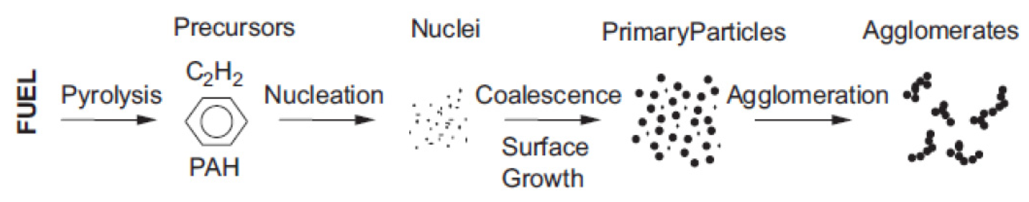
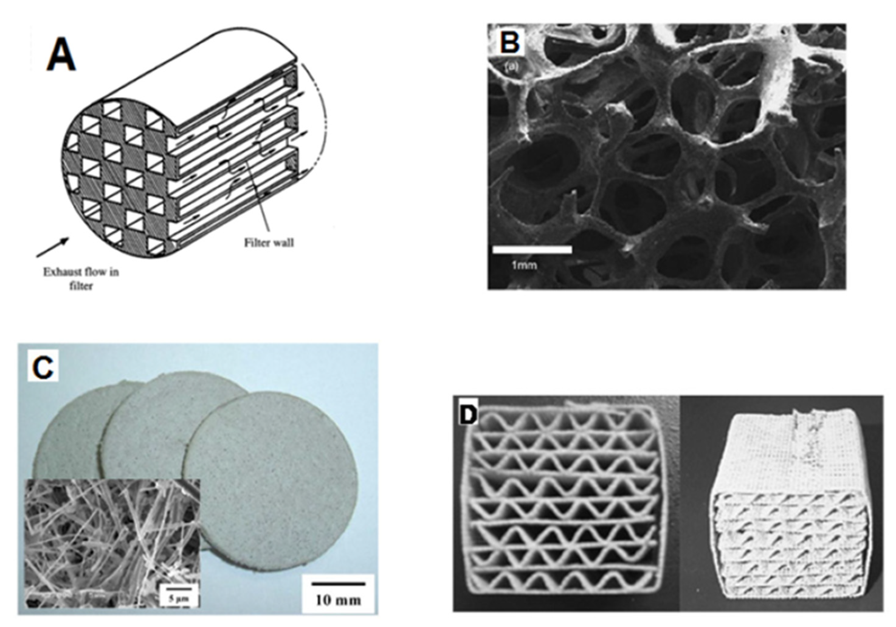
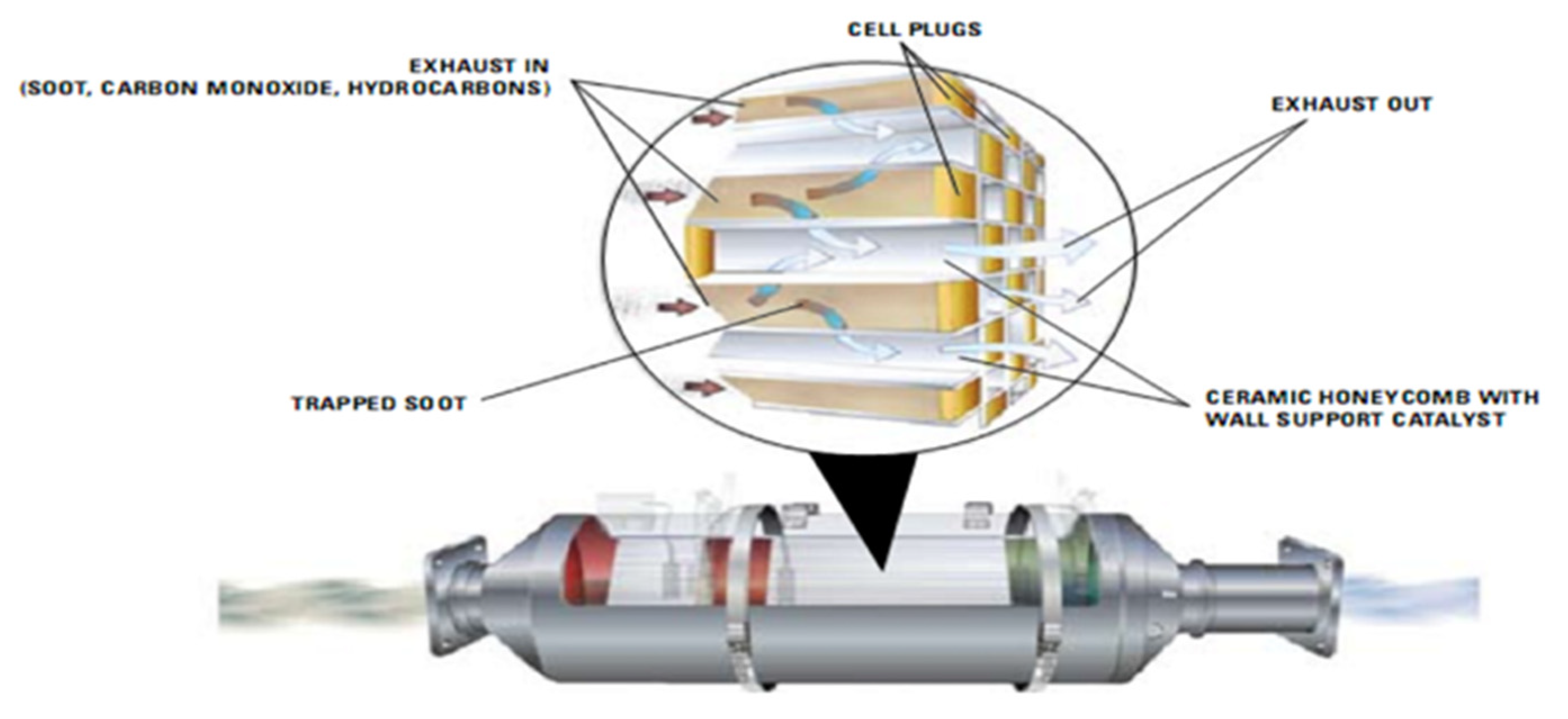
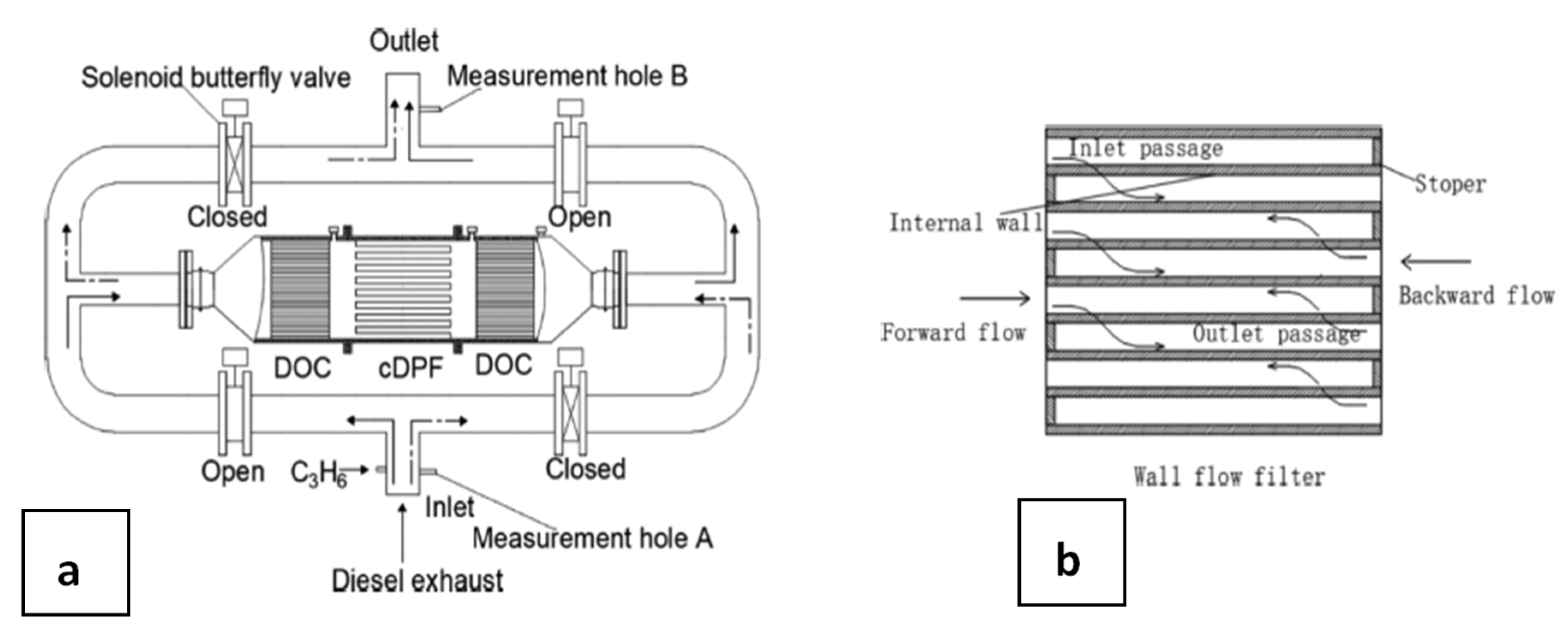
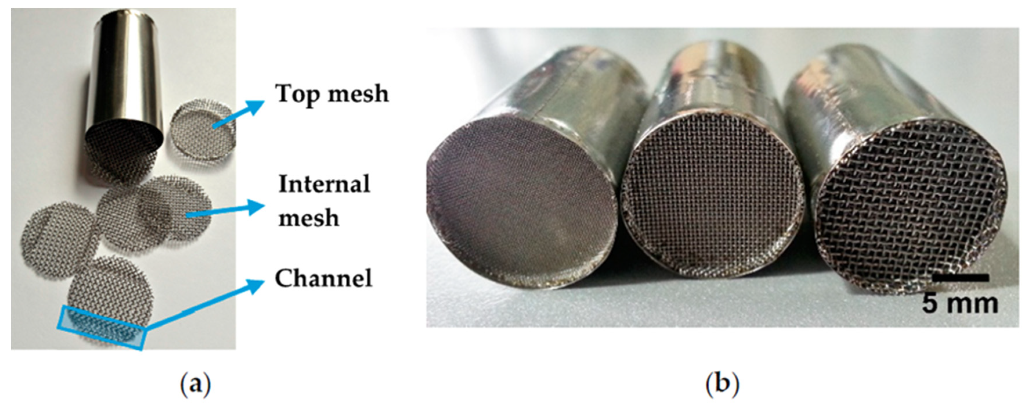
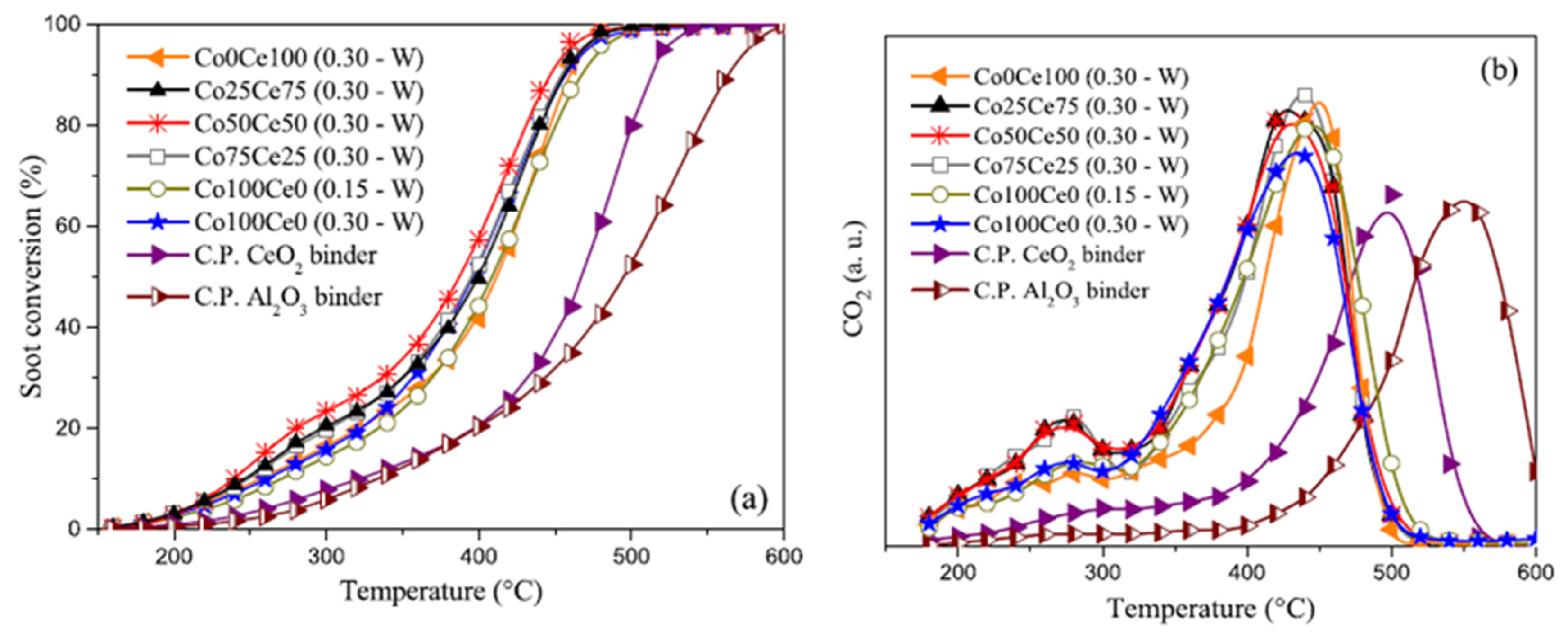
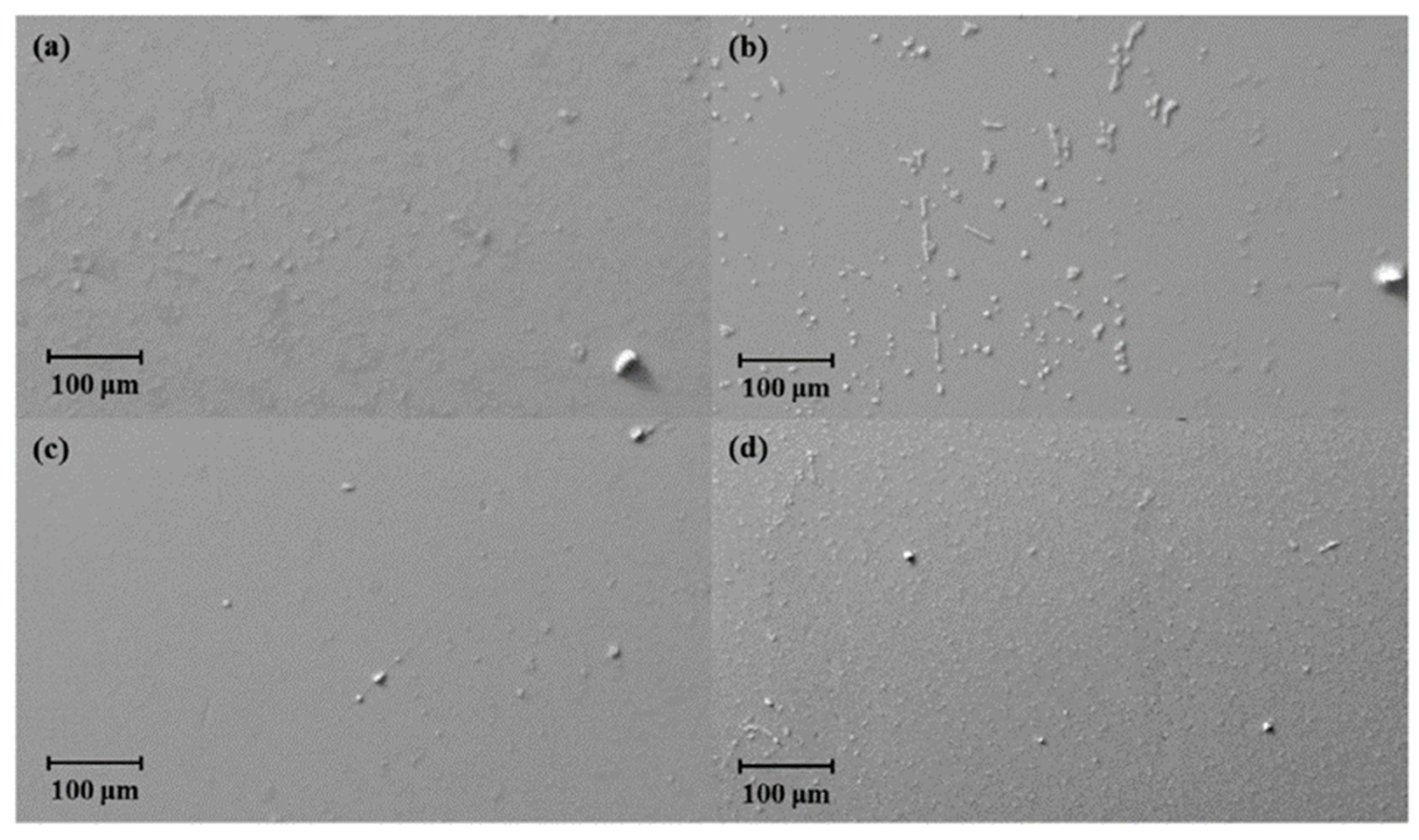
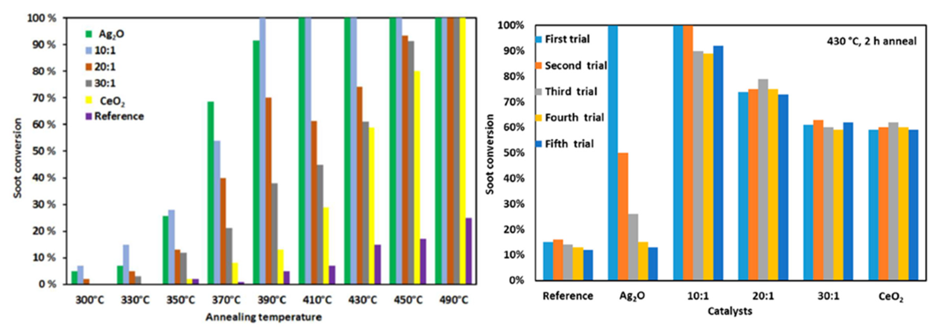
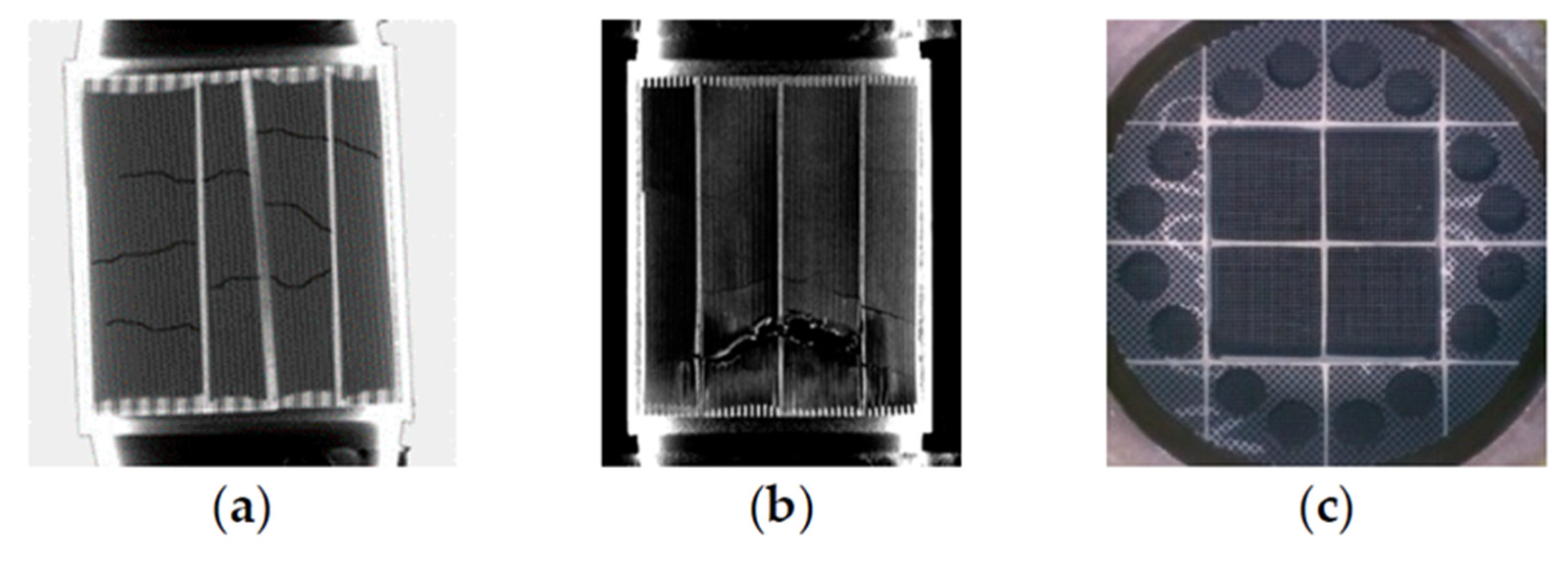
Table 1.
Euro-X emission standards, for both diesel and gasoline-driven light-duty engines.
| Date | CO g km−1 | HC g km−1 | HC + NOx g km−1 | NOx g km−1 | PM g km−1 | PN Particle Number km−1 | |
|---|---|---|---|---|---|---|---|
| Gasoline | |||||||
| Euro 1 | 1992 | 2.72 | - | 0.97 | - | - | - |
| Euro 2 | 1996 | 2.2 | - | 0.5 | - | - | - |
| Euro 3 | 2000 | 2.3 | 0.2 | - | 0.15 | - | - |
| Euro 4 | 2005 | 1.0 | 0.1 | - | 0.08 | - | - |
| Euro 5 | 2009 | 1.0 | 0.1 | - | 0.06 | 0.005 | - |
| Euro 6 | 2014 | 1.0 | 0.1 | - | 0.06 | 0.005 | 6 × 10¹¹ |
| Diesel | |||||||
| Euro 1 | 1992 | 2.72 | - | 0.97 | - | - | - |
| Euro 2, IDI | 1996 | 1.0 | - | 0.7 | - | 0.08 | - |
| Euro 2, DI | 1996 | 1.0 | - | 0.9 | - | 0.10 | - |
| Euro 3 | 2000 | 0.64 | - | 0.56 | 0.5 | 0.05 | - |
| Euro 4 | 2005 | 0.5 | - | 0.3 | 0.25 | 0.025 | - |
| Euro 5a | 2009 | 0.5 | - | 0.23 | 0.18 | 0.005 | - |
| Euro 5b | 2011 | 0.5 | - | 0.23 | 0.18 | 0.005 | 6 × 10¹¹ |
| Euro 6 | 2014 | 0.5 | - | 0.17 | 0.08 | 0.005 | 6 ×1 011 |
CO—carbon monoxide, HC—hydrocarbons, NOx—nitrogen oxides, PM—particulate matter (soot), PN—particle number.
Table 2.
EU Emission Standards for HDV diesel engines [6].
Table 2.
EU Emission Standards for HDV diesel engines [6].
| Date | CO g kWh−1 | HC g kWh−1 | NOx g kWh−1 | PM mg kWh−1 | PN Particle Number kWh−1 | Smoke m−1 | |
|---|---|---|---|---|---|---|---|
| Euro 1, <85 kW | 1992 | 4.5 | 1.1 | 8.0 | 612 | - | - |
| Euro 1, >85 kW | 1992 | 4.5 | 1.1 | 8.0 | 360 | - | - |
| Euro 2a | 1996 | 4.0 | 1.1 | 7.0 | 250 | - | - |
| Euro 2b | 1998 | 4.0 | 1.1 | 7.0 | 150 | - | - |
| Euro 3 | 2000 | 2.1 | 0.66 | 5.0 | 100 | - | 0.8 |
| Euro 4 | 2005 | 1.5 | 0.46 | 3.5 | 20 | - | 0.5 |
| Euro 5 | 2008 | 1.5 | 0.46 | 2.0 | 20 | - | 0.5 |
| Euro 6 | 2013 | 1.5 | 0.13 | 0.4 | 10 | 8 × 10¹¹ | - |
© 2020 by the authors. Licensee MDPI, Basel, Switzerland. This article is an open access article distributed under the terms and conditions of the Creative Commons Attribution (CC BY) license (http://creativecommons.org/licenses/by/4.0/).
Share and Cite
MDPI and ACS Style
Meloni, E.; Palma, V. Most Recent Advances in Diesel Engine Catalytic Soot Abatement: Structured Catalysts and Alternative Approaches. Catalysts 2020, 10, 745. https://0-doi-org.brum.beds.ac.uk/10.3390/catal10070745
AMA Style
Meloni E, Palma V. Most Recent Advances in Diesel Engine Catalytic Soot Abatement: Structured Catalysts and Alternative Approaches. Catalysts. 2020; 10(7):745. https://0-doi-org.brum.beds.ac.uk/10.3390/catal10070745
Chicago/Turabian StyleMeloni, Eugenio, and Vincenzo Palma. 2020. "Most Recent Advances in Diesel Engine Catalytic Soot Abatement: Structured Catalysts and Alternative Approaches" Catalysts 10, no. 7: 745. https://0-doi-org.brum.beds.ac.uk/10.3390/catal10070745
Note that from the first issue of 2016, this journal uses article numbers instead of page numbers. See further details here.