Precise Catalyst Production for Carbon Nanotube Synthesis with Targeted Structure Enrichment


Department of Engineering, University of Cambridge, Cambridge CB2 1PZ, UK
*
Author to whom correspondence should be addressed.
Catalysts 2020, 10(9), 1087; https://0-doi-org.brum.beds.ac.uk/10.3390/catal10091087
Submission received: 20 August 2020
/
Revised: 15 September 2020
/
Accepted: 16 September 2020
/
Published: 19 September 2020
(This article belongs to the Special Issue Catalysts in 1D and 2D Materials—Their Role in Synthesis, Properties and Applications)
Abstract
:The direct growth of single-walled carbon nanotubes (SWCNTs) with a narrow distribution of diameter or chirality remains elusive despite significant benefits in properties and applications. Nanoparticle catalysts are vital for SWCNT synthesis, but how to precisely manipulate their chemistry, size, concentration, and deposition remains difficult, especially within a continuous production process from the gas phase. Here, we demonstrate the preparation of W6Co7 alloyed nanoparticle catalysts with precisely tunable stoichiometry using electrospray, which remain solid state during SWCNT growth. We also demonstrate continuous production of liquid iron nanoparticles with in-line size selection. With the precise size manipulation of catalysts in the range of 1–5 nm, and a nearly monodisperse distribution (σg < 1.2), an excellent size selection of SWCNTs can be achieved. All of the presented techniques show great potential to facilitate the realization of single-chirality SWCNTs production.
1. Introduction
The rational design and synthesis of nano-catalysts with precisely controlled structures, morphologies, and chemical compositions strongly impact the activity and selectivity of catalysts in applications ranging from the growth of single-walled carbon nanotubes (SWCNTs) to clean energy electrochemical reactions [1] such as the oxygen reduction reaction (ORR), oxygen evolution reaction (OER), or hydrogen evolution reaction (HER). Nevertheless, it is often unachievable to produce nano-catalysts with a targeted diameter, narrow size distribution, and specific stoichiometry, particularly if the diameter of the particles is smaller than 5 nm or if the particles should contain an alloyed chemistry. These factors especially hinder the growth of SWCNTs with specific chiralities, which is needed for applications such as next-generation electronics and optoelectronics [2,3].
For the chemical vapor deposition (CVD) of SWCNTs, alloyed catalysts such as W6Co7 [4,5], CoxMoy [6] or CoxNiy [7] introduced new hope for the in situ enrichment of certain SWCNT chiralities. However, among the reported methods, synthesis of key alloyed catalysts is still restricted by the random nucleation from the colloidal solution [6] and aerosol [7], or use of specific organic molecules [4]. Precisely manipulating the chemistry of every single tiny alloyed nanoparticle (<5 nm) then becomes critical but difficult, because of the common stoichiometry deviation between catalysts during catalyst nucleation and growth, which can affect the crystalline structure and the uniformity of catalyst performance.
On the other hand, because of the diameter correlation between the SWCNT and catalyst, a chemistry-independent method to precisely control catalyst sizes smaller than 2 nm is a long-sought goal. Recently, our group showed the first study to realize the continuous synthesis of solid catalysts (W-, Mo-, and Re-based) with a size smaller than 2 nm [8]. These solid catalysts remain in a solid state in the high-temperature CNT growth environment. However, although regarded more efficient on catalyzing CNT growth with special enhanced enrichment of near-armchair chiralities, the corresponding continuous synthesis of liquid catalysts (Fe-, Ni-, and Co-based) also with precise size manipulation is still missing. Additionally, the size-dependent influence on SWCNTs also needs to be confirmed.
Here, we present the first study on the use of electrospray techniques to continuously produce W6Co7 alloyed nanoparticles with precisely manipulated stoichiometry and size. On the other hand, we also present a continuous production method for typical liquid catalysts—Fe-based nanoparticles—using straightforward gas-phase synthesis and in-line size selection techniques. This allows for a precisely manipulated size to any target value in the region of 1–8 nm and a narrow size distribution. The constraint effect on the diameter of SWCNTs (dt) can be clearly seen. These new advances are important to develop future continuous synthesis methods for chirality-controlled SWCNTs.
2. Results
2.1. Production of Alloyed Nano-Catalysts and Their Growth of CNTs
2.1.1. Nanoparticle Production from Electrospray Method with Precise Stoichiometry
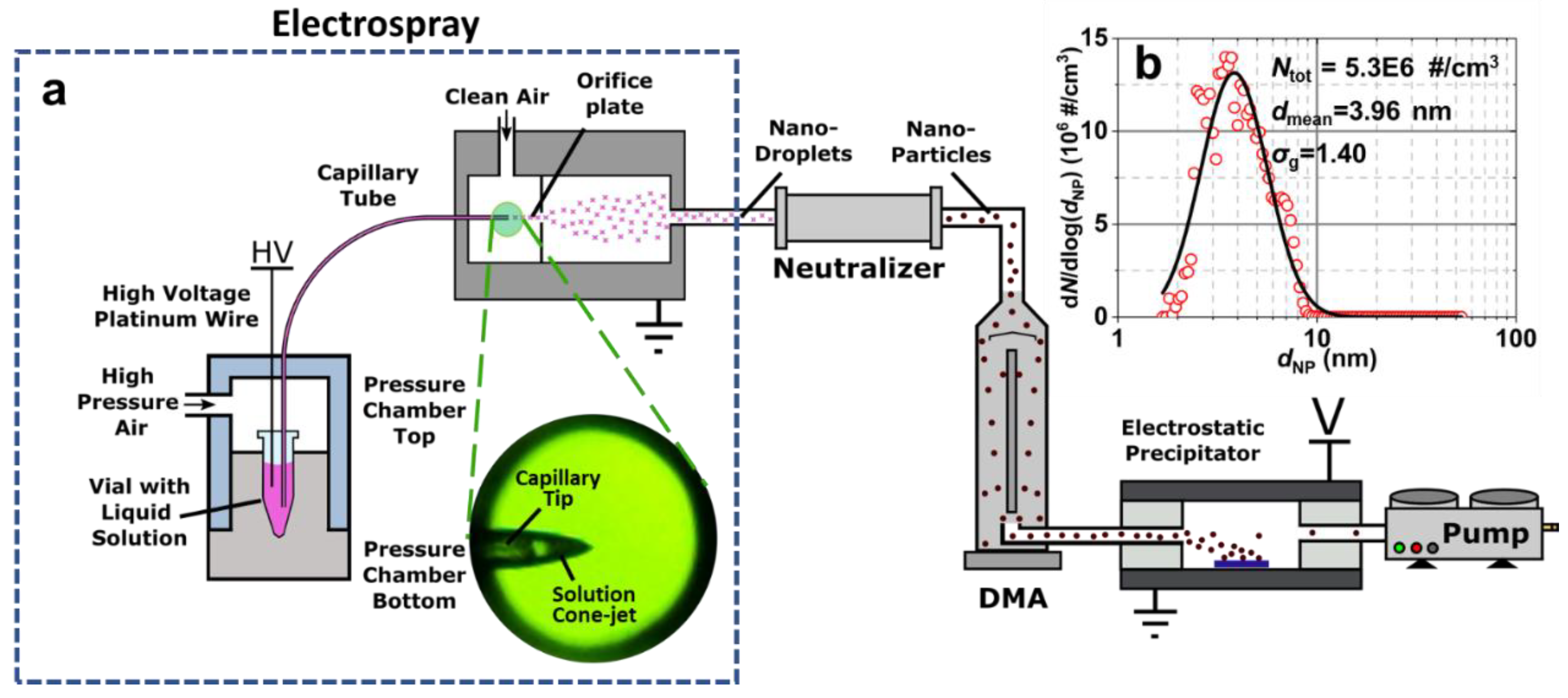
With W-Co alloyed catalysts as an example, synthesis begins with the generation of gas-phase W-Co compound salt nanoparticles (sNPs) suspended in a carrier gas, as shown in Figure 1. With the gas-phase transport, sNPs pass through size selection and controlled deposition. The W-Co alloyed catalyst (refractory-ferromagnet metal alloyed catalyst) is a typical solid catalyst to support the growth of SWCNTs, which remain rigid and crystalline in a CNT growth environment, believed to strongly affect the chirality enrichment in the final product [4,6].
As shown in Figure 1a, the mixed solution of W- and Co-based compounds passes through a capillary tube driven by the high gas pressure. Under optimized parameters, the solution cone formed at the tip of the capillary facilitates the jet of nano-droplets driven by the high voltage difference between the cone and the orifice plate. The jetted highly charged nano-droplets are timely neutralized and self-dried in the carrier gas, forming the sNPs.
The size distributions of sNPs are first characterized by a scanning mobility particle spectrometer (SMPS) (Figure 1b). Owing to the nanoscale of the droplet jet, the nanoparticles (sNPs) formed after solvent removal are well constrained to < 8 nm with a mean diameter (dmean) ~ 3.96 nm, which is much smaller than sNPs formed by a common atomizer (>10 nm) [8,9].
After constraining the sNP size with cone-jetting, the size distributions of the sNPs are further narrowed by a differential mobility analyzer (DMA). In the following section of this work (for liquid catalysts), the size selection principle of the DMA will be illustrated in detail. With the final controlled disposition onto various target substrates by an electrostatic precipitator, sNPs are evenly distributed on the collection zone with a tunable areal density (Figure 2a). The size distribution of selected NPs follows a log-normal distribution with a geometric standard deviation (σg) of 1.21 based on AFM statistics, much smaller than the that before DMA size selection (σg = 1.40). σg can be further lowered to 1.05 based on our previous research [8] as long as the aerosol concentration is high enough to guarantee efficient collection.
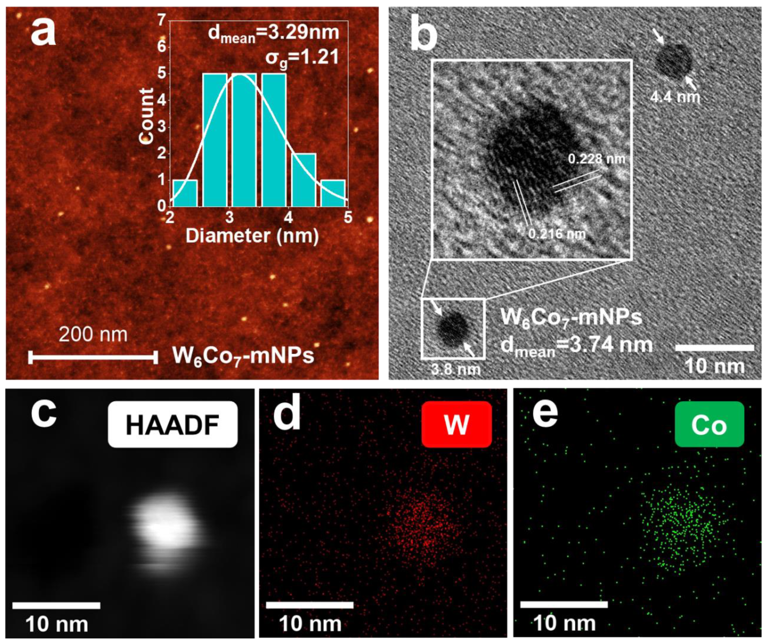
After calcination and reduction at high temperature in H2, the sNPs are reconstructed into single-crystal alloyed NPs (alloyed-mNPs, Figure 2b–e). Based on our previous work, the diameter is observed to shrink by ~40% (60% remaining) during this process after losing O, N, and H and reconstruction [8]. Energy-dispersive X-ray spectroscopy (EDS) elements mapping verifies that both W and Co elements are uniformly distributed across the alloyed-mNPs. The atomic ratio of W/Co measured by EDS is (42.3 ± 7.1): (57.8 ± 8.3). Combined with the interplanar distances of mNPs measured from HRTEM, our particles’ characteristics are in good agreement with those of W6Co7 (PDF exp.2-1091). Figure 2b inset shows interplanar distances 0.216 and 0.228 nm of the (1 0 10) and (1 1 3) planes in the W6Co7 alloy, respectively. Moreover, no accumulation of oxygen is seen in the area of the NPs, verifying the alloyed metal state of the NPs. We suggest the alloyed-mNPs are W6Co7 alloyed single crystals (details of the crystal structure identification can be found in the Supplementary Material).
Importantly, with this electrospray method, each nanoparticle is formed from one nano-droplet, thus the stoichiometry of the sNPs and mNPs is precisely equal to the solution from which the nano-droplets are formed. Here, the atomic ratio of W/Co in the prepared mixed solution is 6:7, matching the stoichiometry of W6Co7 catalysts and the EDS results.
2.1.2. CNTs Grown from the Alloyed Nano-Catalysts
The NPs produced in this work are based on a continuous gas-phase process. In our previous work, we demonstrated its potential to be extended into a floating catalyst CVD process (FCCVD) [8]. However, for the sake of convenience, and a better control on the synthesis parameters of NPs and CNTs, all the CNTs in this work are grown using a batch process from substrates loaded by produced NPs.
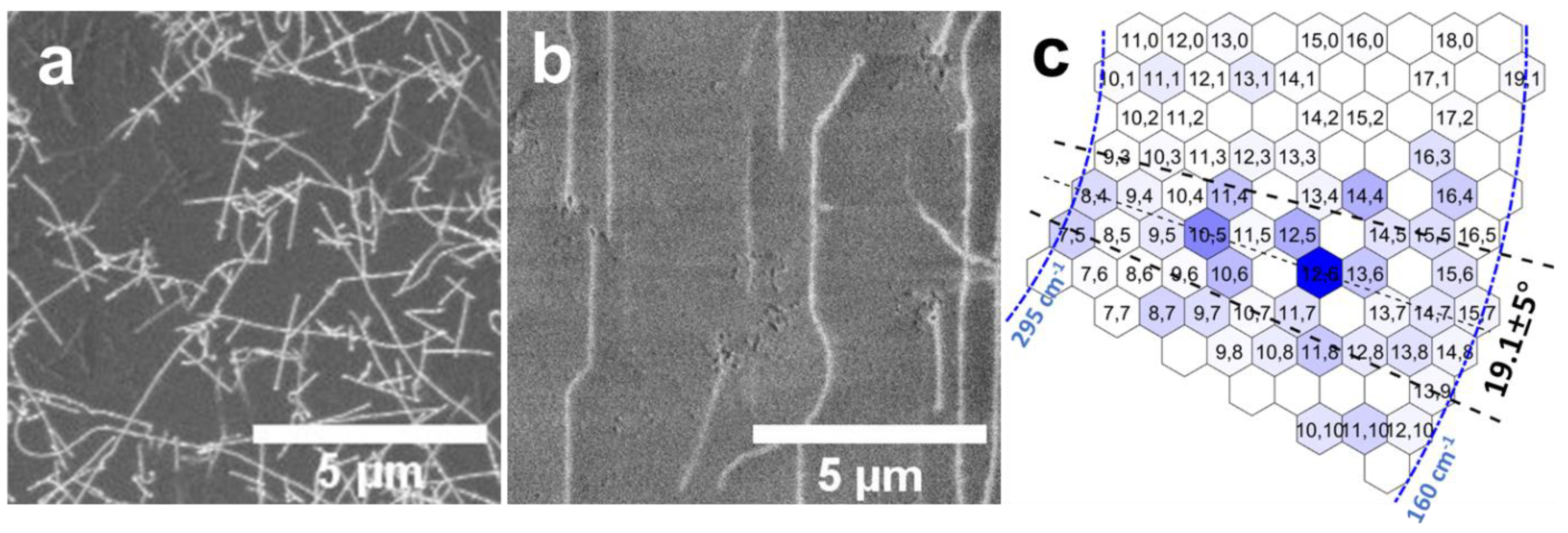
Due to the gas-phase nature of the sNPs formation process, by modifying the receiving target substrates, CNTs can be facilely grown on various targets without any ex situ transfer processes. Figure 3 shows random CNTs grown on SiO2/Si (Figure 3a) and an aligned array (Figure 3b) on the ST-cut quartz substrate because of the guidance from the atom steps of the substrate [10]. By decoupling the catalyst size from the areal density, further growth of high-density SWNT arrays for electronics becomes possible [11,12]. Moreover, it is worth noting that in SEM images of CNTs laying on an insulating substrate (SiO2/Si) obtained with a low accelerating voltage (1–3 kV), the bright line in the images (Figure 3a,b) originates from not only the CNT itself, but also from the adjacent zone of substrate affected by the CNT [13]. Therefore, the diameter of the bright lines cannot represent that of CNTs.
With radial breathing mode (RBM) peaks from the resonant Raman spectroscopy of SWCNTs detected with 532, 638, and 785 nm lasers, the chiralities abundances are identified based on the Kataura plot and summarized in a graphene map (Figure 3c). To guarantee unambiguous identification, the color density is indicative of solely SWCNTs within 0.81–1.53 nm (160–295 cm−1, marked by the blue dash-dotted line). Chiralities near (2n,n) most enriched (corresponding range of 19.1 ± 5°) are marked by a black dashed line, and few can be found near the zigzag region. The most enriched visible chiralities are (12,6), (10,5), (13,6), and (12,5), which are all on or near (2n,n), with the chiral angle near 19.1°. This result matches the solid catalysts performance we reported recently [8]. The highest abundance of (12,6) reached approximately 22% among the diameter range of 0.81–1.53 nm. The slightly lower abundance compared with a previous report is mainly because of the comparatively larger size of the W-Co alloyed catalyst with the electrospray method, which is a compromise to reach a higher catalyst production rate and collection efficiency. Currently, the yield of our electrospray method is around 101–103 #/cm3/min, which set up many difficulties on characterization and size selection. However, significant advancements in electrospray have been made in recent years as a part of a large effort by the synthesis community [14]. The yield can also be improved in the future by using electrospray with multi cone jets, instead of a single one used here. Considering the unique advantage of the electrospray method on the manipulation of stoichiometry in the nano-catalyst, further work could effectively reduce the size of the alloyed catalyst and further constrain chiralities.
2.2. Production of Size-manipulated Fe-based Catalyst and the SWCNTs Diameter Constraint
2.2.1. Fe2O3 Nanoparticle Production with Precise Size Manipulation
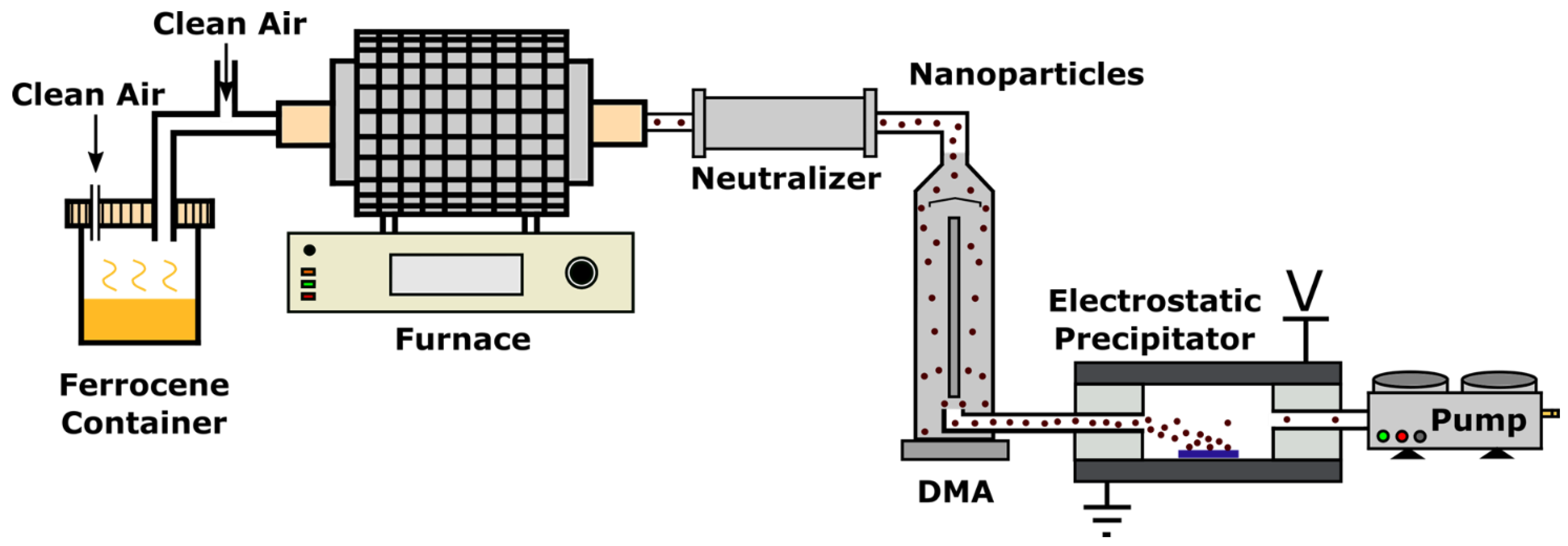
For liquid iron catalysts, we follow our reported techniques [8] to produce metal oxide nanoparticles (oNPs) in the gas phase. Then, to grow SWCNTs, the Fe-oNPs are reduced into Fe metal nanoparticles (Fe-mNPs), forming the final catalyst upon the supply of the carbon feedstock. As shown in Figure 4, the ferrocene vapor taken by the carrier air gas enters the high-temperature furnace (700 °C), and is calcinated into Fe-oNPs. The dominant sizes of Fe oNPs are adjustable from 2 to 10 nm by varying the input of the Fe precursor (temperature of the ferrocene container and the flow rate of the carrier air gas).
Although small and highly concentrated, Fe-oNPs’ size is still too broadly distributed to effectively constrain the diameter of SWCNTs. Similar to the techniques above, proactive NP mobility selection is integrated into the mainstream to transform the distribution of the entire aerosol flow from polydisperse to monodisperse. In this process, after being charged by a radioactive ionizer, the oNPs are passed between two concentric cylinders in the DMA at an electrical potential difference. Only oNPs with the prescribed mobility-equivalent diameter pass downstream, which results in the narrow size distribution of the selected Fe-oNPs.
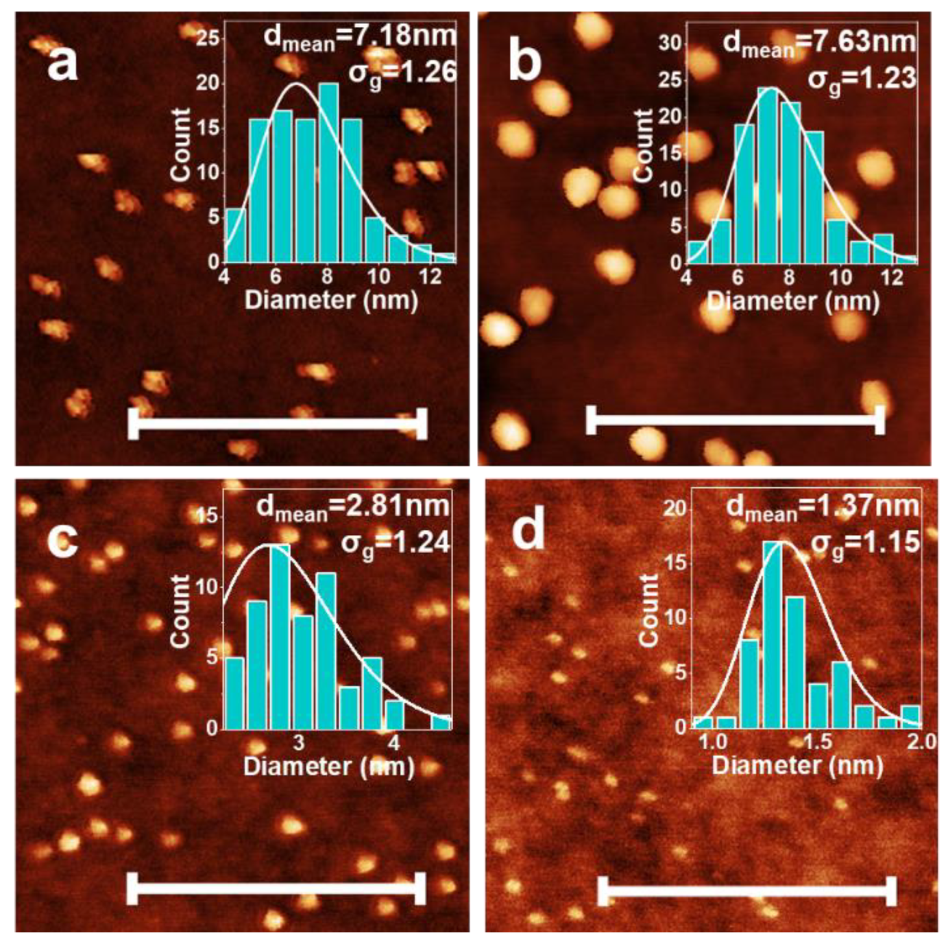
Using AFM, the size distribution of these selected Fe NPs is measured (Figure 5a–d). Their sizes are precisely tuned in the range of 1 to 8 nm. From relatively large Fe-oNPs (Figure 5a), it is obvious that the as-produced Fe-oNPs are nanoaggregates with irregular morphologies. After being processed in H2 at 400 °C, the nanoaggregates are reduced and reconstructed into rounded NPs (and inevitably re-oxidized in the air when characterized by AFM). Meanwhile, for all sizes, the size distribution after selection is inherited to that of NPs after reduction and reconstruction (Figure 5a–d, σg ~ 1.2, and σg = 1 represents ideal monodisperse particles). This implies that processing in H2 at 400 °C for 5 min will not broaden the size distribution although the aggregation and Ostwald ripening effect are enhanced.
It is also worth noting that the absolute FWHM of these selected distributions scales with the selected midpoint size. Therefore, the selection of smaller-diameter particles also corresponds to a smaller FWHM (insets of Figure 5b–d, FWHM decreases from 3 to 0.5 nm when dmean decreases from 7.6 to 1.4 nm). This is the key feature for achieving nearly monodisperse Fe catalysts for SWCNT growth.
2.2.2. Constrain SWCNTs Diameter by Fe Catalysts
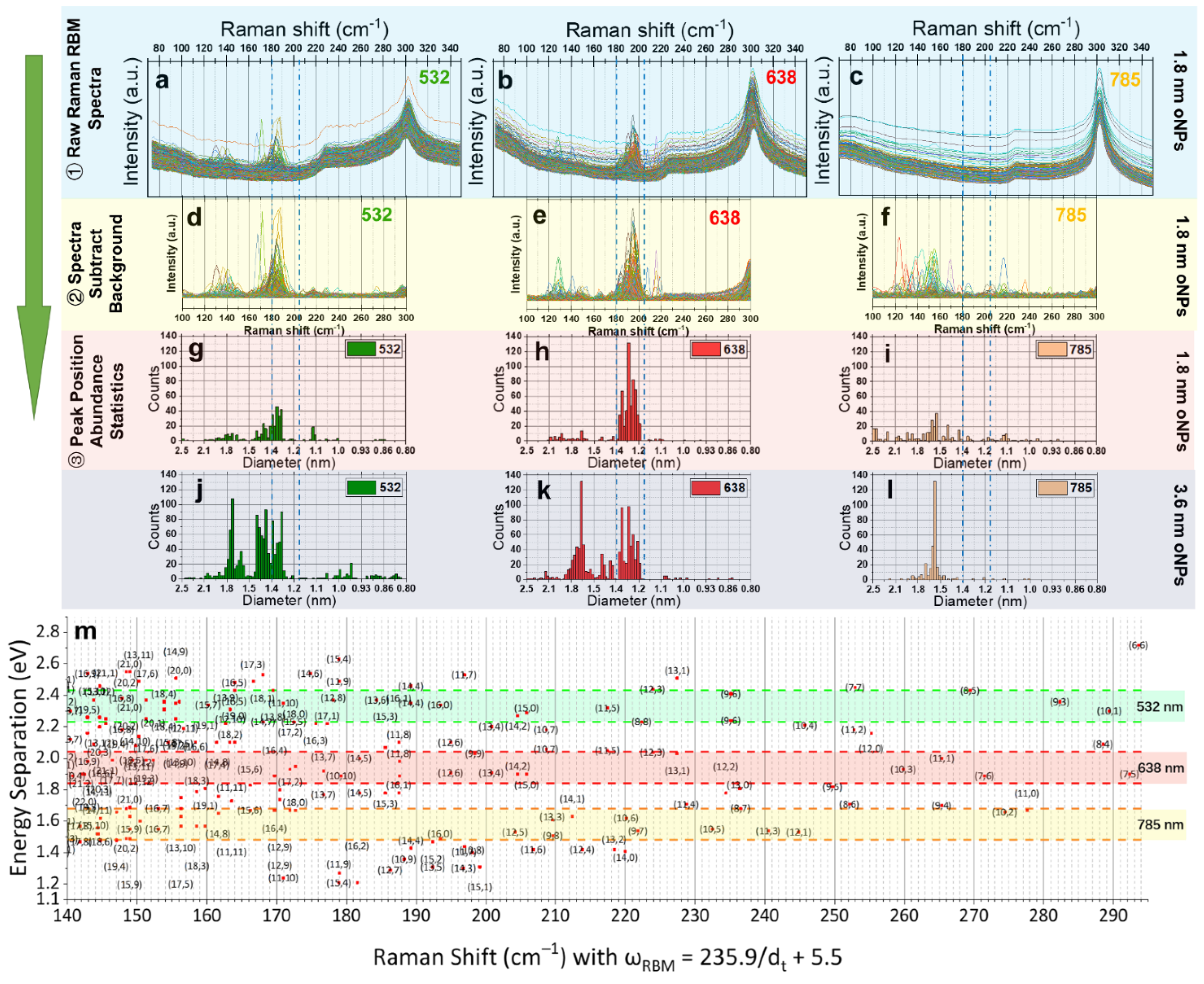
In Figure 6, we compare the diameter distribution of SWCNTs grown from size-selected 1,8 (Figure 6a–i) and 3.6 nm (Figure 6j–l) Fe-oNPs catalysts. Resonant Raman spectroscopy shows the RBM peaks of SWCNTs in the laser spot excited with laser phonons [3,15]. We follow our reported method [8] on Raman mapping characterization and data analysis. In Figure 6a–c, we show the raw Raman spectra of 1.8 nm Fe-oNPs on the RBM region detected by 532, 638, and 785 nm lasers.
The peak position of each spectrum is identified after background removal (SiO2/Si signal, Figure 6d–f). Based on the RBM peaks frequency (ωRBM) to the diameter of SWCNTs (dt) relationship for samples grown on SiO2/Si substrates [16], ωRBM = 235.9/dt + 5.5, we obtain the diameter distribution statistics from the peak position abundance statistics results (Figure 6g–l).
Here, with Raman 2D mapping results from 532, 638, and 785 nm lasers, the resonant peak position abundance statistics results are summarized with a normalized scale so that peak counts can be compared between different lasers. However, as is well known, the scale of detectable SWCNTs in each Raman mapping result depends on both the diameter distribution of the sample and whether resonance happens with the laser wavelength, according to the Kataura plot [17,18], as shown in Figure 6m.
In our results, for abundance detected by the 638 nm laser (Figure 6h vs. Figure 6k), it is clear that 1.8 nm Fe-oNPs catalysts preferentially produce more 1.2–1.4 nm SWCNTs and fewer for dt > 1.4 nm.
A similar trend can also be seen by the 532 nm laser (Figure 6g vs. Figure 6j), where SWCNTs with dt > 1.4 nm are much suppressed with 1.8 nm Fe-oNPs catalysts, although 1.2 < dt < 1.3 nm cannot be detected by the 532 nm laser because of a lack of resonance and the known bias of the chirality distribution to the armchair chiralities with liquid catalysts like Fe [19].
For the 785 nm laser results (Figure 6i vs. Figure 6l), the disappearance of 1.2–1.4 nm SWCNTs enrichment is also due to the poor resonance condition and the chirality distribution propensity for armchair chiralities. The suppressed abundance peak around 1.6 nm tends to verify the constraint effect from the size of the catalysts.
3. Discussion
To pursue single-chirality SWCNT growth, the mechanisms underlying the chirality selection of SWCNTs are of great importance. However, many theoretical contributions have been proposed, but always lack sound experimental verification. Among them, interface energy-driven nucleation thermodynamics [20,21,22] combined with CNT growth kinetics [20], as well as catalyst epitaxy with symmetry matching [4,23,24], are the most favorable directions.
Before the realization of chirality enrichment, normally specific diameter enrichment in the SWCNT product is the precondition. However, not all the grown SWCNTs possess diameters to match those of their catalysts, which is known as tangential growth (dt ~ dcatalyst). Sometimes, the diameter of a grown SWCNT can be smaller than that of its catalyst (dt < dcatalyst), and this is known as perpendicular growth.
With in-line size selection using a DMA, we can directly select small-diameter catalysts. Although CNT growth is not fixed to either perpendicular growth or tangential growth, small catalysts provide a limited upper bound to the diameter of CNTs regardless of the growth mode. Here, we verified, with 1.8 nm Fe-oNPs, that the diameter of SWCNTs can be enriched <1.4 nm. Consequently, the resultant chirality choices are significantly reduced. Further, combined with the declined chiral angle distribution, the chirality choices are again reduced.
The SWCNT diameter distribution results from 1.8 nm Fe-oNPs also imply that the size distribution of catalysts set by NP mobility size selection can still be inherited by SWCNTs, even though Fe is believed to remain in a liquid state during CNT growth and lead to more aggregation and Ostwald ripening than solid catalysts.
With the electrospray technique, owing to its chemistry-independent property, as long as mixed solutions of the corresponding soluble compounds are prepared, similar alloyed catalysts such as Mo-Fe, W-Fe, and Re-Ni can also be produced with precise manipulation of the stoichiometry.
Further, combined with proper processing, the formed single-crystal nano-catalysts with different chemistry and stoichiometry give researchers, for the first time, an ability to manipulate the interface between the CNT and catalyst, where the interfacial energy has been reported to determine the chiral preference of SWCNTs by affecting the possibility of nucleation, the growth speed, and even the growth time.
4. Conclusions
With the mechanism of one nanoparticle formed from one atomized droplet, we produce W6Co7 alloyed nanoparticles successfully with the same target chemistry in a continuous gas-phase method. They act as the solid catalyst to grow SWCNTs with chirality control. As an example, for liquid catalysts, we produce the gas-phase size-selected Fe-based nanoparticles with a size down to 1.5–1.8 nm. The small diameter of these liquid catalysts shows an obvious diameter constraint effect on SWCNTs, with the diameter highly enriched to <1.4 nm.
We assert that the two techniques shown here can be used to provide a useful set of experimental designs to support or rule out potential theoretical mechanisms, facilitating measuring the physical parameters, and finally forming a cohesive and useful theory that can guide the development of models, experiments, and the production of chirality-controlled CNTs.
5. Materials and Methods
5.1. Nanoparticle Synthesis, Size Selection, and Collection
Production of alloyed W6Co7-nanoparticles: An aqueous mixed metal salt solution was prepared with 25 μM (NH4)6H2W12O40 (Sigma-Aldrich 463922), 350 μM Co(NO3)2·6H2O (Sigma-Aldrich 203106), and 20 mM CH3CO2NH4 (Sigma-Aldrich A1542, as a buffer agent which will vaporize before size selection). The mixed solution was atomized into nano-droplets suspended in clean air as a carrier gas through an electrospray aerosol generator (TSI Inc. 3480, Minnesota USA). For the electrospray process, a silica capillary with an inner diameter of 40 μm was used to obtain a cone-jetting mechanism with a proper flow rate of carrier gas (~2 slpm) and 2 kV high voltage. A radioactive charge neutralizer (TSI 3077) was used to discharge the nano-droplet to avoid splitting with the removal of water in the nano-droplet, leaving precipitated sNPs. The sNPs were then sent through a DMA (TSI 3085). The DMA selected particles with a prescribed mobility-equivalent diameter and a very narrow range. The DMA-selected nanoparticles were sent into an electrostatic precipitator for collection onto the target substrate.
Production of size-selected Fe-oNPs: Clean air (20 sccm) was set to pass through the container of ferrocene powder (Sigma-Aldrich F408) at room temperature. Another clean air (1 slpm) carried the vapor of ferrocene through an alumina tube in a furnace whose temperature was set to 700 °C, and the nucleated polydisperse Fe-oNPs were first charged using a radioactive charge neutralizer (TSI 3077). Production of alloyed W6Co7-nanoparticles: An aqueous mixed metal salt solution was prepared with 25 μM (NH4)6H2W12O40 (Sigma-Aldrich 463922), 350 μM Co(NO3)2·6H2O (Sigma-Aldrich 203106), and 20 mM CH3CO2NH4 (Sigma-Aldrich A1542, as a buffer agent which will vaporize before size-selection). The mixed solution was atomized into nano-droplets suspended in clean air as a carrier gas through an electrospray aerosol generator (TSI Inc. 3480, Minnesota USA). For the electrospray process, a silica capillary with an inner diameter of 40 μm was used to obtain a cone-jetting mechanism with a proper flow rate of carrier gas (~2 slpm) and 2 kV high voltage. A radioactive charge neutralizer (TSI 3077) was used to discharge the nano-droplet to avoid splitting with the removal of water in the nano-droplet, leaving precipitated sNPs. The sNPs were then sent through a DMA (TSI 3085). The DMA selected particles with a prescribed mobility-equivalent diameter and a very narrow range. The DMA-selected nanoparticles were sent into an electrostatic precipitator for collection onto the target substrate.
To avoid or reduce possible aggregation, oNPs were first reduced in H2 with the temperature slowly rising to 400 °C to obtain mNPs. Then, the temperature was raised quickly to 850 °C (100 K/min). Ethanol vapor as the carbon feedstock was introduced immediately when the final temperature was reached (850 °C) in an Ar carrier gas stream. The growth time was set to only 10 min. After growth, the carbon-rich environment was expelled by H2, and the samples were cooled to room temperature.
5.2. Aerosol Characterization, AFM, HRTEM, EDS, and Raman Mapping
Aerosol size distributions of all NPs were analyzed using a scanning mobility particle spectrometer (SMPS, TSI 3938, Minnesota USA), which consists of a combination of a DMA (TSI 3085, Minnesota USA) and a condensation particle counter (CPC, TSI 3756, Minnesota USA). AFM was conducted on a Veeco Dimension Pro AFM in peak force mode. Both transmission electron microscopy (TEM, Thermo Scientific Talos) and energy-dispersive X-ray spectroscopy (EDS) elements mapping were conducted on a Thermo Scientific (FEI) Talos F200X G2 TEM operating at 200 kV. TEM images were acquired using a Ceta 16M CMOS camera. EDS was performed in scanning transmission electron microscopy (STEM) mode with images acquired using the high-angle annular dark field (HAADF) detector with EDX spectra/maps collected using the Super-X EDS detector system which consists of 4 windowless silicon drift detectors. Prior to TEM, the NPs were dispersed onto Si3N4 TEM grids. Raman mapping was conducted in the RBM range, with 532, 638, and 785 nm lasers (HORIBA XploRA PLUS). The step size is set to 3 μm in both the x and y directions.
6. Patents
The pertaining UK patent has been filed with the application number as 1917638.7., which partially results from the work reported in this manuscript.
Supplementary Materials
The following are available online at https://0-www-mdpi-com.brum.beds.ac.uk/2073-4344/10/9/1087/s1, Table S1: Interplanar spacings statistics of alloyed mNPs measured from HRTEM, Table S2: Interplanar spacings information of W6Co7 (PDF exp.2-1091) in the range of 0.18–0.32 nm.
Author Contributions
Conceptualization, X.Z., B.G., M.D.V. and A.B.; methodology, X.Z., Y.D., B.G., M.D.V. and A.B.; validation, X.Z., Y.D., B.G., M.D.V. and A.B.; formal analysis, X.Z.; data curation, X.Z.; writing—original draft preparation, X.Z. and Y.D.; writing—review and editing, B.G., M.D.V. and A.B.; supervision, M.D.V. and A.B.; project administration, A.B.; funding acquisition, A.B., X.Z. All authors have read and agreed to the published version of the manuscript.
Funding
This research was funded by EPSRC project “Advanced Nanotube Application and Manufacturing (ANAM) Initiative” [grant numbers EP/M015211/1] and EPSRC Underpinning Multi-439 User Equipment Call [grant numbers EP/P030467/1], the National Key R&D Program of China (Grant 440 No. 2018YFA0208402), and the National Natural Science Foundation of China (Grant Nos. 11634014 441 and 51820105002). The APC was funded by Cambridge University’s RCUK and/or COAF block grants.
Acknowledgments
The authors specially thank Maksim Mezhericher, Weiya Zhou, Huaping Liu, Kaihui Liu, and Fengrui Rao for their useful guidance and information. The authors thank Mingzhao Wang, Zhanyu Wang, Sarah Stevenson, Yanchun Wang, Liron Issman, and Fiona Smail for their kind support and useful discussion. The author also thank Heather Greer, Adarsh Kaniyoor, and Jenny Mizen for TEM and Raman experiment support.
Conflicts of Interest
The authors declare no conflict of interest. The funders had no role in the design of the study; in the collection, analyses, or interpretation of data; in the writing of the manuscript, or in the decision to publish the results.
References
- Li, Y.; Wang, H.; Priest, C.; Li, S.; Xu, P.; Wu, G. Advanced Electrocatalysis for Energy and Environmental Sustainability via Water and Nitrogen Reactions. Adv. Mater. 2020. [Google Scholar] [CrossRef]
- De Volder, M.; Tawfick, S.H.; Baughman, R.; Hart, A.J. Carbon Nanotubes: Present and Future Commercial Applications. Science 2013, 339, 535–539. [Google Scholar] [CrossRef] [Green Version]
- Zhang, X.; Song, L.; Cai, L.; Tian, X.; Zhang, Q.; Qi, X.; Zhou, W.; Zhang, N.; Yang, F.; Fan, Q.; et al. Optical visualization and polarized light absorption of the single-wall carbon nanotube to verify intrinsic thermal applications. Light. Sci. Appl. 2015, 4, e318. [Google Scholar] [CrossRef] [Green Version]
- Yang, J.; Wang, X.; Zhang, D.; Yang, J.; Luo, D.; Xu, Z.; Wei, J.; Wang, J.; Xu, Z.; Peng, F.; et al. Chirality-specific growth of single-walled carbon nanotubes on solid alloy catalysts. Nature 2014, 510, 522–524. [Google Scholar] [CrossRef] [PubMed]
- Zhao, X.; Yang, J.; Chen, J.; Ding, L.; Liu, X.; Yao, F.; Li, M.; Zhang, D.; Zhang, Z.; Liu, X.; et al. Selective growth of chirality-enriched semiconducting carbon nanotubes by using bimetallic catalysts from salt precursors. Nanoscale 2018, 10, 6922–6927. [Google Scholar] [CrossRef] [PubMed]
- Bachilo, S.M.; Balzano, L.; Herrera, J.E.; Pompeo, F.; Resasco, D.E.; Weisman, R.B. Narrow (n,m)-Distribution of Single-Walled Carbon Nanotubes Grown Using a Solid Supported Catalyst. J. Am. Chem. Soc. 2003, 125, 11186–11187. [Google Scholar] [CrossRef]
- Ahmad, S.; Liao, Y.; Hussain, A.; Zhang, Q.; Ding, E.-X.; Jiang, H.; Kauppinen, E.I. Systematic investigation of the catalyst composition effects on single-walled carbon nanotubes synthesis in floating-catalyst CVD. Carbon 2019, 149, 318–327. [Google Scholar] [CrossRef]
- Zhang, X.; Graves, B.; Volder, M.D.; Yang, W.; Johnson, T.; Wen, B.; Su, W.; Nishida, R.; Xie, S.; Boies, A. High Precision Solid Catalysts for Investigation of Carbon Nanotube Synthesis and Structure. Sci. Adv. 2020, in press. [Google Scholar]
- Johnson, T.J.; Irwin, M.; Symonds, J.P.; Olfert, J.S.; Boies, A.; Martin, I. Measuring aerosol size distributions with the aerodynamic aerosol classifier. Aerosol Sci. Technol. 2018, 52, 655–665. [Google Scholar] [CrossRef]
- Yuan, D.; Ding, L.; Chu, H.-B.; Feng, Y.; McNicholas, T.P.; Liu, J. Horizontally Aligned Single-Walled Carbon Nanotube on Quartz from a Large Variety of Metal Catalysts. Nano Lett. 2008, 8, 2576–2579. [Google Scholar] [CrossRef] [Green Version]
- Kang, L.; Zhang, S.; Li, Q.; Zhang, J. Growth of Horizontal Semiconducting SWNT Arrays with Density Higher than 100 tubes/μm using Ethanol/Methane Chemical Vapor Deposition. J. Am. Chem. Soc. 2016, 138, 6727–6730. [Google Scholar] [CrossRef] [PubMed]
- Hu, Y.; Kang, L.; Zhao, Q.; Zhong, H.; Zhang, S.; Yang, L.; Wang, Z.; Lin, J.; Li, Q.; Zhang, Z.; et al. Growth of high-density horizontally aligned SWNT arrays using Trojan catalysts. Nat. Commun. 2015, 6, 6099. [Google Scholar] [CrossRef] [PubMed]
- Li, J.; He, Y.; Han, Y.; Liu, K.; Wang, J.; Li, Q.; Fan, S.; Jiang, K. Direct Identification of Metallic and Semiconducting Single-Walled Carbon Nanotubes in Scanning Electron Microscopy. Nano Lett. 2012, 12, 4095–4101. [Google Scholar] [CrossRef] [PubMed]
- Parhizkar, M.; Reardon, P.; Knowles, J.; Browning, R.J.; Stride, E.; Pedley, R.; Grego, T.; Edirisinghe, M. Performance of novel high throughput multi electrospray systems for forming of polymeric micro/nanoparticles. Mater. Des. 2017, 126, 73–84. [Google Scholar] [CrossRef]
- Zhang, X.; Yang, F.; Zhao, D.; Cai, L.; Luan, P.; Zhang, Q.; Zhou, W.; Zhang, N.; Fan, Q.; Wang, Y.; et al. Temperature dependent Raman spectra of isolated suspended single-walled carbon nanotubes. Nanoscale 2014, 6, 3949–3953. [Google Scholar] [CrossRef]
- Zhang, D.; Yang, J.; Yang, F.; Li, R.; Li, M.; Ji, D.; Li, Y. Assignments and quantification for single-walled carbon nanotubes on SiO2/Si substrates by resonant Raman spectroscopy. Nanoscale 2015, 7, 10719–10727. [Google Scholar] [CrossRef]
- Kataura, H.; Kumazawa, Y.; Maniwa, Y.; Umezu, I.; Suzuki, S.; Ohtsuka, Y.; Achiba, Y. Optical properties of single-wall carbon nanotubes. Synth. Met. 1999, 103, 2555–2558. [Google Scholar] [CrossRef]
- Liu, K.; Deslippe, J.; Xiao, F.; Capaz, R.B.; Hong, X.; Aloni, S.; Zettl, A.; Wang, W.; Bai, X.; Louie, S.G.; et al. An atlas of carbon nanotube optical transitions. Nat. Nanotechnol. 2012, 7, 325–329. [Google Scholar] [CrossRef]
- Ding, F.; Harutyunyan, A.R.; Yakobson, B.I. Dislocation theory of chirality-controlled nanotube growth. Proc. Natl. Acad. Sci. USA 2009, 106, 2506–2509. [Google Scholar] [CrossRef] [Green Version]
- Artyukhov, V.I.; Penev, E.S.; Yakobson, B.I. Why nanotubes grow chiral. Nat. Commun. 2014, 5, 4892. [Google Scholar] [CrossRef] [Green Version]
- Penev, E.S.; Bets, K.V.; Gupta, N.; Yakobson, B.I. Transient Kinetic Selectivity in Nanotubes Growth on Solid Co–W Catalyst. Nano Lett. 2018, 18, 5288–5293. [Google Scholar] [CrossRef] [PubMed]
- Bets, K.V.; Penev, E.S.; Yakobson, B.I. Janus Segregation at the Carbon Nanotube–Catalyst Interface. ACS Nano 2019, 13, 8836–8841. [Google Scholar] [CrossRef] [PubMed]
- Zhang, S.; Kang, L.; Wang, X.; Tong, L.; Yang, L.; Wang, Z.; Qi, K.; Deng, S.; Li, Q.; Bai, X.; et al. Arrays of horizontal carbon nanotubes of controlled chirality grown using designed catalysts. Nature 2017, 543, 234–238. [Google Scholar] [CrossRef] [PubMed]
- Wang, X.; Ding, F. How a Solid Catalyst Determines the Chirality of the Single-Wall Carbon Nanotube Grown on It. J. Phys. Chem. Lett. 2019, 10, 735–741. [Google Scholar] [CrossRef] [PubMed]
Figure 1.
Experimental setup schematic for continuous WxCoy alloy nanoparticle generation, size selection, and collection. The mixed solution of W- and Co-based compounds was cone-jetted into nano-droplets by the electrospray aerosol generator (a), due to the high electric field between the solution cone and orifice plate. After the highly charged nano-droplets are neutralized and self-dried after passing through the neutralizer, W-Co salt nanoparticles form but with a polydisperse size distribution as characterized by a scanning mobility particle spectrometer (b) with diameter range within 1–10 nm, and geometric mean particle diameter (dmean) ~ 3.96 nm, geometric standard deviations (σg) ~ 1.4, and concentration (Ntot) of 5.3 × 10⁶ #/cm3. They are further size-selected by a differential mobility analyzer (DMA) and deposited onto the substrate in an electrostatic precipitator.

Figure 2.
Nanoparticles after size selection and their crystal structure determination. (a) AFM images of size-selected W-Co salt nanoparticles (sNPs) homogeneously deposited on SiO2/Si substrates. Particle populations possessing narrow size distributions (σg = 1.21) with small mean diameters (dmean = 3.29 nm) are shown in the inset histogram. Also shown is the HRTEM image (b) of single-crystal W-Co alloy metal nanoparticles (mNPs) after reduction and reconstruction. dmean = 3.74 nm measured by AFM is not shown. (c–e) With the energy-dispersive X-ray spectroscopy (EDS) elements mapping on single W-Co mNPs, (c) the scanning transmission electron microscopy (STEM) image acquired using the high-angle annular dark field (HAADF) detector is shown with the EDX spectra/maps on both (d) W and (e) Co. Both elements distribute uniformly across the single-crystal mNPs instead of the combination of multi-crystals. No accumulation of the oxygen element is seen in the area of NPs, verifying the alloy metal state of the NPs, mNPs.

Figure 3.
Carbon nanotubes (CNTs) grown from W-Co alloy nano-catalysts. (a) Random and (b) aligned CNT array grown on SiO2/Si and ST-cut quartz substrates without any ex situ transfer processes. (c) Chirality enrichment is measured by Raman RBM with 532, 638, and 785 nm lasers on random CNTs arrays grown on the SiO2/Si substrate. The peak position abundance statistics results from three lasers are summarized with a normalized scale. After converting peak position abundance to chirality abundance based on the Kataura plot, the results are displayed on a map. To guarantee unambiguous identification, the painting is done only for single-walled CNTs (SWCNTs) with 0.81 nm < diameter < 1.53 nm (160–295 cm−1, marked by the blue dash-dotted line). Chirality cells that are not resonant with three lasers are left empty. Chiralities near (2n,n) most enriched (corresponding range of 19.1 ± 5°) are marked by a black dashed line, and few can be found near the zigzag region.

Figure 4.
Experimental setup schematic for continuous Fe2O3 nanoparticle generation, size selection, and collection. The ferrocene vapor is carried by particle-free air and enters the tube furnace set to 700 °C, where the ferrocene is calcined into Fe2O3 nanoparticles (Fe-oNPs) and flows to the downstream. After being charged by a neutralizer, the polydisperse Fe-oNPs are size-selected by DMA, and finally deposited onto a substrate in the electrostatic precipitator.

Figure 5.
AFM images of Fe nanoparticles after size manipulation. (a) 7.18 nm Fe2O3 nanoaggregates homogenously deposited on SiO2/Si substrates. (b) After reduction and reconstruction under 400 °C in H2, the irregular Fe2O3 nanoaggregates become more rounded (oxidized again in air because of AFM characterization) without the size distribution being degraded. With other size selections, the Fe nanoparticles are precisely manipulated to obtain (c) 2.81 and (d) 1.37 nm Fe-oNPs, all possessing narrow size distributions, and a geometric standard deviation σg of ~ 1.2. Moreover, the smaller the dmean, the smaller the absolute full width at half maximum (FWHM) for the distribution. Scale bars are all 200 nm.

Figure 6.
The comparison between constraint effects on the diameter of SWCNTs grown from Fe catalysts with different sizes. (a–c) Raw Raman spectra at the RBM region (70–350 cm−1) of SWCNTs grown from 1.8 nm Fe-oNPs detected by 532, 638, and 785 nm lasers. (d–f) The peak position of each spectrum is identified after background removal (SiO2/Si signal). The spectra tails around 290–300 cm−1 are generated during background removal; (g–i) for SWCNTs grown from 1.8 nm Fe-oNPs, the peak position abundance statistics obtained by different lasers are normalized by pixel number and laser spot area. (j–l) For SWCNTs grown from 3.6 nm Fe-oNPs, the normalized peak position abundance statistics. (m) Modified Kataura plot is used to identify the resonant chiralities. Regions of diameter from 1.18–1.4 nm are marked by dash-dotted lines.

© 2020 by the authors. Licensee MDPI, Basel, Switzerland. This article is an open access article distributed under the terms and conditions of the Creative Commons Attribution (CC BY) license (http://creativecommons.org/licenses/by/4.0/).
Share and Cite
MDPI and ACS Style
Zhang, X.; Deng, Y.; Graves, B.; De Volder, M.; Boies, A. Precise Catalyst Production for Carbon Nanotube Synthesis with Targeted Structure Enrichment. Catalysts 2020, 10, 1087. https://0-doi-org.brum.beds.ac.uk/10.3390/catal10091087
AMA Style
Zhang X, Deng Y, Graves B, De Volder M, Boies A. Precise Catalyst Production for Carbon Nanotube Synthesis with Targeted Structure Enrichment. Catalysts. 2020; 10(9):1087. https://0-doi-org.brum.beds.ac.uk/10.3390/catal10091087
Chicago/Turabian StyleZhang, Xiao, Ying Deng, Brian Graves, Michael De Volder, and Adam Boies. 2020. "Precise Catalyst Production for Carbon Nanotube Synthesis with Targeted Structure Enrichment" Catalysts 10, no. 9: 1087. https://0-doi-org.brum.beds.ac.uk/10.3390/catal10091087
Note that from the first issue of 2016, this journal uses article numbers instead of page numbers. See further details here.