
Technology Advances in Phenol Removals: Current Progress and Future Perspectives

 ,
, 
 and
and
Abstract
: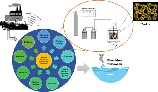
1. Introduction
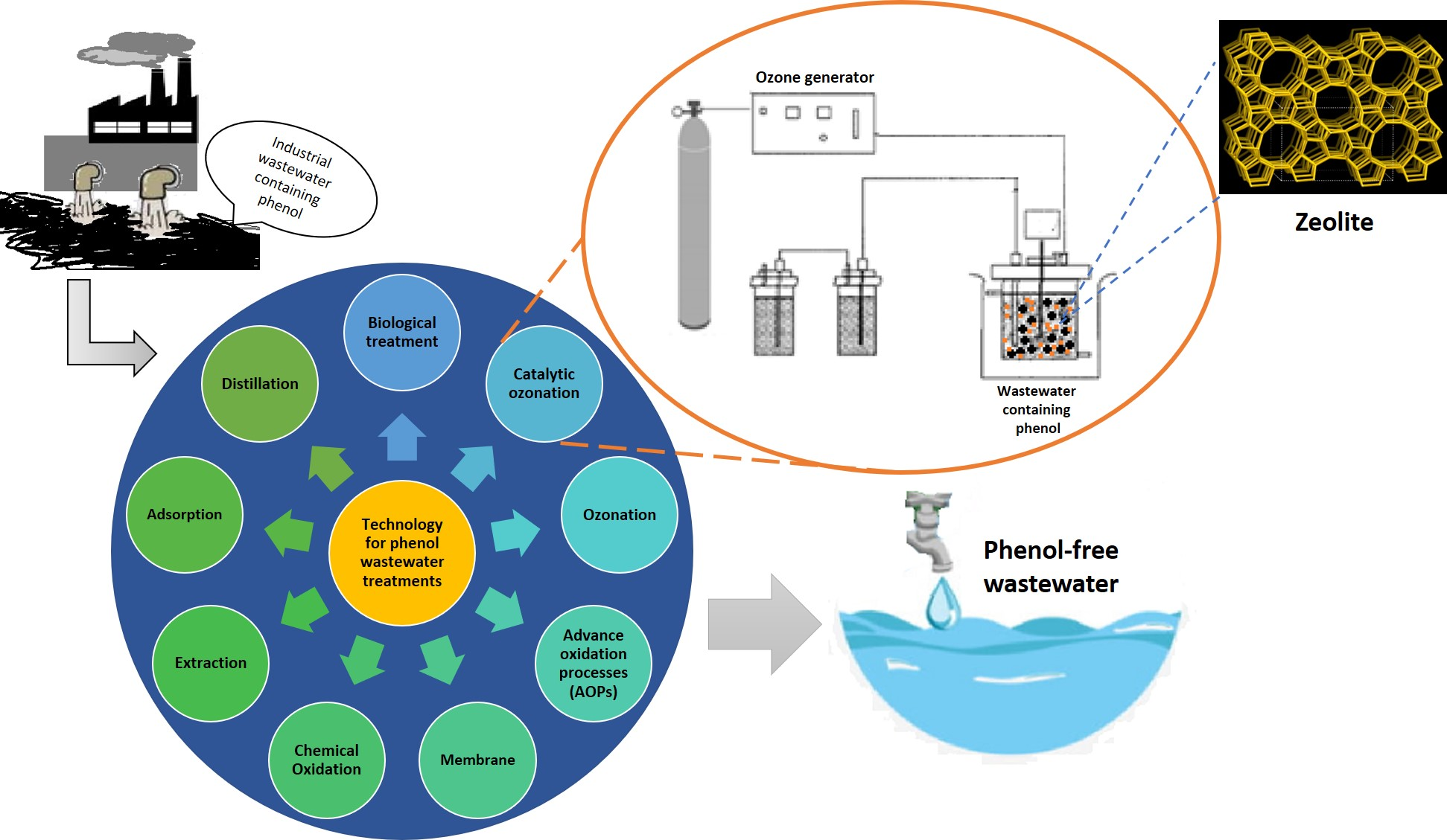
2. Phenol Compounds in Wastewater
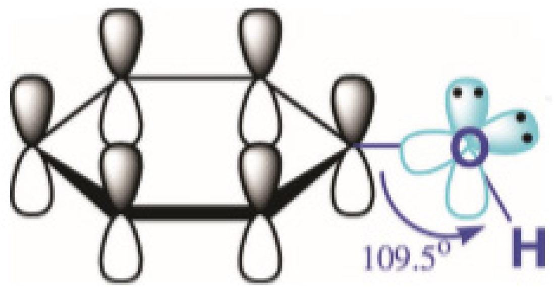
2.1. Chemical Structure and Properties of Phenol
2.2. Phenol Toxicity
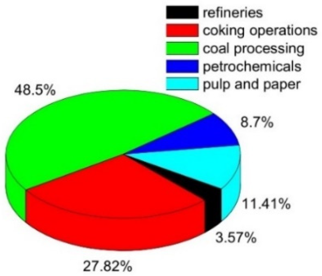
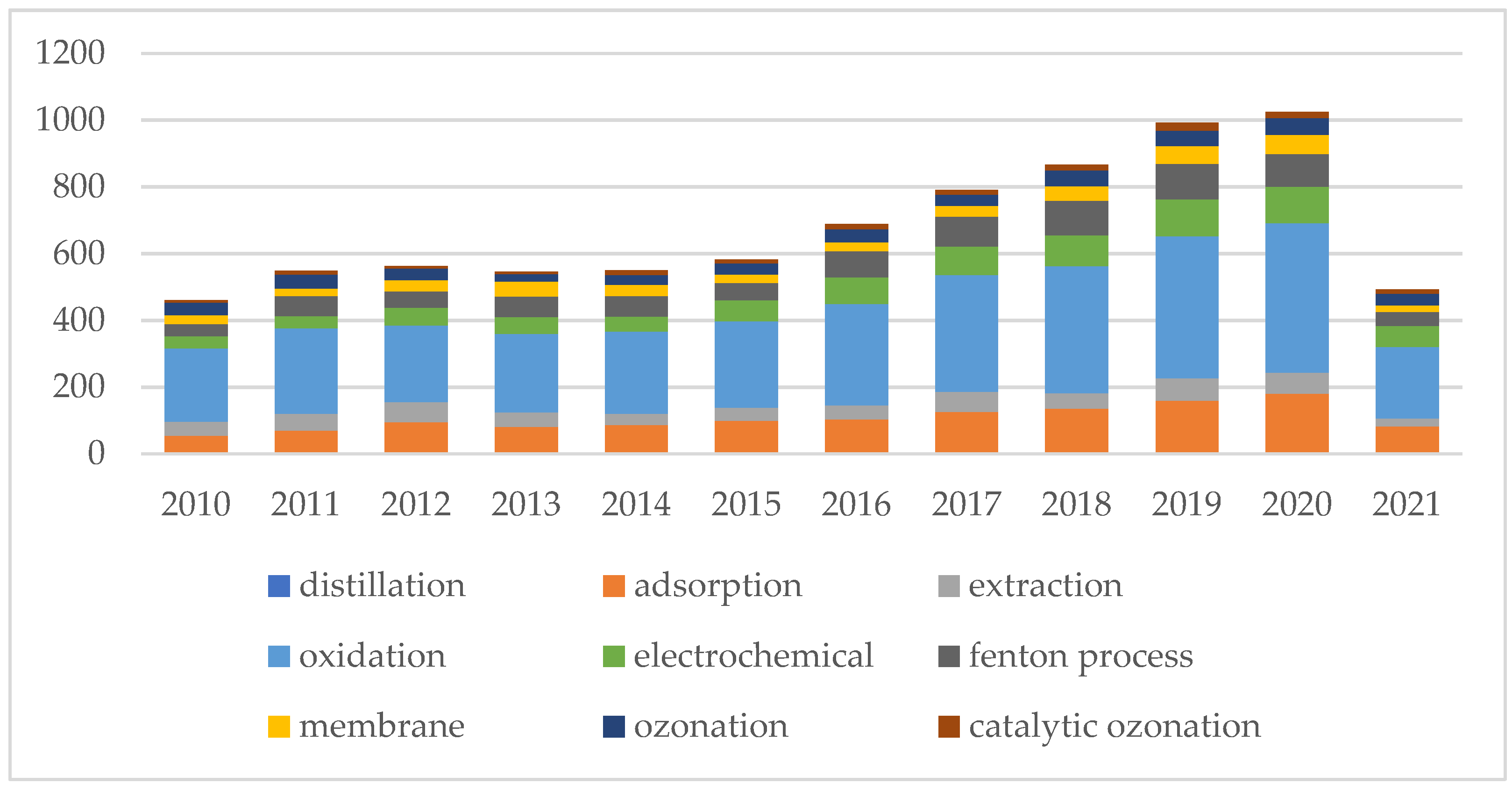
3. Development of Technologies for Phenol Treatment
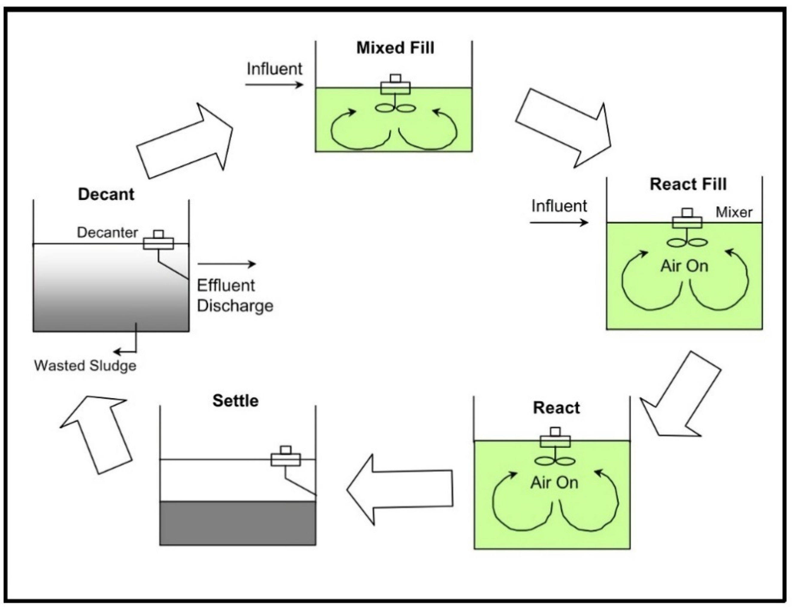
3.1. Biological Treatments
3.2. Conventional Technologies
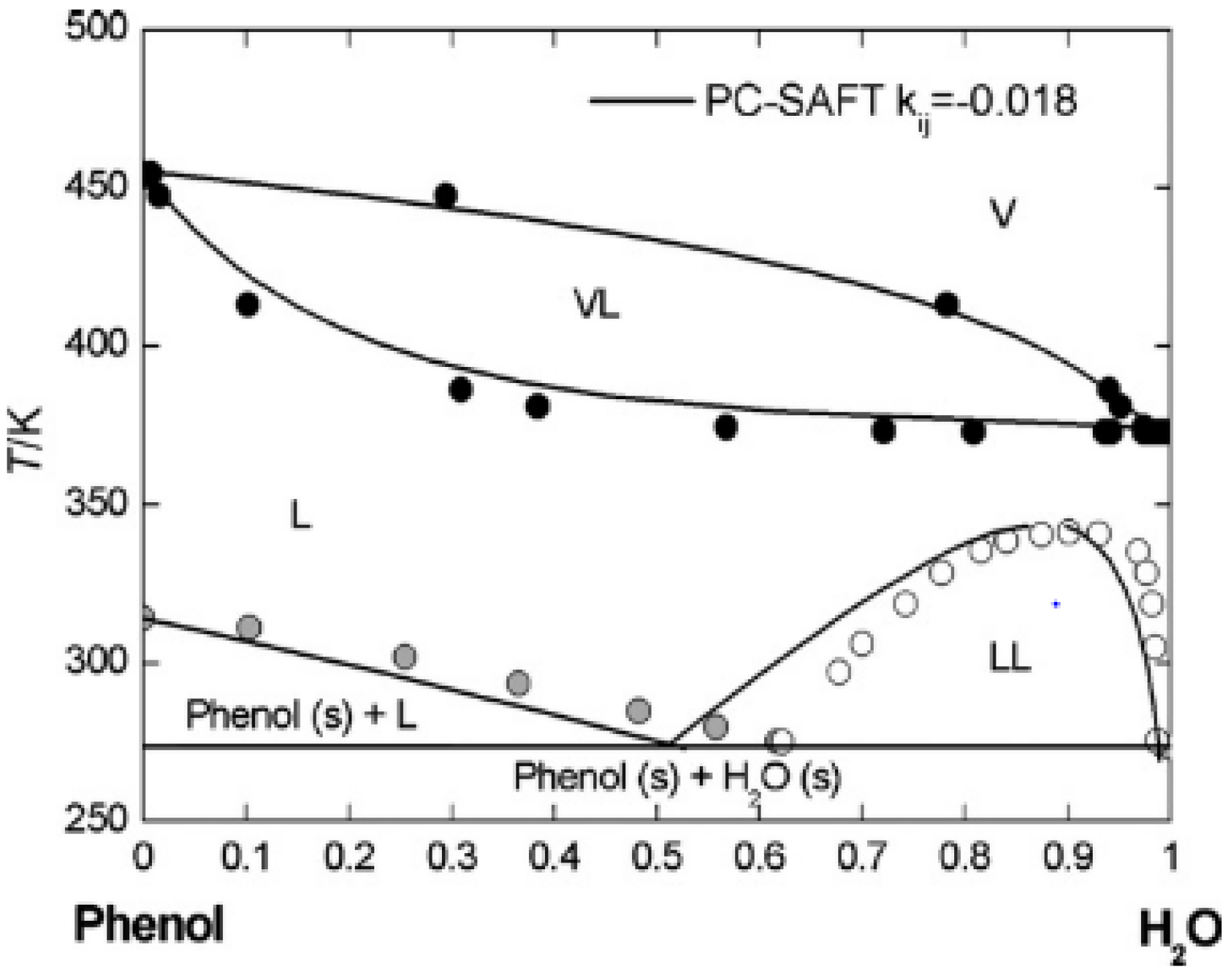
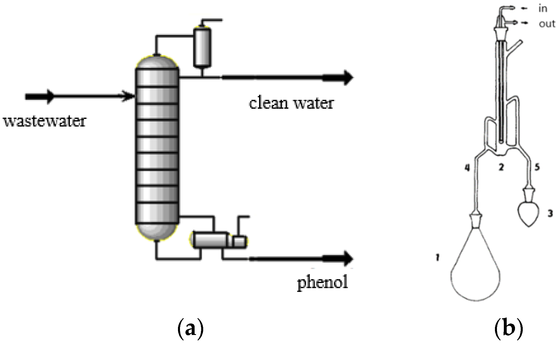
3.2.1. Steam Distillation
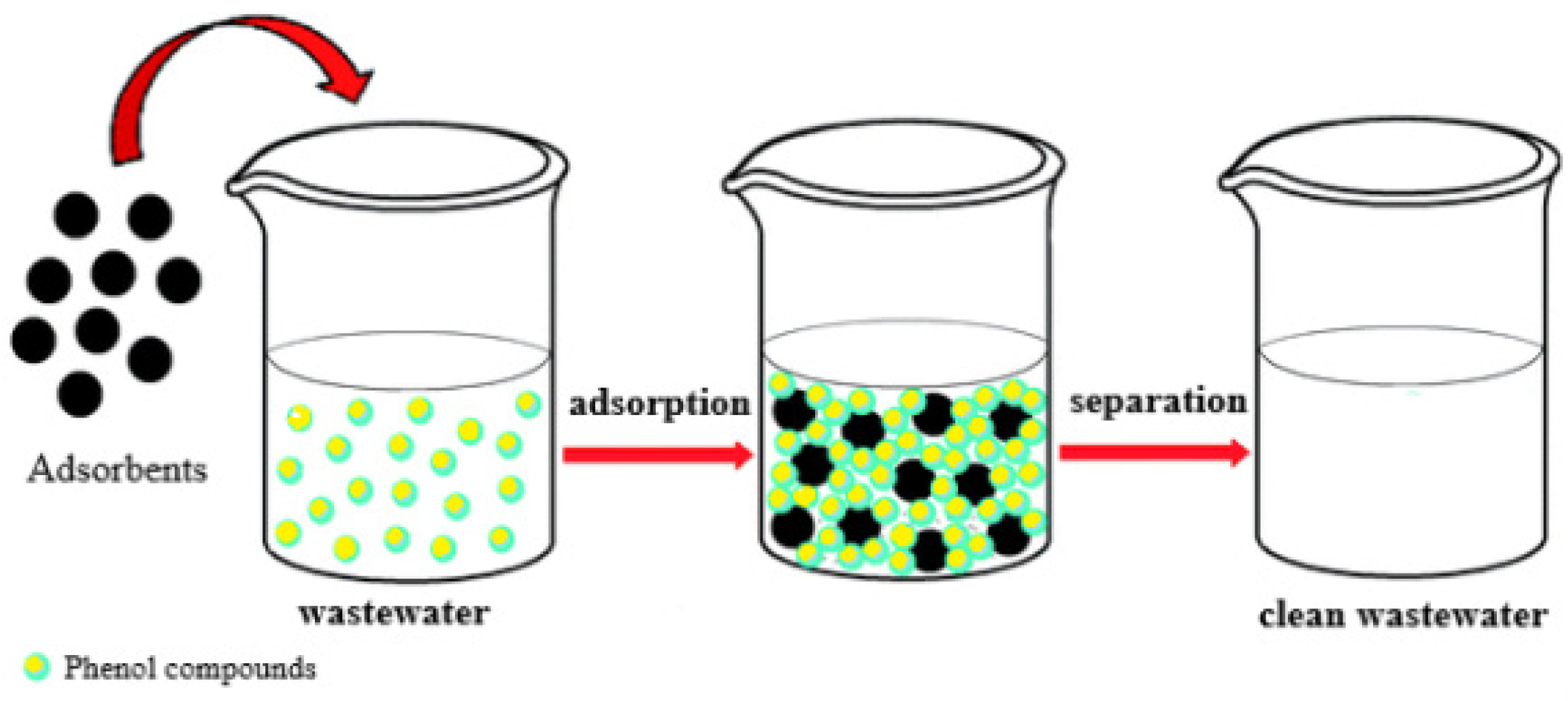
3.2.2. Adsorption
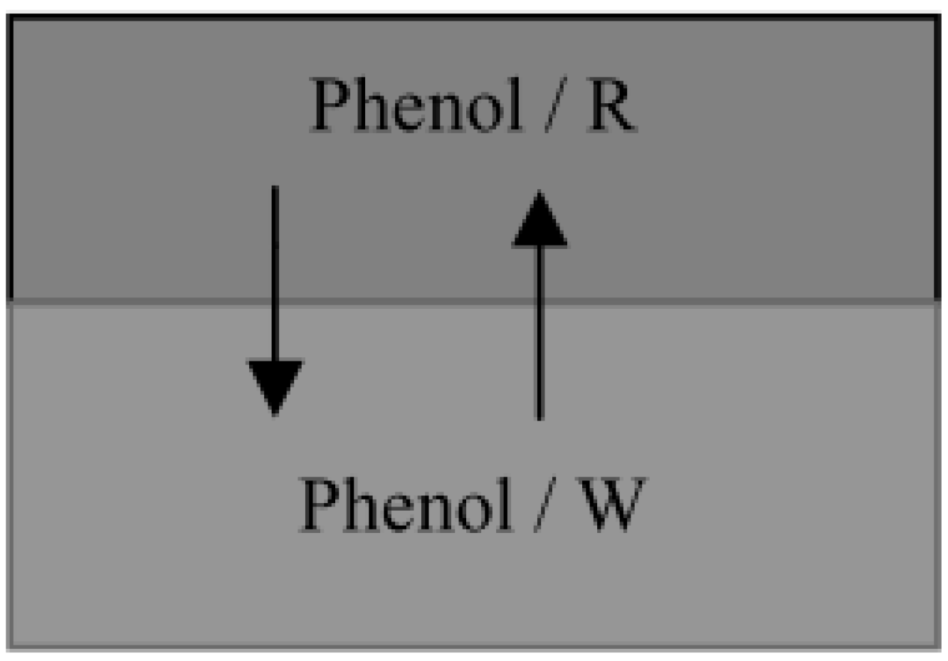
3.2.3. Liquid-Liquid Extraction
3.3. Advanced Technologies
3.3.1. Chemical Oxidation
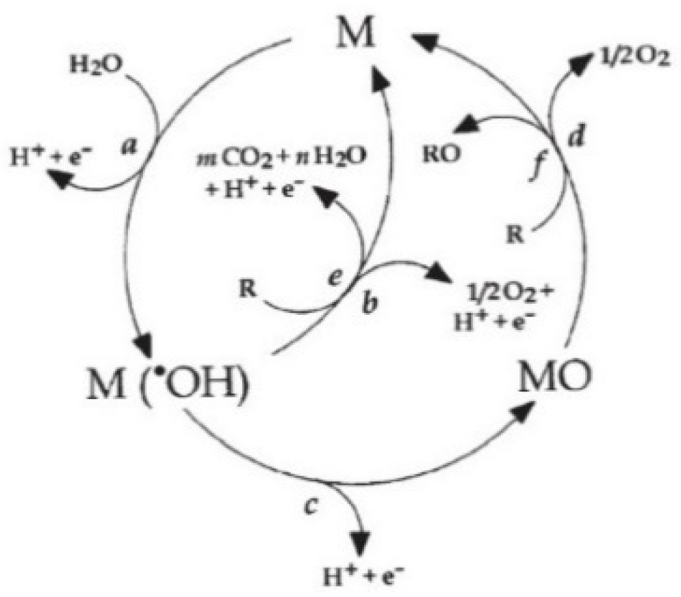
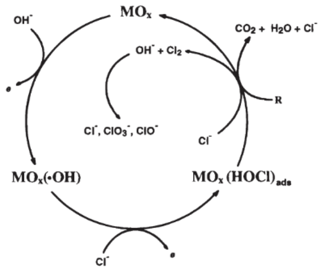
3.3.2. Electrochemical Oxidation
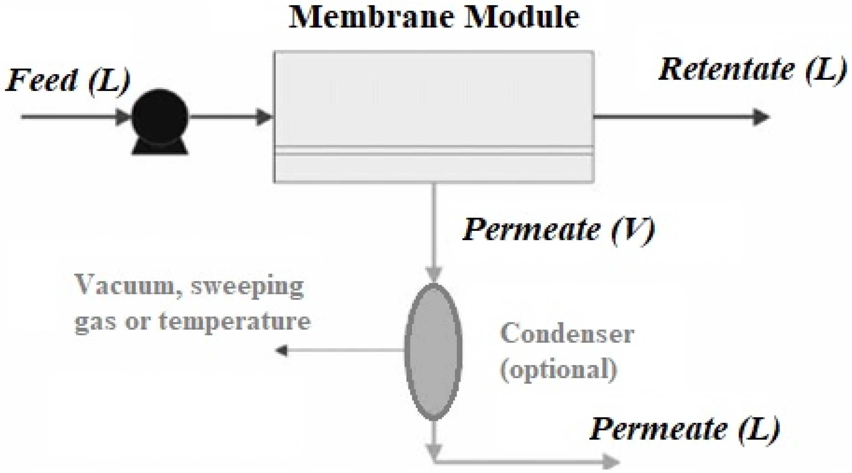
3.3.3. Membrane Process
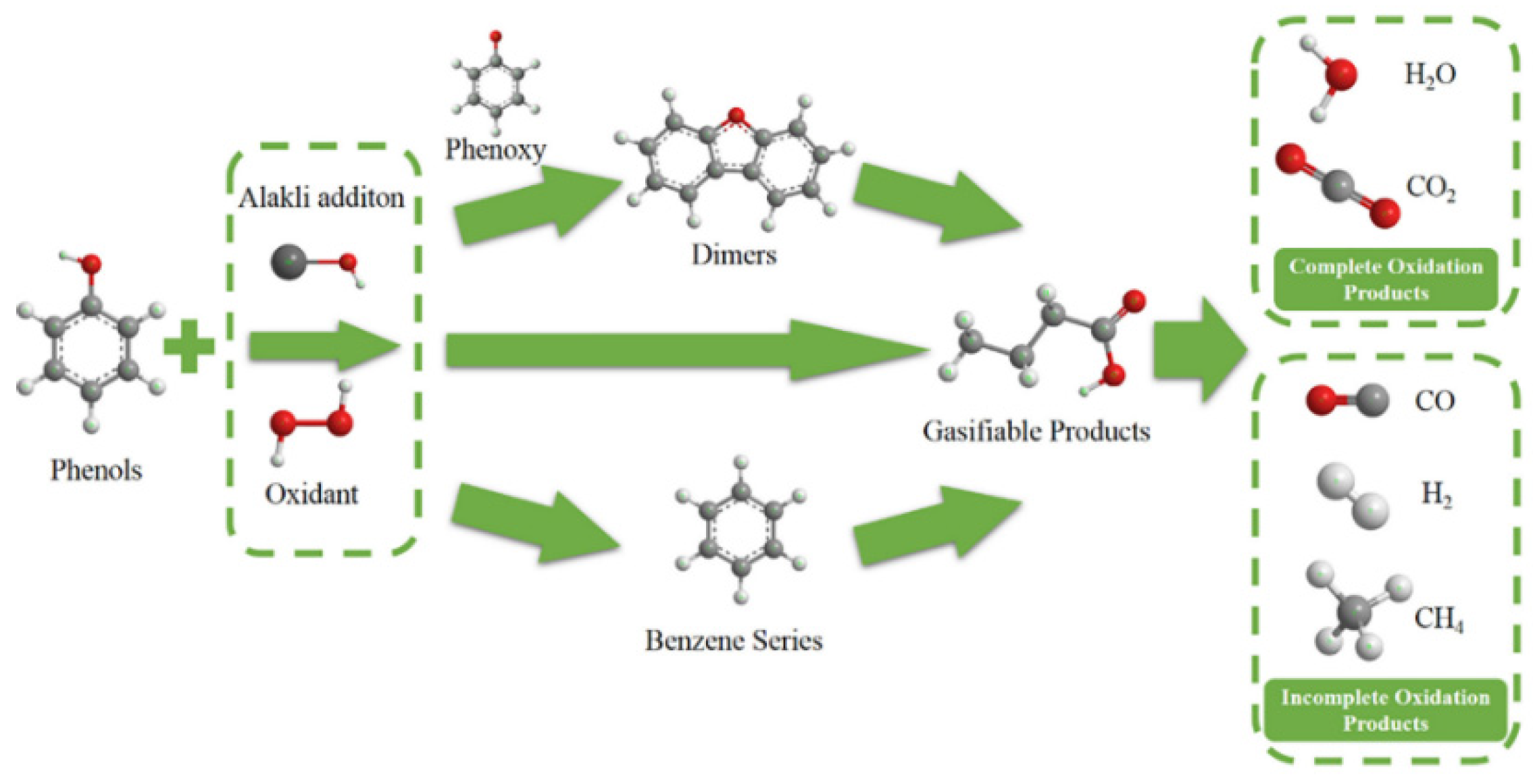
3.3.4. Supercritical Water Gasification
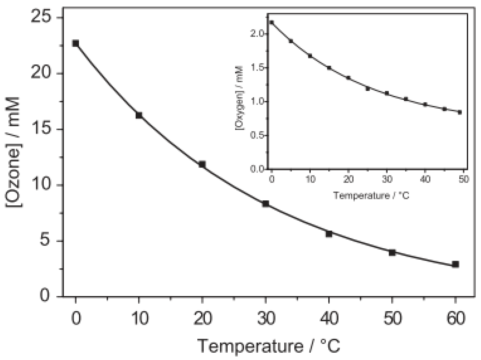
3.3.5. Ozonation
3.3.6. Advanced Oxidation Processes (AOPs)
O3/UV Process
O3/H2O2 Process
O3/Biological Treatment
Catalytic Ozonation
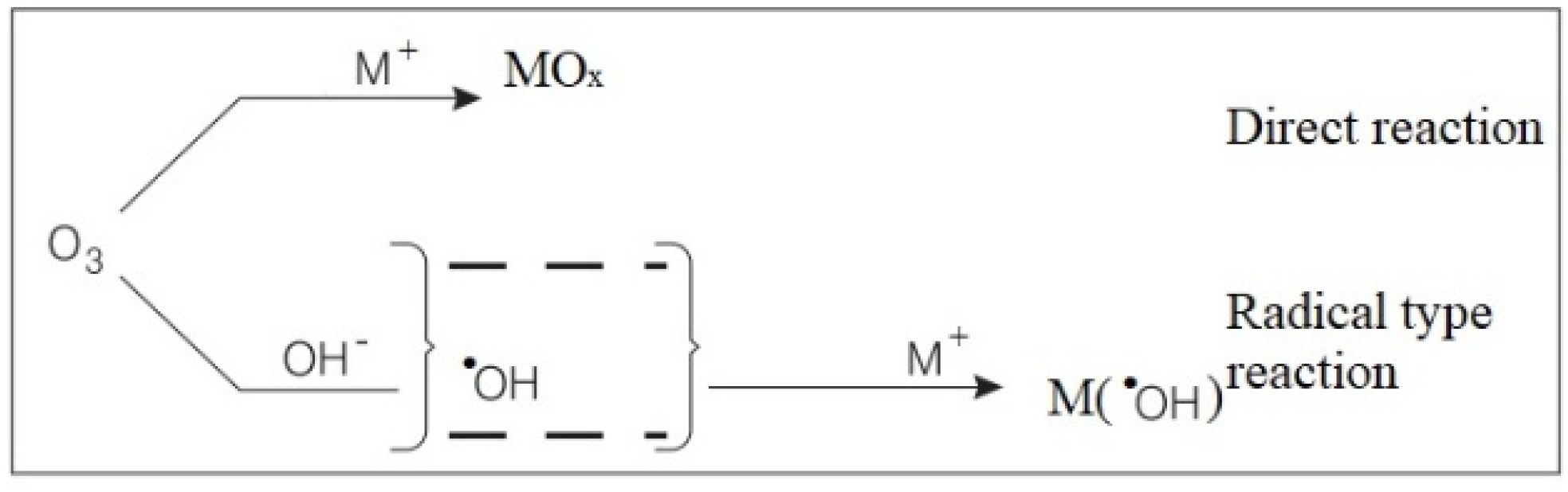
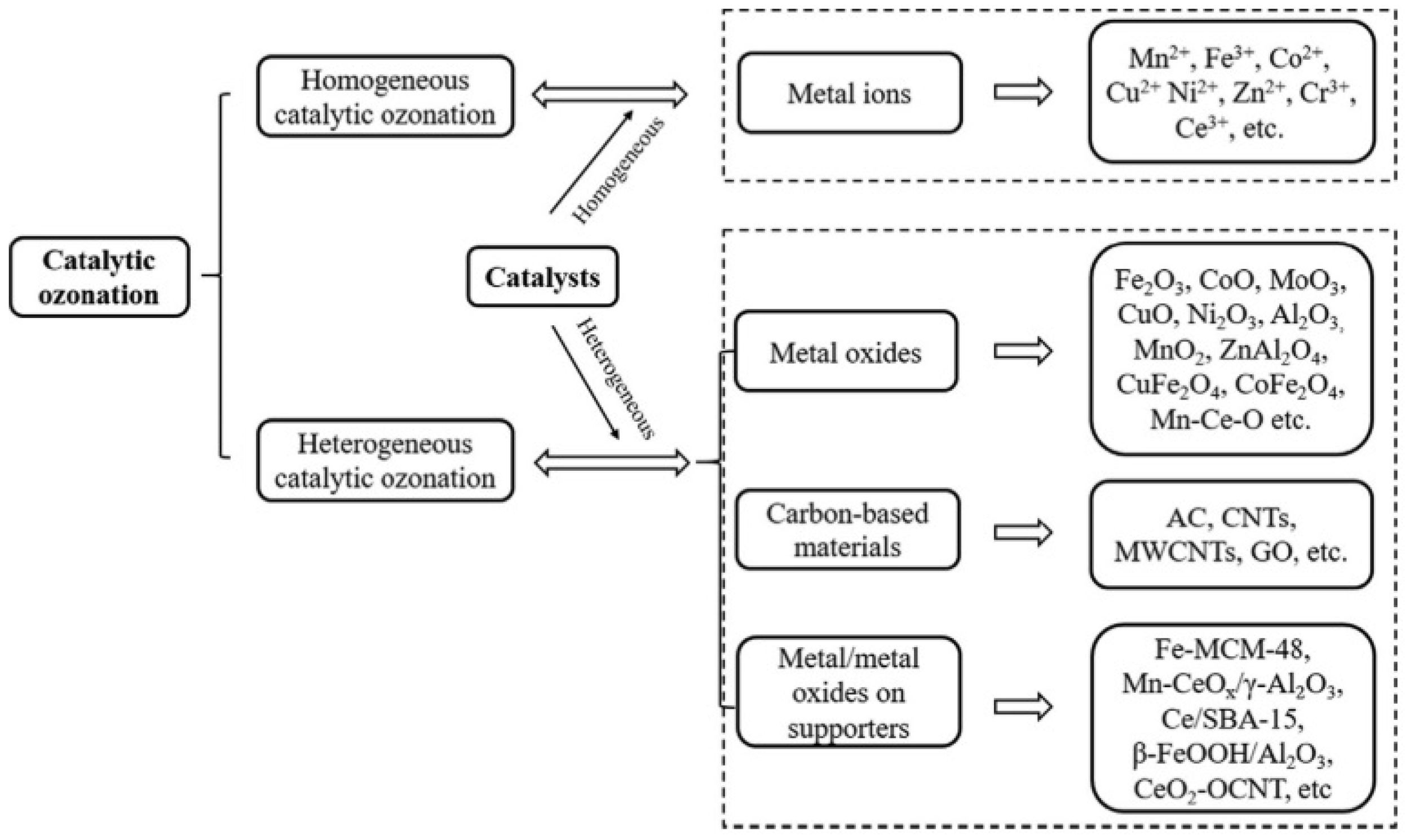
4. Catalytic Ozonation Mechanisms
4.1. Homogeneous Catalytic Ozonation
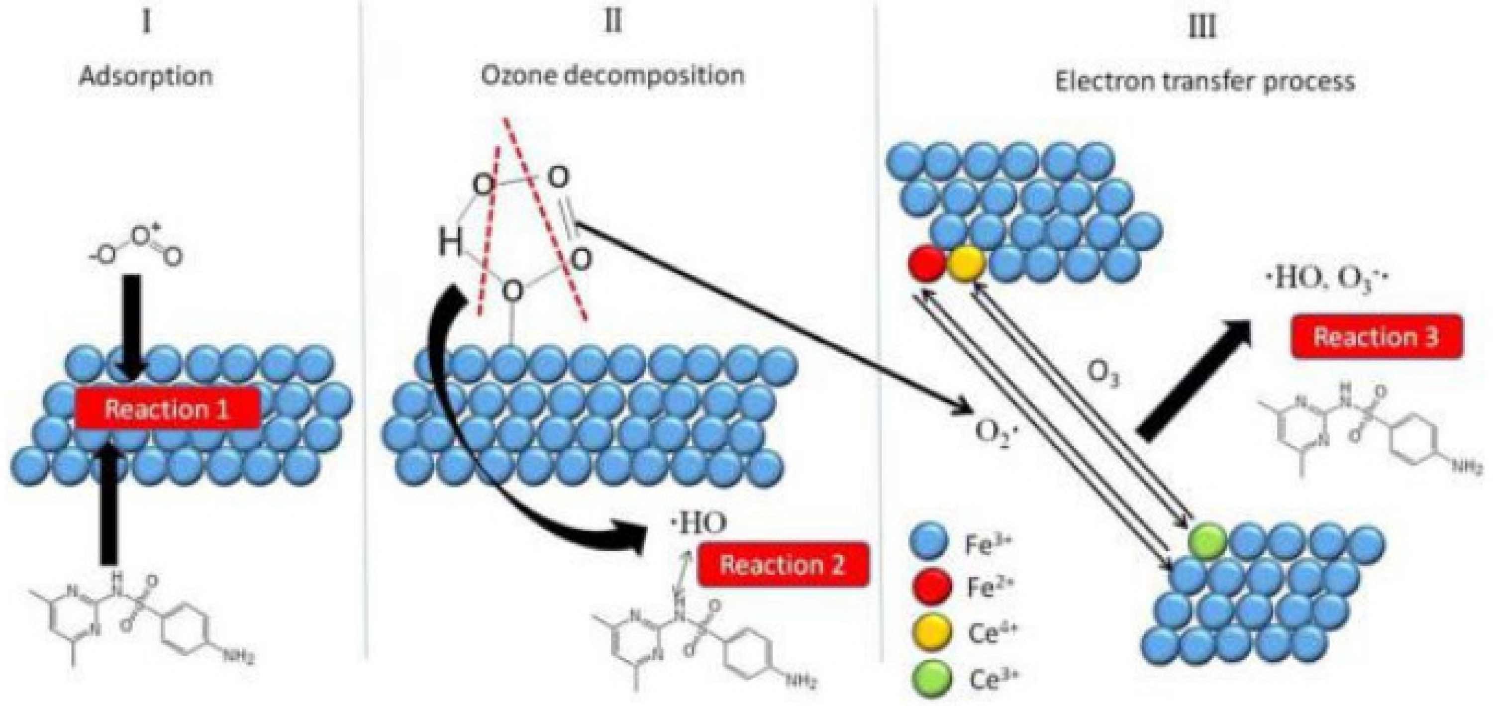
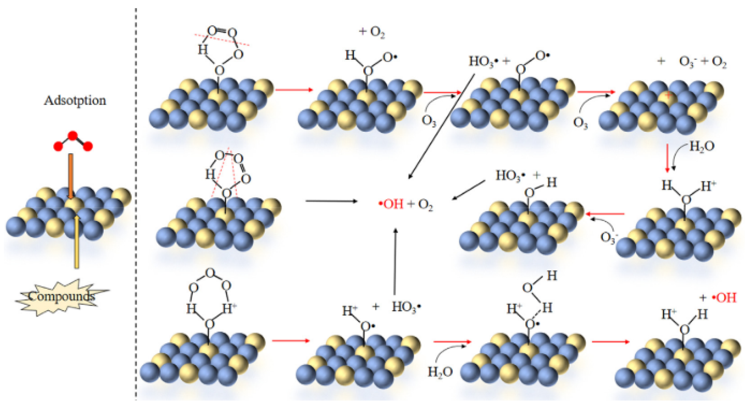
4.2. Heterogeneous Catalytic Ozonation
- Catalytic adsorption of O3 and organic compounds then reacted.
- Catalytic adsorption of O3 and then decomposed to produce free radicals, then the free radicals are reacted with organic compounds in bulk solution.
- Catalytic adsorption of organic compounds, then, is attacked by O3 molecules or other reactive oxygen species.
5. Development of Catalysts for Phenolic Compounds Removal via Heterogeneous Catalytic Ozonation
5.1. Metal-Based Catalyst
5.2. Metal Oxides-Based Catalysts
5.3. Metal/Metal Oxides on Support-Based Catalysts
5.4. Carbon-Based Catalysts
5.5. Mesoporous Catalysts
6. Zeolite as Heterogeneous Catalyst for Phenol Removal Using Heterogeneous Catalytic Ozonation Process
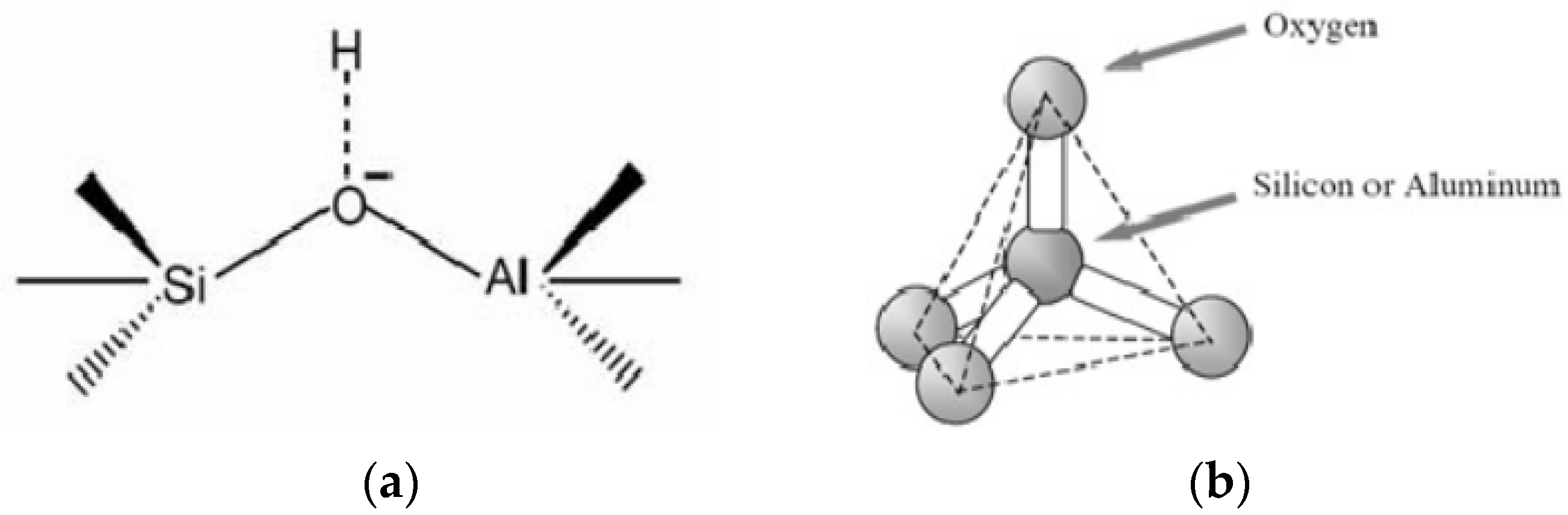
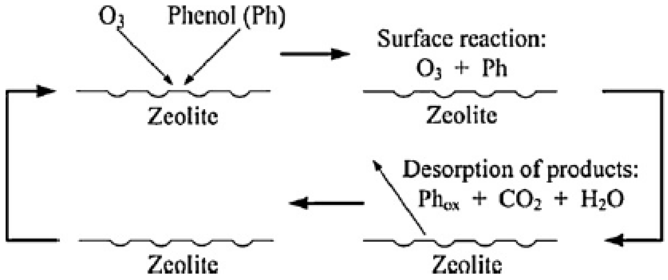
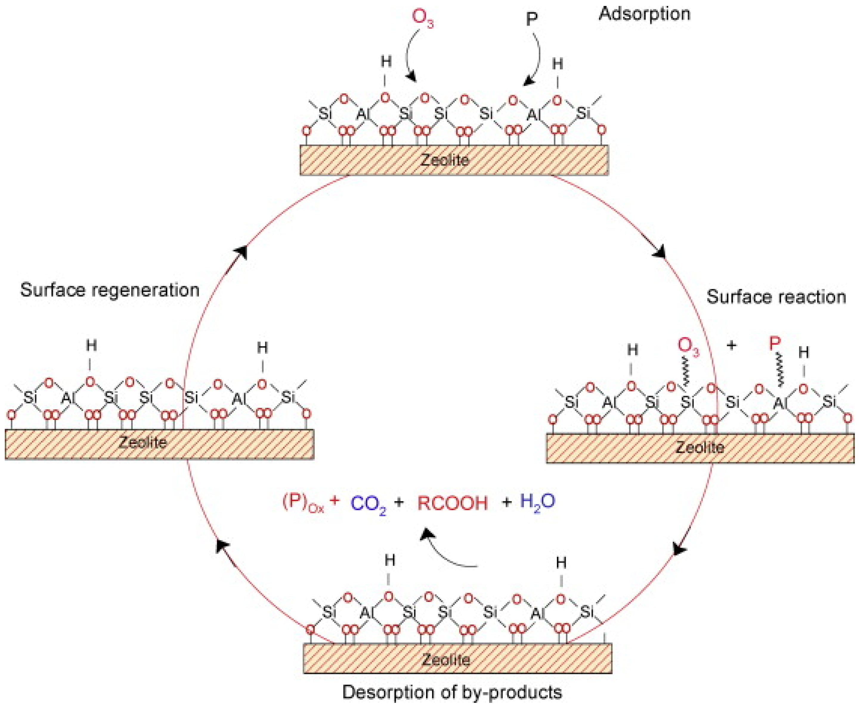
6.1. Zeolite Structures and General Mechanism of Phenol Removal Using Heterogeneous Catalytic Ozonation Process
6.2. Effect of Zeolite Characteristics on Phenol Removal Using Heterogeneous Catalytic Ozonation Process
6.3. Effect of Synthesis Method on Physiochemical Characteristics of Zeolite and Phenol Removal Using Heterogeneous Catalytic Ozonation Process
7. Summary and Outlook
- (i)
- Necessities of standardized performance evaluation.
- (ii)
- Development of zeolite-based catalyst for phenol removal
- (iii)
- Elucidation of active sites in zeolite-based catalyst
- (iv)
- Application of artificial intelligence (AI) for catalyst development
- (v)
- Techno-economic evaluation of heterogeneous catalytic ozonation
Author Contributions
Funding
Data Availability Statement
Acknowledgments
Conflicts of Interest
References
- International Water Association (IWA). The Wastewater Report 2017 Reuse Opportunity; IWA: London, UK, 2018; pp. 1–20. [Google Scholar]
- Calì, G.; Deiana, P.; Bassano, C.; Meloni, S.; Maggio, E.; Mascia, M.; Pettinau, A. Syngas Production, Clean-Up and Wastewater Management in a Demo-Scale Fixed-Bed Updraft Biomass Gasification Unit. Energies 2020, 13, 2594. [Google Scholar] [CrossRef]
- Raza, W.; Lee, J.; Raza, N.; Luo, Y.; Kim, K.-H.; Yang, J. Removal of phenolic compounds from industrial waste water based on membrane-based technologies. J. Ind. Eng. Chem. 2019, 71, 1–18. [Google Scholar] [CrossRef]
- Amin, N.A.S.; Akhtar, J.; Rai, H.K. Screening of combined zeolite-ozone system for phenol and COD removal. Chem. Eng. J. 2010, 158, 520–527. [Google Scholar] [CrossRef]
- Ma, J.; Chen, Y.; Nie, J.; Ma, L.; Huang, Y.; Li, L.; Liu, Y.; Guo, Z. Pilot-scale study on catalytic ozonation of bio-treated dyeing and finishing wastewater using recycled waste iron shavings as a catalyst. Sci. Rep. 2018, 8, 7555. [Google Scholar] [CrossRef] [PubMed]
- Dong, Y.; Wang, G.; Jiang, P.; Zhang, A.; Yue, L.; Zhang, X. Catalytic ozonation of phenol in aqueous solution by Co3O4 nanoparticles. Bull. Korean Chem. Soc. 2010, 31, 2830–2834. [Google Scholar] [CrossRef] [Green Version]
- Qu, X.; Zheng, J.; Zhang, Y. Catalytic ozonation of phenolic wastewater with activated carbon fiber in a fluid bed reactor. J. Colloid Interface Sci. 2007, 309, 429–434. [Google Scholar] [CrossRef]
- Kulkarni, S.J. Review on Research for Removal of Phenol from Wastewater. Int. J. Sci. Res. Publ. 2013, 3, 1–5. [Google Scholar]
- Polat, H.; Molva, M.; Polat, M. Capacity and mechanism of phenol adsorption on lignite. Int. J. Miner. Process. 2006, 79, 264–273. [Google Scholar] [CrossRef] [Green Version]
- Available online: https://scopus.com/term/analyzer (accessed on 3 May 2021).
- Ouyang, C.; Li, Y.; Li, J. The ZSM-5-Catalyzed Oxidation of Benzene to Phenol with N2O: Effect of Lewis Acid Sites. Catalysts 2019, 9, 44. [Google Scholar] [CrossRef] [Green Version]
- Sobiesiak, M. Chemical Structure of Phenols and Its Consequence for Sorption Processes. In Phenolic Compounds—Natural Sources, Importance and Applications; IntechOpen: London, UK, 2017. [Google Scholar] [CrossRef] [Green Version]
- Zhang, W.M.; Chen, J.L.; Pan, B.C.; Zhang, Q.X. Competitive and cooperative adsorption behaviors of phenol and aniline onto nonpolar macroreticular adsorbents. J. Environ. Sci. 2005, 17, 529–534. [Google Scholar]
- Mohammadi, S.; Kargari, A.; Sanaeepur, H.; Abbassian, K.; Najafi, A.; Mofarrah, E. Phenol removal from industrial wastewaters: A short review. Desalination Water Treat. 2015, 53, 2215–2234. [Google Scholar] [CrossRef]
- Villegas, L.G.C.; Mashhadi, N.; Chen, M.; Mukherjee, D.; Taylor, K.E.; Biswas, N. A Short Review of Techniques for Phenol Removal from Wastewater. Curr. Pollut. Rep. 2016, 2, 157–167. [Google Scholar] [CrossRef] [Green Version]
- Health Protection Agency (HPA). HPA Compendium of Chemical Hazards: Phenol Toxicological Overview; Public Health England: London, UK, 2007; pp. 1–12.
- Gami, A.A.; Shukor, M.Y.; Khalil, K.A.; Dahalan, F.A.; Khalid, A.; Ahmad, S.A. Phenol and its toxicity. J. Environ. Microbiol. Toxicol. 2014, 2, 11–24. [Google Scholar]
- Raghu, D.; Hsieh, H.N. Considerations in disposal of phenolic waters. Int. J. Environ. Stud. 2007, 30, 277–285. [Google Scholar] [CrossRef]
- Marrot, B.; Moulin, P.; Roche, N. Biodegradation of high phenol concentration by activated sludge in an immersed membrane bioreactor. Biochem. Eng. J. 2006, 30, 174–183. [Google Scholar] [CrossRef]
- Hussain, A.; Dubey, S.K.; Kumar, V. Kinetic study for aerobic treatment of phenolic wastewater. Water Resour. Ind. 2015, 11, 81–90. [Google Scholar] [CrossRef] [Green Version]
- Wang, L.K.; Pereira, N.C.; Hung, Y.-T.; Shammas, N.K. Biological Treatment Processes. Anaerob. Waste-Wastewater Treat. Biogas Plants 2018, 1–22. [Google Scholar] [CrossRef]
- Bevilaqua, J.V.; Cammarota, M.C.; Freire, D.M.G.; Sant’Anna, G.L., Jr. Phenol removal through combined biological and enzymatic treatments. Braz. J. Chem. Eng. 2002, 19, 151–158. [Google Scholar] [CrossRef]
- Jackson, T.; Lynn, M.; Giarrusso, S.; Urich, S.; Holland, R.; Eldredge, M. Wastewater Technology Fact Sheet Package Plants; Environmental Protection Agency (EPA): Washington, DC, USA, 2000.
- Busca, G.; Berardinelli, S.; Resini, C.; Arrighi, L. Technologies for the removal of phenol from fluid streams: A short review of recent developments. J. Hazard. Mater. 2008, 160, 265–288. [Google Scholar] [CrossRef] [PubMed]
- Chemat, F.; Boutekedjiret, C. Extraction//Steam Distillation. In Reference Module in Chemistry, Molecular Sciences and Chemical Engineering; Elsevier: Amsterdam, The Netherlands, 2015. [Google Scholar]
- Tumakaka, F.; Prikhodko, I.V.; Sadowski, G. Modeling of solid-liquid equilibria for systems with solid-complex phase formation. Fluid Phase Equilibria 2007, 260, 98–104. [Google Scholar] [CrossRef]
- Janda, V.; Krijt, K. Recovery of phenols from water by continuous steam distillation-extraction. J. Chromatogr. A 1984, 283, 309–314. [Google Scholar] [CrossRef]
- Norwitz, G.; Nataro, N.; Keliher, P.N. Study of the Steam Distillation of Phenolic Compounds Using Ultraviolet Spectrometry. Anal. Chem. 1986, 58, 639–641. [Google Scholar] [CrossRef]
- Norwitz, G.; Nataro, N.; Keliher, P.N. Steam distillation of phenolic compounds in the presence of a large amount of sodium chloride. Microchem. J. 1987, 35, 240–243. [Google Scholar] [CrossRef]
- Barták, P.; Frnková, P.; Čáp, L. Determination of phenols using simultaneous steam distillation-extraction. J. Chromatogr. A 2000, 867, 281–287. [Google Scholar] [CrossRef]
- Ali, I. The quest for active carbon adsorbent substitutes: Inexpensive adsorbents for toxic metal ions removal from wastewater. Sep. Purif. Rev. 2010, 39, 95–171. [Google Scholar] [CrossRef]
- Thang, P.Q.; Jitae, K.; Giang, B.L.; Viet, N.M.; Huong, P.T. Potential application of chicken manure biochar towards toxic phenol and 2,4-dinitrophenol in wastewaters. J. Environ. Manag. 2019, 251, 109556. [Google Scholar] [CrossRef]
- Mukherjee, R.; De, S. Adsorptive removal of phenolic compounds using cellulose acetate phthalate-alumina nanoparticle mixed matrix membrane. J. Hazard. Mater. 2014, 265, 8–19. [Google Scholar] [CrossRef]
- Rakic, V.; Rac, V.; Stosic, D. The investigation of phenol removal from aqueous solutions by zeolites as solid adsorbents. J. Hazard. Mater. 2010, 184, 477–484. [Google Scholar] [CrossRef]
- Alshabib, M.; Onaizi, S.A. A review on phenolic wastewater remediation using homogeneous and heterogeneous enzymatic processes: Current status and potential challenges. Sep. Purif. Technol. 2019, 219, 186–207. [Google Scholar] [CrossRef]
- Khalid, M.; Joly, G.; Renaud, A.; Magnoux, P. Removal of phenol from water by adsorption using zeolites. Ind. Eng. Chem. Res. 2004, 43, 5275–5280. [Google Scholar] [CrossRef]
- Ma, Y.; Gao, N.; Chu, W.; Li, C. Removal of phenol by powdered activated carbon adsorption. Front. Environ. Sci. Eng. 2013, 7, 158–165. [Google Scholar] [CrossRef]
- Mandal, A.; Das, S.K. Phenol adsorption from wastewater using clarified sludge from basic oxygen furnace. J. Environ. Chem. Eng. 2019, 7, 103259. [Google Scholar] [CrossRef]
- Catizzone, E.; Sposato, C.; Romanelli, A.; Barisano, D.; Cornacchia, G.; Marsico, L.; Cozza, D.; Migliori, M. Purification of Wastewater from Biomass-Derived Syngas Scrubber Using Biochar and Activated Carbons. Int. J. Environ. Res. Public Health 2021, 18, 4247. [Google Scholar] [CrossRef]
- Girish, C.R.; Murty, V.R. Adsorption of Phenol from Aqueous Solution Using Lantana camara, Forest Waste: Packed Bed Studies and Prediction of Breakthrough Curves. Environ. Process. 2015, 2, 773–796. [Google Scholar] [CrossRef] [Green Version]
- Tri, N.L.M.; Thang, P.Q.; Van Tan, L.; Huong, P.T.; Kim, J.; Viet, N.M.; Phuong, N.M.; Al Tahtamouni, T.M. Removal of phenolic compounds from wastewaters by using synthesized Fe-nano zeolite. J. Water Process Eng. 2020, 33, 101070. [Google Scholar] [CrossRef]
- Bin-Dahman, O.A.; Saleh, T.A. Synthesis of carbon nanotubes grafted with PEG and its efficiency for the removal of phenol from industrial wastewater. Environ. Nanotechnol. Monit. Manag. 2020, 13, 100286. [Google Scholar] [CrossRef]
- Rahmanian, N.; Jafari, S.M.; Galanakis, C.M. Recovery and removal of phenolic compounds from olive mill wastewater. JAOCS J. Am. Oil Chem. Soc. 2014, 91, 1–18. [Google Scholar] [CrossRef]
- Liu, J.; Xie, J.; Ren, Z.; Zhang, W. Solvent extraction of phenol with cumene from wastewater. Desalination Water Treat. 2013, 51, 3826–3831. [Google Scholar] [CrossRef]
- Jiang, H.; Fang, Y.; Fu, Y.; Guo, Q.X. Studies on the extraction of phenol in wastewater. J. Hazard. Mater. 2003, 101, 179–190. [Google Scholar] [CrossRef]
- Rao, N.N.; Singh, J.R.; Misra, R.; Nandy, T. Liquid-liquid extraction of phenol from simulated sebacic acid wastewater. J. Sci. Ind. Res. 2009, 68, 823–828. [Google Scholar]
- Marco, E.D.; Savarese, M.; Paduano, A.; Sacchi, R. Characterization and fractionation of phenolic compounds extracted from olive oil mill wastewaters. Food Chem. 2007, 104, 858–867. [Google Scholar] [CrossRef]
- Bouaziz, M.; Bouallagui, Z.; Jemai, H.; Sayadi, S. Production of antioxidants from olive processing by-products. J. Environ. Agric. Food Chem. 2008, 8, 3231–3236. [Google Scholar]
- Leonardis, A.D.; Macciola, V.; Lembo, G.; Aretini, A.; Nag, A. Food Chemistry Studies on oxidative stabilisation of lard by natural antioxidants recovered from olive-oil mill wastewater. Food Chem. 2007, 100, 998–1004. [Google Scholar] [CrossRef]
- Yang, C.; Qian, Y.; Zhang, L.; Feng, J. Solvent extraction process development and on-site trial-plant for phenol removal from industrial coal-gasification wastewater. Chem. Eng. J. 2006, 117, 179–185. [Google Scholar] [CrossRef]
- Yang, X.; Wang, B.; Luo, H.; Yan, S.; Dai, J.; Bai, Z. Efficient recovery of phenol from coal tar processing wastewater with tributylphosphane/diethyl carbonate/cyclohexane: Extraction cycle and mechanism study. Chem. Eng. Res. Des. 2020, 157, 104–113. [Google Scholar] [CrossRef]
- Rubalcaba, A.; Suarez-Ojeda, M.E.; Stuber, F.; Fortuny, A.; Bengoa, C. Phenol wastewater remediation: Advanced oxidation processes coupled to a biological treatment. Water Sci. Technol. 2007, 55, 221–227. [Google Scholar] [CrossRef]
- Chamberlin, A.N.S.; Griffin, A.E.; Pettit, G.A.; Sewage, S.; Wastes, I.; Jun, N.; Wastes, I.; Griffin, E. Chemical Oxidation of Phenolic Wastes with Chlorine. Water Environ. Fed. 2014, 24, 750–763. [Google Scholar]
- Eisenhauer, H.R. Oxidation of phenolic wastes. Water Pollut. Control. Fed. 2015, 36, 1116–1128. [Google Scholar]
- Chen, L.; Ma, J.; Li, X.; Zhang, J.; Fang, J.; Guan, Y.; Xie, P. Strong enhancement on Fenton oxidation by addition of hydroxylamine to accelerate the ferric and ferrous iron cycles. Environ. Sci. Technol. 2011, 45, 3925–3930. [Google Scholar] [CrossRef]
- Wang, N.; Zheng, T.; Zhang, G.; Wang, P. A review on Fenton-like processes for organic wastewater treatment. J. Environ. Chem. Eng. 2016, 4, 762–787. [Google Scholar] [CrossRef] [Green Version]
- Zhang, M.H.; Dong, H.; Zhao, L.; Wang, D.X.; Meng, D. A review on Fenton process for organic wastewater treatment based on optimization perspective. Sci. Total. Environ. 2019, 670, 110–121. [Google Scholar] [CrossRef]
- Pigot, T.; Peings, V. Mechanism for the oxidation of phenol by sulfatoferrate (VI): Comparison with various oxidants. J. Environ. Manag. 2015, 157, 287–296. [Google Scholar] [CrossRef]
- Zhang, J.; Sun, B.; Guan, X. Oxidative removal of bisphenol A by permanganate: Kinetics, pathways and influences of co-existing chemicals. Sep. Purif. Technol. 2013, 107, 48–53. [Google Scholar] [CrossRef]
- Martínez-Huitle, C.A.; Ferro, S. Electrochemical oxidation of organic pollutants for the wastewater treatment: Direct and indirect processes. Chem. Soc. Rev. 2006, 35, 1324–1340. [Google Scholar] [CrossRef] [PubMed]
- Tasic, Z.; Gupta, V.K.; Antonijevic, M.M. The mechanism and kinetics of degradation of phenolics in wastewaters using electrochemical oxidation. Int. J. Electrochem. Sci. 2014, 9, 3473–3490. [Google Scholar]
- Saratale, R.G.; Hwang, K.J.; Song, J.Y.; Saratale, G.D.; Kim, D.S. Electrochemical oxidation of phenol for wastewater treatment using Ti/PbO2 electrode. J. Environ. Eng. 2016, 142, 04015064. [Google Scholar] [CrossRef]
- Duan, X.; Ma, F.; Yuan, Z.; Jin, X.; Chang, L. Electrochemical degradation of phenol in aqueous solution using PbO2 anode. J. Taiwan Inst. Chem. Eng. 2013, 44, 95–102. [Google Scholar] [CrossRef]
- Li, H.; Chen, Y.; Zhang, Y.; Han, W.; Sun, X.; Li, J.; Wang, L. Preparation of Ti/PbO2-Sn anodes for electrochemical degradation of phenol. J. Electroanal. Chem. 2013, 689, 193–200. [Google Scholar] [CrossRef]
- Song, S.; Zhan, L.; He, Z.; Lin, L.; Tu, J.; Zhang, Z.; Chen, J.; Xu, L. Mechanism of the anodic oxidation of 4-chloro-3-methyl phenol in aqueous solution using Ti/SnO2-Sb/PbO2 electrodes. J. Hazard. Mater. 2010, 175, 614–621. [Google Scholar] [CrossRef]
- Kumar, S.; Singh, S.; Srivastava, V.C. Electro-oxidation of nitrophenol by ruthenium oxide coated titanium electrode: Parametric, kinetic and mechanistic study. Chem. Eng. J. 2015, 263, 135–143. [Google Scholar] [CrossRef]
- Kong, J.T.; Shi, S.Y.; Zhu, X.P.; Ni, J.R. Effect of Sb dopant amount on the structure and electrocatalytic capability of Ti/Sb-SnO2 electrodes in the oxidation of 4-chlorophenol. J. Environ. Sci. 2007, 19, 1380–1386. [Google Scholar] [CrossRef]
- Yang, X.; Zou, R.; Huo, F.; Cai, D.; Xiao, D. Preparation and characterization of Ti/SnO2-Sb2O3-Nb2O5/PbO2 thin film as electrode material for the degradation of phenol. J. Hazard. Mater. 2009, 164, 367–373. [Google Scholar] [CrossRef]
- Wang, Y.; Shen, Z.; Li, Y.; Niu, J. Electrochemical properties of the erbium-chitosan-fluorine-modified PbO2 electrode for the degradation of 2,4-dichlorophenol in aqueous solution. Chemosphere 2010, 79, 987–996. [Google Scholar] [CrossRef] [PubMed]
- Zhao, T.; Lu, J.; Hu, C.; Zhu, C.; Zhao, J.; Dong, W. Electrochemical degradation of 4, 4′-(propane-2, 2-diyl) diphenol in water with CeO2/β-PbO2/Ti electrode. Int. J. Electrochem. Sci. 2014, 9, 2354–2366. [Google Scholar]
- Bolong, N.; Ismail, A.F.; Salim, M.R.; Matsuura, T. A review of the effects of emerging contaminants in wastewater and options for their removal. Desalination 2009, 239, 229–246. [Google Scholar] [CrossRef]
- Ren, L.F.; Chen, R.; Zhang, X.; Shao, J.; He, Y. Phenol biodegradation and microbial community dynamics in extractive membrane bioreactor (EMBR) for phenol-laden saline wastewater. Bioresour. Technol. 2017, 244, 1121–1128. [Google Scholar] [CrossRef] [PubMed]
- Slater, C.S.; Schurmann, T.; MacMillian, J.; Zimarowski, A. Separation of diacteone alcohol-water mixtures by membrane pervaporation. Sep. Sci. Technol. 2006, 41, 2733–2753. [Google Scholar] [CrossRef]
- Li, J.; Wu, J.; Sun, H.; Cheng, F.; Liu, Y. Advanced treatment of biologically treated coking wastewater by membrane distillation coupled with pre-coagulation. Desalination 2016, 380, 43–51. [Google Scholar] [CrossRef]
- Ng, Y.S.; Jayakumar, N.S.; Hashim, M.A. Performance evaluation of organic emulsion liquid membrane on phenol removal. J. Hazard. Mater. 2010, 184, 255–260. [Google Scholar] [CrossRef] [Green Version]
- Boonnorat, J.; Chiemchaisri, C.; Chiemchaisri, W.; Yamamoto, K. Removals of phenolic compounds and phthalic acid esters in landfill leachate by microbial sludge of two-stage membrane bioreactor. J. Hazard. Mater. 2014, 277, 93–101. [Google Scholar] [CrossRef] [Green Version]
- Ghaemi, N.; Madaeni, S.S.; Alizadeh, A.; Daraei, P.; Badieh, M.M.S.; Falsafi, M.; Vatanpour, V. Fabrication and modification of polysulfone nanofiltration membrane using organic acids: Morphology, characterization and performance in removal of xenobiotics. Sep. Purif. Technol. 2012, 96, 214–228. [Google Scholar] [CrossRef]
- Li, Y.; Wei, J.; Wang, C.; Wang, W. Comparison of phenol removal in synthetic wastewater by NF or RO membranes. Desalination Water Treat. 2010, 22, 211–219. [Google Scholar] [CrossRef]
- Praveen, P.; Loh, K.C. Osmotic membrane bioreactor for phenol biodegradation under continuous operation. J. Hazard. Mater. 2016, 305, 115–122. [Google Scholar] [CrossRef] [PubMed]
- Casademont, P.; García-Jarana, M.B.; Sánchez-Oneto, J.; Portela, J.R.; de la Ossa, E.J.M. Supercritical water gasification: A patents review. Reviews in Chemical Engineering 2017, 33, 237–261. [Google Scholar] [CrossRef]
- Yakaboylu, O.; Harinck, J.; Smit, K.G.; De Jong, W. Supercritical Water Gasification of Biomass: A Literature and Technology Overview. Energies 2015, 8, 859–894. [Google Scholar] [CrossRef]
- DiLeo, G.J.; Neff, M.E.; Kim, S.; Savage, P.E. Supercritical Water Gasification of Phenol and Glycine as Models for Plant and Protein Biomass. Energy Fuels 2008, 22, 871–877. [Google Scholar] [CrossRef]
- Castello, D.; Kruse, A.; Fiori, L. Supercritical water gasification of glucose/phenol mixtures as model compounds for ligno-cellulosic biomass. Chem. Eng. Trans. 2014, 37, 193–198. [Google Scholar]
- Guan, Q.; Wei, C.; Shi, H.; Wu, C.; Chai, X.-S. Partial oxidative gasification of phenol for hydrogen in supercritical water. Appl. Energy 2011, 88, 2612–2616. [Google Scholar] [CrossRef]
- Kruse, A. Supercritical water gasification. Biofuels Bioprod. Biorefining 2008, 2, 415–437. [Google Scholar] [CrossRef]
- Zhang, H.; Zhang, X.; Ding, L. Partial oxidation of phenol in supercritical water with NaOH and H2O2: Hydrogen production and polymer formation. Sci. Total. Environ. 2020, 722, 137985. [Google Scholar] [CrossRef]
- Xu, D.; Wang, S.; Guo, Y.; Tang, X.; Gong, Y.; Ma, H. Catalyzed Partial Oxidative Gasification of Phenol in Supercritical Water. Ind. Eng. Chem. Res. 2011, 50, 4301–4307. [Google Scholar] [CrossRef]
- Forero, J.E.; Duque, J.J.; Rios, F.; Díaz, J. Ozone for phenol treatment in industrial wastewater. CT F Cienc. Tecnol. Y Futuro 2001, 2, 17–26. [Google Scholar]
- Wang, J.; Chen, H. Catalytic ozonation for water and wastewater treatment: Recent advances and perspective. Sci. Total. Environ. 2020, 704, 135249. [Google Scholar] [CrossRef] [PubMed]
- Von Sonntag, C.; von Gunten, U. Chemistry of Ozone in Water and Wastewater Treatment: From Basic Principles to Applications; IWA Publishing: London, UK, 2012. [Google Scholar]
- Kasprzyk-Hordern, B.; Ziółek, M.; Nawrocki, J. Catalytic ozonation and methods of enhancing molecular ozone reactions in water treatment. Appl. Catal. B Environ. 2003, 46, 639–669. [Google Scholar] [CrossRef]
- Wei, C.; Zhang, F.; Hu, Y.; Feng, C.; Wu, H. Ozonation in water treatment: The generation, basic properties of ozone and its practical application. Rev. Chem. Eng. 2017, 33, 49–89. [Google Scholar] [CrossRef]
- Hoigné, J. Chemistry of Aqueous Ozone and Transformation of Pollutants by Ozonation and Advanced Oxidation Processes. Handb. Environ. Chem. 1998, 5, 83–141. [Google Scholar] [CrossRef]
- Sano, N.; Yamamoto, T.; Yamamoto, D.; Kim, S.I.; Eiad-Ua, A.; Shinomiya, H.; Nakaiwa, M. Degradation of aqueous phenol by simultaneous use of ozone with silica-gel and zeolite. Chem. Eng. Process. Process Intensif. 2007, 46, 513–519. [Google Scholar] [CrossRef]
- Haag, W.R.; Holgné, J. Ozonation of Bromide-Containing Waters: Kinetics of Formation of Hypobromous Acid and Brómate. Environ. Sci. Technol. 1983, 17, 261–267. [Google Scholar] [CrossRef]
- Turhan, K.; Uzman, S. Removal of phenol from water using ozone. Desalination 2008, 229, 257–263. [Google Scholar] [CrossRef]
- Wahyudi, D.P.; Ghaisani, S.V.; Bismo, S. Degradation of phenol and 2,4-dichlorophenol wastewater by ozonation in multi-injection bubble column reactor. J. Phys. Conf. Ser. 2019, 1349, 012074. [Google Scholar] [CrossRef] [Green Version]
- Zeng, Z.; Zou, H.; Li, X.; Arowo, M.; Sun, B.; Chen, J.; Chu, G.; Shao, L. Degradation of phenol by ozone in the presence of Fenton reagent in a rotating packed bed. Chem. Eng. J. 2013, 229, 404–411. [Google Scholar] [CrossRef]
- Karamah, E.F.; Leonita, S.; Bismo, S. Phenols removal using ozonation-adsorption with granular activated carbon (GAC) in rotating packed bed reactor. IOP Conf. Ser. Mater. Sci. Eng. 2018, 299, 012094. [Google Scholar] [CrossRef]
- Cheng, W.; Quan, X.; Li, R.; Wu, J.; Zhao, Q. Ozonation of Phenol-Containing Wastewater Using O3/Ca(OH)2 System in a Micro Bubble Gas-Liquid Reactor. Ozone Sci. Eng. 2018, 40, 173–182. [Google Scholar] [CrossRef]
- Suzuki, H.; Araki, S.; Yamamoto, H. Evaluation of advanced oxidation processes (AOP) using O3, UV, and TiO2 for the degradation of phenol in water. J. Water Process Eng. 2015, 7, 54–60. [Google Scholar] [CrossRef]
- Drijvers, D.; Langenhove, H.V.A.N.; Beckers, M. Decomposition of phenol and trichloroethylene by the ultrasound/H2O2/CuO process. Water Res. 1999, 33, 1187–1194. [Google Scholar] [CrossRef]
- Kidak, R.; Ince, N.H. Catalysis of advanced oxidation reactions by ultrasound: A case study with phenol. J. Hazard. Mater. 2007, 146, 630–635. [Google Scholar] [CrossRef]
- Entezari, M.H.; Christian, P. Sonochemical degradation of phenol in water: A comparison of classical equipment with a new cylindrical reactor. Ultrason. Sonochem. 2003, 10, 103–108. [Google Scholar] [CrossRef]
- Primo, O.; Rivero, J.; Ortiz, I.; Irabien, A. Mathematical modelling of phenol photooxidation: Kinetics of the process toxicity. Chem. Eng. J. 2007, 134, 23–28. [Google Scholar] [CrossRef]
- Paucar, N.E.; Kim, I.; Tanaka, H.; Sato, C. Effect of O3 Dose on the O3/UV Treatment Process for the Removal of Pharmaceuticals and Personal Care Products in Secondary Effluent. ChemEngineering 2019, 3, 53. [Google Scholar] [CrossRef] [Green Version]
- Saputera, W.H.; Scott, J.; Tahini, H.; Low, G.K.C.; Tan, X.; Smith, S.; Wang, D.-W.; Amal, R. Light, Catalyst, Activation: Boosting Catalytic Oxygen Activation Using a Light Pretreatment Approach. ACS Catal. 2017, 7, 3644–3653. [Google Scholar] [CrossRef]
- Saputera, W.H.; Tahini, H.A.; Lovell, E.C.; Tan, T.H.; Rawal, A.; Aguey-Zinsou, K.-F.; Friedmann, D.; Smith, S.C.; Amal, R.; Scott, J. Cooperative defect-enriched SiO2 for oxygen activation and organic dehydrogenation. J. Catal. 2019, 376, 168–179. [Google Scholar] [CrossRef]
- Saputera, W.H.; Tahini, H.A.; Sabsabi, M.; Tan, T.H.; Bedford, N.M.; Lovell, E.; Cui, Y.; Hart, J.N.; Friedmann, D.; Smith, S.C.; et al. Light-Induced Synergistic Multidefect Sites on TiO2/SiO2 Composites for Catalytic Dehydrogenation. ACS Catal. 2019, 9, 2674–2684. [Google Scholar] [CrossRef]
- Hamdy, M.S.; Saputera, W.H.; Groenen, E.J.; Mul, G. A novel TiO2 composite for photocatalytic wastewater treatment. J. Catal. 2014, 310, 75–83. [Google Scholar] [CrossRef]
- Saputera, W.H.; Mul, G.; Hamdy, M.S. Ti3+-containing titania: Synthesis tactics and photocatalytic performance. Catal. Today 2015, 246, 60–66. [Google Scholar] [CrossRef]
- Oller, I.; Malato, S.; Sánchez-Pérez, J.A. Combination of Advanced Oxidation Processes and biological treatments for wastewater decontamination-A review. Sci. Total. Environ. 2011, 409, 4141–4166. [Google Scholar] [CrossRef] [PubMed]
- Yang, L.; Sheng, M.; Li, Y.; Xue, W.; Li, K.; Cao, G. A hybrid process of Fe-based catalytic ozonation and biodegradation for the treatment of industrial wastewater reverse osmosis concentrate. Chemosphere 2020, 238, 124639. [Google Scholar] [CrossRef] [PubMed]
- Beltrán, F.J.; Rivas, J.; Álvarez, P.; Montero-de-Espinosa, R. Kinetics of heterogeneous catalytic ozone decomposition in water on an activated carbon. Ozone Sci. Eng. 2002, 24, 227–237. [Google Scholar] [CrossRef]
- Ni, C.-H.; Chen, J.-N.; Yang, P.-Y. Catalytic ozonation of 2-dichlorophenol by metallic ions. Water Sci. Technol. 2003, 47, 77–82. [Google Scholar] [CrossRef]
- Matheswaran, M.; Balaji, S.; Chung, S.J.; Moon, I.S. Studies on cerium oxidation in catalytic ozonation process: A novel approach for organic mineralization. Catal. Commun. 2007, 8, 1497–1501. [Google Scholar] [CrossRef]
- Guo, Y.; Yang, L.; Cheng, X.; Wang, X. The Application and Reaction Mechanism of Catalytic Ozonation in Water Treatment. Environ. Anal. Toxicol. 2016, 2, 150. [Google Scholar] [CrossRef] [Green Version]
- Wang, B.; Zhang, H.; Wang, F.; Xiong, X.; Tian, K.; Sun, Y.; Yu, T. Application of heterogeneous catalytic ozonation for Refractory Organics in Wastewater. Catalysts 2019, 9, 241. [Google Scholar] [CrossRef] [Green Version]
- Malaika, A.; Morawa Eblagon, K.; Soares, O.S.G.P.; Pereira, M.F.R.; Figueiredo, J.L. The impact of surface chemistry of carbon xerogels on their performance in phenol removal from wastewaters via combined adsorption-catalytic process. Appl. Surf. Sci. 2020, 511, 145467. [Google Scholar] [CrossRef]
- Ni, C.H.; Chen, J.N. Heterogeneous catalytic ozonation of 2-chlorophenol aqueous solution with alumina as a catalyst. Water Sci. Technol. J. Int. Assoc. Water Pollut. Res. 2001, 43, 213–220. [Google Scholar] [CrossRef]
- Kruanak, K.; Jarusutthirak, C. Degradation of 2,4,6-trichlorophenol in synthetic wastewater by catalytic ozonation using alumina supported nickel oxides. J. Environ. Chem. Eng. 2019, 7, 102825. [Google Scholar] [CrossRef]
- Wei, X.; Shao, S.; Ding, X.; Jiao, W.; Liu, Y. Degradation of phenol with heterogeneous catalytic ozonation enhanced by high gravity technology. J. Clean. Prod. 2020, 248, 119179. [Google Scholar] [CrossRef]
- Xiong, W.; Cui, W.; Li, R.; Feng, C.; Liu, Y.; Ma, N.; Deng, J.; Xing, L.; Gao, Y.; Chen, N. Mineralization of phenol by ozone combined with activated carbon: Performance and mechanism under different pH levels. Environ. Sci. Ecotechnol. 2020, 1, 100005. [Google Scholar] [CrossRef]
- Li, X.; Chen, W.; Ma, L.; Wang, H.; Fan, J. Industrial wastewater advanced treatment via catalytic ozonation with an Fe-based catalyst. Chemosphere 2018, 195, 336–343. [Google Scholar] [CrossRef] [PubMed]
- Nawaz, F.; Xie, Y.; Xiao, J.; Cao, H.; Ghazi, Z.A.; Guo, Z.; Chen, Y. The influence of the substituent on the phenol oxidation rate and reactive species in cubic MnO2 catalytic ozonation. Catal. Sci. Technol. 2016, 6, 7875–7884. [Google Scholar] [CrossRef]
- Hayek, N.A.; Legube, B.; Doré, M. Ozonation catalytique (Fe III/A12O3) Du phénol et de ses produits d’ozonation. Environ. Technol. Lett. 2008, 10, 415–426. [Google Scholar] [CrossRef]
- Moussavi, G.; Khavanin, A.; Alizadeh, R. The investigation of catalytic ozonation and integrated catalytic ozonation/biological processes for the removal of phenol from saline wastewaters. J. Hazard. Mater. 2009, 171, 175–181. [Google Scholar] [CrossRef]
- Zhang, J.; Zhuang, T.; Liu, S.; Zhang, G.C.; Huo, K. Catalytic ozonation of phenol enhanced by mesoporous MnO2 prepared through nanocasting method with SBA-15 as template. J. Environ. Chem. Eng. 2020, 8, 103967. [Google Scholar] [CrossRef]
- Nawaz, F.; Xie, Y.; Xiao, J.; Cao, H.; Li, Y.; Zhang, D. Insights into the mechanism of phenolic mixture degradation by catalytic ozonation with a mesoporous Fe3O4/MnO2 composite. RSC Adv. 2016, 6, 29674–29684. [Google Scholar] [CrossRef]
- Cooper, C.; Burch, R. Mesoporous materials for water treatment processes. Water Res. 1999, 33, 3689–3694. [Google Scholar] [CrossRef]
- Jafari, S.; Derakhshankhah, H.; Alaei, L.; Fattahi, A.; Varnamkhasti, B.S.; Saboury, A.A. Mesoporous silica nanoparticles for therapeutic/diagnostic applications. Biomed. Pharmacother. 2019, 109, 1100–1111. [Google Scholar] [CrossRef] [PubMed]
- Mgbemere, H.E.; Ekpa, I.C.; Lawal, G.I. Zeolite Synthesis, Characterisation and Application Areas: A Review. Int. Res. J. Environ. Sci. 2017, 6, 45–59. [Google Scholar] [CrossRef]
- Kolosov, P.; Peyot, M.L.; Yargeau, V. Novel materials for catalytic ozonation of wastewater for disinfection and removal of micropollutants. Sci. Total. Environ. 2018, 644, 1207–1218. [Google Scholar] [CrossRef] [PubMed]
- Jelfs, K.E.; Slater, B.; Lewis, D.W.; Willock, D.J. The role of organic templates in controlling zeolite crystal morphology. Stud. Surf. Sci. Catal. 2007, 170, 1685–1692. [Google Scholar] [CrossRef]
- Kitada, Y.; Kawahata, H.; Suzuki, A.; Oomori, T. Distribution of pesticides and bisphenol A in sediments collected from rivers adjacent to coral reefs. Chemosphere 2008, 71, 2082–2090. [Google Scholar] [CrossRef] [PubMed]
- Dong, Y.; Yang, H.; He, K.; Wu, X.; Zhang, A. Catalytic activity and stability of Y zeolite for phenol degradation in the presence of ozone. Appl. Catal. B Environ. 2008, 82, 163–168. [Google Scholar] [CrossRef]
- Ikhlaq, A.; Brown, D.R.; Kasprzyk-Hordern, B. Catalytic ozonation for the removal of organic contaminants in water on ZSM-5 zeolites. Appl. Catal. B Environ. 2014, 154–155, 110–122. [Google Scholar] [CrossRef]
- Fujita, H.; Izumi, J.; Sagehashi, M.; Fujii, T.; Sakoda, A. Adsorption and decomposition of water-dissolved ozone on high silica zeolites. Water Res. 2004, 38, 159–165. [Google Scholar] [CrossRef]
- Bu, X.; Feng, P.; Gier, T.E.; Zhao, D.; Stucky, G.D. Hydrothermal Synthesis and Structural Characterization of Zeolite-like Structures Based on Gallium and Aluminum Germanates. J. Am. Chem. Soc. 1998, 120, 13389–13397. [Google Scholar] [CrossRef]
- Lobo, R.F.; Davis, M.E. CIT-1: A New Molecular Sieve with Intersecting Pores Bounded by 10- and 12-Rings. J. Am. Chem. Soc. 1995, 117, 3766–3779. [Google Scholar] [CrossRef]
- Schmidt, J.E.; Xie, D.; Reab, T.; Davis, M.E. Chemical Science bounded by 8 and 10-membered rings. Chem. Sci. 2015, 6, 1728–1734. [Google Scholar] [CrossRef] [Green Version]
- Rane, S.J.; Satyanarayana, C.V.V.; Chakrabarty, D.K. Shape selective catalysis by ZSM-35 zeolites: Disproportionation of ethylbenzene and isomerization of m-xylene. Appl. Catal. 1991, 69, 177–186. [Google Scholar] [CrossRef]
- Rouleau, N.; Paillaud, L.; Frangais, I.; Navarre, C.R. Recent developments in the use of hexamethonium salts as structure directing agents in zeolite synthesis. Surf. Sci. Catal. 2004, 154, 283–288. [Google Scholar]
- Corma, A.; Diaz-cabanas, M.J.; Jorda, J.L.; Rey, F.; Sastre, G.; Strohmaier, K.G. A Zeolitic Structure (ITQ-34) with Connected 9- and 10-Ring Channels Obtained with Phosphonium Cations as Structure Directing Agents. J. Am. Chem. Soc. 2008, 13, 16482–16483. [Google Scholar] [CrossRef] [PubMed]
- Verheyen, E.; Joos, L.; Havenbergh, K.V.; Breynaert, E.; Kasian, N.; Gobechiya, E.; Houthoofd, K.; Martineau, C.; Hinterstein, M.; Taulelle, F.; et al. Design of zeolite by inverse sigma transformation. Nat. Mater. 2012, 11, 1059–1064. [Google Scholar] [CrossRef]
- Reddy, S.; Kumar, R. Crystallization kinetics of a new titanium silicate with MEL structure (TS-2). Zeolites 1992, 12, 95–100. [Google Scholar] [CrossRef]
- Kokotailo, G.T.; Lawton, S.L.; Olson, D.H.; Meier, W.M. Structure of synthetic zeolite ZSM-5. Nature 1978, 272, 437–438. [Google Scholar] [CrossRef]
- Schlenker, J.L.; Higgins, J.B.; Valyocsik, E.W. The framework topology of ZSM-57: A new synthetic zeolite. Zeolites 1990, 10, 293–296. [Google Scholar] [CrossRef]
- Dorset, D.L.; Weston, S.C.; Dhingra, S.S. Crystal Structure of Zeolite MCM-68: A New Three-Dimensional Framework with Large Pores. J. Phys. Chem. B 2006, 18, 2045–2050. [Google Scholar] [CrossRef]
- Rohrman, A.C.; LaPierre, J.R.B.; Schlenker, J.L.; Wood, J.D.; Valyocsik, E.W.; Higgins, J.B.; Rohrbaugh, W.J. The framework topology of ZSM-23: A high silica zeolite. Zeolites 1985, 5, 352–354. [Google Scholar] [CrossRef]
- Shannon, M.D.; Casti, J.L.; Cox, P.A.; Andrews, S.J. Structure ofthe two-dimensional medium-pore high-silica zeolite NU-87. Nature 1991, 353, 417–420. [Google Scholar] [CrossRef]
- Lee, J.K.; Turrina, A.; Zhu, L.; Seo, S.; Zhang, D.; Cox, P.A.; Wright, P.A.; Qiu, S.; Hong, S.B. An Aluminophosphate Molecular Sieve with 36 Crystallographically Distinct Tetrahedral Sites. Angew. Chem. Int. Ed. 2014, 126, 7610–7613. [Google Scholar] [CrossRef] [Green Version]
- Su, J.; Wang, Y.; Wang, Z.; Lin, J. PKU-9: An Aluminogermanate with a New Three-Dimensional Zeolite Framework Constructed from CGS Layers and Spiro -5 Units. J. Am. Chem. Soc. 2009, 131, 6080–6081. [Google Scholar] [CrossRef]
- Jo, D.; Park, G.T.; Shin, J.; Hong, S.B. A Zeolite Family Nonjointly Built from the 1,3-Stellated Cubic Building Unit. Angew. Chem. Int. Ed. 2007, 57, 2199–2203. [Google Scholar] [CrossRef] [PubMed]
- Xie, D.; Mccusker, L.B.; Baerlocher, C. Structure of the Borosilicate Zeolite Catalyst SSZ-82 Solved Using 2D-XPD Charge Flipping. J. Am. Chem. Soc. 2011, 133, 20604–20610. [Google Scholar] [CrossRef]
- Rings, E.-M.; Wagner, P.; Zones, S.I.; Davis, M.E.; Medrud, R.C. SSZ-35 and SSZ-44: Two Related Zeolites. Angew. Chem. Int. Ed. 1999, 35, 1269–1272. [Google Scholar]
- Burton, A.; Elomari, S.; Medrud, R.C.; Chan, I.Y.; Chen, C.-Y.; Bull, L.M.; Vittoratos, E.S. The Synthesis, Characterization, and Structure Solution of SSZ-58: A Novel Two-Dimensional 10-Ring Pore Zeolite with Previously Unseen Double 5-Ring Subunits. J. Am. Chem. Soc. 2003, 125, 1633–1642. [Google Scholar] [CrossRef] [PubMed]
- Elomari, S.; Burton, A.; Medrud, R.C.; Grosse-kunstleve, R. Microporous and Mesoporous Materials The synthesis, characterization, and structure solution of SSZ-56: An extreme example of isomer specificity in the structure direction of zeolites. Microporous Mesoporous Mater. 2009, 118, 325–333. [Google Scholar] [CrossRef]
- Hong, S.B.; Lear, E.G.; Wright, P.A.; Zhou, W.; Cox, P.A.; Shin, C.-H.; Park, J.-H.; Nam, I.-S. Synthesis, Structure Solution, Characterization, and Catalytic Properties of TNU-10: A High-Silica Zeolite with the STI Topology. J. Am. Chem. Soc. 2004, 126, 5817–5826. [Google Scholar] [CrossRef] [PubMed]
- Tang, L.; Shi, L.E.I.; Bonneau, C.; Sun, J.; Yue, H.; Ojuva, A.; Mink, J.; Lee, B.-L.; Kritikos, M.; Bell, R.G.; et al. A zeolite family with chiral and achiral structures built from the same building layer. Nat. Mater. 2008, 7, 381–385. [Google Scholar] [CrossRef] [PubMed]
- Baerlocher, C.; Xie, D.A.N.; Cusker, L.B.M.C.; Hwang, S.-J.; Chan, I.Y.; Ong, K.; Burton, A.W.; Zones, S.I. Ordered silicon vacancies in the framework structure of the zeolite catalyst SSZ-74. Nat. Mater. 2008, 7, 631–635. [Google Scholar] [CrossRef] [PubMed]
- Barri, S.A.I.; Smith, G.W.; White, D.; Young, D. Structure of Theta-1, the first unidimensional medium-pore high-silica zeolite. Nature 1984, 312, 533–534. [Google Scholar] [CrossRef]
- Lorgouilloux, Y.; Dodin, M.; Mugnaioli, E.; Marichal, C. IM-17: A new zeolitic material, synthesis and structure elucidation from electron diffraction ADT data and Rietveld analysis. R. Soc. Chem. 2014, 4, 19440–19449. [Google Scholar] [CrossRef]
- Huang, M.; Kaliaguine, S.; Auroux, A. Lewis basic and Lewis acidic sites in zeolites. In Studies in Surface Science and Catalysis; Elsevier: Amsterdam, The Netherlands, 1995; pp. 311–318. [Google Scholar]
- Valdés, H.; Tardón, R.F.; Zaror, C.A. Role of surface hydroxyl groups of acid-treated natural zeolite on the heterogeneous catalytic ozonation of methylene blue contaminated waters. Chem. Eng. J. 2012, 211–212, 388–395. [Google Scholar] [CrossRef]
- Liu, Y.; Han, S.; Jiang, N.; Guan, D.; Chen, S.; Wu, Y.; Yang, Y. Microporous and Mesoporous Materials Rapid green synthesis of ZSM-5 zeolite from leached illite clay. Microporous Mesoporous Mater. 2019, 280, 324–330. [Google Scholar] [CrossRef]
- Yin, Z.H.; Chen, Y.; Wang, Z.W.; Xing, Y.; Tian, X.J.; Yu, Q.; Meng, C.G. Synthesis of ZSM-5 Zeolite without Organic Template. Adv. Mater. Res. 2015, 1096, 176–180. [Google Scholar] [CrossRef]
- Louis, B.; Kiwi-Minsker, L. Synthesis of ZSM-5 zeolite in fluoride media: An innovative approach to tailor both crystal size and acidity. Microporous Mesoporous Mater. 2004, 74, 171–178. [Google Scholar] [CrossRef] [Green Version]
- Mackinnon, I.D.R.; Millar, G.J.; Stolz, W. Low temperature synthesis of zeolite N from kaolinites and montmorillonites. Appl. Clay Sci. 2010, 48, 622–630. [Google Scholar] [CrossRef] [Green Version]
- Liu, Z.; Okabe, K.; Anand, C.; Yonezawa, Y.; Zhu, J.; Yamada, H.; Endo, A.; Yanaba, Y.; Yoshikawa, T.; Ohara, K.; et al. Continuous flow synthesis of ZSM-5 zeolite on the order of seconds. Proc. Natl. Acad. Sci. USA 2016, 113, 14267–14271. [Google Scholar] [CrossRef] [PubMed] [Green Version]
- Manafi, S.S.A.; Branch, S.; Joughehdoust, S. Production of zeolite using different methods IIZC-08-277 Production of zeolite using different methods. In Proceedings of the Iran International Zeolite Conference (IIZC’08), Tehran, Iran, 29 April–1 May 2008. [Google Scholar]
- Steen, E.V.; Callanan, L.H.; Division, C. Synthesis and characterization of the nanocrystalline zeolite ZSM-35. Surf. Sci. Catal. 2004, 154, 189–194. [Google Scholar]
- Asgari, G.; Rahmani, A.R.; Askari, F.B.; Godini, K. Catalytic ozonation of phenol using copper coated pumice and zeolite as catalysts. J. Res. Health Sci. 2012, 12, 93–97. [Google Scholar] [PubMed]
- Qi, R.; Fu, T.; Wan, W.; Li, Z. Pore fabrication of nano-ZSM-5 zeolite by internal desilication and its in fl uence on the methanol to hydrocarbon reaction. Fuel Process. Technol. 2017, 155, 191–199. [Google Scholar] [CrossRef]
- Feng, X.; Zhang, P.; Fang, Y.; Charusiri, W.; Yao, J.; Gao, X.; Wei, Q.; Reubroycharoen, P.; Vitidsant, T.; Yoneyama, Y.; et al. Designing a hierarchical nanosheet ZSM-35 zeolite to realize more efficient ethanol synthesis from dimethyl ether and syngas. Catal. Today 2020, 343, 206–214. [Google Scholar] [CrossRef]
- Ou, X.; Xu, S.; Warnett, J.M.; Holmes, S.M.; Zaheer, A.; Garforth, A.A.; Williams, M.A.; Jiao, Y.; Fan, X. Creating hierarchies promptly: Microwave-accelerated synthesis of ZSM-5 zeolites on macrocellular silicon carbide (SiC) foams. Chem. Eng. J. 2017, 312, 1–9. [Google Scholar] [CrossRef]
- Wei, P.; Zhu, X.; Wang, Y.; Chu, W.; Xie, S.; Yang, Z.; Liu, X.; Li, X.; Xu, L. Rapid synthesis of ferrierite zeolite through microwave assisted organic template free route. Microporous Mesoporous Mater. 2019, 279, 220–227. [Google Scholar] [CrossRef]
- Zhu, J.; Liu, Z.; Sukenaga, S.; Ando, M.; Shibata, H.; Okubo, T.; Wakihara, T. Ultrafast synthesis of *BEA zeolite without the aid of aging pretreatment. Microporous Mesoporous Mater. 2018, 268, 1–8. [Google Scholar] [CrossRef]
- Sun, Q.; Wang, N.; Guo, G.; Yu, J. Ultrafast synthesis of nano-sized zeolite SAPO-34 with excellent MTO catalytic performance. Chem. Commun. 2015, 51, 16397–16400. [Google Scholar] [CrossRef]


| Industrial Sources | Phenol Concentration (mg/L) |
|---|---|
| Paint manufacturing | 1.1 |
| Rubber industry | 3–10 |
| Leather | 4.4–5.5 |
| Ferrous industry | 5.6–9.1 |
| Pulp and paper industry | 22 |
| Petroleum refineries | 40–185 |
| Fiberglass manufacturing | 40–2564 |
| Wood preserving industry | 50–953 |
| Textile | 100–150 |
| Petrochemical | 200–1220 |
| Coke ovens (without dephenolization) | 600–3900 |
| Phenolic resin | 1270–1345 |
| Phenolic resin production | 1600 |
| Coal conversion | 1700–7000 |
| Biomass-based gasification | 772–4630 |
| Properties | Value | Units |
|---|---|---|
| Reactivity | 0 (normally stable) | - |
| Flammability | 2 | - |
| Health | 4 (serious temporary or residual injury) | - |
| Special COR | Corrosive | - |
| Molecular weight | 94.11 | g/mol |
| Tmelting | 40.91 | °C |
| Tboiling | 181.75 | °C |
| Density | 1.07 | g/cm3 |
| Flash point | 79 | °C |
| Acidity in water (pKa) | 9.89 | - |
| Water solubility (at 20 °C) | 8.3 | g phenol/100 mL H2O (wt.%) |
| Water solubility (at 25 °C) | 8 | g phenol/100 mL H2O (wt.%) |
| Vapor pressure (at 25 °C) | 0.35 | mmHg |
| Technique | Operating Conditions | Additional Chemical | Recovery of Phenol | Ref. |
|---|---|---|---|---|
| Steam distillation using ultraviolet spectrometry | pH ≤ 4 λmax: 271 nm | - | 95.3% | [28] |
| Steam distillation | Cphenol: 0.4 mg/L | Sodium chloride | 100.0% | [29] |
| Distillation-extraction | Extractant: diethyl ether Cphenol: 26 mg/L t: 1.5 h pH: 1 Toil bath: 130 °C Twater bath: 55 °C | Sodium chloride | 91.1% | [27] |
| Distillation-extraction | Extractant: diethyl ether t: 1.5 h Toil bath: 160 °C Twater bath: 50 °C | Sodium chloride | 91.8% | [30] |
| No | Adsorbent | Phenolic Compound | Operating Conditions | Efficiency of Removal | Ref. |
|---|---|---|---|---|---|
| 1 | Activated carbon from Lantana camara | Phenol | Cadsorbent: 1 gL−1 Cphenol: 150 mgL−1 pH: 8.5; T: 25 °C t: 7 h | 91.1% | [40] |
| 2 | Chicken manure biochar (CBC) | Phenol | Cadsorbent: 0.3 gL−1 Cphenol: 87.2 mgL−1 pH: 9.98; T: 22 °C t: 90 min | 78.5% | [32] |
| 3 | 2,4-dinitrophenol | Cadsorbent: 0.3 gL−1 Cphenol: 108.1 mgL−1 pH: 5.37; T: 22 °C t: 90 min | 83.4% | [32] | |
| 4 | Clarified sludge from basic oxygen furnace | Phenol | Cadsorbent: 20 gL−1 Cphenol: 10 mgL−1 pH: 7.00; T: 35 °C t: 240 min | 63.0% | [38] |
| 5 | Fe-nano zeolite (Fe-Nz) | Phenol, 2-chlorophenol, 2-nitrophenol | Cadsorbent: 2.5 gL−1 Cphenol: 1000 mgL−1 pH: 5.00; T: 20 °C t: 230 min | Phenol: 86.4% 2-chlorophenol: 89.8% 2-nitrophenol: 97.2% | [41] |
| 6 | Hybrid (CNT/PEG) | Phenol | Cadsorbent: 20 mgL−1 Cphenol: 20 ppm pH: 7.00; T: 25 °C t: 20 min | 97.0% | [42] |
| 7 | PAC | Phenol | Cadsorbent: 20 mgL−1 Cphenol: 1000 µgL−1 no pH adjustment; T: 25 °C t: 120 min | 65.8% | [37] |
| 8 | Zeolite FAU (100) | Phenol | Cadsorbent: 20 gL−1 Cphenol: 1.6 gL−1 no pH adjustment; T: 25 °C t: 60 min | 65.0% | [36] |
| 9 | Zeolite MOR (80) | 50.0% | |||
| 10 | Zeolite MFI (500) | 70.0% | |||
| 11 | Zeolite BEA (∞) | 85.0% | |||
| 12 | Activated carbon (SP1000) | Phenol, real real syngas scrubber wastewater | Cadsorbent: 80 gL−1 Cphenol: 5 gL−1 no pH adjustment; T: 25 °C t: 24 h | Phenol: 96.0% Real wastewater: 92.0% | [39] |
| 13 | Biochar (SPBCG) | Phenol: 64.0% Real wastewater: 25.0% | [39] |
| Extractant | Phenolic Compound | Operating Conditions | Efficiency of Removal | Ref. |
|---|---|---|---|---|
| Ethyl acetate | Phenols in olive mill wastewater | P: 1 atm T: 25 °C pH: 2 t: 5 min | 87.0% | [47] |
| Ethyl acetate | Phenolic compounds in olive mill waste water (OMWW) | P: 1 atm T: n.a. pH: n.a. t: n.a. | 85.5% | [48] |
| Ethyl acetate | P: 1 atm T: 100 °C pH: n.a. t: 30 min | >90.0% | [49] | |
| Cumene | Phenol | P: 1 atm T: 25 °C pH: 7 t: 30 min | ~80.0% | [44] |
| C8H17OH | Phenol | P: 1 atm T: 25 °C pH: 3 t: 2 h 3 min | >99.0% | [45] |
| Octanol–Aliquat-336 | Phenol in sebacic acid wastewater (SAWW) | P: 1 atm T: 30 °C pH: n.a. t: 40 min | 92.0% | [46] |
| Methyl isobutyl ketone (MIBK) | Phenol | P: 1 atm T: 25 °C pH: 8 t: 120 min | >93.0% | [50] |
| Combination of 20% tributyl-phosphane (TBP), 20% diethyl carbonate (DEC), and 60% cyclohexane | Phenol | P: 1 atm T: 25 °C pH: 5.05 t: 5 min | >99.8% | [51] |
| Oxidant | Phenolic Compound | Operating Conditions | Efficiency of Organic Compound Removal | Ref. | |
|---|---|---|---|---|---|
| KMnO4 | Phenolic wastes | P: 1 atm T: 95 °C pH: >7 t: n.a. Cphenol: 125 ppm CKMnO4: n.a. | 62.4% | [53] | |
| ClO− | P: 1 atm T: 45 °C pH: 10.5–12 t: 20 h Cphenol: n.a. CClO−: 0–7500 ppm | ~100.0% | |||
| Chlorine | Phenol with chlorine | P: 1 atm T: 45 °C pH: >7 t: 12–18 min Cphenol: n.a. Cchlorine: 4000 ppm | 96.6% | ||
| K2FeO4 | Phenol | P: 1 atm T: n.a. Cphenol: 30 mg/L pH: 9 t: 1 h | CK2FeO4: 63 mg/L | 57.0% | [58] |
| KMnO4 | CKMnO4: 50 mg/L | 70.0% | |||
| Ca(ClO)2 | CCaClO2: 22.8 mg/L | 61.0% | |||
| KMnO4 | Bisphenol A (BPA) | P: 1 atm T: 20 °C pH: 7 t: 15 min CBPA = 5 μM CKMnO4 = 10 μM | >99.0% | [59] | |
| Electrode | Phenolic Compound | Phenol Concentration (mg/L) | Operating Conditions | Efficiency of Removal | Ref. |
|---|---|---|---|---|---|
| Ti/PbO2 | Phenol | 50 | pH: 5.5 T: 30 °C t: 180 min J: 20 mA cm−2 | 72% | [63] |
| Ti/PbO2.Sn | Phenol | 500 | pH: 5.5 T: 30 °C t: 180 min J: 20 mA cm−2 | 89% | [64] |
| Ti/PbO2.Sb/PbO2 | 4-chloro-3-methyl phenol | 99.8 | pH: 5.5 T: 30 °C t: 180 min J: 20 mA cm−2 | 100% | [65] |
| Ti/RuO2 | p-nitrophenol | 100 | pH: 5.5 T: 30 °C t: 180 min J: 20 mA cm−2 | 100% | [66] |
| Ti/Sb-SnO2 | 4-chlorophenol | 128.6 | pH: 5.5 T: 30 °C t: 180 min J: 20 mA cm−2 | 51% | [67] |
| Ti/SnO2.Sb2O3.Nb2O5/PbO2 | Phenol | 500 | pH: 5.5 T: 30 °C t: 180 min J: 20 mA cm−2 | 78.6% | [68] |
| Er-chitosan-F-PbO2 | 2,4-dichlorophenol | 90 | pH: 5.5 T: 30 °C t: 180 min J: 20 mA cm−2 | 95% | [69] |
| Ti-base CeO2/β-PbO2 | 4,4′-(propane-2,2-diyl) diphenol | 20 | pH: 5.5 T: 30 °C t: 180 min J: 20 mA cm−2 | 100% | [70] |
| Ti/PbO2 | phenol | 250 | pH: 5.5 T: 30 °C t: 180 min J: 20 mA cm−2 | 100% | [62] |
| No | Membrane Technology | Membrane Material | Phenolic Compound | Operating Condition | Efficiency of Removal (%) | Ref. |
|---|---|---|---|---|---|---|
| 1 | ELM | SPAN80 | Phenol | P: 1 atm T: 25 °C t: 4 min | 98 | [75] |
| 2 | MBR (sludge) | PVDF hollow fiber | Bisphenol A dan BHT | P: 1 atm T: 25 °C t: 500 days | 90 | [76] |
| 3 | Nanofiltration | Polysulfone | 2,4-Dinitrophenol | P: 1 atm T: 25 °C t: 25 h | >95 | [77] |
| 4 | Nanofiltration | Polysulfone | p-Nitrophenol | 90 | [77] | |
| 5 | Reverse osmosis | RO 99 | Phenol | P: 4 bar T: 50 °C t: 30 min | 93 | [78] |
| 6 | Reverse osmosis | SW | Phenol | 81 | [78] | |
| 7 | Reverse osmosis | RO98pHt | Phenol | 84 | [78] | |
| 8 | TPPOMBr (P. putida) | Commercial flat-sheet cellulose triacetate FO membranes | Phenol | P: 1 atm T: 25 °C t: 5–6 days | 100 | [79] |
| Catalyst | Oxidant | Reactor Type | Operating Condition | Hydrogen Production | Efficiency of Phenol Removal | Ref. |
|---|---|---|---|---|---|---|
| Na2CO3 | Oxygen | Flow-type reactor | P: 24 MPa T: 450 °C t: 40 s | 2.7 mol/mol | 75.6% | [84] |
| Na2CO3 | Oxygen | Continuous flow-tubular | P: 36 MPa T: 500 °C t: 178 s | 0.477 mol/mol | 96.7% | [87] |
| NaOH | H2O2 | Mini batch reactor | P: 22.5 MPa T: 400 °C t: 900 s | 62.35% | 75.0% | [86] |
| Property | Value |
|---|---|
| Melting point, °C | −251 |
| Boiling point, °C | −112 |
| Critical pressure, atm | 54.62 |
| Critical temperature, °C | −12.1 |
| Specific gravity | 1.658 higher than air 1.71 g cm−3 (at −183 °C) |
| Critical density, kg m−3 | 436 |
| Heat of vaporization, | 2980 |
| Heat of formation, | 33,880 |
| Free energy of formation, | 38,860 |
| Redox potential, Vc | 2.07 |
| Method | Reactor | Phenolic Compound | Operating Conditions | Efficiency of Removal | Ref. |
|---|---|---|---|---|---|
| Ozonation | Tubular reactor | Phenol | P: 1 atm T: 25 °C t: 60 min pH: 9–10 CO3: 2.5 g O3/g phenol Cphenol: 2000 mg/L | 35% | [95] |
| Ozonation | Ozone bubble column | Phenol | P: 1 atm T: 25 °C pH: 9 t: 40 min CO3: 2; 4; 6 g/L Cphenol: 50; 75; 100 mg/L | ~100% | [96] |
| Ozonation | Multi-injection bubble column reactor | Phenol | P: 1 atm T: 29 °C t: 60 min pH: 12 CO3: 0.6 mg/L Cphenol: 50 mg/L | 98.7% | [97] |
| 2,4-dichloro-phenol | 99.83% | ||||
| O3-Fenton | Rotating packed bed reactor | Phenol | P: 1 atm T: 25 °C pH: 6.8 CO3: 60 mg/L Cphenol: 60 mg/L CH2O2: 1 mM CFe(II): 0.1mM | 87.5% | [98] |
| Ozonation- adsorption with GAC | Rotating packed bed reactor | Phenol | P: 1 atm T: 20 °C t: 60 min pH: 10 QO3: 3.31 mg/min Cphenol: 100 mg/L mGAC: 100 g | 78.62% | [99] |
| O3-Ca(OH)2 System | Micro Bubble Gas-Liquid Reactor | Phenol | P: 0.25 Mpa T: 25 °C t: 30 min pH: 12 QO3: 3.5 L/min CO3: 65 mg/L Cphenol: 450 mg/L CCa(OH)2: 3 g/L | ~100% | [100] |
| O3-UV-TiO2 | AOP reactor | Phenol | P: 1 atm T: 25 °C t: 120 min pH: 6 QO3: 0.03 mg/min Cphenol: 50 mg/L λ: <400 nm | 100% | [101] |
| US-H2O2-CuO | 520-kHz Undatim Ortho Reactor | Phenol | P: 1 atm T: 25 °C t: 136 min Cphenol: 58.1 mg/L CH2O2: 10 mg/L CCuO: 1 mg/mL | 84.81% | [102] |
| US-UV-O3 | Ultrasonic reactor equipped with a piezo-electric transducer | Phenol | P: 1 atm T: 25 °C t: 90 min pH: 2 QO3: 2 mg/L Cphenol: 235.28 mg/L λ: 254 nm | 90% | [103] |
| SonaFenton | The reactor of 35 kHz (Sonitubee) | Phenol | P: 1 atm T: 25 °C t: 36.69 min Cphenol: 63 mg/l | 90% | [104] |
| UV-H2O2 | Batch cylindrical glass photoreactor of 0.8 L | Phenol | P: 1 atm T: 25 °C t: 90 min pH: 3.5–4 Cphenol:1000 mg/L CH2O2: 0–1.5 M λ: 200–450 nm | 99.49% | [105] |
| O3-UV | Two identical stainless steel O3/UV reactors | PPCPs | P: 1 atm T: 25 °C t: 5, 10 min QO3: 0.5 L/min λ = 254 nm | 81.58% | [106] |
| Reactor | Catalyst | Phenolic Compound | Operating Conditions | Efficiency of TOC Removal | Ref. |
|---|---|---|---|---|---|
| Cylindrical glass reactor 5L | Mn2+-OCNTs | Phenol | T: 25 °C t: 90 min pH: 3.5–7.8 QO3: 0.2 L/min CO3: 10 mg/L CMn2+-OCNTs: 0.035 g/L | 96% | [102] |
| Mn2+ | 70% | ||||
| Batch reactor | Pb+ | 2-chloro phenol (2-CP) | T: 25 °C t: 60 min pH: 3 QO3: 18 mg/min C2-CP: 100 mg/L Ccatalyst: 1 mg/L | 13.2% | [115] |
| Cu2+ | 14.3% | ||||
| Zn2+ | 14.3% | ||||
| Fe2+ | 20.4% | ||||
| Ti2+ | 20.8% | ||||
| Mn2+ | 29.9% | ||||
| Batch reactor | Ce3+ | Phenol | T: 25 °C t: 180 min pH: n.a. QO3: 0.1 L/min Cphenol: 2.7 mM CCe3+: 50 mM | 93% | [116] |
| Reactor | Catalyst | Phenolic Compound | Operating Conditions | Efficiency of Removal | Ref. |
|---|---|---|---|---|---|
| Semi-batch stirred reactor | γ-alumina | 2-chlorophenol | P: 1 atm T: 25 °C pH: 9 t: 60 min QO3: 18 mg/min Cphenol: 100 mg/L mcatalyst: 5 g | 45.8% | [120] |
| Fluid bed reactor | Activated carbon fiber (ACF) | Phenol | P: 1 atm T: 25 °C pH: 6.1 t: 10 min QO2: 5 L/min CO3: 9.8 mg/L Cphenol: 100–500 mg/L mcatalyst: 2 g | 99.8% | [7] |
| Semi-continuous reactor | H-ZSM-5 (80) | Phenol | P: 1 atm T: 30 °C pH: 9 t: 60 min CO3: 4 g/L QO3: 10 L/min Cphenol:100 ppm mcatalyst: 1 g | 75.0% | [4] |
| H-Beta | 60.0% | ||||
| H-USY | 58.0% | ||||
| H-Modernite | 54.0% | ||||
| Semi-continuous flow reactor | Co3O4 Nanoparticles | Phenol | P: 1 atm T: 25 °C pH: 6.3 t: 60 min QO3: 0.4 mg/min Cphenol: 100 mg/L mcatalyst: 0.5 g | 82.6% | [6] |
| Well-mixed semi batch reactor | NiO/Al2O3 | 2,4,6-Trichlorophenol (TCP) | P: 1 atm T: 26–27 °C pH: 4 t: 40 min CO3: 9.8 mg/L CTCP: 75 mg/L Ccatalyst: 5 g/L | 83.4% | [121] |
| Rotating packed bed reactor (RPB) | Fe-Mn-Cu/γ-Al2O3 catalyst | Phenol | P: 1 atm T: 25 °C pH: 6 t: 30 min QO3: 1 L/min Cphenol: 100–500 mg/L mcatalist: 40 g | 96.4% | [122] |
| Bubble reactor | Activated carbon | phenol | P: 1 atm T: 25 °C pH: 7 t: 5 h QO3: 3 L/min Cphenol: 100–400 mg/L Ccatalyst: 1 g/L | 51.5% | [123] |
| Catalyst Zeolites | Operating Conditions | Reactor | Efficiency of Removal | Ref. |
|---|---|---|---|---|
| Dealuminated Y-zeolite | P: 1 atm T: 20 °C Cphenol: 100 mg/L QO3: 0.3 mg/min Ccatalyst: 4.2 g/L t: 45 min no pH adjustment | Semi-continuous flow stirred reactor | 50.9% | [136] |
| Zeolite NaX | P: 1 atm T: 20 °C Cphenol: 400 mg/L Qair: 1.5 L/min mcatalyst: n.a. t: 30 min pH: 6.7 | Batch reactor | ~100% | [94] |
| H-ZSM-5 | P: 1 atm T: 30 °C Cphenol: 100 mg/L Qair: 1 L/min mCatalyst: 1.0 g t: 60 min pH: 9 | Semi-continuous reactor | 75.0% | [4] |
| H-Beta | 60.0% | |||
| H-USY | 58.0% | |||
| H-Modernite | 54.0% |
| Code | Materials | Limiting Rings (Å) | Member of Rings | Dimensional | Ref. |
|---|---|---|---|---|---|
| BOF | UCSB-15GaGe | 5.2 × 5.4 | 10 | 1D | [139] |
| CON | CIT-1 | 4.5 × 5.1 | 10 | 3D | [140] |
| CSV | CIT-7 | 5.0 × 6.2 | 10 | 2D | [141] |
| FER | ZSM-35 | 4.2 × 5.4 | 10 | 2D | [142] |
| ITH | IM-7 | 4.8 × 5.3 4.8 × 5.1 | 10 | 3D | [143] |
| ITR | ITQ-34 | 4.8 × 6.0 4.7 × 5.8 | 10 | 3D | [144] |
| IWR | ITQ-24 | 4.6 × 5.3 | 10 | 3D | [145] |
| IWW | ITQ-22 | 4.9 × 4.9 | 10 | 3D | [145] |
| JST | GaGeO-CJ63 | 5.6 × 5.6 | 10 | 3D | [139] |
| MEL | TS-2 | 5.3 × 5.4 | 10 | 3D | [146] |
| MFI | ZSM-5 | 5.1 × 5.5 5.3 × 5.6 | 10 | 3D | [147] |
| MFS | ZSM-57 | 5.1 × 5.4 | 10 | 2D | [148] |
| MSE | MCM-68 | 5.2 × 5.8 5.2 × 5.2 | 10 | 3D | [149] |
| MTT | ZSM-23 | 4.5 × 5.2 | 10 | 1D | [150] |
| NES | NU-87 | 4.8 × 5.7 | 10 | 2D | [151] |
| OKO | COK-14 | 4.7 × 6.1 | 10 | 2D | [145] |
| PSI | PST-6 | 5.0 × 5.6 | 10 | 1D | [152] |
| PUN | PKU-9 | 4.7 × 7.0 | 10 | 3D | [153] |
| PWW | PST-22 | 5.2 × 6.0 | 10 | 2D | [154] |
| SEW | SSZ-82 | 4.9 × 5.1 | 10 | 2D | [155] |
| SFF | SSZ-44 | 5.4 × 5.7 | 10 | 1D | [156] |
| SFG | SSZ-58 | 5.2 × 5.7 4.8 × 5.7 | 10 | 2D | [157] |
| SFS | SSZ-56 | 5.1 × 5.5 | 10 | 2D | [158] |
| STF | SSZ-35 | 5.4 × 5.7 | 10 | 1D | [156] |
| STI | TNU-10 | 4.7 × 5.0 | 10 | 2D | [159] |
| STW | SU-32 | 6.0 × 6.0 | 10 | 3D | [160] |
| -SVR | SSZ-74 | 5.5 × 5.7 5.2 × 5.9 5.2 × 5.6 | 10 | 3D | [161] |
| TON | Tetha-1 | 4.6 × 5.7 | 10 | 1D | [162] |
| UOV | IM-17 | 4.7 × 5.9 | 10 | 3D | [163] |
| Catalyst Zeolites | Framework | Limiting Rings (Å) | Number of Rings | Dimensional | Si/Al | Surface Area (m2/g) | Efficiency of Phenol Removal | Ref. |
|---|---|---|---|---|---|---|---|---|
| Dealuminated Y-zeolite | FAU | 7.4 × 7.4 | 12 | 3 | 3.83 | 532 | 50.9% | [136] |
| Zeolite NaX | FAU | 7.4 × 7.4 | 12 | 3 | 1.16 | 476 | ~100% | [94] |
| H-ZSM-5 | MFI | 5.1 × 5.5 5.3 × 5.6 | 10 | 3 | 80 | 339 | 75.0% | [4] |
| H-Beta | BEA | 6.6 × 6.7 5.6 × 5.6 | 12 | 3 | 25 | 501 | 60.0% | |
| H-USY | FAU | 7.4 × 7.4 | 12 | 3 | 30 | 743 | 58.0% | |
| H-Modernite | MOR | 7.0 × 6.5 5.7 × 2.6 | 12 | 2 | 20 | 481 | 54.0% |
| Method | Precursors/Synthesis Operating Condition | Zeolite Types | Zeolite characteristics | Efficiency of Phenol Removal | Ref. | |||
|---|---|---|---|---|---|---|---|---|
| Specific Surface Area (m2/g) | Si/Al Ratio | Pore Diameter (nm) | Particle Size (µm) | |||||
| Calcination of commercial zeolite | Commercial zeolites/T = 450–500 °C | H-ZSM-5 | 339 | 80 | 0.51 | <100 | 75% | [4] |
| H-USY | 743 | 30 | 0.74 | <100 | 58% | |||
| H-Modernite | 481 | 20 | 0.70 | <100 | 54% | |||
| H-Beta | 501 | 25 | 0.67 | <100 | 60% | |||
| NaX | 476 | 1.12 | 0.74 | 1400–2360 | ~100% | [94] | ||
| 4A | 12 | 0.99 | 0.42 | 1400–2360 | ~100% | |||
| Dealumination of commercial zeolite by water vapor | Commercial Zeolite Y | Dealuminated Y-zeolite | 532 | 3.83 | 0.74 | 0.5–1.0 | 51% | [136] |
| Sieved and crushed of commercial zeolite | Commercial zeolite | Natural zeolite | 13.7 | 5.63 | n.a. | n.a. | <50% | [173] |
| Hydrothermal | 60 SiO2: 1 Al2O3: 15 TPAOH: 5 Na2O: 500 H2O/T: 170 °C t: 24 h | ZSM-5 | 310 | 45 | n.a. | ~0.1 | n.a. | [174] |
| Na2O: Al2O3: 20SiO2: 8TMCAH: 448.5H2O/T: 160 °C t: 144 h | ZSM-35 | 296 | 7.6 | n.a. | ~0.1 | n.a. | [175] | |
| Microwave | 1TEOS: 0.22NaCl: 0.19TPAOH: 0.023NaAlO2: 178H2O/T:120 °C t: 3 h Power: 250–400 W | ZSM-5 | 19.8 | n.a. | n.a. | 0.34–0.44 | n.a. | [176] |
| 4.0Na2O: 1Al2O3: 20SiO2: 900H2O/T:180 °C t: 5 h Power: 800 W | ZSM-35 | n.a. | 17 | n.a. | 0.4–3.0 | n.a. | [177] | |
| Ultrafast synthesis | 50 NaOH: Al2O3: 300 SiO2: 20 TPAOH: 2300 H2O/T: 370 °C t: 6 s | ZSM-5 | n.a. | 105 | n.a. | 0.2 | n.a. | [170] |
| 0.1–0.15TEAOH: 0.2–0.6NaOH: 0.017–0.031Al2O3: 1.0SiO2: 18H2O/T: 210 °C t: 30 min | *BEA | n.a. | 45.4 | 0.67 | 0.4 | n.a. | [178] | |
| 1.0Al2O3: 1.2P2O5: 2.0TEAOH: 0.6SiO2: 40H2O | SAPO-34 | 536–623 | n.a. | n.a. | 0.1–0.5 | n.a. | [179] | |
Publisher’s Note: MDPI stays neutral with regard to jurisdictional claims in published maps and institutional affiliations. |
© 2021 by the authors. Licensee MDPI, Basel, Switzerland. This article is an open access article distributed under the terms and conditions of the Creative Commons Attribution (CC BY) license (https://creativecommons.org/licenses/by/4.0/).
Share and Cite
Saputera, W.H.; Putrie, A.S.; Esmailpour, A.A.; Sasongko, D.; Suendo, V.; Mukti, R.R. Technology Advances in Phenol Removals: Current Progress and Future Perspectives. Catalysts 2021, 11, 998. https://0-doi-org.brum.beds.ac.uk/10.3390/catal11080998
Saputera WH, Putrie AS, Esmailpour AA, Sasongko D, Suendo V, Mukti RR. Technology Advances in Phenol Removals: Current Progress and Future Perspectives. Catalysts. 2021; 11(8):998. https://0-doi-org.brum.beds.ac.uk/10.3390/catal11080998
Chicago/Turabian StyleSaputera, Wibawa Hendra, Amellia Setyani Putrie, Ali Asghar Esmailpour, Dwiwahju Sasongko, Veinardi Suendo, and Rino R. Mukti. 2021. "Technology Advances in Phenol Removals: Current Progress and Future Perspectives" Catalysts 11, no. 8: 998. https://0-doi-org.brum.beds.ac.uk/10.3390/catal11080998