Article

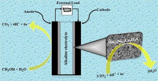
Mn-Ni-Co-O Spinel Oxides towards Oxygen Reduction Reaction in Alkaline Medium: Mn0.5Ni0.5Co2O4/C Synergism and Cooperation

by
Thabo Matthews
1,
Tarekegn Heliso Dolla
2,
Sandile Surprise Gwebu
1,
Tebogo Abigail Mashola
1,
Lihle Tshepiso Dlamini
1,
Emanuela Carleschi
3,
Patrick Ndungu
1 and
Nobanathi Wendy Maxakato
1,*
1
Department of Chemical Sciences, University of Johannesburg, Doornfontein 2028, South Africa
2
Department of Chemistry, Wolaita Sodo University, Wolaita Sodo P.O. Box 138, Ethiopia
3
Department of Physics, University of Johannesburg, Auckland Park 2006, South Africa
*
Author to whom correspondence should be addressed.
Submission received: 19 July 2021 / Revised: 26 August 2021 / Accepted: 27 August 2021 / Published: 31 August 2021

Abstract

:
Mn-doped spinel oxides MnxNi1−xCo2O4 (x = 0, 0.3, 0.5, 0.7, and 1) were synthesized using the citric acid-assisted sol–gel method. The Mn0.5Ni0.5Co2O4 (x = 0.5) supported on carbon nanosheets, Mn0.5Ni0.5Co2O4/C, was also prepared using the same method employing NaCl and glucose as a template and carbon source, respectively, followed by pyrolysis under an inert atmosphere. The electrocatalytic oxygen reduction reaction (ORR) activity was performed in alkaline media. Cyclic voltammetry (CV) was used to investigate the oxygen reduction performance of MnxNi1−xCo2O4 (x = 0, 0.3, 0.5, 0.7, and 1), and Mn0.5Ni0.5Co2O4 was found to be the best-performing electrocatalyst. Upon supporting the Mn0.5Ni0.5Co2O4 on a carbon sheet, the electrocatalytic activity was significantly enhanced owing to its large surface area and the improved charge transfer brought about by the carbon support. Rotating disk electrode studies show that the ORR electrocatalytic activity of Mn0.5Ni0.5Co2O4/C proceeds via a four-electron pathway. Mn0.5Ni0.5Co2O4/C was found to possess E1/2(V) = 0.856, a current density of 5.54 mA cm−2, and a current loss of approximately 0.11% after 405 voltammetric scan cycles. This study suggests that the interesting electrocatalytic performance of multimetallic transition metal oxides can be further enhanced by supporting them on conductive carbon materials, which improve charge transfer and provide a more active surface area.

Graphical Abstract

1. Introduction

Fuel cells are promising and efficient energy conversion systems that utilize sustainable energy sources, such as hydrogen or biofuels. Due to the inherent efficiencies and use of sustainable fuels, fuel cells can help to reduce greenhouse gas emissions and mitigate future energy supply issues (such as blackouts or load-shedding events) [1,2]. Direct alcohol fuel cells (DAFCs) produce electricity through oxidation of alcohol fuel and reduction of oxygen gas at the anode and cathode electrodes, respectively [3,4,5]. Owing to their ability to utilize variable fuel sources, ease of integration, compatibility with different systems, and milder operating conditions, DAFCs have several advantages over their competitors [5]. However, the commercialization of DAFCs is hindered by low power density and high setup costs arising from costly platinum-based electrocatalysts. Hence, current research targets electrode material improvement, operation condition optimization, and increasing the power output.
Oxygen is the best cathode candidate for all the cathodic electron acceptors due to its high reduction potential and abundance [6,7]. The performance of fuel cell devices depends on the kinetics of the oxygen reduction reaction at the cathode. The kinetics of the ORR are generally sluggish [8,9,10,11]; therefore, a need exists to develop novel cathodic electrocatalytic materials to drive electrode reactions that regulate the power density of energy devices [10,12].
Non-precious metal-based electrocatalysts for ORR have been extensively studied. Among them, spinel metal oxides show excellent performance in an alkaline medium towards ORR. Spinel oxides are compounds that have the general structure AB2O4, with A and B having tetrahedral (Td) and octahedral (Oh) occupancies, respectively [13,14,15,16]. Spinel oxides are possible substitutes for precious metal ORR electrocatalysts because they have variable valences, flexible structure, and remarkable redox stability. They are also abundant, cheap, and easy to prepare [17,18,19]. The literature has well documented an improvement in the electrochemical and physicochemical properties of transition metal oxides brought about by a stoichiometric combination of Ni and Co [17,20]. The electrocatalytic properties of spinel oxides are based on the spinel lattice’s electronic stability and geometric orientation. The cations within the spinel lattice can change valence states, leading to the formation of “electro-conductivity chains,” facilitating electron movement. Therefore, these electro-conductivity chains contribute to the electrocatalytic activity towards the ORR of spinel oxides [21].
In alkaline conditions, the cobaltite-based spinel oxides, MCo2O4 (where M = Mn, Ni, Cu, Fe), are very promising ORR electrocatalysts [22,23,24]. Merabet et al. [25] used the hydrothermal method to synthesize the crystalline MnCo2O4 spinel with a catalytic activity superior to Co3O4. Hu et al. [26] independently demonstrated that nanocrystalline Mn3O4@CoxMn3-xO4 prepared by a rapid room temperature procedure possesses remarkable catalytic activity towards ORR.
Ternary spinel oxides, specifically the Mn–Ni–Co systems, possess good physicochemical characteristics, modified by intrinsic morphological nano-structural control. The properties of ternary systems are determined by the different synthetic methods that have been adopted, such as the hydrothermal method [13,27], wet methods [28], and combustion [29]. The availability of a range of methods gives room for tailored stoichiometric metallic compositions of the spinel lattice [29,30]. A ternary spinel system has a pronounced metallic synergy effect, which improves the spinel-based electrocatalysts’ catalytic and stability properties [13,31,32,33].
Of the facile synthetic methods available for preparing a ternary spinel, the citric acid-based sol–gel route has the advantage of stoichiometric control through metallic mixing at the atomic level. Moreover, if two metals have similar atomic radii, a ternary spinel cobaltite system of the type CxA1−xB2O4 is possible. For example, Dolla et al. [34] synthesized MnxZn1−xCo2O4 by a facile co-precipitation method resulting in Mn-Zn-Co oxide microspheres. In the same vein, Nestola et al. [35] have prepared (AxB1−x)Fe2O4 using the same process. They studied the electrocatalytic activity of MnxCu1−xCo2O4 in an alkaline medium, and it was concluded that copper substitution could enhance the ORR electrocatalytic properties [36].
Herein, we report an investigation of the effect of doping of Mn into the NiCo2O4 parent spinel towards the electrochemical properties for ORR. A series of MnxNi1−xCo2O4 spinel oxide-based electrocatalysts were as synthesized using a modified citrate-assisted sol–gel method to improve ORR activity. The electrocatalytic activity of MnxNi1−xCo2O4 oxide towards ORR was optimized, and the Mn0.5Ni0.5Co2O4 spinel oxide electrocatalyst proved to be the best ORR electrocatalyst after evaluation using cyclic voltammetry, chronoamperometry, and cyclic stability tests. The best-performing electrocatalyst, Mn0.5Ni0.5Co2O4, was then supported on a carbon sheet (Mn0.5Ni0.5Co2O4/C) to show the performance enhancement of carbon support. After this, physicochemical and electrochemical comparisons between MnxNi1−xCo2O4 and Mn0.5Ni0.5Co2O4/C studies were made.

2. Results and Discussions

2.1. Spinel Synthesis Chemistry

A series of MnxNi1−xCo2O4 spinel electrocatalysts were synthesized using the citric acid-assisted sol–gel method. As shown in Equation (1), acetates of Mn, Ni, and Co were mixed in water to form a metal acetate homogeneous complex.
p M + yH + z ( cit ) M p H q ( Cit ) r
where M p H y ( Cit ) z = xMn 2 + / HCit 3 , ( 1 x ) Ni 2 + / HCit 3 , Co 2 + / HCit 3 .
Citric acid was used as a chelating agent. After the homogeneous metal acetate solution was formed, ammonia was added to increase the pH to 7 (these metal ions reached complete complexation at this optimal pH) according to Equation (2):
M p H y ( Cit ) z + NH 3 NH 3 H y + + M p ( Cit ) z
where M p ( Cit ) z = xMn 2 + ( Cit ) z + ( 1 x ) Ni 2 + ( Cit ) z + Co 2 + ( Cit ) z .
To the metal acetate solution, citric acid was added to form citrate anions coordinated to metallic cations. To M p ( Cit ) z ethylene glycol was added to assist with the gelation process. The reaction is illustrated in the following equation.
xMn 2 + ( Cit ) z + ( 1 x ) Ni 2 + ( Cit ) z + Co 2 + ( Cit ) z a , b , c [ xMn 2 + · ( 1 x ) Ni 2 + · Co 2 + ] gel
a = ethylene glycol, b = 80–90 °C, c = 6 h
The resulting [ xMn 2 + · ( 1 x ) Ni 2 + · Co 2 + ] -polymeric gel was dried overnight at 100 °C to evaporate the water formed during the citrate–ethylene glycol polymerization reaction. After that, the dried gel was calcined at 450 °C, and the metal oxide spinel system was developed. During calcination, carbon dioxide gas was produced, thus leading to a material with increased porosity. The following equation shows this two-stage process:
( xMn 2 + · ( 1 x ) Ni 2 + · Co 2 + )   gel a , b Mn x Ni 1 x Co c , d , e Mn x Ni 1 x Co 2 O 4 Black   powder
a = dry overnight, b = 100 °C, c = 450 °C, d = 5 h, e = calcination
As shown in reaction Scheme S2, Mn0.5Ni0.5Co2O4/C was synthesized by mixing stoichiometric amounts of metallic precursors to form [ 0.5 Mn 2 + · ( 0.5 ) Ni 2 + · Co 2 + ] C 6 H 12 O 6 cubic   NaCl . Sodium chloride was utilized as a template because it is less soluble than metal precursors and glucose. [ 0.5 Mn 2 + · ( 0.5 ) Ni 2 + · Co 2 + ] C 6 H 12 O 6 cubic   NaCl was oven treated to form [ 0.5 Mn 2 + · ( 1 x ) Ni 2 + · Co 2 + ] / C coated   cubic   NaCl . The resultant composite was then pyrolyzed at 750 °C in the presence of PVP, and the release of CO2 led to the formation of a material with a porous structure (see SEM in the SI section). The [ 0.5 Mn 2 + · ( 0.5 ) Ni 2 + · Co 2 + ] / C coated   cubic   NaCl was then calcined in air at 450 °C to form porous crystalline Mn0.5Ni0.5Co2O4/C−coater cublc NaCl. The NaCl template was washed off with H2O/CH3CH2OH (0.5:1, v/v).

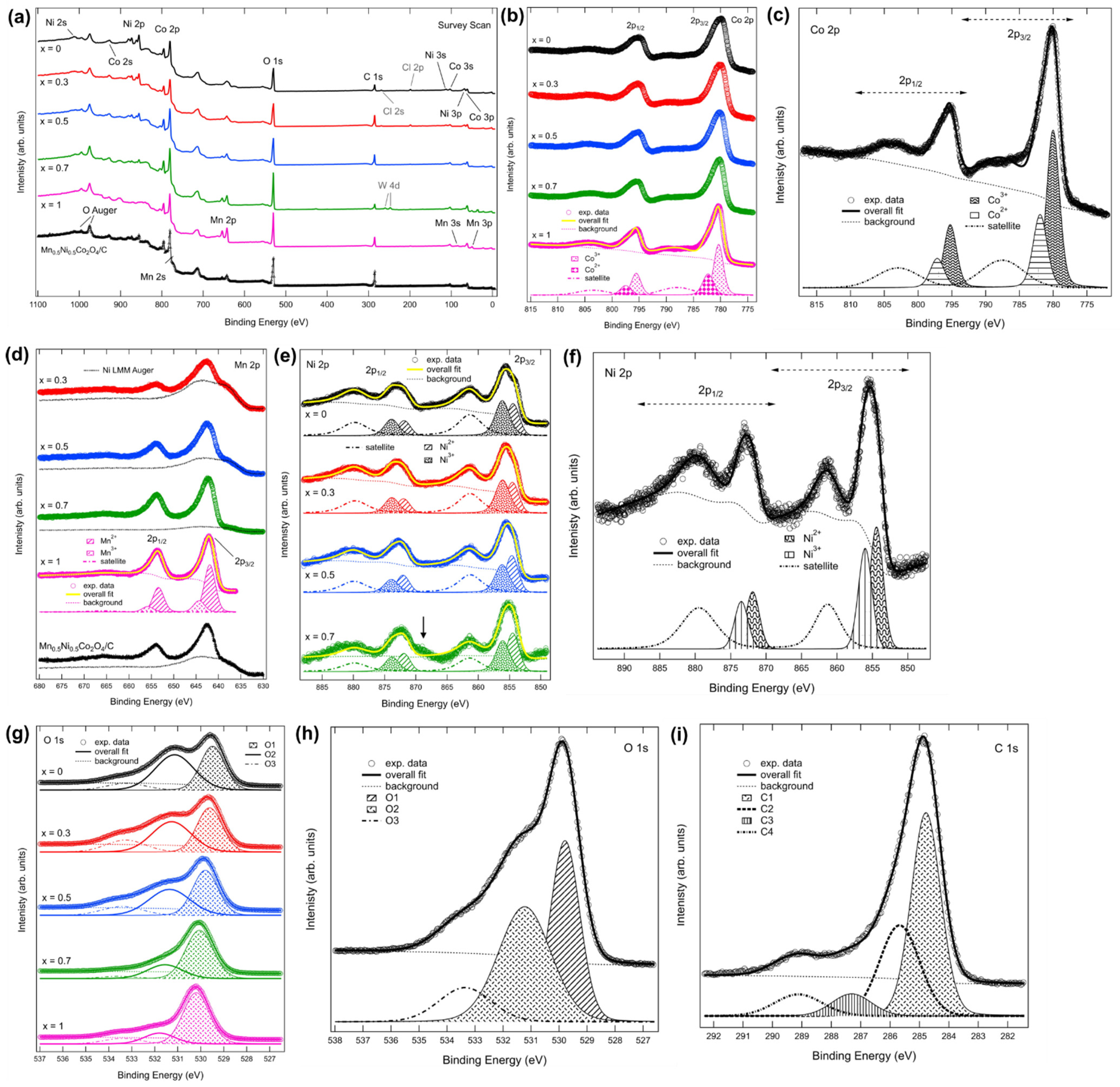
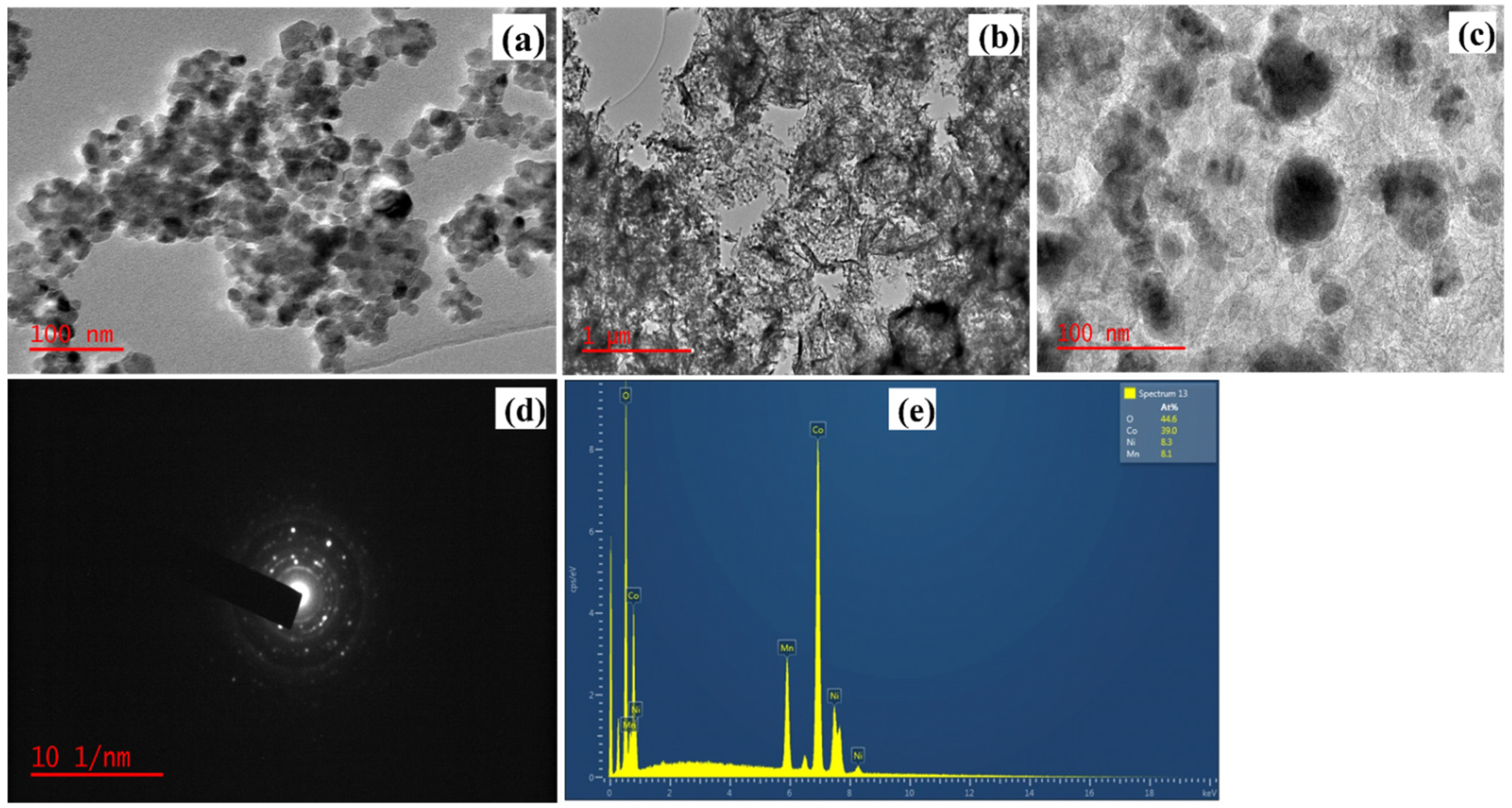
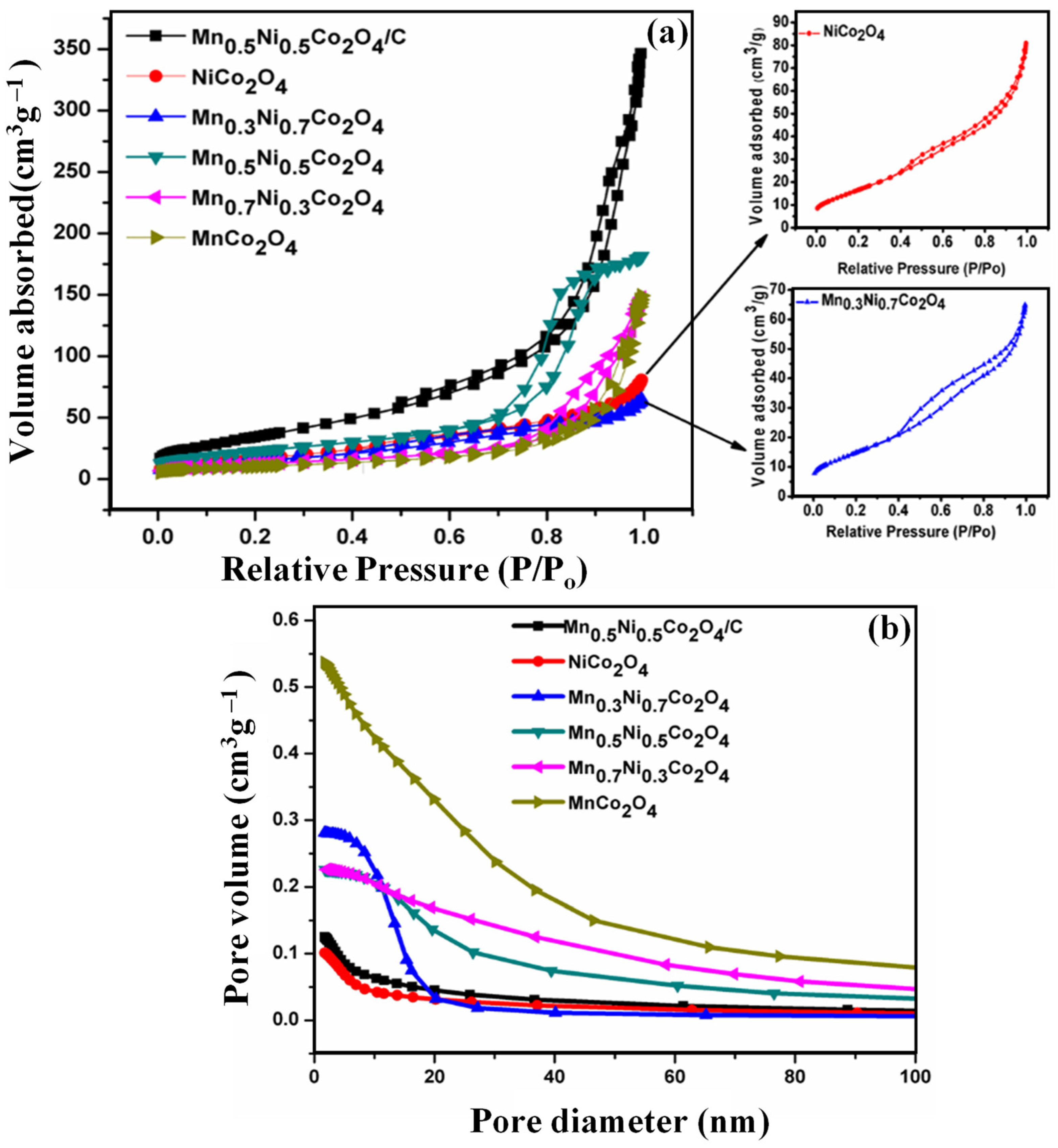
2.2. Physicochemical Characterization

The phase purity and crystal structures of the MnxNi1−xCo2O4 were investigated using powder X-Ray Diffraction (XRD) and are shown in Figure 1a. The XRD pattern confirmed that all the spinel oxides exhibited a cubic spinel structure (Fd 3 m) and no impurity was observed. The diffraction peaks are observed at 2θ values of 18.88°, 31.18°, 36.7°, 44.64°, 55.67°, 59.05°, and 64.89°, which were, respectively, indexed to the (111), (220), (311), (400), (422), (511), and (440) crystal planes of a cubic NiCo2O4 spinel (JCPDS No. 73-1702) [37,38]. All the diffraction patterns of the Mn-doped samples were found to be similar to the NiCo2O4, thus providing evidence for the formation of a homogeneous solid solution and the adoption of the spinel cubic structure. The average crystal sizes were calculated using the Scherrer equation on peak widths at 2θ = ~36° (331) and are presented in Table 1. The lattice parameters were calculated and observed to be consistent with the previous report [13]. The lattice parameters increase with manganese concentrations from x = 0 to 0.5 and decrease onwards to x = 1. Based on the inverse spinel-type NiCo2O4 crystal structure, Co x 2 + Co 1 - x 3 + [ Co 3 + Ni 1 - x 2 + Ni x 3 + ] O 4   [39], it can be explained that manganese substitution for nickel takes place in the octahedral position up to x = 0.5, thus increasing the lattice parameter [40]. Beyond x = 0.5, either the manganese or nickel or both cations can move from Oh (A) to Td (B) sites, leading to the Mn2+/Mn3+ or Ni2+/Ni3+ Oh (A) and Td (B) partial residence. In Figure 1b, the peak at 2θ = 26.1° (marked with * asterisks) is attributed to carbon coexisting in the obtained product showing the carbonization process’s effectiveness. Thus, Mn0.5Ni0.5Co2O4/C has a graphitic carbon structure and is well developed inside the composite.
To further understand the structures of MnxNi1−xCo2−xO4 and the carbon support formed on Mn0.5Ni0.5Co2O4/C), Raman spectroscopy analysis was carried out, and the results are shown in Figure 2a,b, respectively. The characteristic peaks for the M–O bond stretching vibration were observed at 435 cm−1 to 735 cm−1 for the MnxNi1−xCo2−xO4 series corresponding to the Mn–O, Ni–O, and Co–O bonds [13,41,42]. A slight shift of peaks was observed across the synthesized spinel oxide series, and these were attributed to the defects and strains arising from the doping of Mn in NiCo2O4. In the Raman spectrum of Mn0.5Ni0.5Co2O4/C, two characteristic peaks appearing at 1333 cm−1 and 1564 cm−1 were observed, and these were indexed to the D and G bands of the graphitic carbon, respectively. The integrated peak intensity ratio of the D and G bands (ID/IG) provides a base assessment for the degree of graphitization of carbon material. The ID/IG ratio can be used to quantify the defects within carbonaceous materials. The D band is due to the disorderliness or the defects within the graphitized lattice plane, whereas the G band is attributed to the extent of the sp2-hybridization of the graphitized structure [43]. For the Mn0.5Ni0.5Co2O4/C hybrid, the calculated ID/IG is 1.17. A large value of ID/IG shows a high degree of graphitic defects, which is advantageous in electrocatalysis because the defects contribute towards the anchoring of Mn0.5Ni0.5Co2O4 in the carbon matrix, thus allowing easy electrolyte movement and exposure of active catalytic sites that facilitate electrocatalytic activity.
The FTIR of the series of MnxNi1−xCo2O4 spinel oxides (Figure 3) was used to identify the bending and stretching vibrations and give more insight into the spinel formation. Two intense peaks were observed below 1000 cm–1. Specifically, the peaks appearing in the range 500–688 cm–1 (oval dotted line in Figure 3) were ascribed to the stretching vibrations of tetrahedral (Td) and octahedral (Oh) occupancy of M–O (M = Mn, Ni or Co). M–O intensities were much pronounced for Mn0.3Ni0.7Co2O4, Mn0.5Ni0.5Co2O4, Mn0.7Ni0.3Co2O4, and Mn0.5Ni0.5Co2O4/C as compared to NiCo2O4 and MnCo2O4. The high intensities are probably due to the three compounded M–O moieties, namely Mn–O, Ni–O, and Co–O. A shift in the peak position of the doped samples (Mn0.3Ni0.7Co2O4, Mn0.5Ni0.5Co2O4, Mn0.7Ni0.3Co2O4, and Mn0.5Ni0.5Co2O4/C) relative to the undoped samples (NiCo2O4 and MnCo2O4) was observed. This shift can be attributed to the Td and Oh occupancy stretches arising from the Mn doping of the spinel matrix. We believe that the presence of a split OH peak appearing between 3160 and 3421 cm–1 might be due to the different OH adsorbed on spinel and carbon sheets. This, in turn, confirms the presence of a carbon sheet in the synthesized sample due to OH peak overlap. The FTIR also showed absorption peaks between 2297 and 2441 cm–1, due to the CO2 sorption molecule at the surface. The stretching vibrations of the CH2 group (shown by a big purple arrow) occurred between 2822 and 2972 cm–1 [14]. Carboxyl (–C=O) symmetric and asymmetric stretching bands were observed at 1547–1711 cm–1. These bands emanate from the trace organic precursors of the support material [44], which were also confirmed by the presence of C 1s core level of the XPS spectrum shown in Figure 4i.
X-ray photoelectron spectroscopy (XPS) of the MnxNi1−xCo2O4 series and Mn0.5Ni0.5Co2O4/C was used to investigate the oxidation state and to understand the electronic structure and composition of the elements on the surface. Survey scans for the MnxNi1−xCo2O4 and Mn0.5Ni0.5Co2O4/C samples (Figure 4a) show the presence of Mn, Ni, and Co (the LMM Auger lines of Mn, Ni, and Co), O (the O KVV Auger lines), and C (C 1s) at 285 eV binding energy (BE), which is due to the presence of absorbates on the surface of the MnxNi1−xCo2O4 (ex situ samples).
The Co 2p spectra for MnxNi1−xCo2O4 and Mn0.5Ni0.5Co2O4/C are displayed in Figure 4b,c. This BE region is divided into two main regions, that is, ~777–792 eV for Co 2p3/2 and ~792–807 eV for Co 2p1/2 [45,46], and this is consistent with the line shape of the mixed-valent Co3O4 where Co ions have both Co3+ and Co2+ oxidation states [47,48]. For example, the fit to the x = 1 sample is shown at the bottom of Figure 4b for the entire series. The spectrum for Mn0.5Ni0.5Co2O4/C is fitted separately (Figure 4c). The best fit to the data for the x = 1 sample in Figure 4b shows two spin–orbit doublets (separated by a spin–orbit energy splitting of 15.2 eV) for the main peaks and one doublet with a broad line shape for the satellite. These two components can be ascribed to the Co3+ (BE 2p3/2 = 780.35 eV), which accounts for roughly two-thirds of the spectral weight (taking into account the potential error associated with the choice of background for the fit) and Co2+ oxidation states (BE 2p3/2 = 782.27 eV), which accounts for the other one-third of the spectral weight. Similarly, for Mn0.5Ni0.5Co2O4/C, the BE for Co3+ 2p3/2 (66% of the spectral weight) is 780.02 eV, while that of Co2+ 2p3/2 (34%) is 781.94 eV, which is consistent with the relevant literature on Co3O4-type compounds [47,48]. The Co 2p core-level line shape shows that Co is very robust towards the Mn-to-Ni substitution.
Figure 4d shows the Mn 2p BE region for the x = 0.3, 0.5, 0.7, 1 series, and Mn0.5Ni0.5Co2O4/C. This energy region comprises two main BE regions, namely ~638 eV to ~649 eV (2p3/2) and ~649 eV to ~660 eV (2p1/2). The Mn 2p BE region overlaps with the Ni LMM Auger emission, whose line shape was measured for the Mn-free sample of the series and was appended as a solid black line underneath the Mn 2p spectra plotted in Figure 4d. Before fitting the data, the line shape of the Ni Auger peak (normalized to the stoichiometric amount of Ni in each sample) was subtracted from the row data in order to obtain the Mn 2p contribution to the XPS signal in this BE region. Mn is present mainly in the Mn2+ oxidation state [13,34]. The BEs of the 2p3/2 peaks of the fitted components are 641.95 eV (Mn2+—80% of the spectral weight) and 644.39 eV (Mn3+). The line shape of Mn 2p for Mn0.5Ni0.5Co2O4/C overlaps very well with that of the non-supported equivalent sample x = 0.5 of the spinel oxide series, indicating that the presence of carbon support does not affect the line shape of this core level.
Figure 4e,f displays the Ni 2p BE region for samples (d) x = 0, 0.3, 0.5, 0.7 and Mn0.5Ni0.5Co2O4/C. This energy region comprises two main BE regions, namely from ~850 eV to ~870 eV (Ni 2p3/2) and ~870 eV to ~890 eV (2p1/2) (Table S1). A spin–orbit energy splitting of 17.37 eV was used. The component at lower BE was assigned to the Ni2+ oxidation state, and the one at higher BE to the 3+ oxidation state [13,49,50]. Interestingly, there is a change in the Ni2+/Ni3+ ratio across the series. Samples x = 0 and x = 0.3 have the Ni3+ oxidation state in the majority. With regard to the Ni 2p spectrum for the x = 0.7 sample, the vertical arrow in the figure indicates the Co Auger broad peak, which overlaps the Ni 2p core level in this BE region; the Co Auger line becomes more relevant in this sample as it is the one with the least amount of Ni in the series. This Auger line’s presence severely affects the goodness of fit for this sample, as the fit parameters were kept consistent with those for the other samples. However, the oxidation states are inferred from the relative intensity of the main peaks, so the inconsistency of the fitting for the x = 0.7 sample in the satellite region should not affect the final result. By contrast, the other two samples have an almost even distribution of the Ni2+ and Ni3+ oxidation states. This is due to the electrocatalytic activity of ratio x = 0.5 and the disappearance of the pseudo-bifunctionality in x = 0.7 (Figure S6) and x = 0 (Figure S7). Furthermore, Mn0.5Ni0.5Co2O4/C shows the least amount of Ni3+ compared to the MnxNi1−xCo2O4 series. This means that, during the electrocatalytic process, the redox couple Ni2+/Ni3+ can provide electrons easily for the electro-reduction process.
Figure 4g,h shows the O 1s spectra for the MnxNi1−xCo2O4 series and Mn0.5Ni0.5Co2O4/C, respectively. The three components are labeled O1, O2, and O3. O1 is ascribed to the stoichiometric oxygen in the main matrix of the perovskites [13,51] and O2 corresponds to oxygen vacancies or defects [13]. As shown in Table 2, Mn0.5Ni0.5Co2O4/C has the highest percentage of component O2 (high oxygen vacancy/defects corresponding to high catalytic activity). Lastly, O3 is attributed to surface contaminants, that is, chemisorbed oxygen [41]. Interestingly, while the energy difference between each component remains consistent from sample to sample, the overall BE shifts to higher values from x = 0 to x = 1, suggesting that the addition of Mn makes the system slightly more insulating. This highlights the need for supporting Mn0.5Ni0.5Co2O4 on a carbon sheet to enhance conductivity.
Lastly, Figure 4i shows the fitted C 1s spectrum for Mn0.5Ni0.5Co2O4/C and relative percentages in Table S2. While C1 was attributed to C–C/C=C chemical bonds, C2 was attributed to C–OH bonds; by the same token, C3 to C=O and C4 to O–C=O are various oxygen moieties [52]. These correspond with the results of the FTIR spectra shown in Figure 3. C1 has the highest percentage of C–C/C=C chemical bonds, thus confirming the graphitic and carbonaceous nature of the support material and the carbon source’s graphitization (glucose). This, therefore, confirms the presence of carbon sheets.
The morphology of the prepared MnxNi1−xCo2O4 and the Mn0.5Ni0.5Co2O4 supported on carbon was investigated using transmission electron microscopy (TEM). Figure 5a shows TEM images of the Mn0.5Ni0.5Co2O4, which are agglomerated. Figure 5b,c shows the TEM images of Mn0.5Ni0.5Co2O4/C at different magnifications. Figure 5b shows the overview of Mn0.5Ni0.5Co2O4 (black dots) on the carbon sheet. Figure 5c shows the magnified image of Mn0.5Ni0.5Co2O4/C, showing the dispersion of the Mn0.5Ni0.5Co2O4 nanoparticles in the carbon matrix. Thus, Figure 5b,c shows that employing carbon support helps in reducing the agglomeration, concluding that Mn0.5Ni0.5Co2O4 nanoparticles are spread well over the carbon nanosheet. The SAED (selected area electron diffraction) pattern in Figure 5d shows that Mn0.5Ni0.5Co2O4/C is polycrystalline. Figure 5e shows the EDS spectrum of the Mn0.5Ni0.5Co2O4 sample, confirming the presence of Mn, Ni, Co, and O in the sample. In Figure S3, the compositions with x = 0.3, 0.5, and 0.7 show cubic type morphology (red squares), while the shapes of x = 0 and 1 are not clearly defined due to agglomeration. The doping of Mn had affected the “shape” morphology as shown when x = 0 to 1 (Figure S3). On the one hand, Figure S4a,b shows the respective SEM and TEM images of Mn0.5Ni0.5Co2O4. The TEM images show aggregates of small nanoparticles (as dark spots), which could be due to the interaction between the nanoparticles resulting from the high surface energy of the nanoparticles.
Table 1 lists the textual properties of MnxNi1−xCo2O4, and Mn0.5Ni0.5Co2O4/C. Figure 6 shows the nitrogen adsorption–desorption isotherms and pore size distribution of a series of MnxNi1−xCo2O4. As per IUPAC guidelines, the nitrogen adsorption–desorption isotherms for the MnxNi1−xCo2O4 series are type IV. The exception is observed with the Mn0.5Ni0.5Co2O4 sample, classified as a type V isotherm (elongated S-type). The change in the sizes of the nanoparticles probably accounts for changes in the agglomeration and hence changes in the voids between the nanoparticles, which could account for the change in the isotherm shapes. The elongated S-type means that as more O2 molecules move towards the Mn0.5Ni0.5Co2O4-modified GCE during hydrodynamic analysis, it becomes easier for more O2 to be fixed. This phenomenon occurs in a cooperative adsorption manner via side-by-side adsorption association between O2-adsorbed molecules, proving the cooperative nature of the electrocatalysts [53]. This elongated S-type shape supports the activity of Mn0.5Ni0.5Co2O4 since the O2 molecule is (a) monofunctional, (b) exhibits moderate intermolecular attraction, and (c) meets strong competition due to the hydrodynamic ORR process. All the requirements listed in a, b, and c should be met for the elongated S-shape to be realized. At P/Po = 0.7–0.8, the hysteresis loops show distinctive H3 hysteresis loops for the MnxNi1−xCo2O4 series, indicating that the agglomerated nanoparticles’ mesoporous nature makes up the various spinel samples. However, the Mn0.5Ni0.5Co2O4/C sample exhibits a H1 hysteresis loop, meaning that Mn0.5Ni0.5Co2O4/C may have a more uniform porous structure. The Mn0.5Ni0.5Co2O4/C showed a different hysteresis loop relative to Mn0.5Ni0.5Co2O4 because of the pore overlap between the Mn0.5Ni0.5Co2O4 and the carbon sheet. This overlap might have resulted in a narrow range of uniform mesopores [54,55,56].

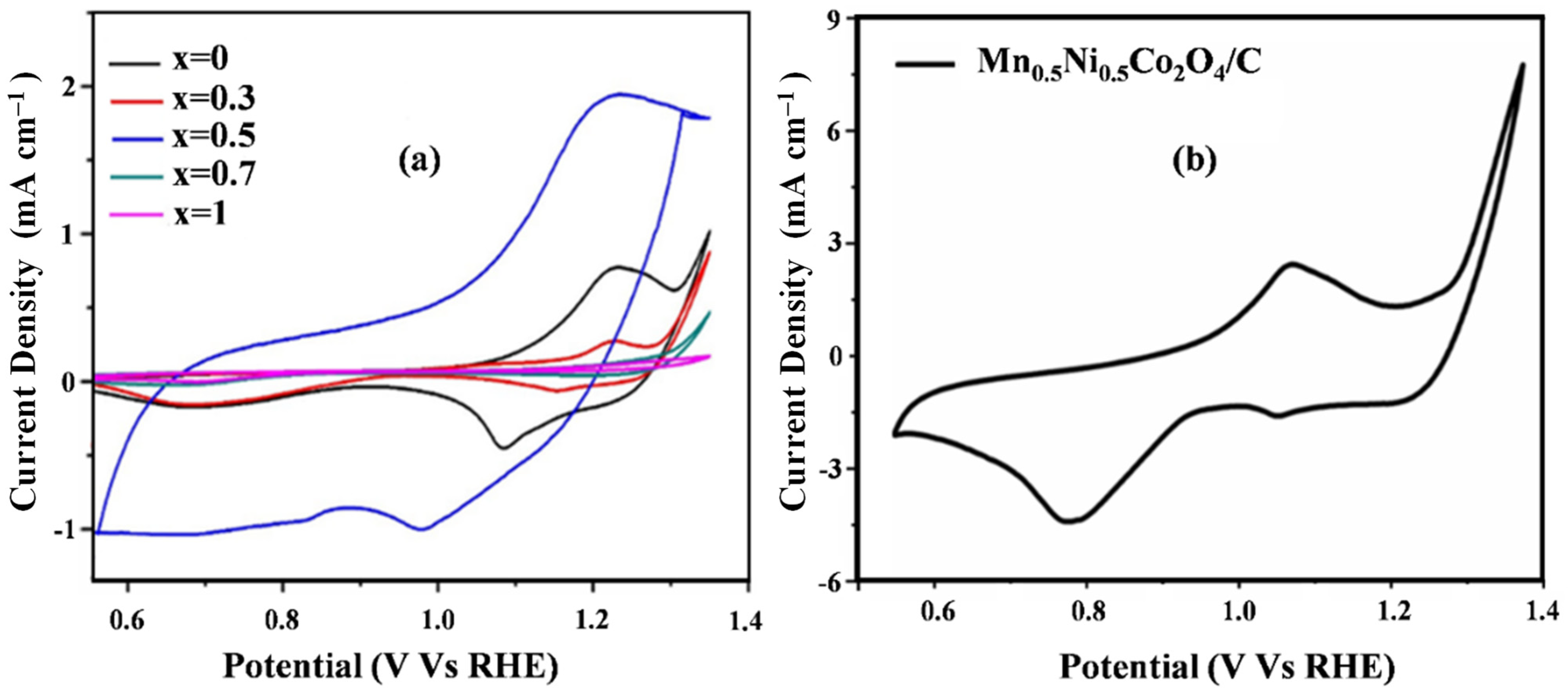
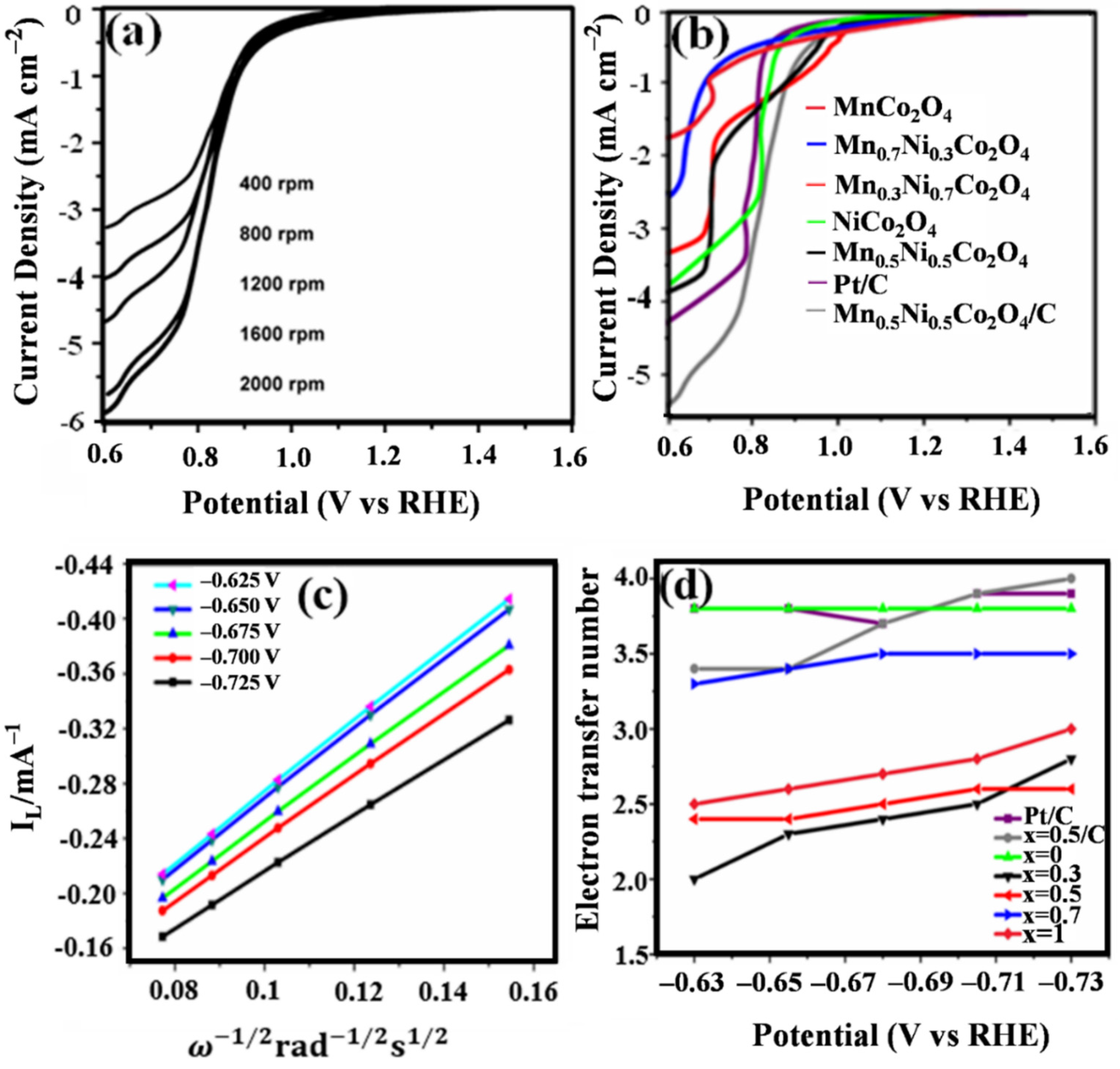
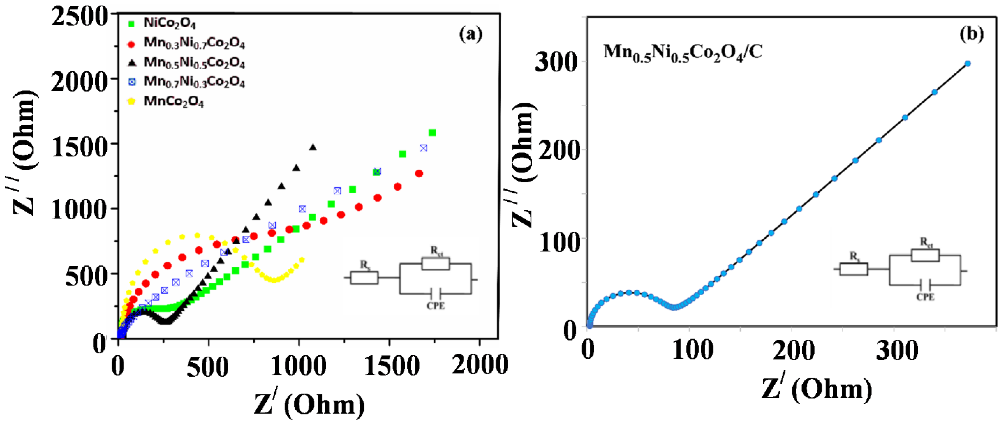
2.3. Electrochemical Evaluation of ORR Activity

The electrocatalytic activities of MnxNi1−xCo2O4, 0 ≤ x ≤ 1 nanocomposites were elucidated using cyclic voltammetry within the 0.55 to 1.35 (V vs. RHE) range (Figures S3–S8). This necessitated checking the electrocatalytic behavior of the synthesized electrocatalysts in an alkaline medium and selecting the best electrocatalyst within the MnxNi1−xCo2O4, 0 ≤ x ≤ 1 series. The best-performing electrocatalyst was then supported on a carbon sheet to improve the electrocatalytic activity, durability, and stability. The stability and durability were evaluated using chronoamperometry and cyclic voltammetry studies.
The dependence of the electrochemical behavior of MnxNi1−xCo2O4 on the scan rate (10–100 mV/s) was studied (Figures S3–S8). It was possible to conduct the scan rate studies in the whole range because the faradaic current was more dominant than the capacitive current. A linear correlation of scan rate to cathodic peak current was observed (Figures S3–S8b), indicating that the electroactive O2 is firmly entrapped on the modified GCE cathode surface. This means that the species are confined in the bulk of the electrode surface, except for Mn0.7Ni0.3Co2O4, which does not have a well-defined pattern. This anomaly can be explained using the XPS result (Table S1), which shows that Mn0.7Ni0.3Co2O4 has approximately the same Ni2+/Ni3+, leading to a reduction in the redox couple behavior, as evidenced in Figure S6. A negative shift in potential was observed when the scan rate was increased, indicating greater propensity for oxygen reduction. Figures S3–S8b show a plot of Epc vs. log v, which gave linear regressions with R2 greater than 0.9600. This indicates a strong correlation between the cathodic peak potential and the logarithmic value of potential. An anomaly was observed for Mn0.7Ni0.3Co2O4, which has an R2 of 0.7416 (Figure S6b). From the plots of Epc vs. log v, a Tafel slope (b) was calculated using Equation (5) [57]:
E p c = b 2 l o g   v + c o n s t a n t
where b 2 is the plot slope and b is the Tafel slope.
Evaluating E p c ( l o g   v ) gives V dec−1 and no distinct change in the slope of the plots was observed, indicating the exact mechanism in the O2 electro-reduction. The E p c ( l o g   v ) for Mn0.5Ni0.5Co2O4 was found to be 0.400 V dec−1 (the highest Tafel slope of all ratios) and b 2 = 0.2002 , thus giving b = 2 × 0.2002 = 0.400   V   dec −1. The other Tafel values are shown in Table S3. The higher Tafel value obtained for Mn0.5Ni0.5Co2O4 indicates the porous nature of the synthesized materials. The small Tafel (0.0623 V dec−1) for Mn0.3Ni0.7Co2O4 means a probable 2-electron oxygen electro-reduction pathway, confirmed by the Koutecky–Levich plots. The Tafel value relates to a fast over-potential increase with the current intensity, which indicates the good catalytic activity of the electrocatalysts and is therefore commendable for electrocatalytic reduction of O2.
In Figures S3–S8c, the plot of Icp vs. s c a n   r a t e   emanating from the voltammetry studies gave a linear correlation between the two, indicating a diffusion-controlled process. Thus, no external force is required to push the reacting species to the surface of the electrodes. The surfaces and intrinsic properties of the electrocatalysts are essential in the electrochemical performance of the MnxNi1−xCo2O4 spinel oxide series. To evaluate these characteristics, cyclic voltammetry within the 0.55 to 1.35 (V vs. RHE) range at 50 mV s−1 was used, and the resulting voltammograms are shown in Figure 7. As shown in Figure 7, the electrocatalysts have well-established peaks within the potential window, relative to Figure S9 where the cv cycles show no reduction peaks in N2-saturated 0.1 M KOH. The cyclic voltammograms for NiCo2O4, Mn0.3Ni0.7Co2O4, and Mn0.5Ni0.5Co2O4 (Figure 7a) show that their reduction curves have shifted to the more positive values, relative to Mn0.7Ni0.3Co2O4, MnCo2O4, and Mn0.5Ni0.5Co2O4/C), which have reduction curves shifted to the negative values. Mn0.5Ni0.5Co2O4 of MnxNi1−xCo2O4 has a more positive onset potential than all ratios (1.10 (V vs. RHE)), indicating its low over-potential ORR. Reaction kinetics of Mn0.5Ni0.5Co2O4 occurred at 0.78 (V vs. RHE) half-wave potential, with a 1.10 (V vs. RHE) onset potential Tafel of 0.400 V dec−1. This qualifies Mn0.5Ni0.5Co2O4 as the most electroactive electrocatalyst of the series for the reduction of oxygen because it follows Equations S(2)–S(18).
Following the onset potential and current density, the order of ORR activities of the electrocatalysts is as follows; Mn0.5Ni0.5Co2O4/C > Mn0.5Ni0.5Co2O4 > NiCo2O4 > Mn0.3Ni0.7Co2O4 > Mn0.7Ni0.3Co2O4 > MnCo2O4. From these ORR activities, it can be seen that Mn0.5Ni0.5Co2O4/C (Figure 7b) has the highest current density due to the increased electroactive surface area (Table 1) resulting from high oxygen vacancy sites revealed by XPS [13], low charge transfer resistance (Table 3), and low agglomeration (Figure 5a). This highly pronounced ORR activity can be accounted for by the synergy of the carbon support and existence of multimetallic centers metallic within the spinel lattice. The carbon sheet as a support material for Mn0.5Ni0.5Co2O4 enhanced the electron movement during the electro-reduction process. For the reduction peaks shown by the MnxNi1−xCo2O4 spinel series at E 1 2 , the oxygen reduction pathway and mechanisms vary with catalytic composition. Thus, O2 adsorption is relative to catalytic surface geometry, the binding energy, and the available active sites of the electrocatalysts. For the creation of hydroxyl species on the metallic oxide surface, the surface of the oxygen ligand must be protonated, which is counteracted by charge-compensation via metal cation (M) reduction (Mn3+, Mn4+, Ni3+, and so on) [13,58]. The formed metal hydroxide species (M–OH) will interact with O2 end-on or side-on arrangements [59]. Thus, the ORR mechanism proposed paths on the metal oxide surfaces would follow Equations S(2)–S(18) (Supplementary Materials) [60].
From the proposed mechanism, the MnxNi1−xCo2O4 spinel series utilizes electron hopping within the spinel lattice. There are also well-defined anodic peaks shown by NiCo2O4, Mn0.3Ni0.7Co2O4, and Mn0.5Ni0.5Co2O4, which can be ascribed to the oxidation of M2+ to M3+/M4+ (M = Co). Thus, in the alkaline medium, the mechanism is as follows [61]:
Step 1: OH adsorption
A * + O H e + A * O H
Step 2: O–H bond breaking
A * O H + O H e + H 2 O + A * O  
Step 3: formation of oxylato-oxygen/hydroperoxyl
A * O + O H e + A * O O H
Step 4: H2O and adsorbed O2 formation
A * O O H + O H H 2 O + e + A * O O  
Step 5: O2 desorption
A * O O O 2 + A *  
where A* is the active site.
For Mn0.5Ni0.5Co2O4/C, the redox peaks at 1.06 and 1.08 (V vs. RHE) are ascribed to reversible oxidation CoOOH + OH  CoO2 + H2O + e, that is the redox Co2+/Co3+ peak depicted in Equation S(1), which follows from Equation S(10) under Step 4 (Figure S8).
The ORR is a multi-electron process, depending on the catalyst used in the electro-reduction process. In alkaline electrolytes, ORR follows the direct four-electron pathway that involves direct oxygen reduction to hydroxyl ions (Equation (11); most desired pathway) and the indirect two-electron pathway, which produces H O 2 intermediate (Equations (12)–(14); less efficient pathway). The H O 2 is undesirable because it causes catalyst poisoning and corrosion of the fuel cell components, reducing electricity production. Thus, electrocatalysts must be engineered to facilitate the direct four-electron pathway, enhancing maximum electricity generation in fuel cells.
O 2 + 2 H 2 O + 4 e   4 O H
O 2 + 2 H 2 O + 2 e   H O 2 + O H
H O 2 + H 2 O + 2 e 3 O H
2 H O 2 4 O H + O 2
To better understand the ORR performance and mechanism of the electrocatalysts, we performed linear sweep voltammetry (LSV) measurements on the RDE in 0.1 M KOH saturated with O2. The RDE we used was modified with NiCo2O4, Mn0.3Ni0.7Co2O4, Mn0.5Ni0.5Co2O4, Mn0.7Ni0.3Co2O4, MnCo2O4, and the best-performing carbon sheet supported Mn0.5Ni0.5Co2O4/C. When potential is 0.6 (V vs. RHE), the resultant current density absolute values were in the sequence of Mn0.5Ni0.5Co2O4/C > Pt/C > Mn0.5Ni0.5Co2O4 > NiCo2O4 > Mn0.3Ni0.7Co2O4 > Mn0.7Ni0.3Co2O4 > MnCo2O4. It should be noted that the amplification of electrocatalytic activity as instigated by carbon support follows the same order of CV performance. Based on the effect of carbon support on electrocatalytic activity, the best-performing Mn0.5Ni0.5Co2O4 was supported on a carbon sheet to enhance its performance further.
Figure 8a shows LSVs at different rotation speeds 400–2000 rpm of the electrocatalyst used to investigate the electron transfer pathway for ORR. The LSV curves by RDE, Mn0.3Ni0.7Co2O4, MnCo2O4, and Mn0.5Ni0.5Co2O4 showed a characteristic two plateaued LSV curve signifying a peroxide pathway (Figure 8b). This provides evidence for an oxygen reduction mechanism via two successive two-electron processes (Equations (12)–(14)) [62]. From the LSV results, the Koutecky–Levich (K–L) plots (Figure 8c) were drawn following the K–L shown in Equation (15). The linear K–L line fitting plots suggest first-order reaction kinetics of O2 reduction. The average number of transferred electrons was calculated at different potentials (Figure 8d). The Mn0.5Ni0.5Co2O4/C, NiCo2O4, and Mn0.7Ni0.3Co2O4 spinel oxides had an average electron transfer exceeding 3.5. The most active electrocatalyst, Mn0.5Ni0.5Co2O4/C, had an average electron transfer of 3.7, comparable to the n value of Pt/C commercial catalyst n value. This pronounced electron transfer might be due to the synergistic interaction between the Mn0.5Ni0.5Co2O4 and the carbon sheet forming Mn0.5Ni0.5Co2O4/C that possesses the enhanced electron transfer facilitated by metallic cooperation within the spinel lattice. The hybridization of the carbon orbitals (of the support material) and Mn0.5Ni0.5Co2O4 occurs between split 3d orbitals of Mn, Ni, and Co and the 2p carbon orbitals. This interaction will cause electron density to be filled in the Fermi level, hence the exhibited electro-reduction catalytic activity of Mn0.5Ni0.5Co2O4/C. Thus, the electrons will flow from the carbon sheet to Mn0.5Ni0.5Co2O4, which causes the supported Mn0.5Ni0.5Co2O4 to be negatively charged, leaving the carbon sheet positively charged, hence the electrostatic inductive effect. The electrostatic inductive effect enhances electrocatalytic properties, for example, the electron conductivity resulting from the interaction between the carbon sheet pi-orbitals and Co split 3d orbitals, which comes in as a source of electrons for redox couples during oxygen electro-reduction.
Li et al. [63] have also reported the same interaction in spinel MnCo2O4/nanocarbon hybrids. The carbon introduction amplified the electronic state of the M3+/M2+ redox couple participation in ORR. The carbon sheet established covalent interfacial M–O–C interactions. The C–O electron sharing reduces the electron density around M. This shifts the redox couple to the M2+, which improves the ORR electrocatalytic activity [14]. With that in mind, it is worth mentioning that the nearly two-electron electrocatalysts can also be enhanced by utilizing carbon support to enhance electron and charge movement. In turn, the improved electron and charge movement might improve the n number during ORR, pointing them to a nearly four-electron pathway. Thus, it should be noted that employing a support material enhances the electrocatalytic activity that follows the same activity order as the evaluations from CV. The comparison of the as-prepared electrocatalyst with the previously reported spinel oxide-based catalysts further expounds Mn0.5Ni0.5Co2O4/C being a promising candidate for ORR electrocatalysts (Table S4).
For the commercial application of the electrocatalysts, durability and lifespan studies are important. To this end, 405 scan cycles were performed within the 0.55 to 1.35 (V vs. RHE) range in O2-saturated KOH (aq), and the potential sweep voltammograms shown in Figure S10 were produced. After 405 scan cycles, a shift in current peaks characterized by current reduction was observed. Of all the synthesized MnxNi1−xCo2O4 series (Figure S10a–f), Mn0.5Ni0.5Co2O4 was found to possess the least current loss (0.21%; Figure S10c) and MnCo2O4 the highest current loss of 17.03% (Figure S10e). At 0.11%, Mn0.5Ni0.5Co2O4/C had the smallest current loss (Figure S10f). The stability during the cyclization is ascribed to the Mn0.5Ni0.5Co2O4 and carbon sheet interaction. The current loss of the electrocatalysts followed the following order: Mn0.5Ni0.5Co2O4/C < Mn0.5Ni0.5Co2O4 < NiCo2O4 < Mn0.3Ni0.7Co2O4 < Mn0.7Ni0.3Co2O4 < MnCo2O4 (Table S3). This high durability is also attributed to the alkaline electrolyte because the presence of hydroxide ions in solution enhances metal hydroxide (M–OH) formation, stabilizing the cyclic voltammetry [64].
Apart from the electrochemical catalytic activity of the as-prepared electrocatalyst, catalytic stability is another crucial factor to consider for the practical applicability of the electrocatalysts. The long-term stability of MnxNi1−xCo2O4 was tested using the chronoamperometry technique to evaluate the current loss percentage at a fixed potential of 1.2 (V vs. RHE) for 2000 s (Figure 9a,b) and 3600 s for Mn0.5Ni0.5Co2O4/C (most active; Figure 9c) in an O2-saturated 0.1 M KOH solution. For the first few seconds, a steady current decay was observed for all the electrocatalysts. After 250 s, the chronoamperometry curves flattened, thus confirming stability for all the unsupported electrocatalysts, with Mn0.5Ni0.5Co2O4 showing excellent stability. From the chronoamperometry curves, the stability measured as retained current followed the order Mn0.5Ni0.5Co2O4/C > Mn0.5Ni0.5Co2O4 > NiCo2O4 > MnCo2O4 > Mn0.3Ni0.7Co2O4 > Mn0.7Ni0.3Co2O4 > MnCo2O4, which correspond to Table 1. The stability of Mn0.5Ni0.5Co2O4 can be explained following a series of reactions that show how ~50–50% of Mn2+/Mn3+ is essential.
Figure S10f shows that Mn0.5Ni0.5Co2O4/C has the highest current retention, suggesting a very stable cyclization behavior. Since this study focuses on alcohol fuels, there is a possibility of ethanol crossover during fuel cell operation. Hence, an ethanol poisoning test was conducted for 3600 s using chronoamperometry (Figure 9c). Ethanol addition was done at different time intervals as shown in Figure 9c. Then, 5 mL of 1 M ethanol was first added at the point where the chronoamperometry curve for Mn0.5Ni0.5Co2O4/C without ethanol started to stabilize (first addition). A sharp current decay was observed at the first addition, indicating a set of exposed active sites were easily poisoned. This poisoning might have been due to the fast formation of CH3CH3OHad, COad, and CH3COad. Thus, some of the active sites have an excellent affinity for ethanol. During the second and third addition of 5 mL of 1 M ethanol solutions, the chronoamperometry curve showed a gradual current decay that reached a steady state after ~800 s.
Interestingly, when ethanol was added, anodic peaks were observed on the upper-side of the chronoamperometry curve. This is an indication that the remaining sites can oxidize ethanol and thus minimize poisoning. After the fourth addition of ethanol, the magnitude of ethanol oxidation remains the same, indicating that the electrocatalyst must have had the same set of exposed functionally active sites that resist ethanol poisoning.
To get more insight into the kinetics of electrocatalysts, we investigated them using electrochemical impedance spectroscopy (EIS). The insert shows a circuit fit, where RCT is the charge transfer resistance, RS the solution resistance, and CPE the constant phase element. The results presented in Figure 10a and Table 3 show that Mn0.5Ni0.5Co2O4 electrode possesses the smallest RCT (charge transfer resistance) value of 272.43 Ω when compared with the other MnxNi1−xCo2O4 series. The RCT value was even smaller when Mn0.5Ni0.5Co2O4 was supported on a carbon sheet (Mn0.5Ni0.5Co2O4/C; 92.31 Ω; Figure 10b). A lower charge transfer resistance results in reduced energy loss and greater energy recovery efficiency in a catalytic reaction [65]. This translates to improved electrocatalytic activity for ORR. Thus, a faster charge transfer indicates fast electron transfer in the electrolyte, leading to good electrical conductivity and good pore accessibility on the surface of the electrode. Therefore, the smaller the semi-circle, the lower the total resistance. To this end, the charge transfer kinetics and conductivity will be high. The fast charge transfer can be attributed to differing redox processes within the spinel oxide, that is, Mn2+/Mn3+, Ni2+/Ni3+, and Co2+/Co3+ coupled to the synergy of Ni/Co/Mn/O within the spinel oxide system. The cobalt intermediate spin state results in a half-metal characteristic, which in turn enhances conductivity. Thus, there is more favorable reaction kinetics towards electro-reduction of oxygen due to an enhanced electron transfer. The fitted RCT values for the electrocatalysts shown in Table 3 follow the order Mn0.5Ni0.5Co2O4/C > Mn0.5Ni0.5Co2O4 > NiCo2O4 > Mn0.7Ni0.3Co2O4 > Mn0.3Ni0.7Co2O4 > MnCo2O4. Generally, Figure 10 shows a decrease in resistance when the concentration or number of defects are increased. Thus, metallic defects can act as a charge transfer enhancer along the defective channels within the spinel structure.

3. Materials and Methods

3.1. Synthesis of MnxNi1−xCo2O4

A modified citrate sol–gel method [13] was utilized to synthesize MnxNi1−xCo2O4 (x = 0, 0.3, 0.5, 0.7, and 1). Metal precursors Mn(Ac)2.4H2O (99% purity), Ni(Ac)2.4H2O (98% purity), and Co(Ac)2.4H2O (AR grade) were obtained from Sigma Aldrich, Darmstadt, Germany, and citric acid monohydrate (C6H8O7.H2O) was acquired from SAR-CHEM. In a typical synthesis, a stoichiometric measure of Mn, Ni, and Co metal precursors was dissolved in double-distilled water under ambient conditions in a 500 mL beaker, with a magnetic stirrer bar, and placed on a magnetic stirrer (model 725, LABOTEC South Africa) set at 150 rpm to form a homogeneous mixture of Mn, Ni, and Co metal acetate solution. Amid constant mixing of metal acetate (molar proportion of metal ions to citric acid: 1:1.5), there was a slow addition of citric acid. The pH of the resultant solution was kept at 7.0 by the controlled addition of a 25% solution of NH3 acquired from ACE Chemicals, (Theta, T, Johannesburg South). Then, 40 mL of ethylene glycol was added to the mixture to assist with the gelatinization. The resulting suspension was stirred for 6 h at 85 °C to produce a gel, which was dried overnight at 100 °C. Calcination was performed at 450 °C in air and a ramping temperature of 2 °C min−1 for 5 h inside a quartz tube furnace to produce a black powder.

3.2. Synthesis of Porous Mn0.5Ni0.5Co2O4/C Nanosheets

The synthesis followed a modified template-assisted citrate sol–gel method reported by spinel MnCo2O4 nanoparticles cross-linked with two-dimensional porous carbon nanosheets as a high-efficiency oxygen reduction electrocatalyst. Typically, a mixture of 122.5 mg of Mn(Ac)2∙4H2O, 122.5 mg of Ni(Ac)2∙6H2O, 498 mg of Co(Ac)2∙4H2O, 1.6 g of C6H12O6 (the carbon precursor), and 6 g of NaCl (as a template) was ground for 1 h 15 min using a pestle and mortar. After adding 9 mL of double-distilled water, the resultant solution was stirred for 30 min before being oven-dried for 8 h at 40 °C. The resulting product was mixed with 20 mL of 2 M CO(NH2)2 and 25 mg of polyvinylpyrrolidone (PVP) [66,67], and after that, transferred to a Teflon-lined stainless autoclave for 15 h at 100 °C. The autoclaved product was vacuum-dried overnight at 50 °C. After that, the sample was calcined at 450 °C in air and a ramping temperature of 2 °C min−1 for 5 h inside a quartz tube furnace. After that, carbonization was performed at 750 °C for 6 h under an inert atmosphere of N2. The resultant fluffy product was repeatedly washed with a mixture of distilled water and ethanol to remove NaCl to get the porous crystalline Mn0.5Ni0.5Co2O4 supported on carbon nanosheets (Mn0.5Ni0.5Co2O4/C). The final drying was carried out for 30 min in an oven set at a temperature of 40 °C.

3.3. Physicochemical Characterizations

Powder X-ray diffraction (XRD) measurements were conducted at room temperature on an X’Pert PRO PANalytical diffractometer (CuKα, λ = 1.5406 Å) over the 2θ range of 10–90°. FTIR measurements were carried out using a Perkin Elmer FTIR spectrophotometer. BET analysis was conducted using an ASAP Tristar II 3020 analyzer. A thermogravimetric study was conducted on a PerkinElmer Pyris 1 TGA PerkinElmer, (Doornfontein, DF, South Africa) using the Pyris Software. The thermogravimetric analysis was conducted over a temperature range of 25–910 °C ramping at 10 °C per min and an airflow rate of 90 mL min−1. The microstructure images of the synthesized materials were obtained by scanning transmission electron microscopy (STEM, JEOL JEM-ARM200F, 200 kV) Auckland Park, APK, Gauteng, South Africa. X-ray photoelectron spectroscopy (XPS) was carried out to probe the electronic structure of the samples. XPS spectra were obtained at room temperature in an ultra-high vacuum (UHV) chamber with a base pressure of 2 × 10⁻¹⁰ mbar. The UHV chamber was equipped with a SPECS XR 50M monochromatized X-ray source with an Al anode (Al Kα excitation line, or hν = 1486.71 eV) SPECS PHOIBOS 150 hemispherical electron energy analyzer. The overall energy resolution of the combined analyzer + photon source system was set at 0.8 eV for the survey scans and 0.55 eV for all the other high-resolution spectra shown in this work.

3.4. Preparation and Electrochemical Characterization of Modified Electrodes

3.4.1. Preparation of Modified Electrodes

The modified electrode was prepared by dispersing dry MnxNi1−xCo2O4 or Mn0.5Ni0.5Co2O4/C (10 mg) electrocatalyst in 1.5 mL ultrapure water containing 5 μL of 20 wt% of Nafion solution. The catalyst ink was ultrasonicated for 30 min. The homogeneous catalyst ink (10 µL) was drop-casted on the active area of the GCE and dried at room temperature. Commercial Pt/C ink was prepared following the same procedure. A three-electrode electrochemical cell encompassed by a glassy carbon electrode (GCE; standard electrode or rotating disk electrode), both as working electrodes, 3 M KCl (Ag/AgCl) as the reference, and a platinum counter-electrode.

3.4.2. Electrochemical Characterization

The electrochemical measurements were recorded using a standard three-electrode system on a Dropsens potentiostat 8000. Furthermore, a rotating disk electrode (RDE; Metroham-Autolab) was used to investigate the spinel oxide-based electrocatalysts’ ORR catalytic activity. Electrochemical impedance spectra (EIS) were recorded at 1.4 V (vs. RHE) within the frequency range 0.005 Hz to 10,000 kHz. Chronoamperometry measurements were recorded in O2-saturated 0.1 M KOH at 1.2 (V vs. RHE). The CV measurements were performed within the 0.55 to 1.35 V (V vs. RHE) potential window at 50 mV s−1 (scan direction from left to right) and the RDE measurements were conducted at varying rotation speeds between 200 and 2000 rpm in 0.1 M KOH, 10 mV s−1 in the potential window 0.6 to 1.5 (V vs. RHE). The Koutecky–Levich plots (J−1 vs. ω −1/2) were analyzed at different potentials. The electron transfer during ORR was calculated based on the following Koutecky–Levich equation:
1 J = 1 J L + 1 J K
where   J L = 0.2 nFAD 2 / 3 ω 1 / 2 v 1 / 6 C ,     J K = nFKC , n is the number of electrons transferred in the ORR, F is the Faraday constant (96,485 mol L−1), D is the diffusion coefficient of O2 (1.9 × 10⁻⁵ cm2s−1), ω is the electrode rotation speed,   v is the solution kinetic viscosity (0.01 cm2s−1), and C is the bulk concentration (1.2 × 10³ mol L−1).

4. Conclusions

This work presents a modified citric acid-assisted sol–gel method to synthesize ternary spinel oxides MnxNi1−xCo2O4 (x = 0, 0.3, 0.5, 0.7 and 1) as effective electrocatalysts for the oxygen reduction reaction. Among the series, Mn0.5Ni0.5Co2O4 (x = 0.5) was the best-performing electrocatalyst for reducing oxygen carried out in alkaline medium. The electrocatalytic activity of Mn0.5Ni0.5Co2O4 is further enhanced after supporting it on the carbon sheet (Mn0.5Ni0.5Co2O4/C). This provides evidence for the important role carbon supports play in the enhancement of electrocatalytic activity. The catalytic activity increased in the order Mn0.5Ni0.5Co2O4/C > Mn0.5Ni0.5Co2O4 > NiCo2O4 > Mn0.3Ni0.7Co2O4 > Mn0.7Ni0.3Co2O4 > MnCo2O4. The improved electrocatalytic activity of the synthesized Mn0.5Ni0.5Co2O4/C was due to the high surface area (209.52 m2g−1), high porosity of the support material, and the high oxygen vacancy sites and it has demonstrated high stability (retained current of 86.20%). Mn0.5Ni0.5Co2O4/C is shown to follow a four-electron pathway in ORR.

Supplementary Materials

The following are available online at https://0-www-mdpi-com.brum.beds.ac.uk/article/10.3390/catal11091059/s1: Scheme S1: Formation of MnxNi1−xCo2O4 spinel oxide series; Scheme S2: Formation of Mn0.5Ni0.5Co2O4/C using NaCl template; Table S1: BEs (in eV), FWHM (in eV), and relative percentage areas (in %) of the two main components of the Ni 2p core level for the MnNiCoO series and Mn0.5Ni0.5Co2O4/C; Table S2: BEs (in eV), FWHM (in eV), and relative percentage areas (in %) of the four components of the C 1s core level for the Mn0.5Ni0.5Co2O4/C sample; Table S3: Electrocatalytic performance of the synthesized electrocatalysts for the oxygen reduction reaction and percentage current loss as calculated from cyclic voltammogram data; Figure S1: TEM images of NiCo2O4 (x = 0), Mn0.3Ni0.7Co2O4 (x = 0.3), Mn0.5Ni0.5Co2O4 (x = 0.5), Mn0.7Ni0.3Co2O4 (x = 0.7), and MnCo2O4 (x = 1); Figure S2: (a) SEM image, (b) TEM image, and (c) EDS spectrum of Mn0.5Ni0.5Co2O4. Oxygen reduction reaction: proposed mechanism; Figure S3: (a) Scan rate studies of NiCo2O4 electrocatalyst in O2-saturated 0.1 M KOH at different scan rates, 10–100 mV/s. (b) Peak current dependence on the scan rate. (c) Peak potential dependence on the logarithmic value of scan rate; Figure S4: (a) Scan rate studies of Mn0.3Ni0.7Co2O4 electrocatalyst in O2-saturated 0.1 M KOH at different scan rates, 10–100 mV/s. (b) Peak current dependence on the scan rate. (c) Peak potential dependence on the logarithmic value of scan rate; Figure S5: (a) Scan rate studies of Mn0.5Ni0.5Co2O4 electrocatalyst in O2-saturated 0.1 M KOH at different scan rates, 10–100 mV/s. (b) Peak current dependence on the scan rate. (c) Peak potential dependence on the logarithmic value of scan rate; Figure S6: (a) Scan rate studies of Mn0.7Ni0.3Co2O4 electrocatalyst in O2-saturated 0.1 M KOH at different scan rates, 10–100 mV/s. (b) Peak current dependence on the scan rate. (c) Peak potential dependence on the logarithmic value of scan rate; Figure S7: (a) Scan rate studies of MnCo2O4 electrocatalyst in O2-saturated 0.1 M KOH at different scan rates, 10–100 mV/s. (b) Peak current dependence on the scan rate. (c) Peak potential dependence on the logarithmic value of scan rate; Figure S8: (a) Scan rate studies of Mn0.5Ni0.5Co2O4/C electrocatalyst in O2-saturated 0.1 M KOH at different scan rates, 10–100 mV/s. (b) Peak current dependence on the scan rate. (c) Peak potential dependence on the logarithmic value of scan rate; Figure S9: Cyclic voltammetry in N2-saturated 0.1 M KOH at 50 mV s−1 for MnxNi1−xCo2O4 (x = 0, 0.3, 0.5, 0.7, and 1) and Mn0.5Ni0.5Co2O4/C; Figure S10: Durability test in O2-saturated 0.1 M KOH at 50 mV s−1; (a) NiCo2O4, (b) Mn0.3Ni0.7Co2O4, (c) Mn0.5Ni0.5Co2O4, (d) Mn0.7Ni0.3Co2O4, (e) MnCo2O4, and (f) Mn0.5Ni0.5Co2O4/C.

Author Contributions

T.M.: conceptualization, methodology, data curation, and writing—original draft preparation. T.H.D.: methodology, formal analysis, and writing—editing. S.S.G.: visualization and writing—editing. T.A.M.: writing—editing. L.T.D.: investigation and writing—editing. E.C.: formal analysis, data curation, and writing—editing. P.N.: resources, writing—editing, and supervision. N.W.M.: project administration, funding acquisition, resources, visualization, and supervision. All authors have read and agreed to the published version of the manuscript.

Funding

This research was funded by the 2021 University Research Council International Prestigious Postgraduate Scholarships, Centre for Nanomaterials Science Research University of Johannesburg, South Africa; the National Research Foundation of South Africa (grant number NRF-TTK 118148); the South African National Research Foundation (grant nos. 93205, 119314, 90698, and 126911); and the University of Johannesburg (UJ) FRC.

Data Availability Statement

Data are available from the corresponding author upon reasonable request.

Conflicts of Interest

The authors declare no conflict of interest.

References

  1. Sharaf, O.Z.; Orhan, M.F. An overview of fuel cell technology: Fundamentals and applications. Renew. Sustain. Energy Rev. 2014, 32, 810–853. [Google Scholar] [CrossRef]
  2. Ho, J.H.; Li, Y.; Dai, Y.; Kim, T.I.; Wang, J.; Ren, J.; Yun, H.S.; Liu, X. Ionothermal synthesis of N-doped carbon supported CoMn2O4 nanoparticles as ORR catalyst in direct glucose alkaline fuel cell. Int. J. Hydrogen Energy 2021, 46, 20503–20515. [Google Scholar] [CrossRef]
  3. Gwebu, S.S.; Nomngongo, P.N.; Maxakato, N.W. Pt/CNDs-TiO2 electrocatalyst for direct alcohol fuel cells. Mater. Today Proc. 2018, 5, 10460–10469. [Google Scholar] [CrossRef]
  4. Mohammed, H.; Al-Othman, A.; Nancarrow, P.; Tawalbeh, M.; El Haj Assad, M. Direct hydrocarbon fuel cells: A promising technology for improving energy efficiency. Energy 2019, 172, 207–219. [Google Scholar] [CrossRef]
  5. Cermenek, B.; Ranninger, J.; Hacker, V. Alkaline Direct Ethanol Fuel Cell; Elsevier Inc.: Amsterdam, The Netherlands, 2018; Volume 1904, pp. 383–405. [Google Scholar]
  6. Boppella, R.; Lee, J.E.; Mota, F.M.; Kim, J.Y.; Feng, Z.; Kim, D.H. Composite hollow nanostructures composed of carbon-coated Ti3+ self-doped TiO2-reduced graphene oxide as an efficient electrocatalyst for oxygen reduction. J. Mater. Chem. A 2017, 5, 7072–7080. [Google Scholar] [CrossRef]
  7. Majlan, E.H.; Rohendi, D.; Daud, W.R.W.; Husaini, T.; Haque, M.A. Electrode for proton exchange membrane fuel cells: A review. Renew. Sustain. Energy Rev. 2018, 89, 117–134. [Google Scholar] [CrossRef]
  8. Wu, G.; Santandreu, A.; Kellogg, W.; Gupta, S.; Ogoke, O.; Zhang, H.; Wang, H.L.; Dai, L. Carbon nanocomposite catalysts for oxygen reduction and evolution reactions: From nitrogen doping to transition-metal addition. Nano Energy 2016, 29, 83–110. [Google Scholar] [CrossRef] [Green Version]
  9. Banham, D.; Ye, S.; Pei, K.; Ozaki, J.I.; Kishimoto, T.; Imashiro, Y. A review of the stability and durability of non-precious metal catalysts for the oxygen reduction reaction in proton exchange membrane fuel cells. J. Power Sources 2015, 285, 334–348. [Google Scholar] [CrossRef]
  10. Vinayan, B.P.; Ramaprabhu, S. Platinum-TM (TM = Fe, Co) alloy nanoparticles dispersed nitrogen doped (reduced graphene oxide-multiwalled carbon nanotube) hybrid structure cathode electrocatalysts for high performance PEMFC applications. Nanoscale 2013, 5, 5109–5118. [Google Scholar] [CrossRef]
  11. Roudbari, M.N.; Ojani, R.; Raoof, J.B. Nitrogen functionalized carbon nanotubes as a support of platinum electrocatalysts for performance improvement of ORR using fuel cell cathodic half-cell. Renew. Energy 2020, 159, 1015–1028. [Google Scholar] [CrossRef]
  12. Shahbazi Farahani, F.; Mecheri, B.; Reza Majidi, M.; Costa de Oliveira, M.A.; D’Epifanio, A.; Zurlo, F.; Placidi, E.; Arciprete, F.; Licoccia, S. MnOx-based electrocatalysts for enhanced oxygen reduction in microbial fuel cell air cathodes. J. Power Sources 2018, 390, 45–53. [Google Scholar] [CrossRef]
  13. Dolla, T.H.; Pruessner, K.; Billing, D.G.; Sheppard, C.; Prinsloo, A.; Carleschi, E.; Doyle, B.; Ndungu, P. Sol-gel synthesis of MnxNi1−xCo2O4 spinel phase materials: Structural, electronic, and magnetic properties. J. Alloy. Compd. 2018, 742, 78–89. [Google Scholar] [CrossRef]
  14. Ge, X.; Liu, Y.; Goh, F.W.T.; Hor, T.S.A.; Zong, Y.; Xiao, P.; Zhang, Z.; Lim, S.H.; Li, B.; Wang, X.; et al. Dual-phase spinel MnCo2O4 and spinel MnCo2O4/nanocarbon hybrids for electrocatalytic oxygen reduction and evolution. ACS Appl. Mater. Interfaces 2014, 6, 12684–12691. [Google Scholar] [CrossRef] [PubMed]
  15. Mardare, C.C. Preparation of Spinel Oxide Layers for High Temperature Fuel Cell Applications. Ph.D. Thesis, University Library Bochum, Bochum, Germany, 2009; p. 130. [Google Scholar]
  16. Thekkoot, S.R. Nanostructured Mixed Transition Metal Spinel Oxide as Efficient Electrocatalysts. Master’s Thesis, Faculty of Graduate Studies, Toronto, ON, Canada, 2015. [Google Scholar]
  17. Adeela, N.; Khan, U.; Naz, S.; Khan, K.; Sagar, R.U.R.; Aslam, S.; Wu, D. Role of Ni concentration on structural and magnetic properties of inverse spinel Ferrite. Mater. Res. Bull. 2018, 107, 60–65. [Google Scholar] [CrossRef]
  18. Zhao, Q.; Yan, Z.; Chen, C.; Chen, J. Spinels: Controlled Preparation, Oxygen Reduction/Evolution Reaction Application, and beyond. Chem. Rev. 2017, 117, 10121–10211. [Google Scholar] [CrossRef]
  19. Kwon, S.; Lee, J.H. A cobalt hydroxide nanosheet-mediated synthesis of core-shell-type Mn0.005Co2.995O4 spinel nanocubes as efficient oxygen electrocatalysts. Dalt. Trans. 2020, 49, 1652–1659. [Google Scholar] [CrossRef]
  20. Tong, X.; Chen, S.; Guo, C.; Xia, X.; Guo, X.Y. Mesoporous NiCo2O4 Nanoplates on Three-Dimensional Graphene Foam as an Efficient Electrocatalyst for the Oxygen Reduction Reaction. ACS Appl. Mater. Interfaces 2016, 8, 28274–28282. [Google Scholar] [CrossRef]
  21. Huang, Q.; Li, W.; Lin, Q.; Zheng, X.; Pan, H.; Pi, D.; Shao, C.; Hu, C.; Zhang, H. Catalytic performance of Pd–NiCo2O4/SiO2 in lean methane combustion at low temperature. J. Energy Inst. 2018, 91, 733–742. [Google Scholar] [CrossRef]
  22. Béjar, J.; Álvarez‒Contreras, L.; Espinosa‒Magaña, F.; Ledesma‒García, J.; Arjona, N.; Arriaga, L.G. Zn‒air battery operated with a 3DOM trimetallic spinel (Mn0.5Ni0.5Co2O4) as the oxygen electrode. Electrochim. Acta 2021, 391, 138900. [Google Scholar] [CrossRef]
  23. Serov, A.; Andersen, N.I.; Roy, A.J.; Matanovic, I.; Artyushkova, K.; Atanassov, P. CuCo2O4 ORR/OER Bi-Functional Catalyst: Influence of Synthetic Approach on Performance. J. Electrochem. Soc. 2015, 162, F449–F454. [Google Scholar] [CrossRef]
  24. Béjar, J.; Espinosa-Magaña, F.; Guerra-Balcázar, M.; Ledesma-García, J.; Álvarez-Contreras, L.; Arjona, N.; Arriaga, L.G. Three-Dimensional-Order Macroporous AB2O4Spinels (A, B = Co and Mn) as Electrodes in Zn-Air Batteries. ACS Appl. Mater. Interfaces 2020, 12, 53760–53773. [Google Scholar] [CrossRef]
  25. Merabet, L.; Rida, K.; Boukmouche, N. Sol-gel synthesis, characterization, and supercapacitor applications of MCo2O4 (M = Ni, Mn, Cu, Zn) cobaltite spinels. Ceram. Int. 2018, 44, 11265–11273. [Google Scholar] [CrossRef]
  26. Hu, C.; Zhang, L.; Huang, Z.; Zhu, W.; Zhao, Z.J.; Gong, J. Facet-evolution growth of Mn3O4@CoxMn3-xO4 electrocatalysts on Ni foam towards efficient oxygen evolution reaction. J. Catal. 2019, 369, 105–110. [Google Scholar] [CrossRef]
  27. Li, L.; Zhang, Y.; Shi, F.; Zhang, Y.; Zhang, J.; Gu, C.; Wang, X.; Tu, J. Spinel manganese-nickel-cobalt ternary oxide nanowire array for high-performance electrochemical capacitor applications. ACS Appl. Mater. Interfaces 2014, 6, 18040–18047. [Google Scholar] [CrossRef]
  28. He, L.; Ling, Z.Y.; Wu, M.Y.; Zhang, G.; Liu, S.Z.; Zhang, S.Q.; Ling, D.X. Thermal and humidity sensing behaviors of Mn1.85Co0.3Ni0.85 O4 thin films: Effects of adjusting the surface morphology. Appl. Surf. Sci. 2017, 410, 201–205. [Google Scholar] [CrossRef]
  29. Mhin, S.; Han, H.; Kim, K.M.; Lim, J.; Kim, D.; Lee, J.I.; Ryu, J.H. Synthesis of (Ni, Mn, Co) O4 nanopowder with single cubic spinel phase via combustion method. Ceram. Int. 2016, 42, 13654–13658. [Google Scholar] [CrossRef]
  30. Chang, S.K.; Lee, K.T.; Zainal, Z.; Tan, K.B.; Yusof, N.A.; Yusoff, W.M.D.W.; Lee, J.F.; Wu, N.L. Structural and electrochemical properties of manganese substituted nickel cobaltite for supercapacitor application. Electrochim. Acta 2012, 67, 67–72. [Google Scholar] [CrossRef]
  31. Stella, C.; Soundararajan, N.; Ramachandran, K. Structural, optical, and magnetic properties of Mn and Fe-doped Co3O4 nanoparticles. AIP Adv. 2015, 5, 087104. [Google Scholar] [CrossRef]
  32. Tamboli, M.S.; Dubal, D.P.; Patil, S.S.; Shaikh, A.F.; Deonikar, V.G.; Kulkarni, M.V.; Maldar, N.N.; Inamuddin; Asiri, A.M.; Gomez-Romero, P.; et al. Mimics of microstructures of Ni substituted Mn1−xNixCo2O4 for high energy density asymmetric capacitors. Chem. Eng. J. 2017, 307, 300–310. [Google Scholar] [CrossRef]
  33. Jin, Z.; Lyu, J.; Zhao, Y.-L.; Li, H.; Lin, X.; Xie, G.; Liu, X.; Kai, J.-J.; Qiu, H.-J. Rugged High-Entropy Alloy Nanowires with in Situ Formed Surface Spinel Oxide As Highly Stable Electrocatalyst in Zn–Air Batteries. ACS Mater. Lett. 2020, 2, 1698–1706. [Google Scholar] [CrossRef]
  34. Dolla, T.H.; Billing, D.G.; Sheppard, C.; Prinsloo, A.; Carleschi, E.; Doyle, B.P.; Pruessner, K.; Ndungu, P. Mn substituted MnxZn1−xCo2O4 oxides synthesized by co-precipitation; effect of doping on the structural, electronic and magnetic properties. RSC Adv. 2018, 8, 39837–39848. [Google Scholar] [CrossRef] [Green Version]
  35. Nestola, F.; Smyth, J.R.; Parisatto, M.; Secco, L.; Princivalle, F.; Bruno, M.; Prencipe, M.; Dal Negro, A. Effects of non-stoichiometry on the spinel structure at high pressure: Implications for Earth’s mantle mineralogy. Geochim. Cosmochim. Acta 2009, 73, 489–492. [Google Scholar] [CrossRef]
  36. De Koninck, M.; Marsan, B. MnxCu1−xCo2O4 used as bifunctional electrocatalyst in alkaline medium. Electrochim. Acta 2008, 53, 7012–7021. [Google Scholar] [CrossRef]
  37. Li, J.; Xiong, S.; Liu, Y.; Ju, Z.; Qian, Y. High electrochemical performance of monodisperse NiCo2O4 mesoporous microspheres as an anode material for Li-ion batteries. ACS Appl. Mater. Interfaces 2013, 5, 981–988. [Google Scholar] [CrossRef]
  38. Mondal, A.K.; Su, D.; Chen, S.; Ung, A.; Kim, H.S.; Wang, G. Mesoporous MnCo2O4with a flake-like structure as advanced electrode materials for lithium-ion batteries and supercapacitors. Chem. A Eur. J. 2015, 21, 1526–1532. [Google Scholar] [CrossRef] [PubMed]
  39. Bitla, Y.; Chin, Y.Y.; Lin, J.C.; Van, C.N.; Liu, R.; Zhu, Y.; Liu, H.J.; Zhan, Q.; Lin, H.J.; Chen, C.T.; et al. Origin of metallic behavior in NiCo2O4 ferrimagnet. Sci. Rep. 2015, 5, 15201. [Google Scholar] [CrossRef] [PubMed] [Green Version]
  40. Shannon, R.D. Revised effective ionic radii and systematic studies of interatomic distances in halides and chalcogenides. Acta Crystallogr. Sect. A 1976, 32, 751–767. [Google Scholar] [CrossRef]
  41. Pendashteh, A.; Palma, J.; Anderson, M.; Marcilla, R. Facile synthesis of NiCoMnO4 nanoparticles as novel electrode materials for high-performance asymmetric energy storage devices. RSC Adv. 2016, 6, 28970–28980. [Google Scholar] [CrossRef]
  42. McNulty, D.; Geaney, H.; O’Dwyer, C. Carbon-Coated Honeycomb Ni-Mn-Co-O Inverse Opal: A High Capacity Ternary Transition Metal Oxide Anode for Li-ion Batteries. Sci. Rep. 2017, 7, 42263. [Google Scholar] [CrossRef] [PubMed]
  43. Charreteur, F.; Jaouen, F.; Ruggeri, S.; Dodelet, J.P. Fe/N/C non-precious catalysts for PEM fuel cells: Influence of the structural parameters of pristine commercial carbon blacks on their activity for oxygen reduction. Electrochim. Acta 2008, 53, 2925–2938. [Google Scholar] [CrossRef]
  44. Topkaya, R.; Kurtan, U.; Baykal, A.; Toprak, M.S. Polyvinylpyrrolidone (PVP)/MnFe2O4 nanocomposite: Sol-Gel autocombustion synthesis and its magnetic characterization. Ceram. Int. 2013, 39, 5651–5658. [Google Scholar] [CrossRef]
  45. McLeod, J.A.; Buling, A.; Green, R.J.; Boyko, T.D.; Skorikov, N.A.; Kurmaev, E.Z.; Neumann, M.; Finkelstein, L.D.; Ni, N.; Thaler, A.; et al. Effect of 3d doping on the electronic structure of BaFe2As2. J. Phys. Condens. Matter. 2012, 24, 215501. [Google Scholar] [CrossRef] [Green Version]
  46. Kim, J.W.; Lee, S.J.; Biswas, P.; Lee, T.I.; Myoung, J.M. Solution-processed n-ZnO nanorod/p-Co3O4 nanoplate heterojunction light-emitting diode. Appl. Surf. Sci. 2017, 406, 192–198. [Google Scholar] [CrossRef]
  47. Younis, A.; Chu, D.; Lin, X.; Lee, J.; Li, S. Bipolar resistive switching in p-type Co3O4 nanosheets prepared by electrochemical deposition. Nanoscale Res. Lett. 2013, 8, 36. [Google Scholar] [CrossRef] [Green Version]
  48. Bingwa, N.; Bewana, S.; Ndolomingo, M.J.; Mawila, N.; Mogudi, B.; Ncube, P.; Carleschi, E.; Doyle, B.P.; Haumann, M.; Meijboom, R. Effect of alkali and alkaline earth metal dopants on catalytic activity of mesoporous cobalt oxide evaluated using a model reaction. Appl. Catal. A Gen. 2018, 555, 189–195. [Google Scholar] [CrossRef]
  49. Alders, D.; Sawatzky, G.; Voogt, F.; Hibma, T. Nonlocal screening effects in 2p X-ray photoemission spectroscopy of NiO (100). Phys. Rev. B Condens. Matter Mater. Phys. 1996, 54, 7716–7719. [Google Scholar] [CrossRef] [PubMed]
  50. Hoppe, M.; Döring, S.; Gorgoi, M.; Cramm, S.; Müller, M. Enhanced ferrimagnetism in auxetic NiFe2O4 in the crossover to the ultrathin-film limit. Phys. Rev. B Condens. Matter Mater. Phys. 2015, 91, 054418. [Google Scholar] [CrossRef] [Green Version]
  51. Mohanty, B.; Jena, B.K.; Basu, S. Single Atom on the 2D Matrix: An Emerging Electrocatalyst for Energy Applications. ACS Omega 2020, 5, 1287–1295. [Google Scholar] [CrossRef] [PubMed]
  52. Morais, A.; Alves, J.P.C.; Lima, F.A.S.; Lira-Cantu, M.; Nogueira, A.F. Enhanced photovoltaic performance of inverted hybrid bulk-heterojunction solar cells using TiO 2/reduced graphene oxide films as electron transport layers. J. Photonics Energy 2015, 5, 057408. [Google Scholar] [CrossRef]
  53. West, W.; Carroll, B.H.; Whitcomb, D.H. The adsorption of sensitizing dyes in photographic emulsions. J. Phys. Chem. 1952, 56, 1054–1067. [Google Scholar] [CrossRef]
  54. Thommes, M.; Kaneko, K.; Neimark, A.V.; Olivier, J.P.; Rodriguez-Reinoso, F.; Rouquerol, J.; Sing, K.S.W. Physisorption of gases, with special reference to the evaluation of surface area and pore size distribution (IUPAC Technical Report). Pure Appl. Chem. 2015, 87, 1051–1069. [Google Scholar] [CrossRef] [Green Version]
  55. Thommes, M.; Cychosz, K.A. Physical adsorption characterization of nanoporous materials: Progress and challenges. Adsorption 2014, 20, 233–250. [Google Scholar] [CrossRef]
  56. Giles, C.H.; MacEwan, T.H.; Nakhwa, S.N.; Smith, D. A system of classification of solution adsorption isotherms, and its use in diagnosis of adsorption mechanisms and in measurement of specific surface areas of solids. J. Chem. Soc. 1960, 846, 3973–3993. [Google Scholar] [CrossRef]
  57. Mojović, Z.; Mudrinić, T.; Banković, P.; Jović-Jovičić, N.; Ivanović-Šašić, A.; Milutinović-Nikolić, A.; Jovanović, D. Oxygen reduction reaction on palladium-modified zeolite 13X. J. Solid State Electrochem. 2015, 19, 1993–2000. [Google Scholar] [CrossRef]
  58. He, X.; Yin, F.; Li, Y.; Wang, H.; Chen, J.; Wang, Y.; Chen, B. NiMnO3/NiMn2O4 Oxides Synthesized via the Aid of Pollen: Ilmenite/Spinel Hybrid Nanoparticles for Highly Efficient Bifunctional Oxygen Electrocatalysis. ACS Appl. Mater. Interfaces 2016, 8, 26740–26757. [Google Scholar] [CrossRef] [PubMed]
  59. Higgins, D. Nanostructured Oxygen Reduction Catalyst Designs to Reduce The Platinum Dependency of Polymer Electrolyte Fuel Cells. Ph.D. Thesis, University of Waterloo Library, Waterloo, ON, Canada, 24 July 2015. Available online: http://hdl.handle.net/10012/9483 (accessed on 30 August 2021).
  60. Chen, Z.; Zhao, B.; He, Y.C.; Wen, H.R.; Fu, X.Z.; Sun, R.; Wong, C.P. NiCo2O4 nanoframes with a nanosheet surface as efficient electrocatalysts for the oxygen evolution reaction. Mater. Chem. Front. 2018, 2, 1155–1164. [Google Scholar] [CrossRef]
  61. Hassan, D.; El-safty, S.; Khalil, K.A.; Dewidar, M.; El-magd, G.A. Carbon supported engineering NiCo2O4 hybrid nanofibers with enhanced electrocatalytic activity for oxygen reduction reaction. Matererials 2016, 9, 759. [Google Scholar] [CrossRef] [PubMed] [Green Version]
  62. Soliman, A.B.; Abdel-Samad, H.S.; Rehim, S.S.A.; Hassan, H.H. Surface functionality and electrochemical investigations of a graphitic electrode as a candidate for alkaline energy conversion and storage devices. Sci. Rep. 2016, 6, 22056. [Google Scholar] [CrossRef] [PubMed] [Green Version]
  63. Li, K.; Zhang, R.; Gao, R.; Shen, G.Q.; Pan, L.; Yao, Y.; Yu, K.; Zhang, X.; Zou, J.J. Metal-defected spinel MnxCo3-xO4 with octahedral Mn-enriched surface for highly efficient oxygen reduction reaction. Appl. Catal. B Environ. 2019, 244, 536–545. [Google Scholar] [CrossRef]
  64. Stamenković, V.; Schmidt, T.J.; Ross, P.N.; Marković, N.M. Surface segregation effects in electrocatalysis: Kinetics of oxygen reduction reaction on polycrystalline Pt3Ni alloy surfaces. J. Electroanal. Chem. 2003, 554–555, 191–199. [Google Scholar] [CrossRef] [Green Version]
  65. Liang, B.; Guo, S.; Zhao, Y.; Khan, I.U.; Zhang, X.; Li, K.; Lv, C. Single iron atoms anchored on activated carbon as active centres for highly efficient oxygen reduction reaction in air-cathode microbial fuel cell. J. Power Sources 2020, 450, 227683. [Google Scholar] [CrossRef]
  66. Yin, D.; Chen, Z.; Zhang, M. Sn-interspersed MoS2/C nanosheets with high capacity for Na+/K+ storage. J. Phys. Chem. Solids 2019, 126, 72–77. [Google Scholar] [CrossRef]
  67. Hu, D.; Wang, H.; Wang, J.; Zhong, Q. Carbon-Supported Cu-Doped Mn-Co Spinel-Type Oxides Used as Cathodic Catalysts for the Oxygen Reduction Reaction in Dual-Chambered Microbial Fuel Cells. Energy Technol. 2015, 3, 48–54. [Google Scholar] [CrossRef]
Figure 1. (a) XRD patterns of MnxNi1−xCo2O4 (x = 0, 0.3, 0.5, 0.7, and 1); (b) XRD patterns of Mn0.5Ni0.5Co2O4/C and Mn0.5Ni0.5Co2O4.
Catalysts 11 01059 g001
Figure 2. Raman spectrum of (a) MnxNi1−xCo2O4 spinel oxides and (b) Mn0.5Ni0.5Co2O4/C.
Catalysts 11 01059 g002
Figure 3. FTIR spectra of MnxNi1−xCo2O4 spinel oxide series.
Catalysts 11 01059 g003
Figure 4. (a) Wide survey scans of the MnNiCoO and Mn0.5Ni0.5Co2O4/C samples, (b) Co 2p core-level spectra of MnNiCoO, (c) Co 2p core-level spectra of Mn0.5Ni0.5Co2O4/C samples, (d) Mn 2p core-level spectra of the MnNiCoO and Mn0.5Ni0.5Co2O4/C samples, (e) Ni 2p core-level spectra of MnxNi1−xCo2O4, (f) Ni 2p core-level spectra of Mn0.5Ni0.5Co2O4/C samples, (g) O 1s core-level spectra of MnNiCoO, (h) O 1s core-level spectra of Mn0.5Ni0.5Co2O4/C samples, and (i) C 1s core-level spectrum of the Mn0.5Ni0.5Co2O4/C sample.
Catalysts 11 01059 g004
Figure 5. (a) TEM image of Mn0.5Ni0.5Co2O4, (b,c) TEM of images of Mn0.5Ni0.5Co2O4/C at different magnifications, (d) SAED pattern of Mn0.5Ni0.5Co2O4/C, (e) EDS spectrum of Mn0.5Ni0.5Co2O4N2 adsorption/desorption analysis was used to evaluate the specific surface areas and the pore sizes and volume of MnxNi1−xCo2O4 and Mn0.5Ni0.5Co2O4/C.
Catalysts 11 01059 g005
Figure 6. (a) Nitrogen adsorption/desorption isotherms and (b) pore size distributions of MnxNi1−xCo2O4 series and Mn0.5Ni0.5Co2O4/C.
Catalysts 11 01059 g006
Figure 7. (a) CV comparison of MnxNi1−xCo2O4 (x = 0, 0.3, 0.5, 0.7, and 1), (b) Mn0.5Ni0.5Co2O4/C in O2-saturated 0.1 M KOH recorded at 50 mV s1.
Catalysts 11 01059 g007
Figure 8. (a) LSV curves of the Mn0.5Ni0.5Co2O4/C nanosheets in an O2-saturated 0.1 M KOH solution at different rotation speeds (scan rate: 10 mV s−1), (b) RDE curve comparison in oxygen saturated 0.1 M KOH at 1600 rpm at a cathodic sweep of 10 mV s−1, (c) the Koutecky–Levich plots, and (d) number of electrons transferred plots.
Catalysts 11 01059 g008
Figure 9. Chronoamperometric detection of (a) MnxNi1−xCo2O4 spinel series, (b) Mn0.5Ni0.5Co2O4/C, and (c) poisoning studies of Mn0.5Ni0.5Co2O4/C in O2-saturated 0.1 M KOH at 1.2 (V vs. RHE).
Catalysts 11 01059 g009
Figure 10. Nyquist plots of the (a) as-synthesized MnxNi1−xCo2O4 spinel series and (b) Mn0.5Ni0.5Co2O4/C in O2-saturated 0.1 M KOH at 1.2 V vs. RHE.
Catalysts 11 01059 g010
Table 1. The structural and electrochemical characteristics of the synthesized electrocatalysts.
MaterialPhysicochemical CharacteristicsElectrochemical Activity
Crystal Size (nm)Lattice
Parameter (Å)
BET Surface Area (m2g−1)Pore
Volume (cm3g−1)
Average Pore Size (nm)Current
Density
(mAcm−2)
* Current
Retention (%)
x = 019.58.108463.190.12637.6−3.8056.46
x = 0.314.68.135755.170.10287.0−3.4941.30
x = 0.515.18.148083.420.281913.3−3.9364.98
x = 0.79.78.140244.490.228819.5−2.5134.91
x = 115.58.128136.630.231519.7−1.8854.55
Pt/C---0.26684.85−4.42-
Mn0.5Ni0.5Co2O4/C--209.520.12637.6−5.5486.20
*   Retained   current   ( % ) = [ 1   -   Initial   current   ( µ A ) - Final   current   ( µ A ) Initial   current   ( µ A ) ]   ×   100 %.
Table 2. BEs (in eV), FWHM (in eV), and relative percentage areas (in %) of the three components of the O 1s core level for the MnNiCoO series and Mn0.5Ni0.5Co2O4/C.
SampleO1 (eV)O2 (eV)O3 (eV)FWHM (O1, eV)FWHM (O2, eV)FWHM (O3, eV)O1 (%)O2 (%)O3 (%)
x = 0529.49531.14533.241.232239.1519.9
x = 0.3529.62531.27533.271.292240.442.816.8
x = 0.5529.8531.36533.421.292.12.144.341.614.1
x = 0.7530.06531.56533.591.411.81.870.225.64.2
x = 1530.2531.8533.41.351.571.971.417.611
Mn0.5Ni0.5Co2O4/C529.79531.23533.361.252.22.24145.613.4
Table 3. Resistance values for the cathodes calculated from the fitting results of Nyquist plots.
Sample NameSolution Resistance
(RC) (Ω)
Charge Transfer Resistance
(RCT) (Ω)
NiCo2O46.621230.3
Mn0.3Ni0.7Co2O425.08519.8
Mn0.5Ni0.5Co2O42.776272.43
Mn0.7Ni0.3Co2O412.09304.00
MnCo2O4105.2799.9
Mn0.5Ni0.5Co2O4/C1.07692.31
Publisher’s Note: MDPI stays neutral with regard to jurisdictional claims in published maps and institutional affiliations.

