
The CREC Fluidized Riser Simulator a Unique Tool for Catalytic Process Development

Chemical Reactor Engineering Centre (CREC), Faculty of Engineering, Western University, 1151 Richmond Street, London, ON N6A 5B9, Canada
Catalysts 2022, 12(8), 888; https://0-doi-org.brum.beds.ac.uk/10.3390/catal12080888
Submission received: 7 July 2022
/
Revised: 3 August 2022
/
Accepted: 8 August 2022
/
Published: 12 August 2022
(This article belongs to the Special Issue 10th Anniversary of Catalysts: Feature Papers in Catalytic Reaction Engineering)
Abstract
:The CREC Riser Simulator is a mini-fluidized bench scale unit invented and implemented in 1992, at the CREC (Chemical Reactor Engineering Centre), University of Western Ontario The CREC Riser Simulator can be operated at short reaction times, in the 3 s to 20 s range. The present review describes and evaluates the original basic concept of the 1992-CREC Riser Simulator Unit, and the improved design of the 2019-CREC Riser Simulator. Both the initial and the enhanced units are specially engineered to allow the rigorous assessment of both catalyst performance and catalytic reaction kinetics. Kinetic parameters of relatively simple and accurate mathematical models can be calculated using experimental data from the CREC Riser Simulator. Since its inception in 1992, the CREC Riser Simulator has been licensed to and manufactured for a significant number of universities and companies around the world. Several examples of scenarios where the CREC Riser Simulator can be employed to develop fluidized bed catalytic and heterogeneous reactor simulations are reported in this review. Among others, they include (a) hydrocarbon catalytic cracking, (b) the catalytic conversion of tar derived biomass chemical species, (c) steam and dry catalytic methane reforming, (d) the catalytic oxydehydrogenation of light paraffins, (e) the catalytic desulfurization of gasoline, and (f) biomass derived syngas combustion via chemical looping. In this review, special emphasis is given to the application of the CREC Riser Simulator to TIPB (tri-iso-propyl-benzene) catalytic cracking and the light paraffins catalytic oxydehydrogenation (PODH).
1. Introduction
Fluidized bed reactors and in particular fluid reactor units with a catalyst and chemical species being contacted during short contact times (3–10 s) are the conceptual basis of riser and downer fluid bed reactor designs. These units open new opportunities for very selective catalytic chemical processes, with high chemical species throughputs. It is anticipated that these novel reactors will contribute significantly to new technologies, in an era when green chemical processes must be quickly implemented.
Together with the technical challenges of implementing riser and downer units, there is a need for advancing catalyst evaluation and kinetic modeling [1,2]. These studies are relevant for the full development of industrial scale fluid bed processes. Furthermore, to be successful, the integration of rigorously derived kinetics with CPFD (Computerized Particle Fluid Dynamic) simulations of large-scale downer units is needed, with the inclusion of particle clusters, as developed by the CREC research team and as reported in Table 1 [3,4,5,6,7,8,9].
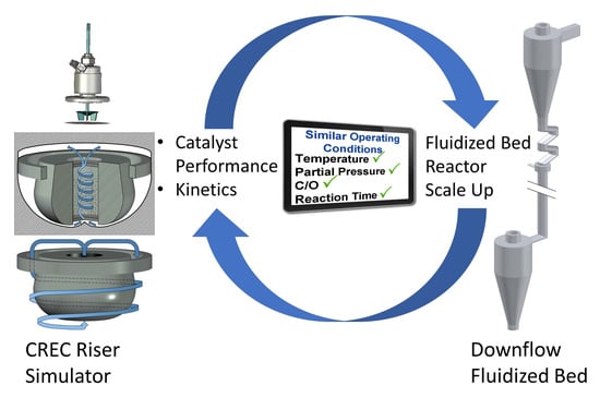
Regarding this matter, it is important to recognize that applicable catalyst testing, and kinetic models must be developed hand in hand with bench scale units that closely emulate the operating conditions of industrial scale processes. In this respect, operating conditions similar to those in large fluid bed reactors such as reactant partial pressures, temperatures, catalyst/reactant weight ratio, and reaction times need to be considered.
To address this matter, in 1992, de Lasa [1] invented a catalytic bench scale reactor, designated as the CREC Riser Simulator. The concept of this new bench scale reactor was to provide a range of operating conditions close to the ones of industrial risers and downer units, as shown in Table 2. Thus, and on this basis, one can assert that this unit provides a proper accounting of environmental reaction conditions for assessment of catalytic reaction rates available for fast fluidized bed scale-up.
In contrast to the special ability of the CREC Riser Simulator to match industrial operation, one can also notice in Table 1 that other bench scale units whether they be MAT (Micro Activity Test)-fixed beds or MAT (Micro Activity Test)-fluidized beds, do not provide accurate riser or downer simulations, given the lack of needed agreement in the range of operating conditions. For instance, for catalytic cracking, the following discrepancies with industrial riser and downer units can be reported: (a) In the MAT, the C/O ratios are defined on a cumulative basis. This is not the case in risers and downers, where the C/Os are established as set values, between incoming catalyst mass flow and reactant mass flow. (b) In the MAT, the catalyst time-on-stream and the gas phase chemical species contact time are significantly different, being in the minute range for the catalyst, versus in the second range for the gas phase chemical species. This is quite dissimilar from the several seconds for both reactant chemical species and catalyst reaction times in downers and risers. (c) In the MAT, the reactant partial pressures are in the 0.05–0.1 atm range, while in risers and downers, they are at the 0.5–0.7 atm level. In addition, and in fixed bed-based MATs, there is non-uniform catalyst activity along the unit length, due to coke formation, as well as the possibility of gas phase channeling occurring, with the gas flow moving in a bed of agglomerated particles, with deficient contacting between phases.
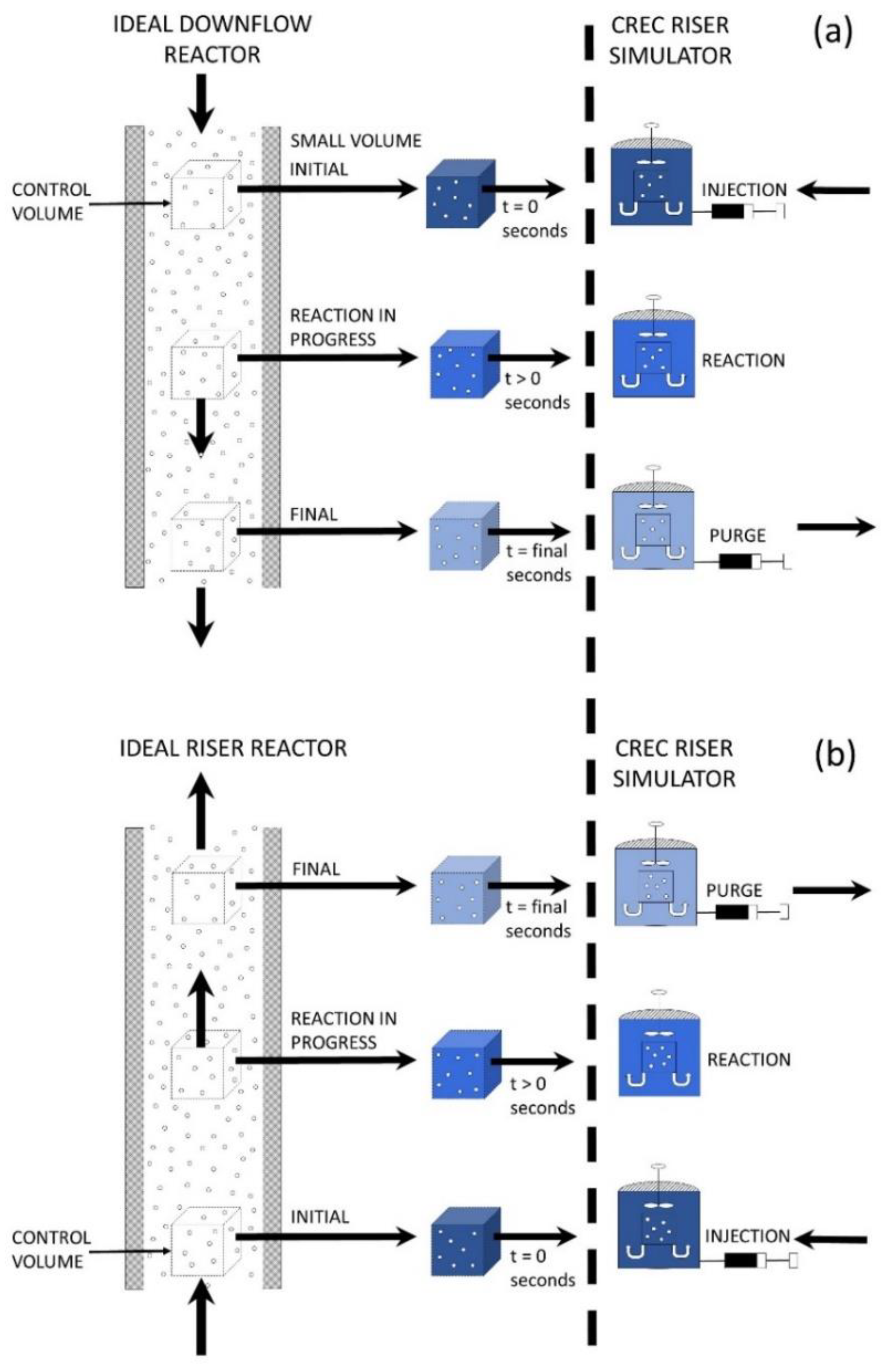
Figure 1a,b, illustrate the chemical species concentration changes in both ideal downer and ideal riser continuous units, by using a moving reactor “control volume”. As shown in Figure 1, chemical species concentration changes in this control volume, with increasing residence time. This can be visualized with color variations, ranging from dark blue to light blue. In addition, on the right-hand side of Figure 1a,b, one can see similar chemical concentration changes with reaction time, occurring in the CREC Riser Simulator, also represented using progressive color variations.
Thus, one can see that the CREC Riser Simulator, as shown in Figure 1a,b, complies with a “first” condition required for proper reactor simulation, which is to provide reaction times, in a fluidized bed with high gas recirculation and solid mixing [10,11,12], that are comparable to those of a moving “control volume” in a riser or in a downer. One should mention that this is achieved in the CREC Riser Simulator, while gas phase chemical species and catalyst are in intimate contact during the entire reaction period.
However, to reproduce the reaction environments of downers and risers in FCC, additional conditions are necessary to be met as described in Table 1, such as having similar temperatures, C/O (catalyst/Oil) ratios and reactant partial pressures. For instance, when simulating FCC (fluidized bed catalytic cracking) units, this is accomplished by operating the CREC Riser Simulator as follows: (a) 510–550 °C temperatures, (b) 3 to 10 s total reaction times, (c) 5 to 7 C/O ratios, (d) 0.5 to 0.7 atm. hydrocarbon partial pressures. Thus, on the basis that these operating conditions are the same in FCC units and in the CREC Riser Simulator, one can claim with certainty that the CREC Riser Simulator provides a true simulation of FCC riser and downers units.
Similar principles of close operating conditions to downer and riser units, as delivered by the CREC Riser Simulator, can be of value to other potential catalytic processes in risers and downers, such as is the case of the catalytic oxydehydrogenation of light paraffins which is further discussed in Section 5 of this review.
The CREC Riser Simulator operates with gas and catalysts displaying the same reaction times. This condition is designated as “ideal riser” or “ideal downer” as shown in Figure 1. This is equivalent to assuming that gas and catalyst residence times both for downers and risers are the same or the equivalent that there is no differential slip velocity between gas and particle velocities. This is proximately true given that catalyst particles and gas phases flow at typical velocities in downers and risers, differing in about 5–10% only. Thus, given residence times are close, one can assume they are equal, a fact that can be acceptable as first approximation. Furthermore, and as described in Table 1 [6,9], the derived CREC Riser Simulator kinetic models require to be also incorporated in CPFD simulations as described in Section 7, and this to have a rigorous description of the continuous riser/downer unit performance.
Therefore, one can conclude that a unit such as the mini-fluidized batch CREC Riser Simulator has significant potential for the development of catalytic processes, given that this unit is able to closely reproduce the reaction environments of large-scale reactor units. This leads to accurate catalyst performance evaluations and relevant kinetic models. These evaluations and kinetic models can be established with small amounts of catalyst in the 1 g range, with this being of special value for the development of new processes with limited amounts of catalyst available.
2. The 1992-CREC Riser Simulator Model and Its Auxiliary Equipment
As stated, earlier [1], the 1992-CREC Riser Simulator is a reactor specially designed to achieve fluidization and batch operation, with high gas phase recirculation. The unit is complemented with several auxiliary equipment components such as valves and a vacuum box, which allow the catalytic reaction to start and to be arrested at a predetermined reaction time, in the 3 to 20 s reaction range.
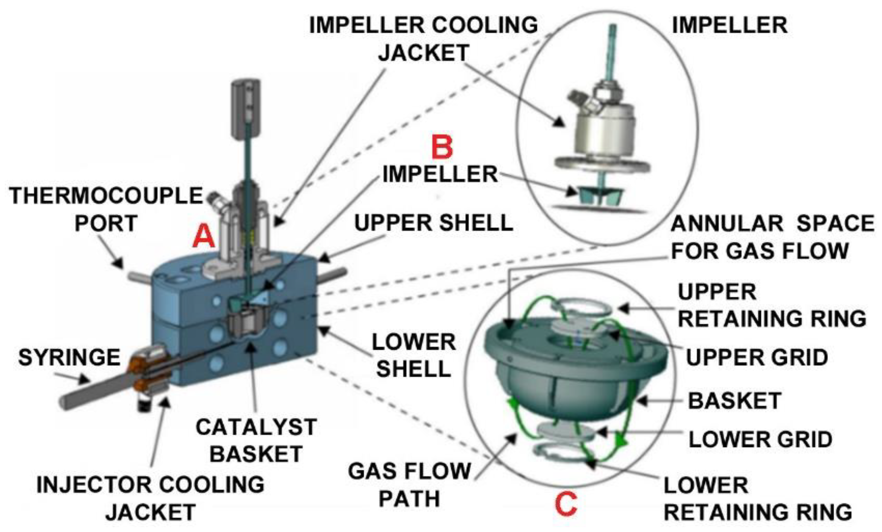
The first 1992-CREC Riser Simulator model [1] described in Figure 2 includes a 50 cm3 reactor, housing a basket where a catalyst can be loaded. The catalyst is contained between two porous grids. An impeller placed in the upper section of the reactor, contributes to high fluid phase recirculation. There is a gas phase upflow through the basket and a gas phase downflow in the outer annular space between the basket and the reactor body.
In the 1992-CREC Riser Simulator, the outer surface of the catalyst basket is engineered with vertical baffles. This transforms the rotational flow induced by the impeller, into a dominant gas phase downflow in the outer annular space, with the catalyst being fluidized at 5500 rpm. Rod heaters, thermocouples, and temperature controllers ensure close to isothermal conditions. The 1992-CREC Riser Simulator is also equipped with a digital pressure gauge which allows the progress of the reaction to be followed via total pressure changes, including those occurring during feedstock vaporization, and reaction and evacuation, with pressure data being recorded every 0.05 s. These pressure gauge measurements are also valuable to evaluate the product transfer towards the analytical section of the CREC Riser Simulator unit, at the end of the reaction period. Thus, the objective of the 1992-CREC Riser Simulator model unit, which was to make available a batch unit with (a) an intensively fluidized catalyst with simultaneous high fluid recirculation, (b) reaction times in the 3–5 s range, (c) quick vaporization and evacuation, (d) suitable temperatures, reactant partial pressures and C/O ratios, was fully achieved.
Regarding mixing, intense catalyst mixing takes place considering a) visual observations using a Plexiglas CREC Riser Simulator bottom section at ambient conditions, and (b) mixing of layered catalyst particles of two colors (e.g., regenerated catalyst and coke catalyst) at reaction conditions. Concerning gas mixing, high gas mixing was established using gas phase tracers with: (a) 0.03s mixing times [10,11] and (b) CPFD computations [12].
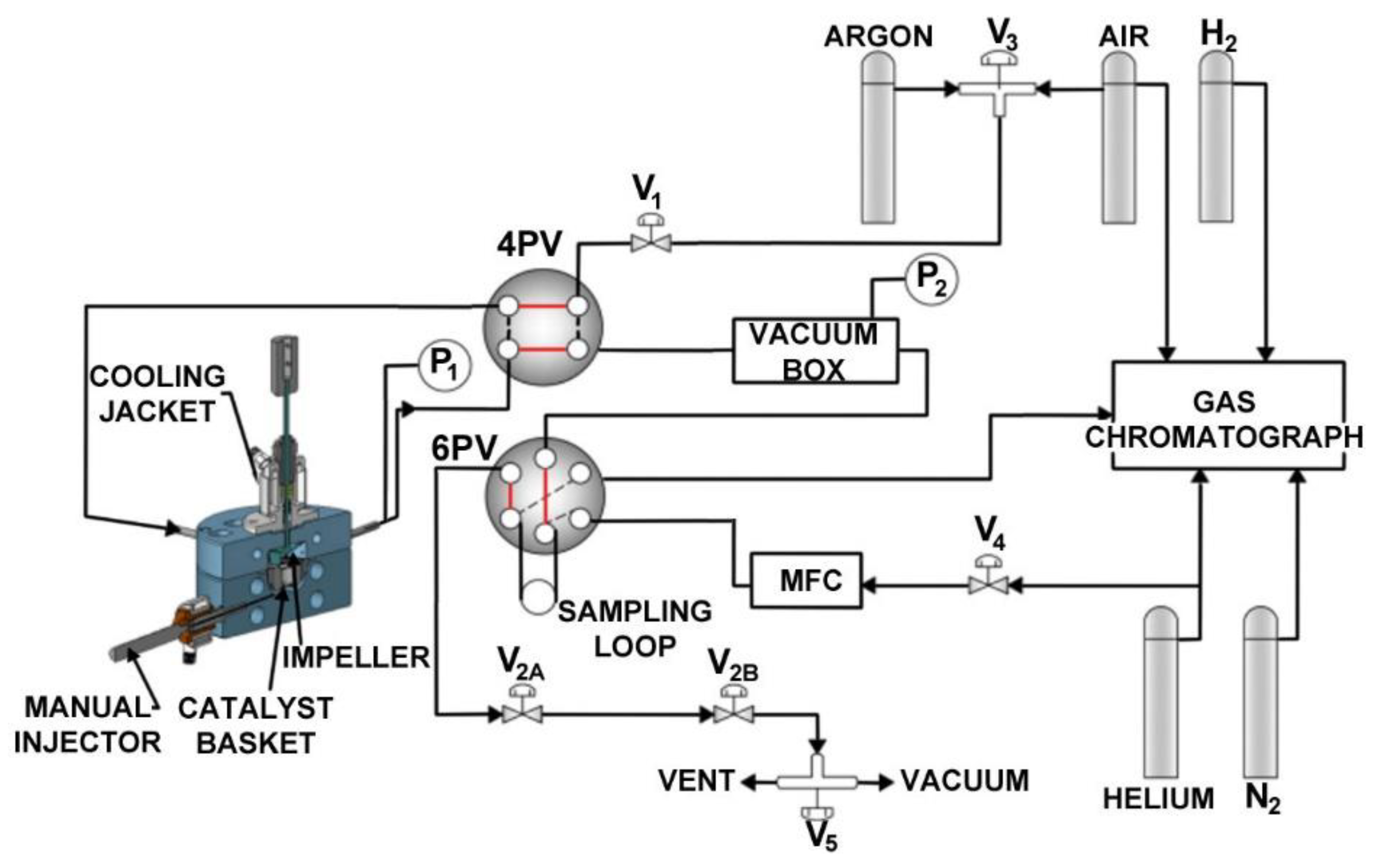
Figure 3 provides a detailed description of the 1992-CREC Riser Simulator auxiliary equipment which includes: a 4 PV, a 6 PV, a vacuum box, a gas chromatographic unit for product analysis, a mass flow controller, temperature controlled heated lines to allow the adequate transfer of the chemical species without condensation, pressure gauges.
The operation of the CREC Riser Simulator includes several preparatory steps prior to the initiation of the run, with the catalyst loaded in the basket [14]. These include (a) combusting any coke-on-catalyst with air, (b) heating the CREC Riser Simulator (e.g., 550 °C), the vacuum box and the various transporting lines to the desired temperatures (e.g., 250 °C), (c) conditioning the catalyst by contacting it with inert gas in order to remove the adsorbed species from a previous run, (d) evacuating the contents of the 1000 cm3 vacuum box, the 6 PV sample loop and the various lines, in order to set them to a desirable low vacuum pressure (e.g., 4 psi), and (e) rotating the impeller at the preset rpm in order to achieve good fluidization.
Once these preparatory steps are completed, the following takes place: (a) feeding of the reactants using an injection syringe, whether they are gases or liquids, with a timer activation to identify the zero-reaction time, (b) development of the run with continuous pressure monitoring, during the entire reaction period (e.g., 5 s), (c) product evacuation from the reactor to the vacuum box, through a 4 VP, at a predetermined reaction time (e.g., 5 s). All these steps are monitored both in the reactor and the vacuum box using pressure gauges. Once the run is complete, the 6 PV opens allowing the inert gas carrier to transport a product sample to the GC unit for analysis.
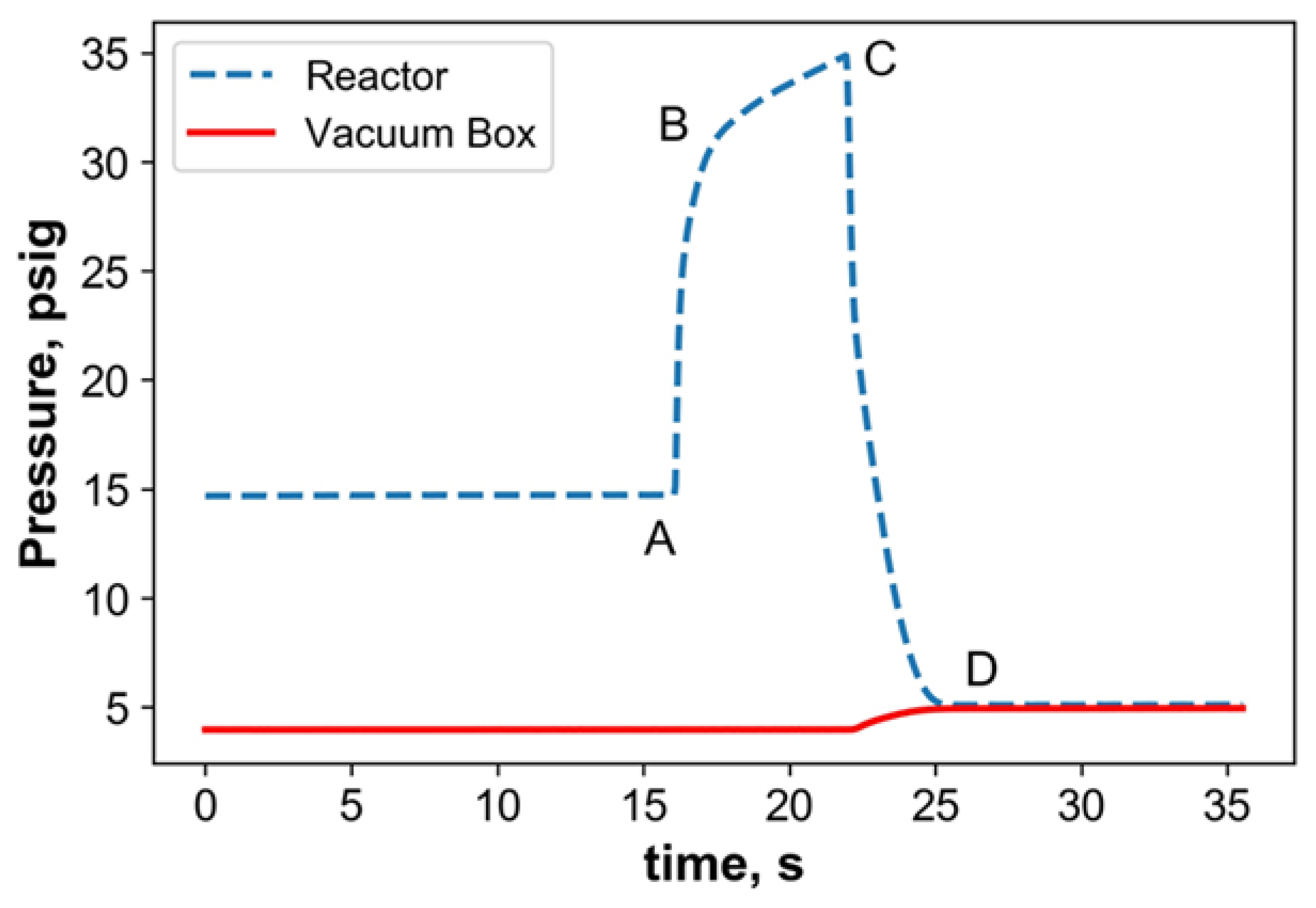
Figure 4 provides a typical example of the pressure profile for the catalytic cracking of tri-isopropyl-benzene (TIPB) in the CREC Riser Simulator. One can observe that injection, reaction, and evacuation times are established accurately on the basis of the pressure profile, with: (i) Condition at A of Condition 1, showing the injection instant or t = 0 time, (ii) Trajectory A to B tracking the feedstock vaporization, (iii) Trajectory B to C describing the total pressure change, as a result of the reaction progress and total molar increase, (iv) Trajectory C to D displaying the sudden chemical species evacuation from the reactor with transfer to the vacuum box. In addition, Figure 4 also provides valuable information on the total pressure, in the 250 °C heated vacuum box, following evacuation. One can notice as well that both reactor pressure and vacuum box pressure reach equal values once the transfer of the reactor chemical species from the reactor unit to the vacuum box is complete.
Reactor operation pressure at C, prior to reactor evacuation is designated alter in mass balance calculations as Condition 2, while reactor pressure at D, following reactor evacuation is designated as Condition 3.
It is important to emphasize that in the 1992-CREC Riser Simulator, mass balances can be performed, as described in Appendix A. This can be done by using as a basis the inert gas (i.e., argon or helium), as well as the various chemical products formed during every run at: (a) zero reaction time, (b) prior to product reactor evacuation, (c) after complete reactor evacuation.
3. Conversion and Selectivity in the 1992-CREC Riser Simulator
Performance parameters for a catalyst under study, in the 1992-CREC Riser Simulator, can be evaluated via the calculation of feedstock conversion, yield and selectivity for a generic “i” species, which could eventually represent a lump of chemical species. In this respect, when using as a case study the catalytic cracking of TIPB, the following equations based on FID-GC areas and coke yields can be considered:
- To determine the TIPB Conversion parameter, the following equation can be used:with = being the chemical species change (excluding coke), β = /Wo representing the coke yield, Wi and WT standing for the “i” product and feedstock weights (excluding coke), respectively, and Ai and AT denoting the FID-GC areas for the “i” product and all FID-GC chemical species detected, respectively.
- 2.
- To calculate the product , representing the “i” product or lump of products over the feedstock weight, the following equation can be used:with being the yield of “i” chemical species (excluding coke).
- 3.
- To establish the , Equations (1) and (2) can be combined as follows:
4. Validation of Collected Experimental Data Using Carbon and Argon Balances
The data obtained in the CREC Riser Simulator can be validated by using the mass balances of the inert gas (i.e., argon) and of the reactants and products. In this respect, three types of mass balances can be performed to validate TIPB catalytic cracking runs: (a) an argon balance (Inert%), with the inert argon being used as an internal standard, to confirm the temperature and pressure measurement reliability, (b) a hydrocarbon balance (Hc1%) prior to the evacuation of the products to the vacuum box, with pressure, temperature and chemical species composition data being obtained from the reactor unit, (c) hydrocarbon balances (Hc2%) following the evacuation of the product species to the vacuum box, and once the reactor and vacuum box pressures are equilibrated. Details of these methods and the equations employed for these balances, are reported in Appendix A.
Appendix A describes both the procedure as well as the typical mass balances obtained in the CREC Riser Simulator, for the cracking of TIPB, using the argon inert gas as an internal standard. Typical results obtained for a series of 16 consecutive TIPB catalytic cracking runs are reported in Figure A1, Figure A2 and Figure A3, with typical balance closures as follows: (a) Inert% argon balance: 100 ± 0.5%, (b) Hc1% hydrocarbon balance prior to evacuation: 100 ± 7.8%, (c) Hc2% hydrocarbon balance once both reactor and vacuum box reached equilibrium: 97 ± 7.3%.
Equal valuable balances can be performed for the catalytic cracking of VGO (Vacuum Gas Oil) for the Inert% balances and Hc2% balances as discussed in Appendix B, including the converted and unconverted VGO fraction. Results of this analysis give for 43 VGO catalytic cracking runs 97% ± 0.5 and 98% ± 7 for Inert% and Hc2% balances, respectively.
Thus, and on this basis, both for TIPB and VGO cracking, one can assert that the CREC Riser Simulator provides experimental data with the proper mass balance closures, as required for good data validation.
5. Kinetic Modeling in the 1992-CREC Riser Simulator
The CREC Riser Simulator is designed to achieve both good fluidization under isothermal conditions, and batch operation with high gas recirculation. This leads to catalyst operation being free of external mas transfer limitations [13], quasi-constant concentration of chemical species at any reaction time [10,11,12], uniform catalysts deactivation. These operating conditions with close partial pressures than in the riser and downer units, lead to relatively simple ordinary differential equations, based on “key chemical species” balances, with chemical changes occurring in these species with increasing reaction time, at “quasi” constant temperatures, as is represented in the following equation:
with Ci representing the concentration of the “i” chemical species in Kmole/cm3, ri standing for the catalytic reaction rate in Kmole/Kgcat s, W denoting the weight of catalyst in kg, Vr representing the reactor volume in cm3, and and η standing for the catalyst deactivation function and the η effectiveness factor parameter, respectively.
The resulting kinetics studied in the CREC Riser Simulator can be affected by the intrinsic reaction, the chemical species adsorption and desorption, and the chemical species diffusivity, with all these effects being included in (a) the ri catalytic reaction rate, (b) the intraparticle or/and intracrystallite diffusion, accounted for via an η effectiveness factor, and (c) the catalyst deactivation, represented via a deactivation function. It is important to state that other potential phenomena such as the external particle mass transfer, can be disregarded from the modeling, given the small catalyst particle size used in fluid bed units, and the high gas velocities promoted by the high gas recirculation in the Riser Simulator.
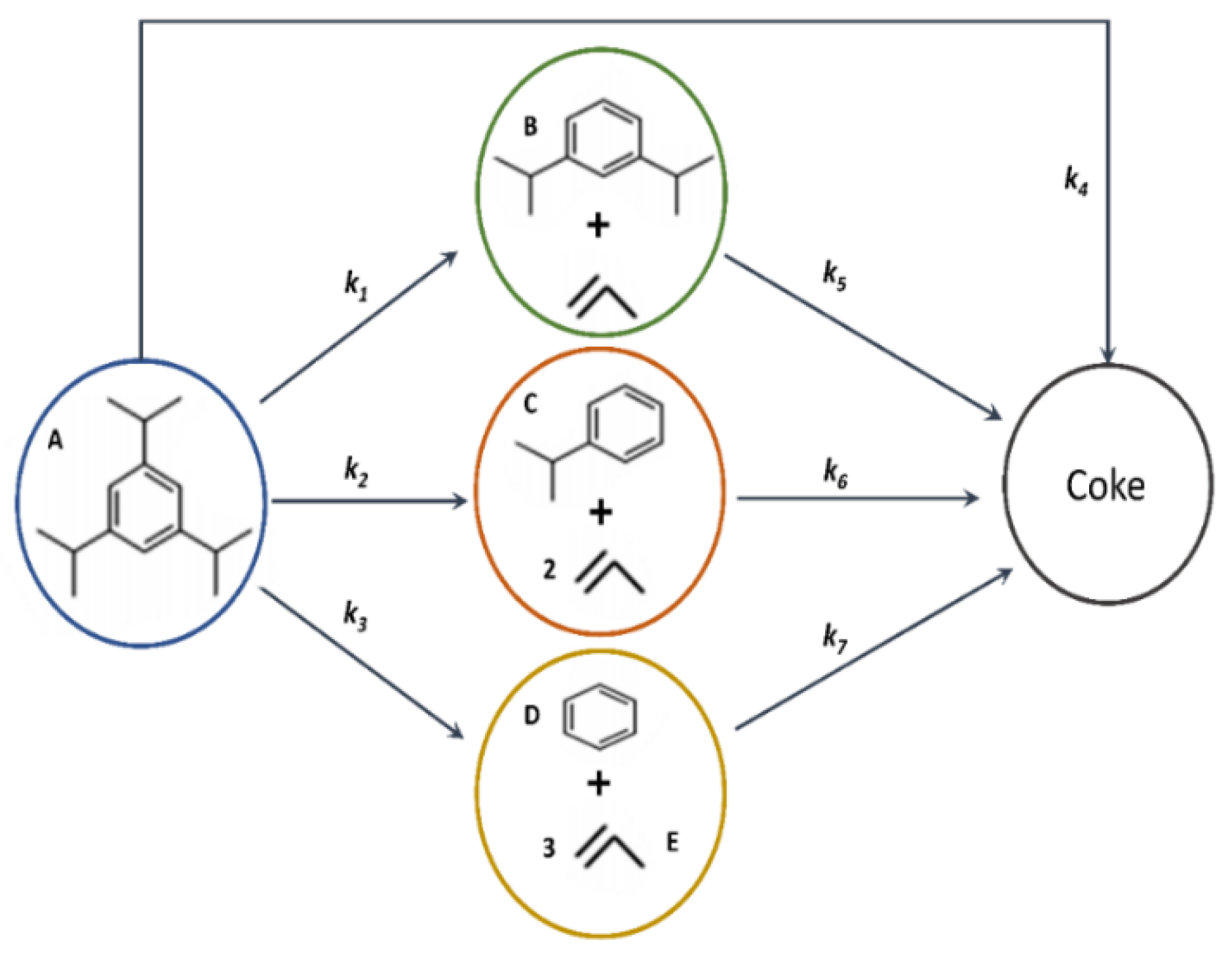
To take advantage of the experimental data obtained in the CREC Riser Simulator and of the resulting Equation (4), a reaction network must be postulated. This reaction network must be consistent with the experimentally observed chemical species (reactants and products) and the chemical thermodynamics constraints. For instance, in the case of the catalytic cracking of the TIPB model compound, a chemical species including a good balance of aromatic and iso-paraffinic functionalities, can be used for a postulated reaction network, as described in Figure 5.
Based on the postulated reaction mechanism shown in Figure 5 and represented in Equation (4), chemical species changes can thus be described as follows:
where CA, CB, CC, CD, CE represent the gas phase concentrations of various chemical species, qc stands for the coke concentration on the catalyst, α, k1, k2, k3, k4, k5, k6 and k7 denote the kinetic parameters of the proposed reaction network, and η1, η2, η3 represent the effectiveness factors for Steps 1, 2 and 3 of the proposed reaction network, respectively.
With the experimentally data obtained chemical species concentrations and coke at various temperatures, reaction times, total pressures, and coke, allows one to evaluate the postulated model to TIPB catalytic cracking in the CREC Riser Simulator. To accomplish this, simplifications are permitted which disregard the k5, k6 and k7 parameters. This has allowed the CREC research team to quantify the unique and previously not described influence of the C/O ratio on hydrocarbon catalytic cracking conversion, as reported in Table 3 [14].
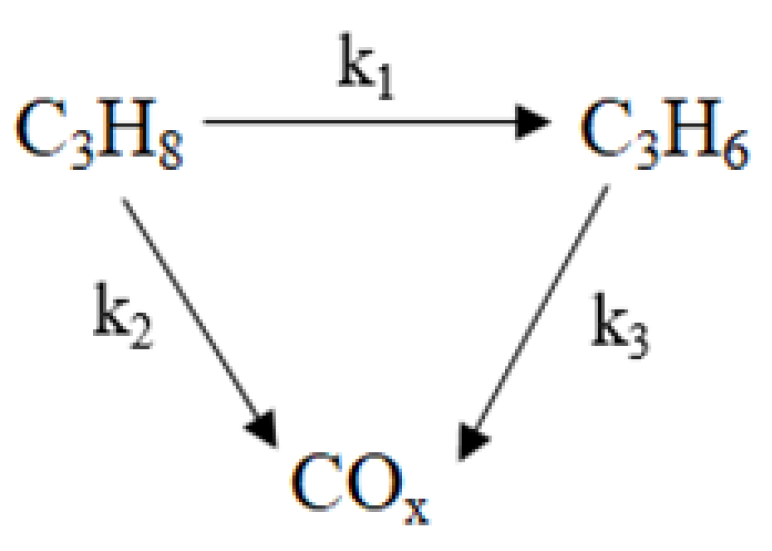
A similar approach was used by the CREC research team [16] for the catalytic oxydehydrogenation of propane (ODHP) under gas phase oxygen free conditions, with the following reaction network being postulated as described in Figure 6:
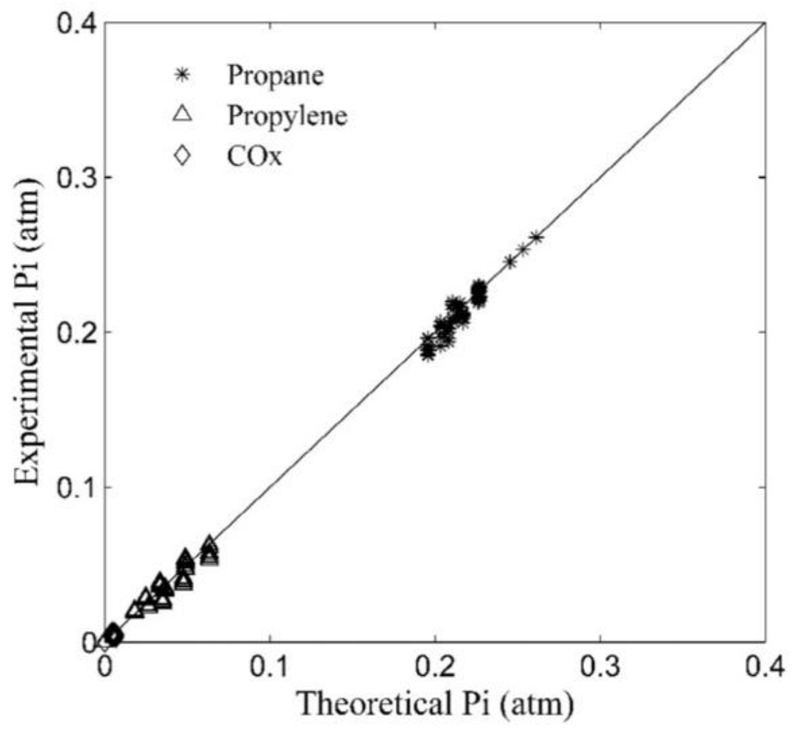
For the PODH postulated reaction, the partial pressures of various chemical species obtained in the CREC Riser Simulator, were compared with the partial pressures resulting from the numerical solution of Equation (4). This evaluation is reported in Figure 7, with a best set of adjusted kinetic parameters that have reduced spans and low cross-correlation. This is also reported in Table 4.
Thus, both the catalytic cracking of TIPB and PODH provided examples that attest to the importance of the CREC Riser Simulator for the assessment of both kinetic models and kinetic parameters, under operating conditions close to the ones of riser and downer units.
6. Recent Advances with the Improved 2019-CREC Riser Simulator
Despite the significant value of the CREC Riser Simulator for the evaluation of promising catalysts and suitable kinetic models, enhancements were introduced in the design of the CREC Riser Simulator unit in 2019 [2] as follows: (a) improved basket design using a frustoconical shape, (b) High-Performance Filter Condenser (HPFC) and a Canister Filter Condenser (CFC), (c) in situ enhanced MIR (Medium InfraRed) for online measurement of chemical species.
6.1. Improved Flow Patterns with Basket Frustoconical Shape
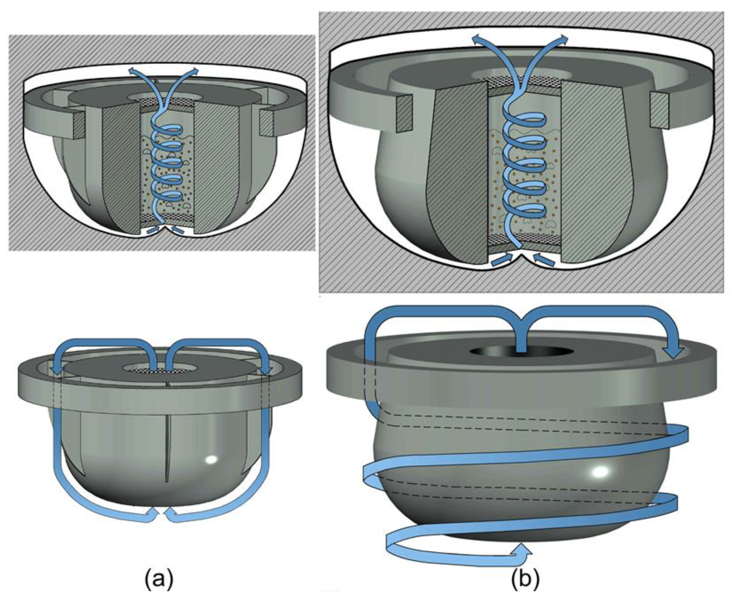
CFD simulations of the 1992-CREC Riser Simulator, described in Figure 8a [12], showed that the vertical baffles placed in the outer reactor annulus created an impediment to the required beneficial circumferential flow in the unit. The vertical baffles made it necessary for the reactor impeller to be operated at 5400 rpm to achieve good particle fluidization. This stringent operating condition created several mechanical problems, including difficulties with impeller stability at these high rpm rotations. As a result, it was considered preferable to exclude the vertical baffles from the 2019-CREC Riser Simulator basket design, as described in Figure 8b.
Figure 8b depicts the circumferential promoted streamlines both internal and external to the unit, as proposed in the 2019-CREC Riser Simulator model [12]. In addition, and to provide a major enhancement to these favorable fluid dynamic conditions, low pressure drop porous grids and a reshaped frustoconical basket, as shown in Figure 8b, were adopted. This frustoconical reshaped basket provides a progressive velocity increase in the bottom section of the unit, favoring catalyst fluidization at lower impeller rotational speeds. For instance, for a typical fluidizable FCC catalyst with a 60-micron average particle diameter, the required impeller rotational speed for good fluidization was reduced from 5400 rpm in the 1992-CREC Riser Simulator to 4200 rpm in 2019-CREC Riser Simulator.
In summary, the proposed 2019 enhancements allow the operation of the CREC Riser Simulator at lower impeller rotational velocities. Consequently, there are, in the 2019-CREC Riser Simulator reduced mechanical issues with impeller stability, as well as a diminished wear of the impeller supporting cones. As a result, these improvements extend the efficient operation of the CREC Riser Simulator, with less required maintenance.
6.2. High Performance Filter Condenser (HPFC) and Canister Filter Condenser (CFC)
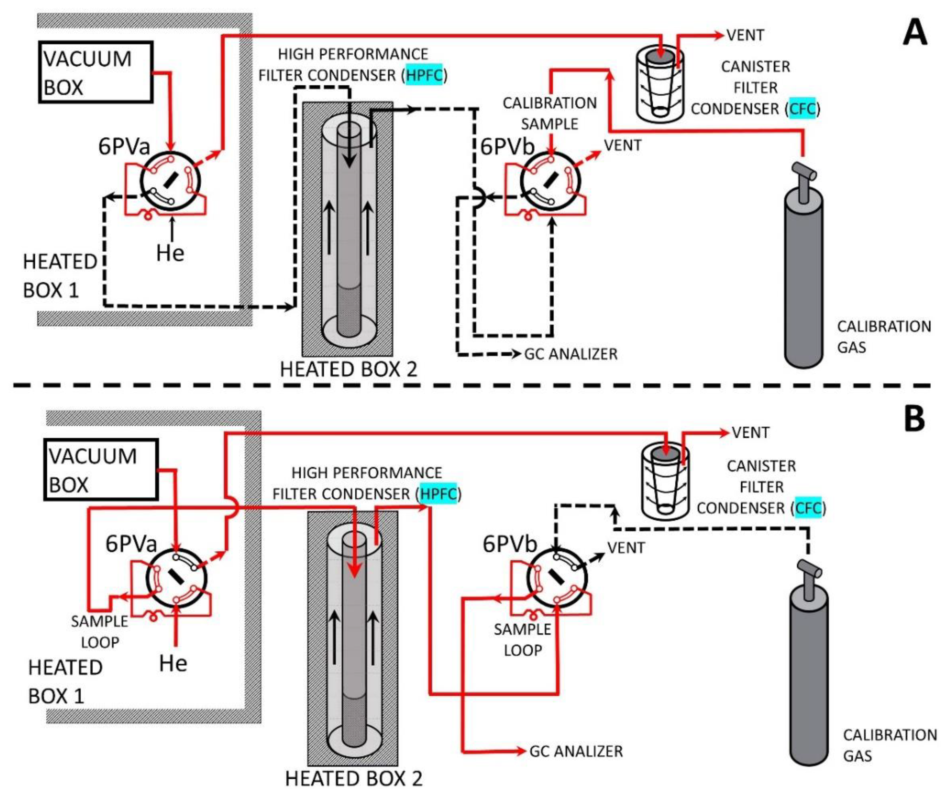
As stated in the previous sections, the 1992-CREC Riser Simulator accurately reproduces the full range of operating conditions for accurate catalyst testing and kinetic modeling. Despite these advantages, the 1992-CREC Riser Simulator application for the evaluation of the catalytic cracking of VGO (vacuum gas oil) faced challenges, given the condensation of heavier than C16 hydrocarbon product in the 230 °C heated transfer lines. This altered the GC analysis and the VGO conversion calculations. To address this matter, two additional auxiliary components were implemented in the 2019-CREC Riser Simulator unit, as shown in Figure 9A,B: (a) a High-Performance Filter-Condenser (HPFC) placed very close to the 6 PV, (b) a Canister-Filter Condenser (CFC) located in the transfer exhaust vent line. The combined operation of both the HPFC and CFC allows one to remove from the carrier gas all hydrocarbons with a carbon number larger than sixteen. As a result of this, hydrocarbons with carbon number smaller than sixteen, representative of the formed products are analyzed via GC, while hydrocarbons with carbon number larger than sixteen, representative of the unconverted VGO fraction, are collected in the CFC for separate characterization.
Figure 9A,B describe the two possible operational steps of the CREC Riser Simulator auxiliary system. In Step A, the product gas from the vacuum box, flows out through the 6 PVa to the CFC. In Step B, at the time the 6 PVa is rotated, the product sample is carried out by the helium flow, from the vacuum box, through the 6 PVa loop, towards the GC Analyzer. This occurs after all condensable products (>C16 hydrocarbons) are removed in the HPFC. The HPFC is operated at 150 °C, as required to achieve dew point conditions for all hydrocarbon > C16 hydrocarbon fractions.
Furthermore, and as shown in Figure 9, in Step B, the 6 PVb placed on top of the GC analyzer, ensures that a known volume of a calibrated methane gas sample is also included as a separate early peak (internal standard) in every chromatogram. To accomplish this, the 6 PVb is activated in advance to the 6 PVa, securing in this manner an early calibration methane peak which does not interfere with any of the C1–C16 product species.
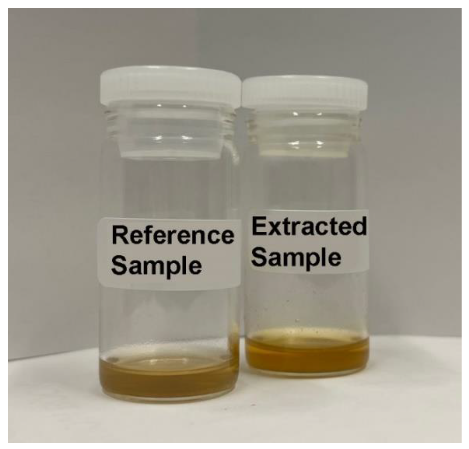
Figure 10 shows the high efficiency of the proposed CFC collecting all the vacuum box sample contents larger than C16 hydrocarbons. The octane extract from the CFC from two repeat runs display close colors than a reference sample prepared with 1 drop of VGO in octane. Thus, amounts of CFC collected samples are valuable for a further chemical characterization of the reaming unconverted VGO fraction.
Therefore, by integrating a HPFC in the CREC Riser Simulator auxiliary equipment, in every VGO cracking run, good GC analysis data (light gases, gasoline, cycle oil) can be obtained. This can be accomplished with a minimum influence of the larger than C16 condensable fractions, not able to flow through the condenser and reach the GC unit. With the pressure and temperature data obtained from the CREC Riser Simulator reactor and the vacuum box, one can calculate the overall feedstock conversion and lump selectivities, as well as to perform trustable mass balances, as described in Appendix B.
6.3. MIR (Medium InfraRed) Measurements in the 1992-CREC Riser Simulator
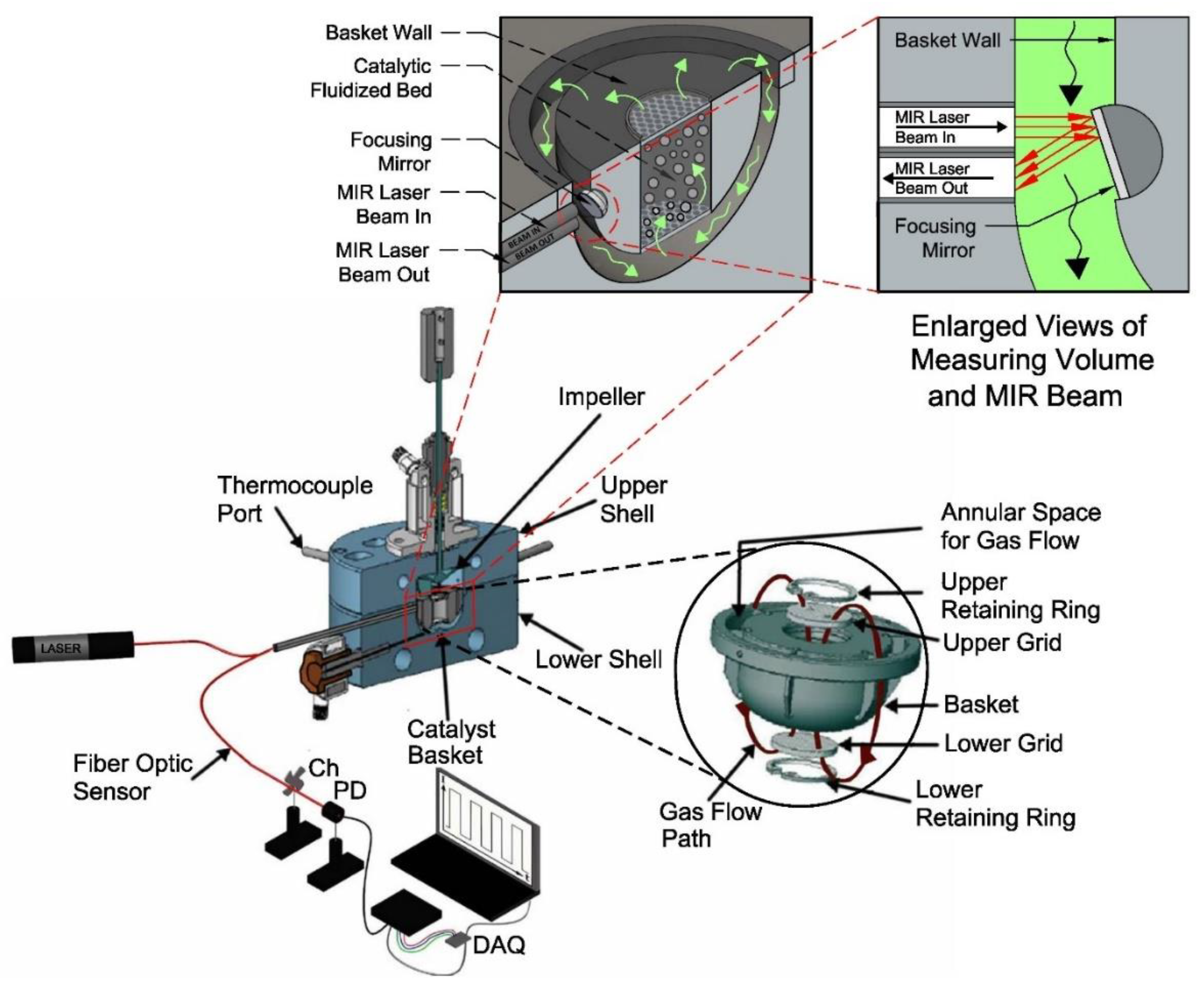
In 2018, an adaptation of the measurement equipment used with the CREC Riser Simulator, based on a Group Contribution Method (GCM), was implemented, and reported [17,18], as shown in Figure 11. It was proposed to strategically place optical fibers, in the CREC Riser Simulator annulus, with a HeNe laser selected as a light source. When using this approach, it was shown that optical measurements could be obtained in the MIR (Medium Infrared) range, free of catalyst particle interference. This was the case given that catalyst particles were contained in the catalyst basket during the reaction, with MIR measurements being performed in the annular region of the CREC Riser Simulator. This allowed one to obtain the experimental data required for assessing the 1, 3, 5, TIPB conversion continuously, throughout the reaction period. These results helped validate and confirm the good reliability of the proposed MIR-GCM (Medium Infrared-Group Contribution Method) method. The GCM-MIR method does not require calibration and provides a host of valuable data from every run. The data obtained can also be employed to establish gas phase hydrocarbon molar densities, at various reaction times.
It can be also anticipated that the data obtained in the CREC Riser Simulator with the adapted fiber optic system for Direct MIR measurements will be valuable for accurate computational fluid dynamic calculations that account for the catalytic FCC activity in continuous risers and downers, where one requires precise estimation of gas phase fluid molar densities along the reactor length.
7. CREC Riser Simulator Applications
Table 5 summarizes the diversity of scenarios in which the Riser Simulator was employed as well as its successful application by several research groups and laboratories around the world including mixing studies and process applications.
Thus, and as documented in Table 5, the CREC Riser Simulator has been applied successfully to a diversity of catalytic and heterogenous processes including (a) the catalytic cracking of hydrocarbons [19,20,21,22,23,24,25,26,27,28,29,30,31,32,33,34,35,36,37,38,39,40,41,42,43,44,45,46,47,48,49], (b) the catalytic conversion of biomass derived tars [50,51,52,53,54,55,56,57,58,59], (c) catalytic desulfurization of gasoline [60,61,62,63,64,65,66], (d) chemical looping combustion [67,68,69,70,71,72,73], (d) oxydehydrogenation of light paraffins [74,75,76,77,78,79,80,81,82,83,84], (e) catalytic steam and dry reforming of methane [85,86,87,88,89], and (f) MTBE synthesis [90]. Table 5 also shows the ability of this unit to contribute to both catalyst performance evaluations as well as to kinetic modeling, using phenomenologically based rate equations. Therefore, and on the basis of its broad demonstrated applicability, one can conclude that the CREC Riser Simulator unit has the potential to become an effective and unique tool for the development of catalysts and the evaluation of riser and downer reactors in the years to come.
8. Conclusions and Future Perspectives
Catalytic fast fluidized beds, and very especially riser and downer units have the potential to provide the required reaction environments for catalytic chemical reactions in reactors with high flow throughputs, high yields of desirable products, low energy consumption, and consequently low CO2 emissions. In fact, catalytic processes based on the use of fast-moving fluidizable catalyst particles allow the shortening of reaction time, in many cases, with these small particles operating free of chemical species diffusional transport limitations.
It is shown in this review that the mini-fluidized CREC Riser Simulator provides a unique tool to study gas-solid catalysts involving reaction times lasting several seconds, as required in downer and riser units. As shown in Table 5, the CREC Riser Simulator, with its high gas phase recirculation and catalyst mixing in the basket confined space [3,4,5], can be applied to a diversity of catalytic processes, with evaluation of rate equations. All this is achieved under operating conditions that mimic the reactor environments of risers and downers in terms of temperatures, reactant partial pressures, C/O ratios and reaction times. The CREC Riser Simulator provides experimental results that can be validated via chemical species balance closure showing that the data obtained are trustable to evaluate catalyst performance and kinetic rates.
A typical example of the ability of the CREC Riser Simulator to identity key catalyst performance issues in riser units is the recent work developed by de Lasa’s research team [21]. It is proven in these studies that the CREC Riser Simulator allows one to identify and establish the critical role of the C/O ratio in FCC units, with an optimum C/O ratio value being determined [21].
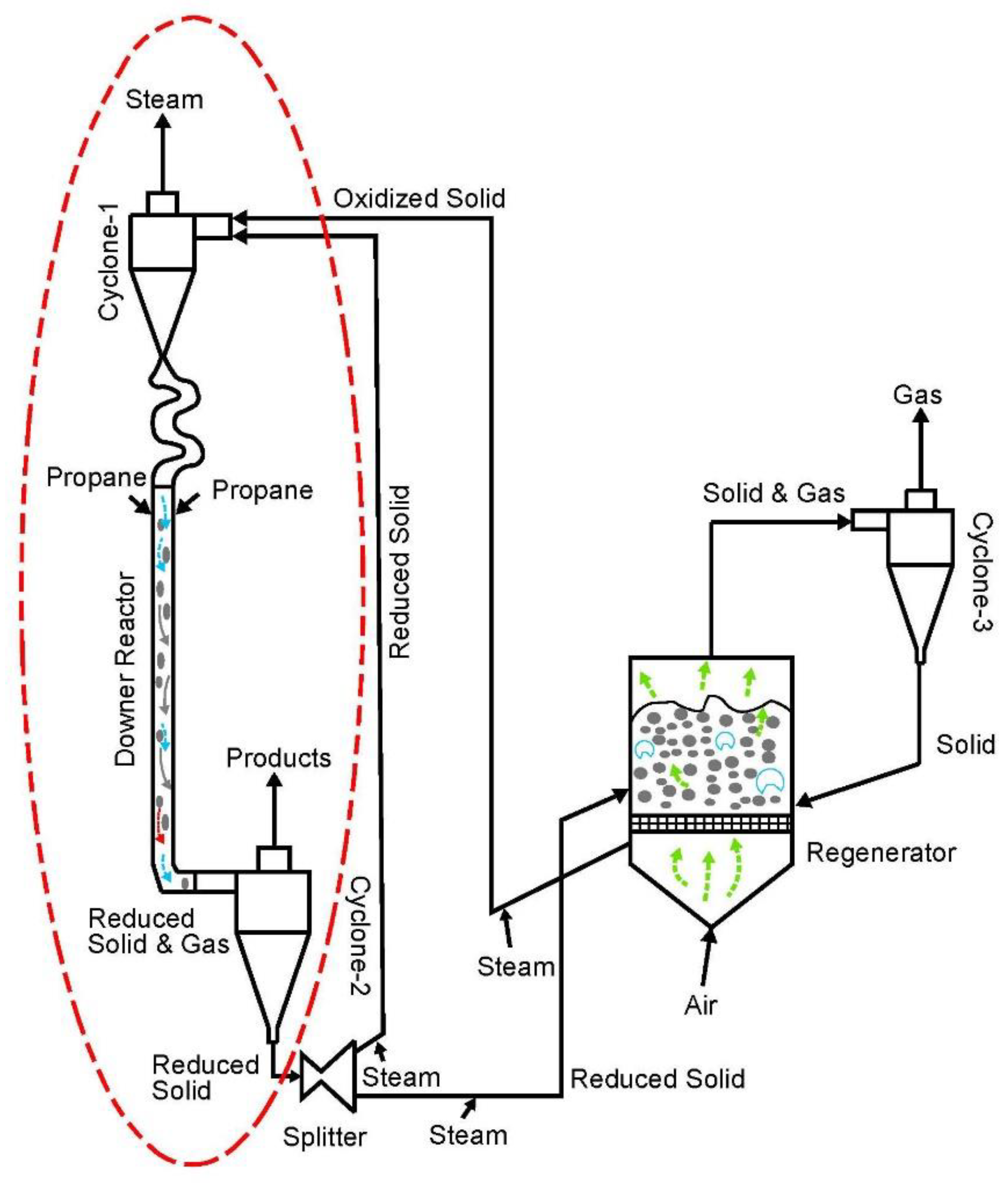
Furthermore, it is anticipated that the availability of these phenomenologically based reaction rate equations will create new opportunities for accurate process simulations, using CPFD software, where riser and downer process unit operation, at large industrial scales, can be reproduced and studied numerically. A successful example of combined CREC Riser Simulator kinetics and CPFD simulation is the PODH, as reported in Figure 12 [84].
Figure 12 describes a proposed PODH process using a set of two fluidized bed reactors. The PODH using lattice oxygen is performed in a downer reactor, while the catalyst reoxidation occurs in a dense phase fluidized regenerator. Propane is fed via two levels of injectors at the downer entry section level where it meets the PODH catalyst. It is in this downer unit where the PODH reactions take place, as predicted with the kinetics established in the CREC Riser Simulator [84]. Then, the partially reduced catalyst enters a cyclone where product gases and catalyst particles are separated. Following this, the catalyst particles exiting the cyclone move into a splitter unit, where the catalyst flow is divided into two streams: (a) a major stream which is recirculated back to the downer directly, and (b) a small stream which is directed to the regenerator for catalyst reoxidation.
It is on the basis of this CPFD simulation which includes the trustable kinetics obtained in the CREC Riser Simulator, that PODH with a high 10/1 split ratio, 28% propane conversion and 93% propylene selectivity is demonstrated to be a viable process option [82].
In summary and given the above, one can anticipate that this combined analysis of prospective catalytic processes involving trustable rate equations obtained in the CREC Riser Simulator and studied with CPFD simulation data will contribute significantly in the near future to the engineering and implementation of new green catalysts and catalytic processes at large industrial scales.
Funding
This research was funded by the Natural Science and Engineering Research Council of Canada (NSERC), through the Hugo de Lasa’s NSERC Discovery Grant.
Data Availability Statement
Not applicable.
Acknowledgments
The author would like to specially acknowledge Florencia de Lasa for her assistance with the editing of this manuscript and the preparation of several figures and the graphical abstract.
Conflicts of Interest
The author declares no conflict of interest.
Nomenclature
| Notation | |
| FID-GC area for “i” chemical species | |
| Adjusted area using Equation (A14) | |
| Refer to Equation (A16) | |
| Adjusted | |
| 1, 3, 5 TIP area used as a reference. | |
| concentration of “i” species with I = A, B, C, D, E, F (Kmole/cm3) | |
| Condition 1 | At injection condition |
| Condition 2 | Prior to evacuation |
| Condition 3 | After evacuation |
| Conversion | |
| Energy of activation for j reaction step (kJ/Kmole) | |
| Hydrocarbon Balance Closure at Condition 2, percentual basis (-) | |
| Hc2% | Hydrocarbon Balance Closure at Condition 3, percentual basis (-) |
| Inert balance closure at Condition 3, percentual basis (-) | |
| frequency factor for 1, 2, 3, 4, 5, 6, 7 reaction steps (1/s) | |
| apparent frequency factor for 1,2, 3 reaction step (1/s) | |
| Molecular Weight of inert (kg/Kmole). | |
| Hydrocarbon average molecular weight (kg/Kmole). | |
| Molecular weight of hydrocarbons at injection: Condition 1 (kg/Kmole) | |
| Molecular weight of hydrocarbons prior to evacuation: Condition 2 (kg/Kmole) | |
| Molecular weight in the reactor and in vacuum box after evacuation: Condition 3 (kg/Kmole) | |
| MWCHn,TIPB | Molecular weight ofthe CHn unit for TIPB (kg/Kmole) |
| MWCHn,VGO | Molecular weight of the CHn unit for VGO (kg/Kmole) |
| Molecular weight of vacuum gas oil | |
| Moles of hydrocarbons at injection condition: Condition 1 (Kmole) | |
| Moles of hydrocarbons in reactor prior to evacuation: Condition 2 (Kmole) | |
| Moles of hydrocarbons after evacuation: Condition 3 (Kmole) | |
| Moles of hydrocarbons in reactor at injection: Condition 1 (Kmole) | |
| Moles of hydrocarbons in reactor after evacuation: Condition 3 (Kmole) | |
| Moles of hydrocarbons in vacuum box after evacuation: Condition 3 (Kmole) | |
| Combined moles of inert in the reactor and vacuum box after evacuation: Condition 3 (Kmole) | |
| Moles of inert in the reactor at injection condition: Condition 1 (Kmole) | |
| Moles of inert in the vacuum box at injection condition: Condition 1 (Kmole) | |
| Moles of inert in reactor prior to evacuation (Kmole). | |
| Moles of inert in vacuum box after evacuation (Kmole) | |
| Equilibrium total pressure in reactor ad vacuum box, after evacuation: Condition 3 (atm) | |
| Total pressure at injection (atm) | |
| Inert gas total pressure in reactor, prior to hydrocarbon injection: Condition 1 (atm) | |
| Inert gas total pressure in vacuum box prior to evacuation: Condition 1 (atm) | |
| Inert gas total pressure in vacuum box after evacuation: Condition 3 (atm) | |
| Total pressure in reactor after hydrocarbon injection (atm): Condition 1 (atm) | |
| Total pressure in the reactor prior to evacuation: Condition 2 (atm) | |
| Coke concentration (gcoke/gcatalyst) | |
| Reaction rate for j step (Kmole/kgcat·s) | |
| Universal gas constant (atm·cm3/mole K) | |
| Yield/Conversion (-) | |
| Reaction time (s) | |
| Temperature in the reactor (K) | |
| Temperature in the Vacuum Box (K) | |
| Volume reactor (cm3) | |
| Volume vacuum box (cm3) | |
| Weight of catalyst (kg) | |
| Mass of coke formed (kg) | |
| Mass of hydrocarbons in reactor at time zero: Condition 1 (kg) | |
| Mass of hydrocarbons in reactor at “t” time prior to evacuation: Condition 2 (kg) | |
| Mass of hydrocarbons in reactor at “t” time prior to evacuation, including coke (kg) | |
| Mass of hydrocarbons in reactor and vacuum box after evacuation: Condition 3 (kg) | |
| Mass of hydrocarbons in reactor and vacuum box after evacuation, including coke (kg) | |
| Mass of i species (kg) | |
| Mass of inert gas in reactor at injection: Condition 1 (kg) | |
| Mass of inert gas in reactor at “t” total reaction time: Condition 2 (kg). | |
| Mass of inert gas remaining in the reactor after evacuation: Condition 3 (kg) | |
| Total mass of inert gas in reactor and vacuum box after evacuation: Condition 3 (kg) | |
| Weight of VGO sample injected (kg) | |
| Weight of pure 1, 3, 5 TIP analyzed and used as a reference (kg) | |
| Chemical species weight fractions as | |
| Greek Symbols | |
| (-) | |
| deactivation constant (kgcat/kgcoke) | |
| β | |
| FID-GC calibration factor for “i” species | |
| FID-GC calibration factor for the entire slate of products and reactants | |
| Catalytic deactivation function (-) | |
| γ | Methane area peak from 6 PVb loop over average several methane peaks from 6 PVb loop |
| Ratio of molecular weight of CHn unit in TIPB over molecular weight of CHn in VGO | |
| frequency factor for the j step (-) | |
| Acronyms | |
| C/O | Catalyst/Oil Ratio |
| CPFD | Computerized Particle Fluid Dynamics |
| CREC | Chemical Reactor Engineering Centre |
| MAT | Micro Activity Test |
| MTBE | Methyl-Ter-Butyl-Ether |
| PODH | Propane Oxidative Dehydrogenation |
| TIPB | Tri-isopropyl-benzene |
| VGO | Vacuum gas oil |
| 4PV | Four port valve |
| 6 PV | Six port valve |
| 6 PVa | Six port valve in the auxiliary heat vacuum chamber |
| 6 PVb | Six port valve in the 2019-CREC Riser Simulator auxiliary system for methane calibrations |
Appendix A. Validation of Hydrocarbon Catalytic Cracking of TIPB Runs in CREC Riser Simulator via Mass Balances
Experimental runs developed with the CREC Riser Simulator using model compounds such as in the case of the catalytic cracking of TIPB, can be validated using mass balances developed as follows:
- Mass balances of hydrocarbons and inert gas at hydrocarbon injection time or Condition 1:
- 2.
- Mass balances of hydrocarbons and inert gas at the “t”, total reaction time:
- ●
- Mass balances at “t” reaction time or Condition 2 prior to evacuation:
- ●
- Mass balances at t = teq” or Condition 3, following product evacuation from the reactor:
α=
- 3.
- Inert and hydrocarbon balance closure:
Thus, mass balance closures can be established simultaneously for: (a) the inert gas (Inert%), (b) the hydrocarbons (Hc1% and Hc2%). These three balances (Inert%, Hc1% and Hc2%) are good indicators of data reliability.
The Inert% balance can be used as an internal standard to check the adequate operation of the pressure gauge and thermocouple measurements while the Hc1% and Hc2% can be employed to evaluate the consistency of product composition, established using gas chromatography for various runs.
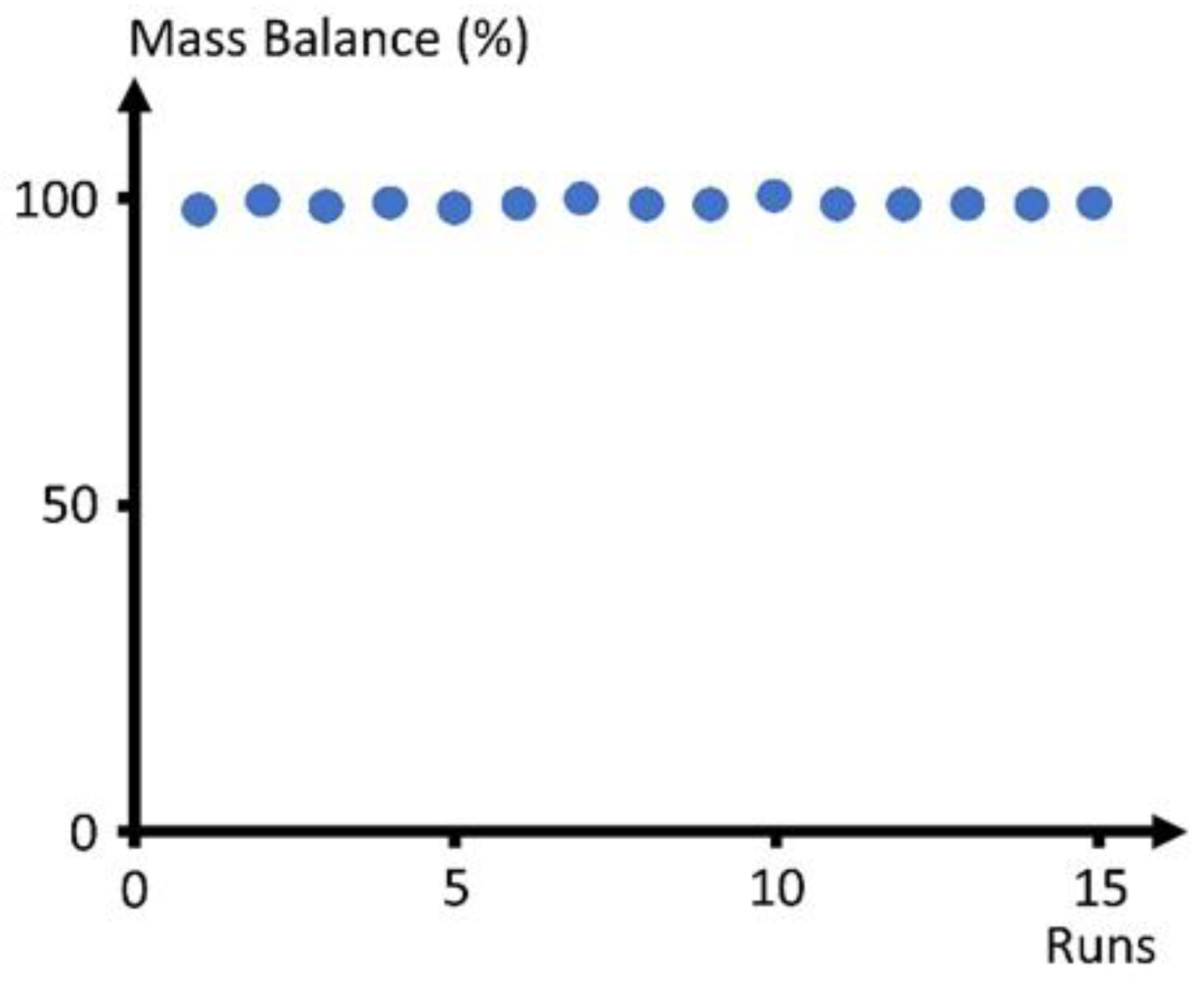
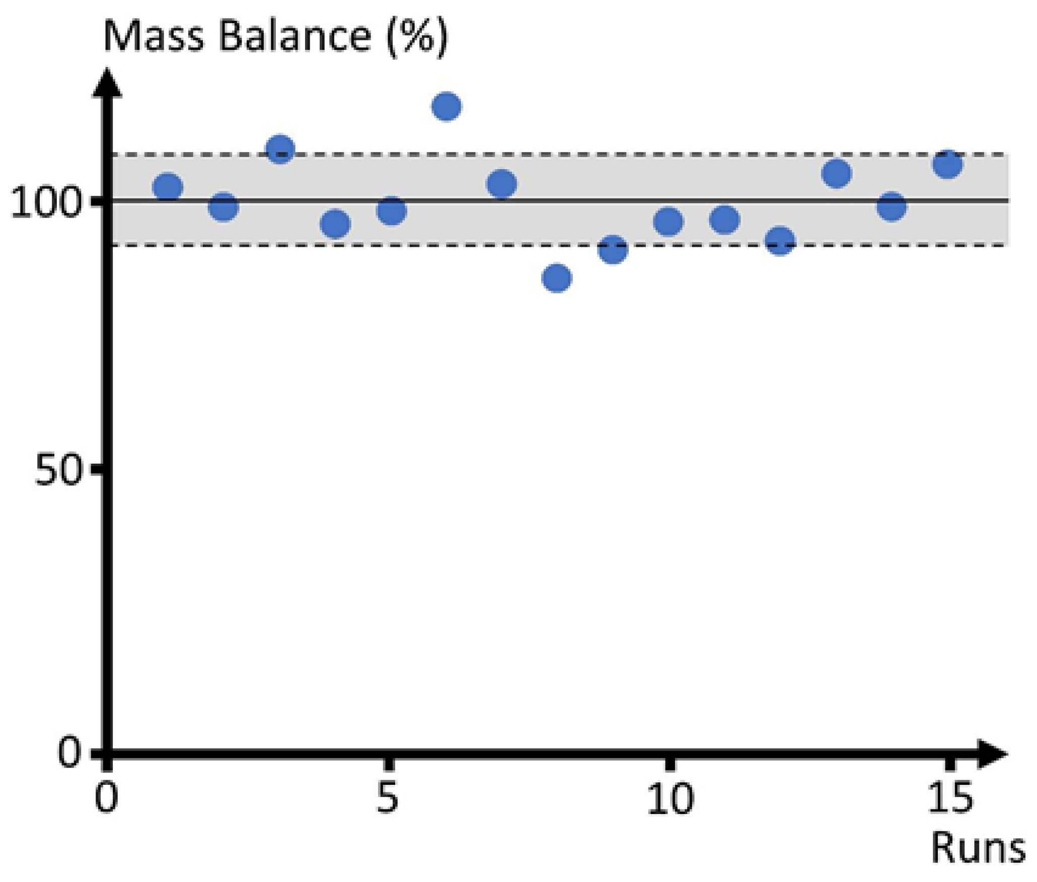
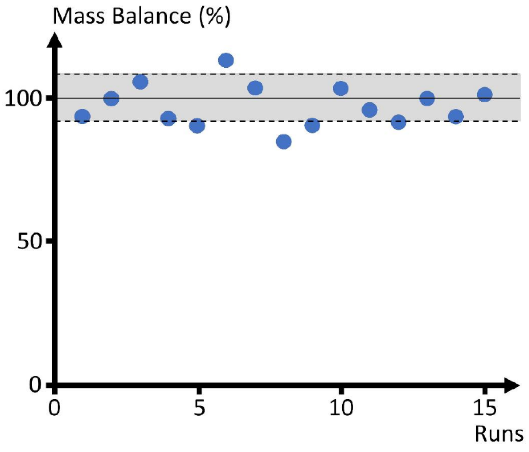
Figure A1, Figure A2 and Figure A3 report the Inert%, Hc1% and Hc2% balances, respectively using Equations (A1)–(A13). It can be observed that for a series of 15 consecutive TIPB catalytic cracking runs performed at 510–530 °C, 3–7 s, and 0.6–5 C/O ratios, mass balance closures yield the following: (a) an argon balance: 100 ± 0.5%, (b) a hydrocarbon balance prior to reactor evacuation: 100 ± 7.8% (Condition 2), (c) a hydrocarbon balance following reactor evacuation with total pressure reaching equilibrium: 97 ± 7.3%.
Figure A1.
Inert% Mass Balances for 15 Catalytic Cracking Runs of 1, 3, 5-TIPB Using the Method Described in Appendix A. Condition 3, Standard Deviation: ±0.5%.
Figure A1.
Inert% Mass Balances for 15 Catalytic Cracking Runs of 1, 3, 5-TIPB Using the Method Described in Appendix A. Condition 3, Standard Deviation: ±0.5%.

Figure A2.
Hc1% Mass Balances for 15 Catalytic Cracking Runs of 1, 3, 5-TIPB, Prior to Reactor Evacuation Using the Method Described in Appendix A: Condition 2, Standard Deviation: ±7.8%.
Figure A2.
Hc1% Mass Balances for 15 Catalytic Cracking Runs of 1, 3, 5-TIPB, Prior to Reactor Evacuation Using the Method Described in Appendix A: Condition 2, Standard Deviation: ±7.8%.

Figure A3.
Hc2% Mass Balances for 15 Catalytic Cracking Runs of 1,3,5-TIPB, Following Reactor Evacuation, with Vacuum Box and Reactor being at Equilibrium, Using the Method Described in Appendix A: Condition 3, Standard Deviation: ±7.3%.
Figure A3.
Hc2% Mass Balances for 15 Catalytic Cracking Runs of 1,3,5-TIPB, Following Reactor Evacuation, with Vacuum Box and Reactor being at Equilibrium, Using the Method Described in Appendix A: Condition 3, Standard Deviation: ±7.3%.

Appendix B. Validation of VGO Cracking Runs in the CREC Riser Simulator via Mass Balances
The data obtained from VGO catalytic cracking experiments in the CREC Riser Simulator can also be validated by developing calculations using the obtained C1–C16 hydrocarbons GC areas, as described in Figure 9A,B:
- (a)
- Obtain the areas from FID-GC in the C1–C16 range.
- (b)
- Adjusted = with
- (c)
- Carbon-based product weight fractions as
- (d)
- Average product molecular weight (MWp) as
- (e)
- VGO conversion aswith Equation (A17) including a TIPB amount and GC area from separate blank calibration experiments.
- (f)
- Average molecular weight for all chemical species (reactant and products) in the vacuum box and reactor or Condition 3:
- (g)
- Total product amount, using Equations (A7) and (A8) from Appendix A.
- (h)
- Inert%, using Equations (A10) and (A11) from Appendix A.
- (i)
Typical Inert% and Hc2% balances, as calculated for 43 runs consecutive runs developed at the CREC-UWO laboratories, at (a) 510–550 °C, (b) 5 s reaction time and (c) a C/O = 1–5, stand at: (a) 97% ± 1% for argon and 98% ± 5% for VGO cracking at Condition 3.
References
- De Lasa, H. Riser Simulator. U.S. Patent 5102628A, 7 April 1992. [Google Scholar]
- De Lasa, H. Reactor and Multifunctional Riser and Downer Simulator. U.S. Patent 10220363, 5 March 2019. [Google Scholar]
- Islam, M.A.; Krol, S.; de Lasa, H. Slip Velocity in Downer Reactors: The Drag Coefficient and the Influence of Operational Variables. Ind. Eng. Chem. Res. 2010, 49, 6735. [Google Scholar] [CrossRef]
- Islam, M.; Krol, S.; de Lasa, H. The CREC-GS-Optiprobes and Its Focal Region. Gas-Solid Flow Measurements in Down Flow Reactors. Chem. Eng. Sci. 2011, 66, 1671. [Google Scholar] [CrossRef]
- Lanza, A.; Islam, M.A.; de Lasa, H. Particle Clusters and Drag Coefficients in Gas—Solid Downer Units. Chem. Eng. J. 2012, 200–202, 439–451. [Google Scholar] [CrossRef]
- Lanza, A.; de Lasa, H. CPFD Modeling and Experimental Validation of Gas-Solid Flow in a Down-Flow Reactor. Comput. Chem. Eng. 2016, 90, 79–93. [Google Scholar] [CrossRef]
- Lanza, A.; Islam, M.; de Lasa, H. Particle Cluster Sizing in Downer Units. Applicable Methodology Across Downer Scale Units. Powder Technol. 2017, 316, 198–206. [Google Scholar] [CrossRef]
- Medina Pedraza, C.; de Lasa, H. Hybrid Particle Cluster CPFD Simulation in the Acceleration and Stabilized Sections of a Downflow Circulating Fluidized Bed. Ind. Eng. Chem. Res. 2020, 59, 20235–20336. [Google Scholar] [CrossRef]
- Medina Pedraza, C.; de Lasa, H. Cluster Acceleration and Stabilization in a Downflow Circulating Fluidized Bed Unit. Ind. Eng. Chem. Res. 2020, 59, 12360–12370. [Google Scholar] [CrossRef]
- Pekediz, A.; Kraemer, D.W.; Chabot, J.; de Lasa, H.I. Mixing Patterns in a Novel Riser Simulator. In Chemical Reactor Technology for Environmentally Safe Reactors and Products; de Lasa, H., Doğu, G., Ravella, A., Eds.; Springe: Dordrecht, The Netherlands, 1992; Volume 225, p. 133. [Google Scholar] [CrossRef]
- Ginsburg, J.; Pekediz, A.; de Lasa, H. The CREC Fluidized Riser Simulator. Characterization of Mixing Patterns. Int. J. Chem. React. Eng. 2003, 1, A50. [Google Scholar] [CrossRef]
- Ahmed, I.; Rostom, S.; Lanza, A.; de Lasa, H. Computational Fluid Dynamics Study of the CREC Riser Simulator: Mixing Patterns. Power Technol. 2017, 316, 641–649. [Google Scholar] [CrossRef]
- Quddus, M.R. A Novel Mixed Metallic Oxygen Carrier for Chemical Looping Combustion: Preparation, Characterization and Kinetic Modeling Combustion: Preparation, Characterization and Kinetic Modeling. Ph.D. Dissertation, The University of Western Ontario, London, ON, Canada, 2013. [Google Scholar]
- Medina Pedraza, C.; Alkhlel, A.; de Lasa, H. Kinetic Modelling of 1, 3, 5-Triisopropylbenzene Catalytic Cracking Using a CREC Riser Simulator Emulating FCC Operation: The C/O Ratio Effect. Can. J. Chem. Eng. 2022. Submitted. [Google Scholar]
- Alkhlel, A.; de Lasa, H. Catalytic Cracking of Hydrocarbons in a CREC Riser Simulator Using a Y Zeolite-Based Catalyst: Assessing the Catalyst/Oil Ratio Effect. Ind. Eng. Chem. Res. 2018, 57, 13627–13638. [Google Scholar] [CrossRef]
- Rostom, S.; de Lasa, H. High Propylene Selectivity via Propane Oxidative Dehydrogenation Using a Novel Fluidizable Catalyst: Kinetic Modeling. Ind. Eng. Chem. Res. 2018, 57, 10251–10260. [Google Scholar] [CrossRef]
- Lopez Zamora, S.; Alkhlel, A.; de Lasa, H. Monitoring the Progress of Catalytic Cracking for Model Compounds in the Mid-Infrared (MIR) 3200–2800 cm−1 Range. Chem. Eng. Sci. 2018, 192, 788–802. [Google Scholar] [CrossRef]
- Lopez Zamora, S.; de Lasa, H. A Mid-Infrared Region (MIR) Lumped Group Contribution Based Method for Monitoring Light Gases and Gasolines in Fluid Catalytic Cracking. Chem. Eng. Sci. 2020, 212, 115324. [Google Scholar] [CrossRef]
- Al-Khataff, S.; de Lasa, H. Activity and Selectivity of FCC Catalysts in a Riser Simulator. The Role of Y-Zeolite Crystal Size. Ind. Eng. Chem. Res. 1999, 38, 1350–1356. [Google Scholar] [CrossRef]
- Al-Khattaf, S.; Atias, J.; Jarosch, K.; de Lasa, H. Diffusion and Catalytic Cracking of 1,3,5 Tri-Isopropyl-Benzene in FCC Catalysts. Chem. Eng. Sci. 2002, 57, 4909–4920. [Google Scholar] [CrossRef]
- Alkhlel, A.; de Lasa, H. Catalyst/Feedstock Ratio Effect on FCC Using Different Catalysts Samples. Catalysts 2019, 9, 542. [Google Scholar] [CrossRef]
- Al-Sabawi, M.; Atias, J.; de Lasa, H. Kinetic Modeling of Catalytic Cracking of Gas Oil Feedstocks: Reaction and Diffusion Phenomena. Ind. Eng. Chem. Res 2006, 45, 1583–1593. [Google Scholar] [CrossRef]
- Al-Sabawi, M.; Atias, J.; de Lasa, H. Heterogeneous Approach to the Catalytic Cracking of Vacuum Gas Oil. Ind. Eng. Chem. Res. 2008, 47, 7631–7641. [Google Scholar] [CrossRef]
- Al-Sabawi, M.; de Lasa, H. Kinetic Modeling of Catalytic Conversion of Methylcyclohexane over USY Zeolites: Adsorption and Reaction Phenomena. AIChEJ. 2009, 65, 1538–1558. [Google Scholar] [CrossRef]
- Al-Sabawi, M.; de Lasa, H. Modeling Thermal and Catalytic Conversion of Decalin under Industrial FCC Operating Conditions. Chem. Eng. Sci. 2010, 65, 626–644. [Google Scholar] [CrossRef]
- Al Sabawi, M.; de Lasa, H. Influence of Zeolite Crystallite Size on Methyl-Cyclohexane Catalytic Conversion Products. Fuel 2012, 96, 511–523. [Google Scholar] [CrossRef]
- Arandes, J.; Ereña, J.; Olazar, M.; Bilbao, J.; de la Puente, G. Valorization of Polyolefin/LCO Blend over HZSM-5 Zeolites. Int. J. Chem. React. Eng. 2002, 1, A7. [Google Scholar] [CrossRef]
- Arandes, J.; Abajo, I.; Bilbao, J.; Azkoiti, M.; de Lasa, H. Consistency of the Ten Lump Model for Cracking: Study in a Laboratory Reactor and Use for Simulation of an FCCU. Chem. Eng. Commun. 2003, 190, 254–284. [Google Scholar] [CrossRef]
- Arandes, J.; Azkoiti, M.; Torre, I.; Olazar, M.; Castaño, P. Effect of HZSM-5 Catalyst Addition on the Cracking of Polyolefin Pyrolysis Waxes under FCC Conditions. Chem. Eng. J. 2007, 132, 17–26. [Google Scholar] [CrossRef]
- Arandes, J.; Torre, I.; Bilbao, J.; de Lasa, H. Effect of Catalyst Properties on the Cracking of Polypropylene Pyrolysis Waxes under FCC Conditions. Catal. Today 2008, 133–135, 413–419. [Google Scholar] [CrossRef]
- Atias, J.A.; Tonetto, G.; de Lasa, H. Modeling Catalytic Cracking in a Novel Riser Simulator: Adsorption Parameters under Reaction Conditions. Int. J. Chem. React. Eng. 2002, 1, A50. [Google Scholar] [CrossRef]
- Atias, J.A.; de Lasa, H. Adsorption, Diffusion and Reaction Phenomena over FCC Catalysts in the CREC Riser Simulator. Ind. Eng. Chem. Res. 2004, 43, 4709–4720. [Google Scholar] [CrossRef]
- Atias, J.A.; de Lasa, H. Adsorption and Catalytic Reaction in FCC Catalysts using a Novel Fluidized CREC Riser Simulator. Chem. Eng. Sci 2004, 59, 5663–5669. [Google Scholar] [CrossRef]
- García, J.; Falco, M.; Sedran, U. Intracrystallite Mesoporosity over Y Zeolites. Processing of VGO and Resid-VGO Mixtures in FCC. Catal. Today 2017, 296, 247–253. [Google Scholar] [CrossRef]
- Gianetto, A.; Farag, H.; Blasetti, A.; de Lasa, H. FCC Catalyst for Reformulated Gasolines. Kinetic Modelling. Ind. Eng. Res. 1994, 33, 3053–3062. [Google Scholar] [CrossRef]
- Ibarra, A.; Veloso, A.; Bilbao, J.; Arandes, J.; Castaño, P. Dual Coke Deactivation Pathways during the Catalytic Cracking of Raw Bio-Oil and Vacuum Gasoil in FCC Conditions. Appl. Catal. B Environ. 2016, 182, 336–346. [Google Scholar] [CrossRef]
- Ibarra, A.; Hita, I.; Arandes, J.; Bilbao, J. Influence of the Composition of Raw Bio-Oils on Their Valorization in Fluid Catalytic Cracking Conditions. Energy Fuels 2019, 33, 7458–7465. [Google Scholar] [CrossRef]
- Ibarra, A.; Hita, I.; Arandes, J.; Bilbao, J. A Hybrid FCC/HZSM-5 Catalyst for the Catalytic Cracking of a VGO/Bio-Oil Blend in FCC Conditions. Catalysts 2020, 10, 1157. [Google Scholar] [CrossRef]
- Ibarra, A.; Palos, R.; Arandes, J.; Olazar, M.; Bilbao, J.; de Lasa, H. Synergy in the Co-Cracking under FCC Conditions of a Phenolic Compound in the Bio-Oil (different word was found)and a Model Compound for Vacuum Gasoil. Ind. Eng. Chem. Res. 2020, 59, 8145–8154. [Google Scholar] [CrossRef]
- Jiménez-García, G.; de Lasa, H.; Quintana, R.; Maya-Yescas, R. Catalyst Activity Decay Due to Pore Blockage during Catalytic Cracking of Hydrocarbons. Fuel 2013, 110, 89–98. [Google Scholar] [CrossRef]
- Jiménez-García, G.; de Lasa, H.; Maya Yescas, R. Simultaneous Estimation of Kinetics and Catalysts Activity during Cracking of 1,3,5-Tri-Isopropyl Benzene on FCC Catalyst. Catal. Today 2014, 220–222, 178–185. [Google Scholar] [CrossRef]
- Kraemer, D.; de Lasa, H. Catalytic Cracking of Hydrocarbons in a Riser Simulator. Chem. Eng. Sci. 1988, 27, 2002–2008. [Google Scholar] [CrossRef]
- Kraemer, D.; Sedran, U.; de Lasa, H. Catalytic Cracking Kinetics in a Novel Riser Simulator. Chem. Eng. Sci. 1990, 45, 2447–2452. [Google Scholar] [CrossRef]
- Martignoni, W.; de Lasa, H. Heterogeneous Reaction Model for FCC Riser Units. Chem. Eng. Sci 2001, 56, 605–612. [Google Scholar] [CrossRef]
- Ochoa, A.; Vicente, H.; Sierra, I.; Arandes, J.; Castaño, P. Implications of Feeding or Cofeeding Bio-Oil in the Fluid Catalytic Cracker (FCC) in terms of Regeneration Kinetics and Energy Balance. Energy 2020, 209, 118467. [Google Scholar] [CrossRef]
- Pruski, J.; Pekediz, A.; de Lasa, H. Catalytic Cracking of Hydrocarbons in a Novel Riser Simulator: Lump Adsorption Parameters under Reaction Conditions. Chem. Eng. Sci. 1996, 51, 1799–1806. [Google Scholar] [CrossRef]
- Torre, I.; Arandes, J.; Castaño, P.; Azkoiti, M.J.; Bilbao, J.; de Lasa, H. Catalytic Cracking of Plastic Pyrolysis Waxes with Vacuum Gasoil: Effect of HZSM-5 Zeolite in the FCC Catalyst. Int. J. Chem. React. Eng. 2006, 4, A31. [Google Scholar] [CrossRef]
- Hita, I.; Arandes, J.M.; Bilbao, J. Upgrading of Bio-oil via Fluid Catalytic Cracking. In Chemical Catalysts for Biomass Upgrading; Crocker, M., Santillan-Jimenez, E., Eds.; Wiley Online Library: Hoboken, NJ, USA, 2020; pp. 61–96. [Google Scholar] [CrossRef]
- Palos, I.; Rodriguez, E.; Gutierrez, A.; Bilbao, J.; Arandes, J.M. Cracking of Plastics pyrolysis oil over FCC equilibrium catalysts to produce fuels: Kinetic modelling. Fuel 2022, 316, 123341. [Google Scholar] [CrossRef]
- Adnan, M.; Razzak, S.; Hossein, M.; de Lasa, H. Iron Oxide over Silica-Doped Alumina Catalyst for Catalytic Steam Reforming of Toluene as Surrogate Tar Biomass Species. Energy Fuels 2017, 31, 7471–7481. [Google Scholar] [CrossRef]
- Calzada, A.; Gonzalez, S.; Sanchez, A.; de Lasa, H.; Serrano, B. Ru-Promoted Ni/Al2O3 Fluidized Catalyst for Biomass Gasification. Catalysts 2020, 10, 316. [Google Scholar] [CrossRef]
- Calzada Hernandez, A.; Serrano, B.; de Lasa, H. Kinetic Model of Catalytic Steam Gasification of 2-Methoxy-4-Methylphenol Using 5% Ni–0.25% Ru/γAl2O3 in a CREC-Riser Simulator. Catalysts 2022, 12, 282. [Google Scholar] [CrossRef]
- de Lasa, H.; Salaices, E.; Mazumder, J.; Lucky, R. Catalytic Steam Gasification of Biomass: Catalysts, Thermodynamics and Kinetics. Chem. Rev. 2011, 111, 5404–5433. [Google Scholar] [CrossRef]
- Kuhn-Bastos, A.; Torres, C.; Mazumder, A.; de Lasa, H. CO2 Biomass Fluidized Gasification: Thermodynamics and Reactivity Studies. Can. J. Chem. Eng. 2018, 96, 2176–2184. [Google Scholar] [CrossRef]
- Mazumder, A.; de Lasa, H. Fluidizable Ni/La2O3-γAl2O3 Catalyst for Steam Gasification of Cellulosic Biomass Surrogate. Appl. Catal. B Environ. 2014, 160–161, 67–79. [Google Scholar] [CrossRef]
- Mazumder, A.; de Lasa, H. Fluidizable La2O3 Promoted Ni/ γ-Al2O3 Catalyst for Steam Gasification of Biomass: Effect of Catalyst Preparation Conditions. Appl. Catal. B Environ. 2015, 168-169, 250–265. [Google Scholar] [CrossRef]
- Mazumder, A.; de Lasa, H. Steam Gasification of a Cellulosic Biomass Surrogate Using a Ni/La2O3-γAl2O3 Catalyst in a CREC Fluidized Riser Simulator. Kinetics and Model Validation. Fuel 2018, 216, 101–109. [Google Scholar] [CrossRef]
- Salaices, E.; Serrano, B.; de Lasa, H. Steam Gasification of a Cellulose Surrogate Over Fluidizable Ni/α-Alumina Catalyst: A Kinetics Model. AIChEJ 2012, 58, 1588–1599. [Google Scholar] [CrossRef]
- Torres, C.; Rostom, S.; de Lasa, H. An Eco-Friendly Fluidizable FexOy/CaO-γ-Al2O3 Catalyst for Tar Cracking during Biomass Gasification. Catalysts 2020, 10, 806. [Google Scholar] [CrossRef]
- Ahmed, I.; de Lasa, H. Biomass derived CO2 Capture Using Chemical Looping Combustion: Simulation of a Riser-Downer Scaled-Up Configuration. Ind. Eng. Chem. Res. 2020, 59, 6900–6913. [Google Scholar] [CrossRef]
- Ahmed, I.; de Lasa, H. Syngas Chemical Looping Combustion using a Highly Performing Fluidizable Oxygen Carrier. Catalysis Today 2020, 343, 63–71. [Google Scholar] [CrossRef]
- Ahmed, I.; de Lasa, H. 110th Anniversary: Kinetic Model for Syngas Chemical Looping Combustion Using a Nickel-Based Highly Performing Fluidizable Oxygen Carrier. Ind. Eng. Chem. Res. 2019, 58, 2801–2811. [Google Scholar] [CrossRef]
- Hossain, M.; de Lasa, H. Reduction and Oxidation Kinetics of Co-Ni/Al2O3 Oxygen Carrier Involved in a Chemical Looping Combustion Cycles. Chem. Eng. Sci 2009, 65, 98–106. [Google Scholar] [CrossRef]
- Hossain, M.; Lopez, D.; Herrera, J.; de Lasa, H. Nickel on Lanthanum-Modified γAl2O3 Oxygen Carrier for CLC: Reactivity and Stability. Catal. Today 2009, 143, 179–186. [Google Scholar] [CrossRef]
- Hossain, M.; Quddus, M.R.; de Lasa, H. Reduction Kinetics of Lanthanum Modified Ni/γ-Al2O3 Oxygen Carrier for CLC. Reduction Kinetics of La Modified NiO/La-γAl2O3 Oxygen Carrier for Chemical-Looping Combustion. (different title on internet). Ind. Eng. Chem. Res. 2010, 49, 11009–11017. [Google Scholar] [CrossRef]
- Quddus, M.; Hossain, M.; de Lasa, H. Ni Based Oxygen Carrier over γ-Al2O3 for Chemical Looping Combustion: Effect of Preparation Method on Metal Support Interaction. Catal. Today 2013, 210, 124–134. [Google Scholar] [CrossRef]
- Al-Bogami, S.; de Lasa, H. Kinetic Modeling of Benzothiophene Catalytic Conversion over a HZSM5 Based Catalyst. Ind. Eng. Chem. Res. 2013, 52, 17760–17772. [Google Scholar] [CrossRef]
- Al Bogami, S.; de Lasa, H. Catalytic Conversion of Benzothiophene Over a H-ZSM5 Based Catalyst. Fuel 2013, 108, 490–501. [Google Scholar] [CrossRef]
- Aponte, Y.; Djaouadi, D.; de Lasa, H. Sulfur Reduction Using a HIPZD Additive in a FCC Aromatic Gasoline Environment. Fuel 2014, 128, 71–87. [Google Scholar] [CrossRef]
- Aponte, Y.; Che-Galicia, G.; de Lasa, H. A Fluidizable Zn-Offretite for Selective Thiophenic Species Adsorption. Additive Performance under FCC Conditions. Fuel 2016, 186, 222–234. [Google Scholar] [CrossRef]
- Jaimes, L.; Ferreira, M.L.; de Lasa, H. Thiophene Conversion under Mild Conditions over a ZSM-5 Catalyst. Chem. Eng. Sci. 2009, 64, 2539–2561. [Google Scholar] [CrossRef]
- Jaimes, L.; de Lasa, H. Catalytic Conversion of Thiophene under Mild Conditions over A ZSM-5 Catalyst. A Kinetic Model. Ind. Eng. Chem. Res. 2009, 48, 7505–7516. [Google Scholar] [CrossRef]
- Jaimes, L.; Badillo, M.A.; de Lasa, H. FCC Gasoline Desulfurization Using a ZSM-5 Catalyst. Interactive Effects of Sulfur Containing Species and Gasoline Components. Fuel 2011, 90, 2016–2025. [Google Scholar] [CrossRef]
- Al-Ghamdi, S.; Volpe, M.; Hossain, M.; de Lasa, H. VOx/c-Al2O3 Catalyst for Oxidative Dehydrogenation of Ethane to Ethylene: Desorption Kinetics and Catalytic Activity. Appl. Catal. A Gen. 2013, 450, 120–130. [Google Scholar] [CrossRef]
- Al-Ghamdi, S.; Hossain, M.; de Lasa, H. Kinetic Modeling of Ethane Oxidative Dehydrogenation over VOx/Al2O3 Catalyst in a Fluidized-Bed Riser Simulator. Ind. Eng. Chem. Res. 2013, 52, 5235–5244. [Google Scholar] [CrossRef]
- Al-Ghamdi, S.; de Lasa, H. Propane Oxidative Dehydrogenation over a VOx/Al2O3 Catalyst: Characterization and Catalytic Performance. Fuel 2014, 128, 120–140. [Google Scholar] [CrossRef]
- Al-Ghamdi, S.; Moreira, J.; de Lasa, H. Kinetic Modeling of Propane Oxidative Dehydrogenation over VOx/γ-Al2O3 Catalysts in the Chemical Reactor Engineering Center Riser Reactor Simulator. Ind. Eng. Chem. Res. 2014, 53, 15317–15332. [Google Scholar] [CrossRef]
- Ayandiran, A.; Bakare, I.; Binous, H.; Al-Ghamdi, S.; Razzak, S.; Hossain, M. Oxidative Dehydrogenation of Propane to Propylene over VOx/CaO–γ-Al2O3 Using Lattice Oxygen. Catal. Sci. Technol. 2016, 6, 5154. [Google Scholar] [CrossRef]
- Bakare, I.; Al-Ghamdi, S.; Razzak, S.; Hossain, M.; de Lasa, H. Fluidized bed ODH of Ethane to Ethylene over a VOx–MoOx/γ-Al2O3 Catalyst: Desorption Kinetics and Catalytic Activity. Chem. Eng. J. 2015, 278, 207–216. [Google Scholar] [CrossRef]
- Elbadawi, A.; Ba-Shammakh, M.S.; Al-Ghamdi, S.; Razzak, S.; Hossain, M.; de Lasa, H. Phenomenologically Based Kinetics of ODH of Ethane to Ethylene Using Lattice Oxygen of VOx/Al2O3-ZrO2 Catalyst. Chem. Eng. Res. Des. 2017, 117, 733–745. [Google Scholar] [CrossRef]
- Khan, M.; Al-Ghamdi, S.; Hossain, M.; de Lasa, H. Fluidized Bed Oxidative Dehydrogenation of Ethane to Ethylene over VOx/Ce-γAl2O3 Catalysts: Reduction Kinetics and Catalyst Activity. Mol. Catal. 2017, 443, 78–91. [Google Scholar] [CrossRef]
- Rostom, S.; de Lasa, H. Propane Oxidative Dehydrogenation Using Consecutive Feed Injections and Fluidizable VOx/γAl2O3 and VOx/ZrO2-γAl2O3 Catalysts. Ind. Eng. Chem. Res. 2017, 56, 13109–13124. [Google Scholar] [CrossRef]
- Rostom, S.; de Lasa, H. Propane Oxidative Dehydrogenation on Vanadium-Based Catalysts under Oxygen-Free Atmospheres. Catalysts 2020, 10, 418. [Google Scholar] [CrossRef]
- Rostom, S.; de Lasa, H. Downer Fluidized Bed Reactor Modeling for Catalytic Propane Oxidative Dehydrogenation with High Propylene Selectivity. Chem. Eng. Process.-Process Intensification 2020, 137, 87–99. [Google Scholar] [CrossRef]
- El Solh, T.; Jarosch, K.; de Lasa, H. Fluidizable Catalyst for Methane Reforming. Appl. Catal. A Gen. 2001, 210, 315–324. [Google Scholar] [CrossRef]
- El Solh, T.; Jarosch, K.; de Lasa, H. Catalytic Dry Reforming of Methane in a CREC Riser Simulator: Kinetic Modeling and Model Discrimination. Ind. Eng. Chem. Res. 2003, 42, 2507–2515. [Google Scholar] [CrossRef]
- Jarosch, K.; de Lasa, H. Novel Riser Simulator for Methane Reforming Using High Temperature Membranes. Chem. Eng. Sci. 1999, 54, 1455–1460. [Google Scholar] [CrossRef]
- Jarosch, K.; de Lasa, H. Permeability, Selectivity and Testing of Hydrogen Diffusion Membranes Suitable for Use in Steam Reforming. Ind. Eng. Chem. Res. 2001, 40, 5391–5397. [Google Scholar] [CrossRef]
- Jarosch, K.; El Solh, T.; de Lasa, H. Modeling the Catalytic Steam Reforming of Methane: Discrimination between Kinetic Expressions Using Sequentially Designed Experiments. Chem. Eng. Sci. 2002, 57, 3439–3451. [Google Scholar] [CrossRef]
- De Lasa, H.; Fournier, P.; Prakash, A.; El Solh, T. MTBE Synthesis in a Novel Riser Simulator. Can. J. Chem. Eng. 1999, 77, 413–419. [Google Scholar] [CrossRef]
Figure 1.
Comparison of the Chemical Species Concentration Changes in (a) downer reactor, (b) riser reactor and in the CREC Riser Simulator at similar reaction times.
Figure 1.
Comparison of the Chemical Species Concentration Changes in (a) downer reactor, (b) riser reactor and in the CREC Riser Simulator at similar reaction times.

Figure 2.
Schematic Description of the 1992-CREC Riser Simulator and its Various Components: (A) body of the reactor unit, (B) impeller, (C) catalyst basket equipped with upper and lower grids and vertical baffles. Adapted with permission from Ref. [13], Copyright 2013, Copyright owner’s R. Quddus.
Figure 2.
Schematic Description of the 1992-CREC Riser Simulator and its Various Components: (A) body of the reactor unit, (B) impeller, (C) catalyst basket equipped with upper and lower grids and vertical baffles. Adapted with permission from Ref. [13], Copyright 2013, Copyright owner’s R. Quddus.

Figure 3.
Schematic Description of the 1992-CREC Riser Simulator Including 4PV and 6 PV Valves, Vacuum Box and Gas Chromatographic (GC) Unit [13]. Codes: V1, V2A, V2B,V3, V4 refer to auxiliary system on-off values, while P1, P2 refer to the location of pressure gauges. Adapted with permission Ref. [13], Copyright: 2013, Copyright owner’s R. Quddus.

Figure 4.
Pressure Changes in a 1992-CREC Riser Simulator Run for TIPB Cracking at the Following Conditions: C/O = 2.5, 530 °C, 5 s reaction time. Note: Blue broken line represents reactor pressure, red continuous line describes vacuum box pressure. Codes: A to B: vaporization, B to C: reaction, C to D: evacuation.

Figure 5.
Postulated Reaction Pathways for 1, 3, 5-Triisopropylbenzene Catalytic Cracking Adapted from Ref. [15], Copyright:2018, Copyright Owner’s: American Chemical Society.
Figure 5.
Postulated Reaction Pathways for 1, 3, 5-Triisopropylbenzene Catalytic Cracking Adapted from Ref. [15], Copyright:2018, Copyright Owner’s: American Chemical Society.

Figure 6.
Reaction Network for Propane Oxidative Dehydrogenation Using aVOx/ZrO2-γAl2O3 Catalyst. Adapter from [16]. Copyright: 2018, Copyright Owner’s: American Chemical Society.
Figure 6.
Reaction Network for Propane Oxidative Dehydrogenation Using aVOx/ZrO2-γAl2O3 Catalyst. Adapter from [16]. Copyright: 2018, Copyright Owner’s: American Chemical Society.

Figure 7.
Comparison of Theoretical and Experimental Chemical Species Partial Pressures Using the Kinetic Parameters for ODHP, as Reported in Table 3. Adapted from Ref. [16]. Copyright: 2018, Copyright Owner’s: American Chemical Society.

Figure 8.
(a) The 1992-CREC Riser Simulator with its Cylindrical Shaped Basket and Vertical Baffles, promoting axial outer basket downflow and circumferential inner basket upflow, (b) The 2019-CREC Riser Simulator with its Frustoconical Shaped Basket without Vertical Baffles, promoting circumferential inner basket upflow and circumferential outer basket downflow.

Figure 9.
Schematic Description of the CREC Riser Simulator Auxiliary Equipment Operation, showing the High-Performance Filter Condenser (HPFC) and the Canister Filter Condenser (CFC) and the Two Possible Operational Stages: Steps (A,B). The included 6 PVb is used in every run for calibration with a known amount of methane.

Figure 10.
Comparison of Unconverted Hydrocarbon (>C16) Octane Extract from the CFC and a Reference Sample prepared with One Drop (≈0.05 mL) of VGO in N-Octane.
Figure 10.
Comparison of Unconverted Hydrocarbon (>C16) Octane Extract from the CFC and a Reference Sample prepared with One Drop (≈0.05 mL) of VGO in N-Octane.

Figure 11.
Schematic Illustration of the CREC Riser Simulator Showing the Tools Required to Take Direct MIR Measurements of Chemical Species, Using a Fiber Optic Sensor Placed in the Unit Annular Space, Free of Catalyst Particles. Codes: Ch: Rotating Chopper, PH: Photodetector, DAQ (Data Acquisition Card). Reprinted with permission from Elsevier Ref. [17]. Copyright 2018, Copyright Owner’s Elsevier. H.

Figure 12.
Schematic PODH Process Flow Sheet. The process components inside the red marked section were considered in the CPFD simulations. Adapted with permission from [84]. Copyright 2020, Copyright Owners’: Elsevier.
Figure 12.
Schematic PODH Process Flow Sheet. The process components inside the red marked section were considered in the CPFD simulations. Adapted with permission from [84]. Copyright 2020, Copyright Owners’: Elsevier.


Table 1.
Fluid Dynamics and CFD Studies in Downers Stressing the Importance of Particle Clusters.
| Studies | Ref | Year | Approach | |
|---|---|---|---|---|
| 1 | Downflow reactors | [3] | 2010 | Fluid dynamic studies with CREC Optiprobes |
| 2 | [4] | 2011 | Fluid dynamic studies with CREC Optiprobes | |
| 3 | [5] | 2012 | CPFD Studies | |
| 5 | [7] | 2017 | Fluid dynamic studies with CREC Optiprobes | |
| 6 | [8] | 2020 | Fluid dynamic studies with CREC Optiprobes | |
| 7 | [9] | 2020 | CPFD Studies |
Table 2.
Range of Operating Conditions in Bench Scale Laboratory Reactors to Achieve Riser/Downer Simulations.
Table 2.
Range of Operating Conditions in Bench Scale Laboratory Reactors to Achieve Riser/Downer Simulations.
| Operating Conditions | CREC Riser Simulator | MAT (Micro Activity Test) Fixed Bed | MAT (Micro Activity Test)-Fluidized Bed |
|---|---|---|---|
| Temperature | Adequate | Adequate | Adequate |
| C/O | C/O is adequate. C/O is established on a weight ratio basis. | C/O is not acceptable. C/O is established on a cumulative basis. | C/O is not acceptable. C/O is established on a cumulative basis. |
| Reaction times | Reaction times for both gas phase and catalyst phase are the same. | Reaction times for the gas phase and the catalyst phase are significantly different. | Reaction times for the gas phase and the catalyst phase are significantly different. |
| Partial Pressure | Partial pressures are in the proper range. | Partial pressures are significantly lower than in the industrial scale unit. | Partial pressures are significantly lower than in the industrial scale unit. |
| Catalyst activity and coke | Catalyst activity and coke levels are uniform throughout the bed, at specific reaction time. | Catalyst activity and coke levels vary considerably throughout the bed, at a given catalyst time-on-stream. | Catalyst activity and coke levels are uniform throughout the bed at a given catalyst time-on-stream. |
Table 3.
Frequency Factors, Activation Energies and Estimated Operating Regimes at Various C/O Conditions [14].
Table 3.
Frequency Factors, Activation Energies and Estimated Operating Regimes at Various C/O Conditions [14].
| C/O = 5 | Step | Operating Regime | |||
|---|---|---|---|---|---|
| 1 | 0.13 ± 2.23% | 19,181 ± 2.5% | 0.04 | Diffusion-controlled | |
| 2 | 0.51 ± 4.24% | 31,687 ± 2.9% | 0.05 | Diffusion-controlled | |
| 3 | 1.93 ± 7.53% | 50,916 ± 3.2% | 0.32 | Diffusion- controlled |
Note: effectiveness factor for C/O = 0.6.
Table 4.
Intrinsic Kinetic Parameters with their 95% Confidence Intervals (CIs) Adapted from [16]. Copyright: 2018, Copyright Owner: American Chemical Society.
Table 4.
Intrinsic Kinetic Parameters with their 95% Confidence Intervals (CIs) Adapted from [16]. Copyright: 2018, Copyright Owner: American Chemical Society.
| Parameters | Value | 95% CI | Correlation Matrix | |||||
|---|---|---|---|---|---|---|---|---|
| k10 | k20 | k30 | E1 | E2 | E3 | |||
| k10 a | 2.82 × 10⁻⁵ | ±1.15 × 10⁻⁶ | 1 | |||||
| k20 | 1.65 × 10⁻⁶ | ±1.02 × 10⁻⁷ | –0.84 | 1 | ||||
| k30 | 4.80 × 10⁻⁶ | ±2.29 × 10⁻⁶ | 0.83 | –0.94 | 1 | |||
| E1 b | 55.7 | ±7.58 | –0.21 | 0.04 | –0.20 | 1 | ||
| E2 | 33.3 | ±3.16 | –0.03 | 0.07 | 0.13 | –0.68 | 1 | |
| E3 | 98.5 | ±15.56 | 0.52 | –0.55 | 0.75 | –0.59 | 0.70 | 1 |
| m | 189 | |||||||
| DOF | 183 | |||||||
a mol·gcat–1·s–1; b kJ·mol–1; Degree of freedom, DOF = Data points (m)—Parameters (p) = 189 − 6 = 183.
Table 5.
Applications of the CREC Riser Simulator.
| N | Studies and Applications | Ref. | Year | Approach |
|---|---|---|---|---|
| 1 | Mixing and Tracers in the CREC Riser Simulator | [10] | 1992 | Mixing and tracer studies |
| 2 | [11] | 2003 | Mixing studies | |
| 3 | [12] | 2017 | Mixing studies | |
| 4 | Catalytic Cracking of Hydrocarbons | [19] | 1999 | FCC catalyst performance |
| 5 | [20] | 2002 | FCC catalysts: diffusion and kinetics | |
| 6 | [21] | 2019 | FCC catalyst performance: C/O ratio | |
| 7 | [22] | 2006 | VGO cracking kinetics | |
| 8 | [23] | 2008 | VGO conversion performance | |
| 9 | [24] | 2009 | VGO cracking kinetics | |
| 10 | [25] | 2010 | FCC catalyst performance | |
| 11 | [26] | 2012 | FCC performance with submicron zeolites | |
| 12 | [27] | 2002 | FCC polyolefins/LCO cracking | |
| 13 | [28] | 2003 | VGO FCC cracking kinetics | |
| 14 | [29] | 2007 | Polyolefin pyrolysis wax cracking at FCC conditions | |
| 15 | [30] | 2008 | FCC catalyst properties for polyolefin pyrolysis wax cracking | |
| 16 | [31] | 2002 | FCC and adsorption kinetics | |
| 17 | [32] | 2004 | FCC adsorption, diffusion, kinetics | |
| 18 | [33] | 2004 | FCC adsorption and kinetics | |
| 19 | [34] | 2017 | VGO FCC cracking and crystallites | |
| 20 | [35] | 1994 | FCC catalysts for reformulated gasoline | |
| 21 | [36] | 2016 | FCC catalyst deactivation by coke with VGO-Bio-oil | |
| 22 | [37] | 2019 | FCC catalyst performance with VGO-Bio-oil | |
| 23 | [38] | 2020 | FCC/HZSM-5 catalyst for catalytic cracking of VGO-Bio-oil | |
| 24 | [39] | 2020 | FCC co-cracking of biooil and VGO | |
| 25 | [40] | 2013 | FCC catalyst deactivation by coke | |
| 26 | [41] | 2014 | FCC cracking kinetics and catalyst activity | |
| 27 | [42] | 1990 | FCC cracking kinetics | |
| 28 | [43] | 1990 | FCC catalyst performance | |
| 29 | [44] | 2001 | FCC heterogeneous kinetics | |
| 30 | [45] | 2020 | FCC co-feeding bio-oil in an FCC unit | |
| 31 | [46] | 1996 | FCC lump kinetics for FCC | |
| 32 | [47] | 2006 | FCC cracking for plastic derived waxes | |
| 33 | [48] | 2020 | FCC for upgrading of bio-oil | |
| 34 | [49] | 2020 | FCC cracking of plastic pyrolysis oil | |
| 35 | Biomass Gasification and Conversion of Biomass Derived Tars | [50] | 2017 | Catalytic biomass derived tar conversion |
| 36 | [51] | 2020 | Ru-Ni-Al2O3 catalyst: performance | |
| 37 | [52] | 2022 | Ru-Ni-Al2O3 catalyst: kinetics | |
| 38 | [53] | 2011 | Kinetics and thermodynamics | |
| 39 | [54] | 2018 | Catalytic CO2 biomass gasification | |
| 40 | [55] | 2014 | Ni-La2O3-Al2O3 catalyst: performance | |
| 41 | [56] | 2015 | Ni-La2O3-Al2O3 catalyst: preparation | |
| 42 | [57] | 2018 | Ni-La2O3-Al2O3 catalyst: kinetics | |
| 43 | [58] | 2012 | Ni-Al2O3 catalyst performance | |
| 44 | [59] | 2020 | FexOy-CaO-Al2O3 catalyst performance | |
| 45 | Chemical Looping Combustion | [60] | 2020 | Biomass derived CO2 capture: CPFD simulation |
| 46 | [61] | 2020 | Highly performing oxygen carrier | |
| 47 | [62] | 2019 | Ni-Co-Al2O3 oxygen carrier: kinetics | |
| 48 | [63] | 2009 | Ni-Co-Al2O3 oxygen carrier: performance | |
| 49 | [64] | 2009 | Ni-La2O3-Al2O3 oxygen carrier: performance | |
| 50 | [65] | 2010 | Ni-La2O3-Al2O3: kinetics | |
| 51 | [66] | 2013 | Ni-Al2O3 oxygen carrier: preparation | |
| 52 | Catalytic Desulfurization of Gasoline | [67] | 2013 | Catalytic benzothiophene conversion: kinetics |
| 53 | [68] | 2013 | Catalytic benzothiophene conversion: catalyst performance | |
| 54 | [69] | 2014 | Sulfur reduction with HIPZD additive | |
| 55 | [70] | 2016 | Zn-offretite for thiophene adsorption | |
| 56 | [71] | 2009 | Thiophene conversion with ZSM5: performance. | |
| 57 | [72] | 2009 | Thiophene conversion with ZSM5: kinetics | |
| 58 | [73] | 2011 | Gasoline desulfurization with ZSM5 catalyst | |
| 59 | Paraffin Oxydehydrogenation | [74] | 2013 | V2O5-Al2O3 desorption and catalytic activity |
| 60 | [75] | 2013 | V2O5-Al2O3 kinetics: ethane ODH | |
| 61 | [76] | 2014 | V2O5-Al2O3 performance: propane ODH | |
| 62 | [77] | 2014 | V2O5-Al2O3 kinetics: propane ODH | |
| 63 | [78] | 2016 | VOx-CaOAl2O3 kinetics: propane ODH | |
| 64 | [79] | 2015 | VOx-MoOx-Al2O3 kinetics: propane ODH | |
| 65 | [80] | 2017 | VOx-MoOx-Al2O3 kinetics: propane ODH | |
| 66 | [81] | 2017 | VOx-ZrO2-Al2O3 kinetics: propane ODH | |
| 67 | [82] | 2017 | VOx-ZrO2-Al2O3: propane ODH | |
| 68 | [83] | 2017 | VOx catalysts: propane ODH | |
| 69 | [84] | 2020 | ODH catalysis with high propylene | |
| 70 | Catalytic Steam and Dry Reforming | [85] | 2001 | Catalytic steam methane reforming |
| 71 | [86] | 2003 | Catalytic dry reforming of methane | |
| [87] | 1999 | Catalytic steam methane reforming with membranes | ||
| 72 | [88] | 2001 | Methane steam reforming with membranes: Selectivity | |
| 73 | [89] | 2002 | Methane steam reforming with membranes: Selectivity: kinetics | |
| 74 | MTBE Synthesis | [90] | 1999 | MTBE Synthesis: catalyst performance |
Publisher’s Note: MDPI stays neutral with regard to jurisdictional claims in published maps and institutional affiliations. |
© 2022 by the author. Licensee MDPI, Basel, Switzerland. This article is an open access article distributed under the terms and conditions of the Creative Commons Attribution (CC BY) license (https://creativecommons.org/licenses/by/4.0/).
Share and Cite
MDPI and ACS Style
de Lasa, H. The CREC Fluidized Riser Simulator a Unique Tool for Catalytic Process Development. Catalysts 2022, 12, 888. https://0-doi-org.brum.beds.ac.uk/10.3390/catal12080888
AMA Style
de Lasa H. The CREC Fluidized Riser Simulator a Unique Tool for Catalytic Process Development. Catalysts. 2022; 12(8):888. https://0-doi-org.brum.beds.ac.uk/10.3390/catal12080888
Chicago/Turabian Stylede Lasa, Hugo. 2022. "The CREC Fluidized Riser Simulator a Unique Tool for Catalytic Process Development" Catalysts 12, no. 8: 888. https://0-doi-org.brum.beds.ac.uk/10.3390/catal12080888
Note that from the first issue of 2016, this journal uses article numbers instead of page numbers. See further details here.