
Pervaporation Membrane-Catalytic Reactors for Isoamyl Acetate Production
by
 ,
,
Jesús David Quintero-Arias
1,
Izabela Dobrosz-Gómez
2,
Hugo de Lasa
3 and
Miguel-Ángel Gómez-García
1,* 1
Grupo de Investigación en Procesos Reactivos Intensificados y Materiales Avanzados—PRISMA, Departamento de Ingeniería Química, Facultad de Ingeniería y Arquitectura, Universidad Nacional de Colombia, Sede Manizales, Manizales 17003, Colombia
2
Grupo de Investigación en Procesos Reactivos Intensificados y Materiales Avanzados—PRISMA, Departamento de Física y Química, Facultad de Ciencias Exactas y Naturales, Universidad Nacional de Colombia, Sede Manizales, Manizales 17003, Colombia
3
Faculty of Engineering, Chemical Reactor Engineering Centre (CREC), Western University, London, ON N6A 5B9, Canada
*
Author to whom correspondence should be addressed.
Catalysts 2023, 13(2), 284; https://0-doi-org.brum.beds.ac.uk/10.3390/catal13020284
Submission received: 16 December 2022
/
Revised: 17 January 2023
/
Accepted: 21 January 2023
/
Published: 27 January 2023
(This article belongs to the Special Issue 10th Anniversary of Catalysts: Feature Papers in Catalytic Reaction Engineering)
Abstract
:This study reports the analysis and design of a liquid phase esterification process to convert acetic acid with isoamyl alcohol into isoamyl acetate via reactive pervaporation, in the presence of an Amberlite IR-120 ion exchange resin catalyst. To accomplish this, a catalytic reactor is coupled with a separation membrane unit (Pervaporation Membrane Reactor (PVMR)). In the proposed unit, the chemical reaction equilibrium is favorably shifted towards isoamyl acetate formation by removing water with the help of a separation membrane. The study is developed by using relevant thermodynamics, kinetics, and membrane transport models, and by considering different catalytic reactor-pervaporator membrane configurations such as: (a) a two-step continuous fixed bed-pervaporator process (FBR+PVMU), (b) a two-step continuous slurry reactor-pervaporator process (SR+PVMU), (c) a single-step integrated fixed bed-pervaporator reactor (IFBPVMR), and d) a single step integrated slurry-pervaporator reactor (ISPVMR). The performance of the PVMRs is evaluated by using a R recycle ratio, a Ω membrane area to reactor volume ratio, and Da Damköhler dimensionless parameters. From the various proposed configurations, it is shown that the integrated plug flow reactor-pervaporation reactor (IFBPVMR) provides the best performance. On the basis of various simulations and design charts developed in the present study, operational conditions leading to optimum ester yields as high as 0.94 are predicted. These results provide a valuable prospect for the industrial scale-up and implementation of isoamyl acetate production units.
1. Introduction
The production of useful chemicals obtained from the conversion of agro-industrial residues is becoming significant due to the increasing worldwide growth of biofuel markets. In this respect, it is relevant to note that global bioethanol consumption has increased by 70% in the last decade, with a claimed 1011 L of bioethanol consumption, in 2021 [1].
Bioethanol production via fermentation is not a selective process. It generates a variety of byproducts. Among them are fuselol or fusel oil [2]. Fuselol is a liquid residue obtained from ethanol purification which is constituted of ethyl, propyl, isobutyl, butyl, and 75 wt.% isoamyl alcohol, on a water-free basis [3]. Given that approximately 5 L of fusel oil are generated for every 1000 L of ethyl alcohol produced, the conversion of isoamyl alcohol to isoamyl acetate by the esterification of acetic acid is a process with high prospects. In fact, the formed ester has many possible applications in the chemical market, particularly in the food and cosmetic industry, as reported by Industry ARC [4] and López-Fernández et al. [5]. Isoamyl acetate is commercialized as a 99% high purity product with less than 0.1% water and less than 0.01% acetic acid [6].
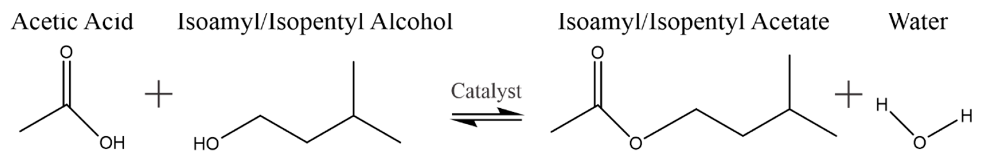
Regarding the production of catalytic isoamyl acetate, one should consider that the acetic acid and isoamyl alcohol conversion, in the presence of an acid catalyst, reacts with the following stoichiometry (Figure 1):
The esterification reaction shown in Equation (1) is, however, limited by chemical equilibrium [7]. While high reactant conversions can be achieved by using either acetic acid or isoamyl alcohol in excess, this approach is an inefficient one, given that it requires large reactor volumes, with extra costs needed to recover unreacted chemical species via product separation from diluted streams. Water separation using conventional distillation from the oxygenate product blend is a complex step, that includes phase separation with multiple azeotropes [8]. As a result, new chemical technologies with enhanced separation performance, such as chromatographic separation and reactive distillation, can be considered [9]. These approaches reduce environmental impact, improved safety, better product quality, and reduced energy consumption.
Esterification intensification can be achieved with the help of reactive distillation (RD) or pervaporation membrane reactors (PVMRs) [10]. RD requires, however, a large difference of volatilities between the reactants and products. This can cause RD performance issues and may require extra energy consumption. On the other hand, for quaternary chemical species blends with azeotropes, such as the one under consideration, PVMRs, with water withdrawal [11], offer special features for enhanced isoamyl acetate production [12,13,14]. However, high purity isoamyl acetate (v.g., >99% ester) will require an additional purification step (v.g., via conventional distillation) [15].
Regarding pervaporation aided esterification, the following has been previously reported: (a) the esterification of acetic acid with ethanol, using PVA/ceramic composite membranes [16], (b) the esterification of acetic acid with isopropanol, using a Pervap® 2201 membrane and a Amberlite-15 resin as a catalyst [17,18], (c) the production of a methyl laurate ester using a catalyst coated polymer membrane [19], and (d) acetic acid esterification with isoamyl alcohol, using a Amberlite IR-120 resin catalyst and a silica membrane [20].
PVMRs can be implemented by using two possible configurations: (i) an ex-situ PVMR, with reaction and separation being performed in two separate stages, or (ii) an in situ PVMR, with the reaction and separation being carried out within a single integrated unit. Given the potential of catalytic reactor-pervaporator membrane configurations, various design alternatives are considered in the present study, via numerical simulation. The approach used here involves experimentally validated thermodynamics, kinetics, and membrane transport models. This allows realistic process simulations, as required for industrial applications. Furthermore, and following the design guidelines set by Lim et al. [21], the PVMR performance is assessed, using key dimensionless parameters, which account for reaction rate/residence time ratio, recycle ratio, reaction rate/pervaporation rate ratio, and membrane selectivity. On this basis, the most favorable configuration, and conditions for maximum water separation and maximum isoamyl acetate yields, are successfully identified.
2. Thermodynamics, Reaction Kinetics, and Membrane Transport Models for PVMR Simulation
2.1. Thermodynamic Model
PVMR models require thermodynamic parameters to describe chemical species transport through the membrane. To accomplish this, liquid phase thermodynamics of acetic acid/isoamyl alcohol/isoamyl acetate/water blends were postulated by Osorio et al. [8] using a Non-Random-Two-Liquid (NRTL) activity coefficient model [22]. Table 1 reports the NRTL parameters (aij, aji, bij, and bji) considered for liquid-liquid and vapor-liquid phase equilibria calculations.
Regarding the NRTL model, the temperature influence on various thermodynamic parameters was accounted for via Equations (1)–(6), as proposed by Osorio et al. [8].
where is the NRTL excess Gibbs energy (J/mol), is the NRTL non-randomness parameter (dimensionless), is the NRTL binary interaction parameter (dimensionless), T is the temperature (K), is the liquid phase molar fraction of component i (mol/mol), and is the activity coefficient of i (dimensionless).
2.2. Reaction Kinetics
Duque et al. [6] and Osorio et al. [23] postulated reaction rate models for both the homogeneous (rhom (mol/(L·h))) and the catalytic (rcat (mol/(gcat·h)) reactions, using an Amberlite IR-120 catalyst. The proposed models are described by Equations (7) and (8), with their respective kinetic constants being given by Equations (9) and (10). Furthermore, and for the equilibrium constant (Keq), a value of 5.0 was calculated, at the 353 K (80 °C) anticipated process operation condition.
where subscripts HAc, ROH, E, and W represent acetic acid, isoamyl alcohol, isoamyl acetate and water, respectively.
In order to consider both the homogeneous and heterogeneous reaction rates, in the context of the non-dimensional PVMR model, it is useful to define a catalyst loading parameter, which relates the mass of the catalyst to the liquid volume of the reactive mixture (i.e., reactor) as follows:
where Wcat is the weight of catalyst used (kg), Vcat is the volume of catalyst used (m3), is the bulk density of the catalyst (mass of catalyst per volume of reactor bed), is the density of solid catalyst (kg/m3), Vreactor is the liquid volume of the reactive mixture (m3), and is the reactor voidage (i.e., volume of void/total reactor volume).
Thus, the overall reaction rate () can be expressed, as a function of an overall dimensionless reaction rate (), as follows:
2.3. Membrane Transport Model
Osorio et al. [24] synthetized, characterized, and evaluated a hydrophilic silica membrane suitable for pervaporation, during the catalytic synthesis of isoamyl acetate, in a previous research study. A corresponding permeation model was developed using pervaporation experimental data and a Maxwell-Stefan approach to mass transfer as per Equation (14):
where is the retentate concentration of the i species (mol/m3), R is the universal gas constant (J/(mol.K)), T is the temperature (K), is the i species chemical potential gradient (J/mol), where the T and P subscripts indicate that this gradient is to be calculated at constant temperature and pressure, xi is the molar fraction of component i, Ni is the permeation flux through the membrane (mol/(m2.h)), is the effective molecular diffusivity (m2/h), is the diffusivity of i in the membrane (m2/h), and is the molar fraction of the stationary membrane material.
Considering that only membrane-component interactions are important in the permeation process and that approaches unity, Equation (14) can be simplified as Equation (15):
Choosing water as a reference component, Equation (15) can be expressed as:
where is the apparent molar diffusion coefficient for water in the membrane (m/h), is the apparent molar diffusion coefficient of component i in the membrane (m/h), and ji is the molar flux of i (mol/(m2.h)).
In addition, the gradient of the chemical potential across the membrane thickness can be expressed as:
where is the liquid phase (retentate) activity of component I, which was calculated by using the aforementioned NRTL model, is the vapor phase (permeate) activity of component i that was calculated using the Hayden-O’Connell model [25], and z is the membrane thickness (m). The substitution of Equations (18) and (20) into Equation (16) leads to:
Furthermore, the diffusion coefficient inside the porous membrane material includes a correction factor for the permeant activity inside the membrane pores (approximated as the activity of the bulk retentate phase), which can be calculated according to the following expressions:
where and Bi are adjustable parameters for each component, as reported in Table 2. This proposed model was validated in the temperature range of 313 to 363 K and at the permeate pressure of 5 mbar.
3. Pervaporation Membrane Reactor Models and Anticipated Unit Configurations
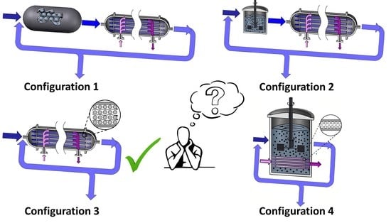
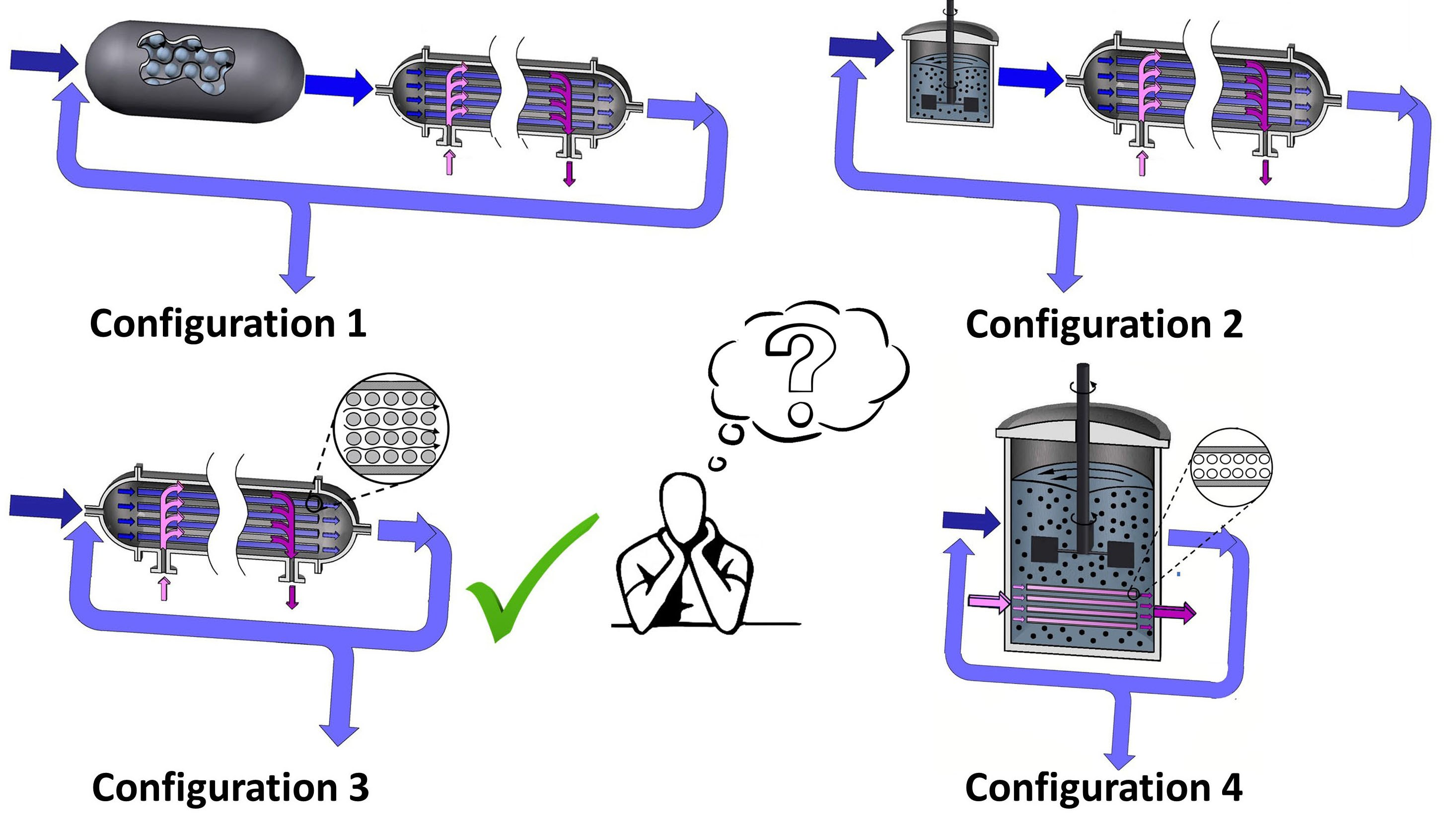
Lim et al. [21] proposed a number of esterification process configurations involving catalytic reactors coupled with pervaporation units. The two basic types of unit arrangements considered involved: (a) A Continuous Stirred Tank Reactor (CSTR) and (b) A Packed Bed Reactor (PBR). Each type of reactor could be engineered with two different modes of operation: (i) an ex-situ separation, in which reaction and separation occurs in two separate units and (ii) an in-situ separation, in which both functions are accomplished in the same process unit.
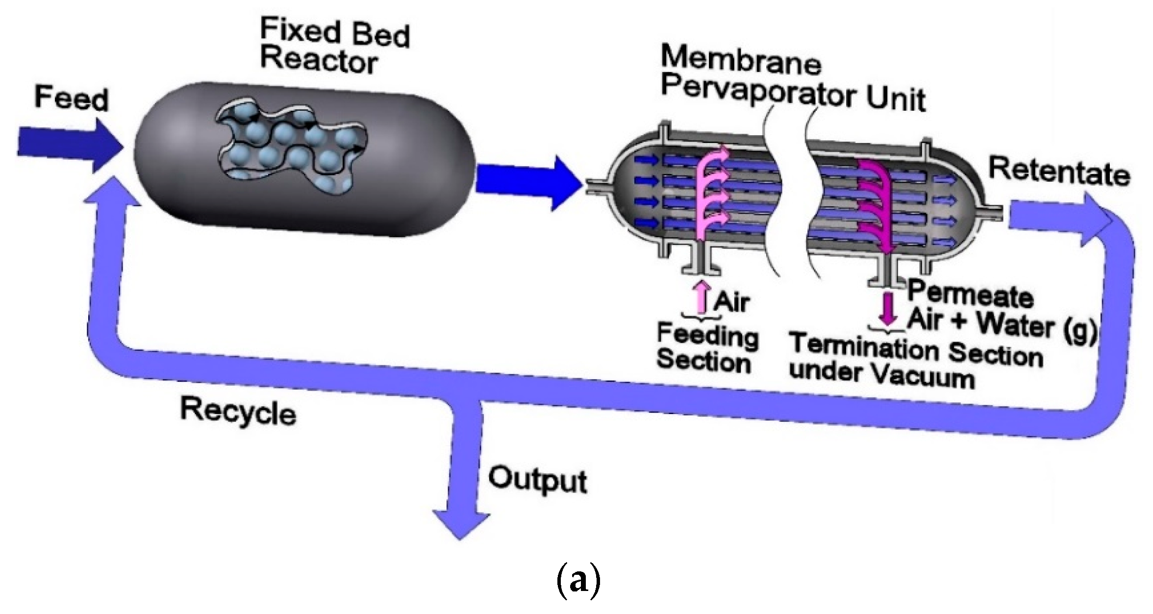
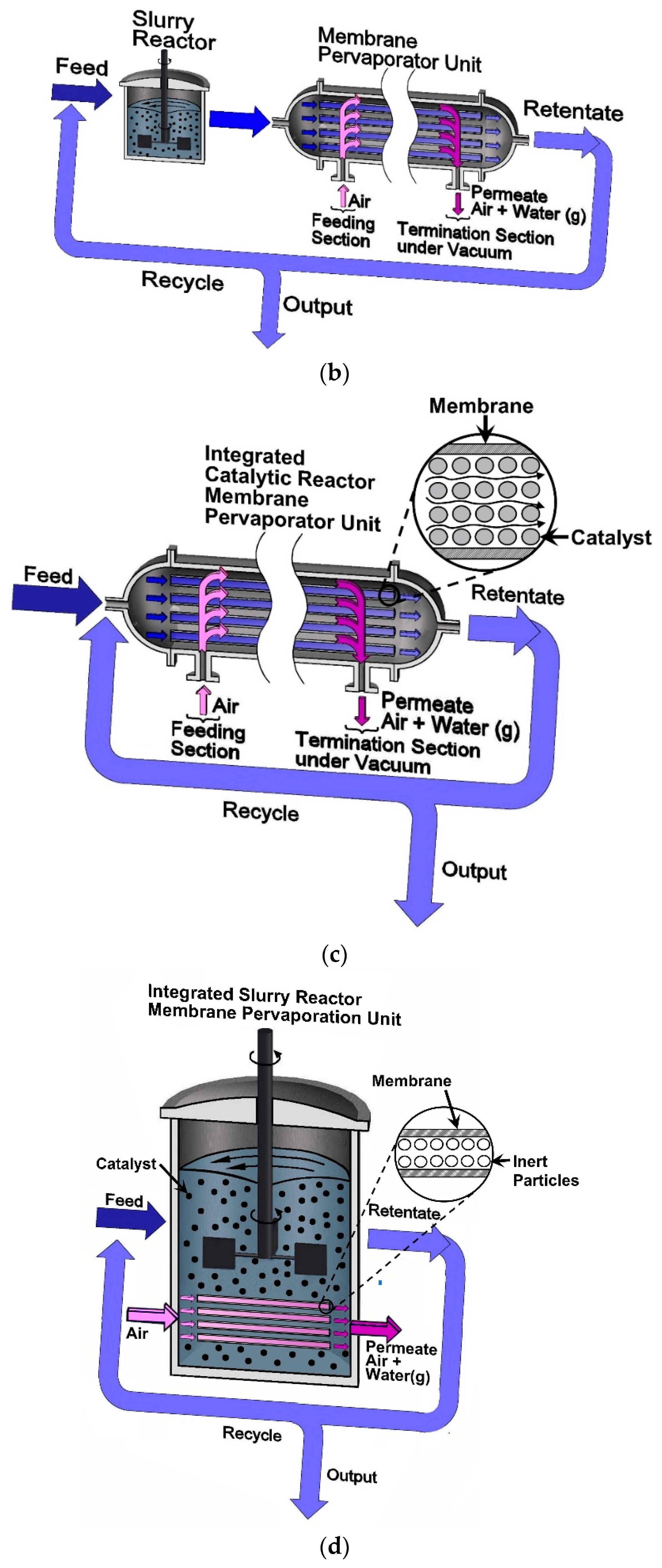
On this basis, four resulting catalytic reactor configurations, with pervaporation membranes, are described in Figure 2 as follows: (Figure 2a) Configuration 1: a FBR+PVMU (Fixed Bed Reactor and Pervaporation Membrane Unit), (Figure 2b) Configuration 2: a SR+PVMU (Slurry Reactor and Pervaporation Membrane Unit), (Figure 2c) Configuration 3: an IFBPVMR (Integrated Fixed Bed and Pervaporation Membrane Reactor), (Figure 2d) Configuration 4: an ISPVMR (Integrated Slurry and Pervaporation Membrane Reactor). Regarding the proposed configurations, a 353 K isothermal operation is considered, given the low heat of the reaction and the best pervaporation yields anticipated [6,23].
Additionally, the following assumptions were adopted for the development of the mathematical models of the four proposed configurations:
- i.
- Steady state operation.
- ii.
- Constant density (liquid phase reaction).
- iii.
- For all four PVMR configurations, the membrane is entirely unreactive (i.e., the reaction ends once the liquid mixture leaves the reaction unit). Transport resistance in the membrane support structure in the permeate side, and concentration polarization effects in the tube-side are considered negligible.
- iv.
- The chemical species evolving in the reactor side in the FB, in both the FBR+PVMU (Configuration 1) and the IFBPVMR (Configuration 3) can be modeled using an ideal plug flow reactor model. This is acceptable given the proper selection of catalyst particle size and fluid dynamic conditions, making concentration changes, a function of the length of the reactor only.
- v.
- The chemical species in the SR, in both the SR+PVMU (Configuration 2) and the ISPVMR (Configuration 4) unit can be simulated by using an ideal perfectly stirred tank reactor, with a uniformly suspended catalyst. This is suitable given the efficient stirring that guarantees that the catalyst density, composition, temperature, and reaction rate are constant throughout the reactor volume.
- vi.
- For all four configurations, the chemical species transport in the pervaporator unit (permeate side) can be assumed to evolve with a plug flow pattern. This is adequate given the carefully selected inert particle sizes and fluid-dynamic conditions that allow species concentration changes to occur, in the unit axial position only. In the particular case of Configurations 1 and 2, this same assumption also applies to the retentate side of the pervaporator, given the loaded inert particles and fluid dynamics.
3.1. Modeling the Fixed Bed Reactor and Pervaporation Membrane Unit (FBR+PVMU) or Configuration 1
For the FBR+PVMU designated as Configuration 1, the molar balance for component i can be written as:
With representing the molar flow rate of species i in the reactor (mol/h), V standing for the independent variable describing the reactor volume (m3) and υi denoting the stoichiometric coefficient for the “i” of chemical species.
One should note that the input flow to the reactor, can be calculated as, the addition of the fresh feed plus the fraction of the species flow recycled from the pervaporation unit effluent, as shown in Equation (25):
with θi being the ratio of the “i” molar flow over the incoming isoamyl alcohol molar flow and R (0 < R < 1) representing the ratio of the i-species recycled back molar flow over the unit exiting reactor-membrane molar flow.
Furthermore, and as described in Figure 2a, the reactor effluent is fed directly to the pervaporator unit, with the differential molar balances of the i component in the retentate membrane side, being given by the following equation:
with A representing the independent variable accounting for the membrane surface area (m2).
In addition, the molar balance in the permeate membrane side (i.e., shell-side), under a co-current flow with respect to the retentate stream, can be simulated by using the following equation:
Furthermore, given the initial conditions for Equations (25) and (26), it is considered that the reactor output flow becomes the pervaporator input flow, as shown in Configuration 1, as follows:
Equations (24)–(27) can be adimensionalized, using the Damköhler number (Da) and the membrane area to the reactor volume ratio (Ω), by taking advantage of the following dimensionless variables and parameters:
where Am is the total membrane surface area (m2), ξ is the dimensionless reactor volume, ζ is the dimensionless membrane area, and Yir, Yim, and Yip are the dimensionless species molar flows in the reactor, in the membrane tube-side, and in membrane shell-side, respectively.
Thus, the set of modeling equations for the FBR+PVMU, in terms of dimensionless variables, is as follows:
3.2. Modeling the Slurry Reactor and the Pervaporation Membrane Unit (SR+PVMU) or Configuration 2
In the case of Configuration 2, Figure 2b, the molar balance for component i in the slurry reactor can be represented by an algebraic equation as follows:
or alternatively the above dimensionless variables and parameters from Equations (30)–(35) can be substituted into Equation (39), as follows:
Furthermore, and for the case of Configuration 2, the same mathematical model from Configuration 1 applies to the pervaporate unit. Thus, Equations (37) and (38) developed for Configuration 1 can be also used in the simulations.
3.3. Modeling an Integrated Fixed Bed and Pervaporation Membrane Reactor (IFBPVMR) or Configuration 3
In the case of Configuration 3 described in Figure 2c, both the chemical reaction and the pervaporation occur simultaneously, in the retentate phase side of the unit. Given that plug flow assumptions can be adopted here, as discussed earlier, the following differential equations can be considered to calculate the IFBPVMR unit performance as a function of the reactor volume, V:
By employing dimensionless variables and parameters, given by Equations (30)–(35), Equation (41) can be modified as follows:
Additionally, when considering a plug flow pattern, in the permeate side of the unit, a non-dimensional molar balance leads to the following expression:
Thus, Equations (42) and (43) can be used for the simulation of the IFBPVMR, designated as Configuration 3.
3.4. Modeling an Integrated Slurry and Pervaporation Membrane Reactor (ISPVMR) or Configuration 4
Configuration 4 can be modeled assuming complete mixing of chemical species in a catalyst suspended slurry. In this case, the pervaporation membrane is engineered as a membrane module, placed inside a reactor unit (Figure 2d). Given that the concentration and temperature are constant throughout the reactor, a retentate material balance for component i can be established as follows:
One should note that the term in Equation (44) represents the difference of the i molar flow output minus the i molar flow fed as a sweep fluid, both in the permeate side. This difference is the equivalent to the amount of i, removed through the pervaporation membrane.
In order to compute the difference, an additional i component balance can be considered by assuming a plug flow pattern in the permeate side of the unit as follows:
where the flux is considered as a variable independent of the membrane area.
Strictly speaking, membrane fluxes depend on both the retentate side and permeate side species concentrations. However, if the retentate side flow is high enough, the retentate composition can be considered to be constant, over the well mixed tank immersed membrane. By substituting Equation (46) into Equation (44), while using non-dimensional variables (Equations (30)–(35)), the following equation is obtained:
Thus, Equations (43) and (47) can be employed for the numerical simulation of Configuration 4.
4. Dimensionless Numbers and Design Variables
Since pervaporation membranes are, in practice, not perfectly selective to water, small amounts of other substances can diffuse to the permeate membrane side, leading to chemical species “leaking”. In order to account for chemical species “leaking”, modification of simulation equations is needed to calculate: (a) the limiting reactant conversion in the reactors [26], and (b) the product yield, which accounts for the amount of ester produced that is obtained in the retentate.
On this basis, the overall conversion (X) and the ester yield (RE)), including the “leaking”, can be computed by employing Equations (48) and (49), respectively:
with being the molar flow of isoamyl alcohol fed to the reactor, representing the molar flow of isoamyl alcohol leaving the unit unreacted, () representing the leaked isoamyl alcohol molar flow in the membrane unit, and () denoting the ester molar flow produced in the reactor.
Furthermore, and for every one of the configurations considered in the present study, it is valuable to define the ranges of expected dimensionless numbers. Given that the reaction rate constants and membrane permeability are set parameters, at a 353 K, their values can be substituted into the equations that define the respective dimensionless numbers (Equations (30)–(35)). With this information, catalyst mass, reactor volume, and membrane area design parameters can be calculated.
Table 3 reports the various relationships between the design variables and the dimensionless numbers, as well as their expected ranges in the isoamyl acetate synthesis, based on our experimental data [20,23,24], or the data from others [27,28,29,30]. One should note that αm = Am/VR is a key design parameter required to determine the reactor geometry and to establish if an in-situ configuration is viable. This is the case given that only a limited range of αm values can be obtained for a specific type of configuration, in which both reaction and membrane separation are occurring simultaneously. Another parameter of interest is DW = DaΩ. DW is not independent of the other design parameters, since it directly assesses the membrane area available for a given feed flow. In fact, the higher the DW value, the higher the water removal capacity for a specific configuration. In addition, and in this context, Da is a parameter representing a dimensionless reactor size, with the membrane cost in an ex-situ configuration being directly related to DW values.
5. Results and Discussion
The membrane pervaporation reactor models were solved using the software MatLab®. Simulations were developed at 353 K isothermal conditions, using a θHAc = 1 stoichiometric feed ratio and the membrane data reported in Table 3. In these simulations, and for units where Ω = 0, or for units without pervaporation membranes, the following can be assumed: (1) the isoamyl alcohol reaction equilibrium conversion is 69%, (2) Da,95%PBR Damköhler numbers of 0.316 and 3.49 are obtained at a 95% isoamyl alcohol equilibrium conversion when R = 0, for PBR and CSTR units, respectively.
5.1. FBR+PVMU (Configuration 1)
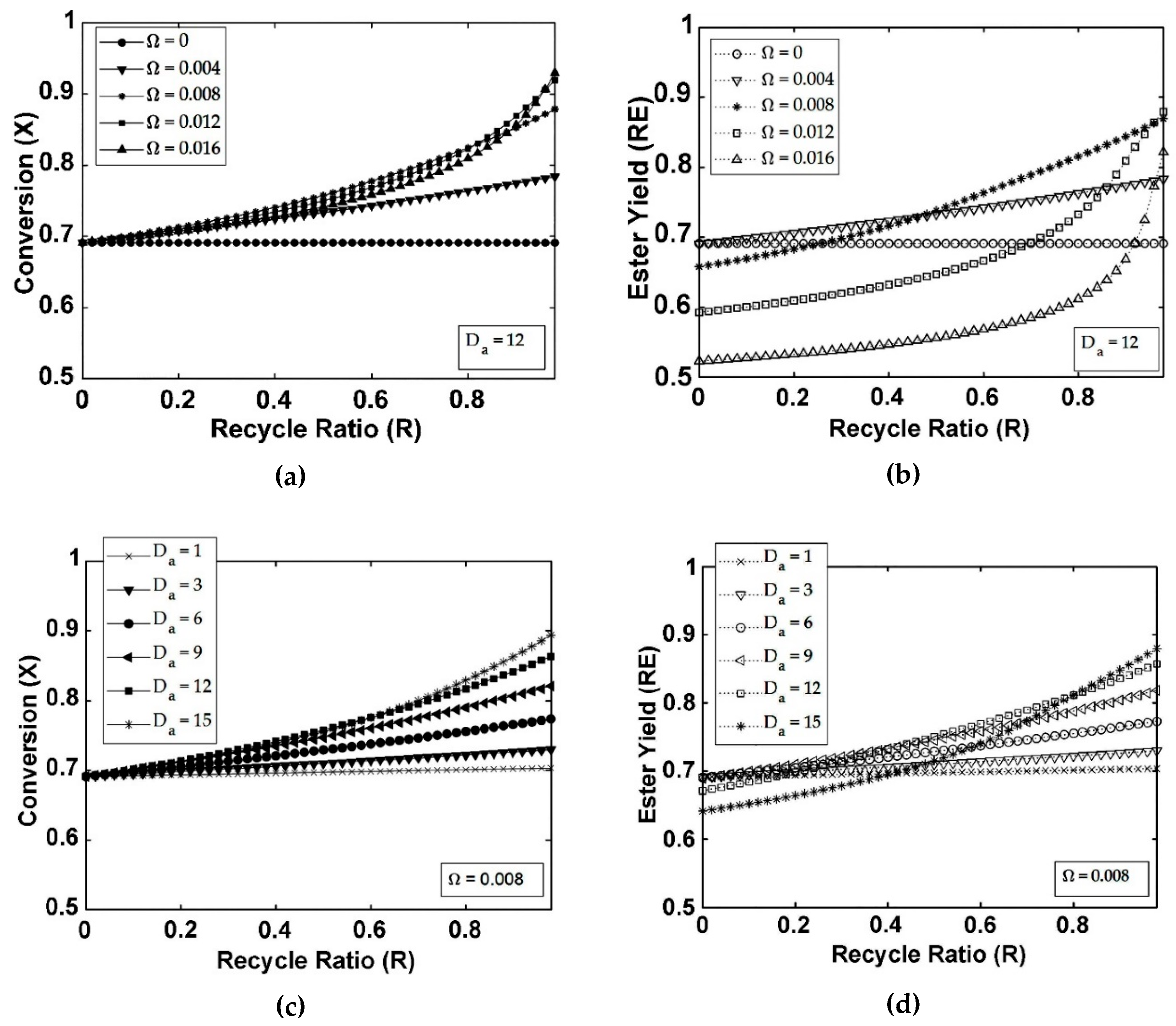
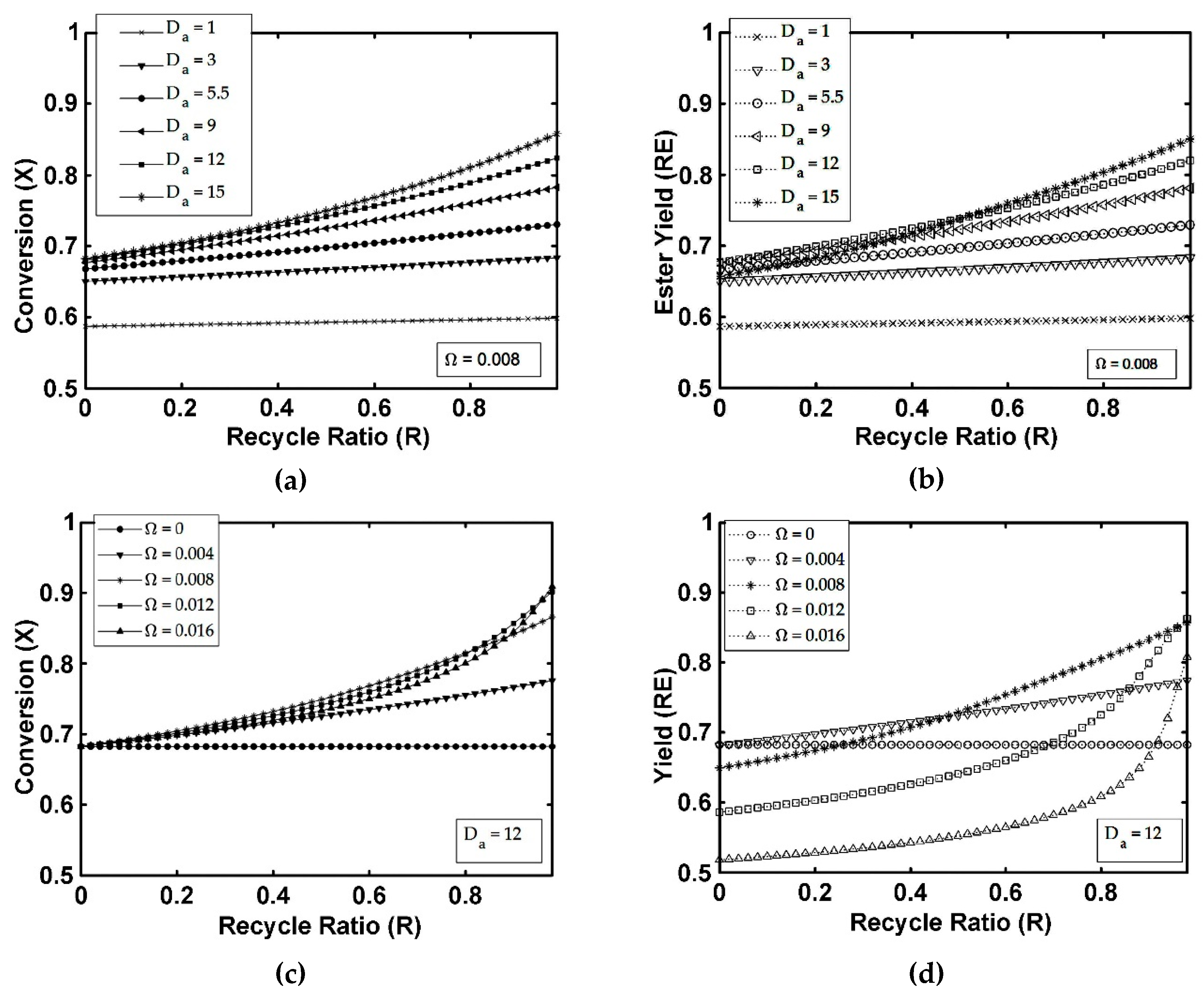
Figure 3a–d report both the isoamyl alcohol conversion and ester yield in an FBR+PVMU (Configuration 1), as a function of the retentate R recycle ratio, the Ω membrane area to reactor volume ratio, and the Da Damköhler number. As shown in Figure 3a,c, having a large Damköhler number (e.g., Da = 12) and R = 0, yields a 69% isoamyl alcohol conversion in an FBR, for all the Ω values considered. On the other hand, one can notice that high R values lead to overall isoamyl alcohol conversions and ester yields, close to the ones obtained in a well-mixed stirred tank reactor. This is also the case when high Ω parameters are considered, given that they positively affect reactor performance.
Figure 3a shows that augmenting the R value influences isoamyl alcohol conversion at Ω = 0 slightly negatively, given that reaction rates modestly decrease as the R increases. This is consistent with the case that uses a recycled feed, rich in isoamyl alcohol and acetic acid reactants, and isoamyl acetate and water products.
In addition, Figure 3a also reports that the feed conversion is a function of the DW parameter, included in the Ω parameter. Thus, as a result, larger DW values improve the isoamyl alcohol conversion via water removal. This is especially the case when the FBR reactor operates at near isoamyl alcohol equilibrium conversion conditions. One should note, however, that this reported effect, can also adversely influence the isoamyl alcohol conversion due to the loss of permeate components. For instance, if the Ω parameter is set to 0.004 or alternatively to 0.008, which correspond to small DW values, a Da larger than the Da,95%PBR (Da in a PBR for 95% conversion) can be obtained. At these conditions, the isoamyl alcohol conversion increases progressively with the R recycle ratio. On the other hand, at intermediate Dw values, the isoamyl alcohol conversion and ester yield display maximum values (not shown here), with these maximum values consistently being obtained at the highest R values. These maximum isoamyl alcohol conversions and ester yields cannot be obtained, however, for very large Dw, given that the isoamyl alcohol conversions and the ester yields increase monotonically with the R parameter.
As a result, from the above observations, design criteria for the FBR+PVMU (Configuration (1) can be drawn as follows: (a) the selected recycle ratio (R) must be less than or equal to an R* value yielding the maximum ester yield, (b) at high values of Dw, the R* becomes 1 and no R optimization process is needed.
Furthermore, quantification of ester losses through the membrane can be obtained by comparing the isoamyl alcohol conversions to the ester yields shown in Figure 3a–d. At R = 0, the isoamyl alcohol conversion is independent of the membrane area, achieving no benefit from the use of a pervaporator unit. The ester yield decreases slightly, however, with an increasing Ω, due to the greater losses of products, in the permeate unit side. In this respect, it is noticed that ester losses rise as the Dw augments. The loss of reagents also increases significantly when the R recycle ratio increases. This explains why the different lines in the graphs of Figure 3a,c representing isoamyl alcohol conversion, for two consecutive values of Ω, intersect each other. Although not shown in Figure 3a–d, these lines do not cross each other when the reactant permeability is zero. One should notice that increasing the Da tends to counterbalance the negative influence of the recycle ratio, with high Da values, leading to isoamyl alcohol conversions exceeding the reaction equilibrium conversion values.
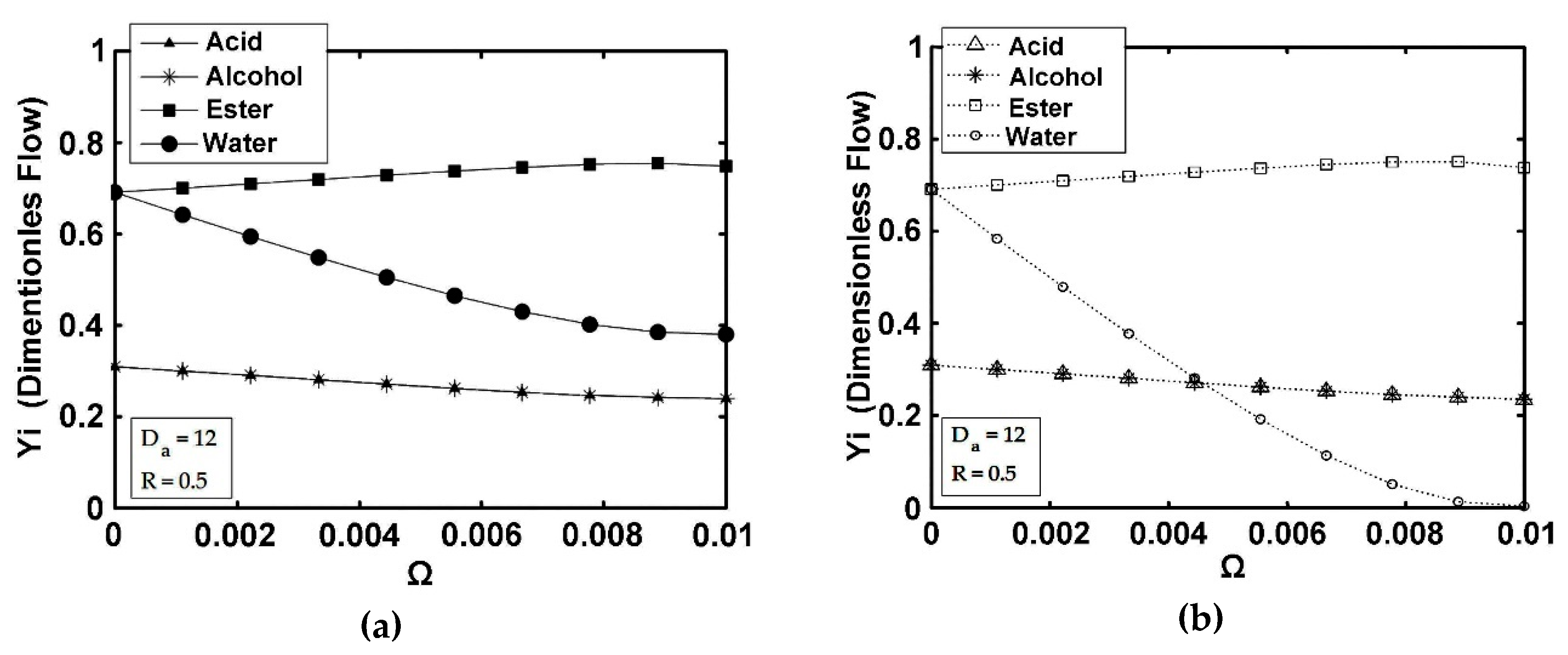
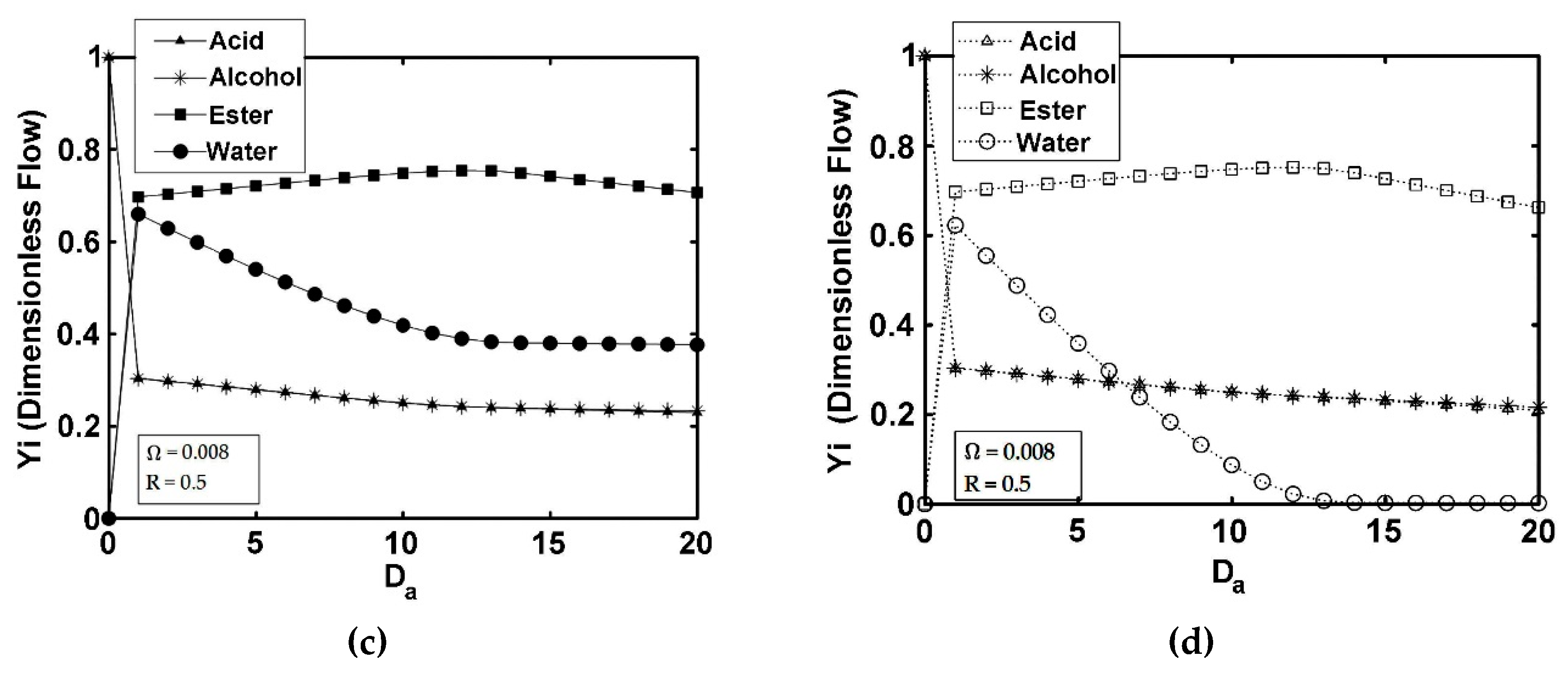
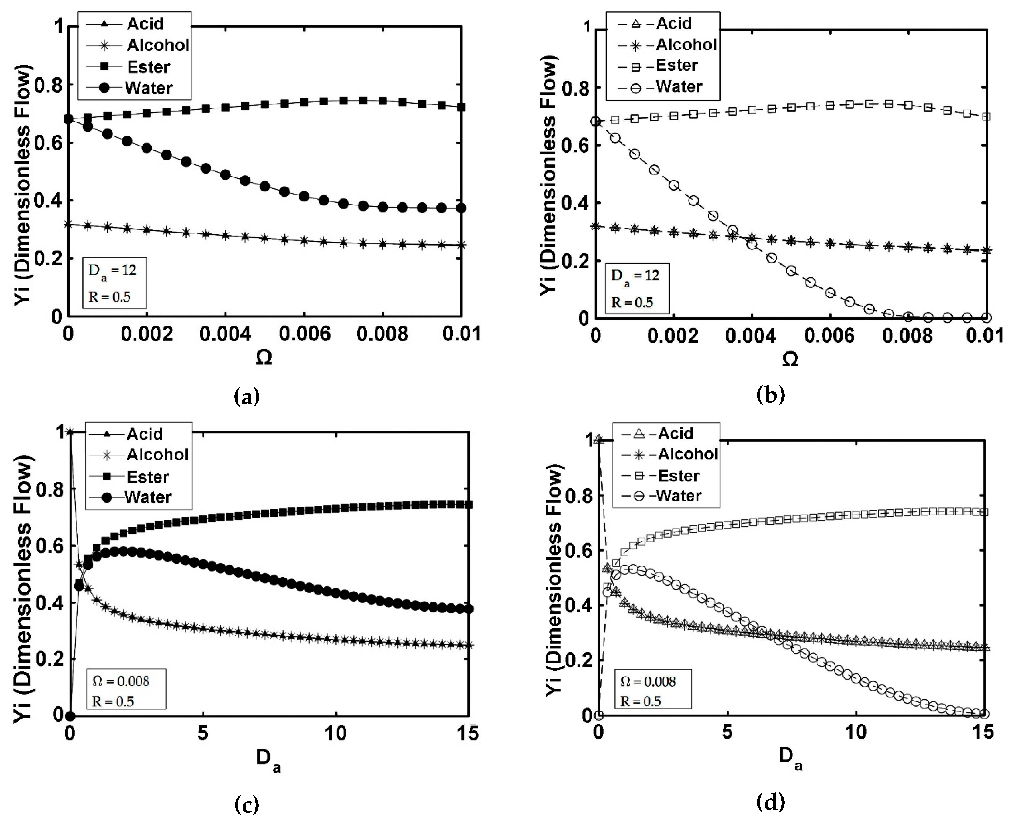
Figure 4 reports the dimensionless flow profiles in the FBR+PVMU (Configuration 1), as a function of Ω (Figure 4a,b) and Da (Figure 4c,d) parameters, at a 0.5 recycle ratio. One can observe in Figure 4a–d, that in an FBR+PVMU, configuration reactant and ester flows are similar to those in a conventional FBR, although the isoamyl alcohol conversion is higher. These reactant flows approach asymptotic values, with increasing Ω and Da, given that product recirculation prevents one from obtaining a complete isoamyl alcohol conversion, regardless of reactor size. One should note as well that while in an FBR, at the reactor outlet, the chemical species are very close to reaction equilibrium (Ω = 0). However, for Ω values larger than zero, the FBR+PVMU configuration can be obtained better than equilibrium values.
Figure 4c also shows a maximum water flow at the retentate outlet, when the Damköhler number increases. This is the result of two opposite effects: (a) isoamyl alcohol is converted in the reactor and therefore water production rises, (b) the membrane area augments and thus, the water removal capacity increases. Due to the occurrence of this maximum water outflow, there are two possible ways to obtain a low water concentration, in the retentate unit side: (1) by operating the retentate unit side at low Da values, to ensure that isoamyl alcohol conversion remain low, (2) by operating the retentate unit side at high Da values to ensure that isoamyl alcohol conversion and water removal remain high (Figure 4d). To increase ester production, however, the second option is the desirable one. This provides a design criterion for any type of membrane reactor: to choose a Da > Da*, with Da* being the value at which the water concentration reaches a maximum level.
5.2. SR+PVMU (Configuration 2)
Isoamyl alcohol conversions and ester yields in a conventional CSTR are independent of the recycle ratio, as shown in Figure 5c,d, for Ω = 0. However, for the SR+PVMU (Configuration 2) equipped with membrane pervaporation, the higher the R recycle values, the higher the isoamyl alcohol conversion, with no isoamyl alcohol conversion maximum observed, in the range of conditions studied.
Furthermore, regarding the dimensionless flows in the SR+PVMU reported in Figure 6, similar considerations apply as those reported for the FBR+PVMU. The difference here, however, is that the ester yield flow for the SR+PVMU stabilizes at a lower level, than that in the FBR+PVMU.
In this respect, if one compares the results obtained in the SR+PVMU (Configuration 2) versus those obtained in the FBR+PVMU (Configuration 1), the following can be observed: (a) for the same dimensionless parameters, the isoamyl alcohol conversion in a FBR+PVMU is always greater than in a SR+PVMU, (b) when R approaches 1, both configurations produce the same isoamyl alcohol conversion but different ester yields, (c) for an increasing R, the isoamyl alcohol conversion in a SR+PVMU and a FBR+PVMU, both depend on Ω and Da, and (d) for intermediate R values, reactant losses lead to a maximum isoamyl alcohol conversion.
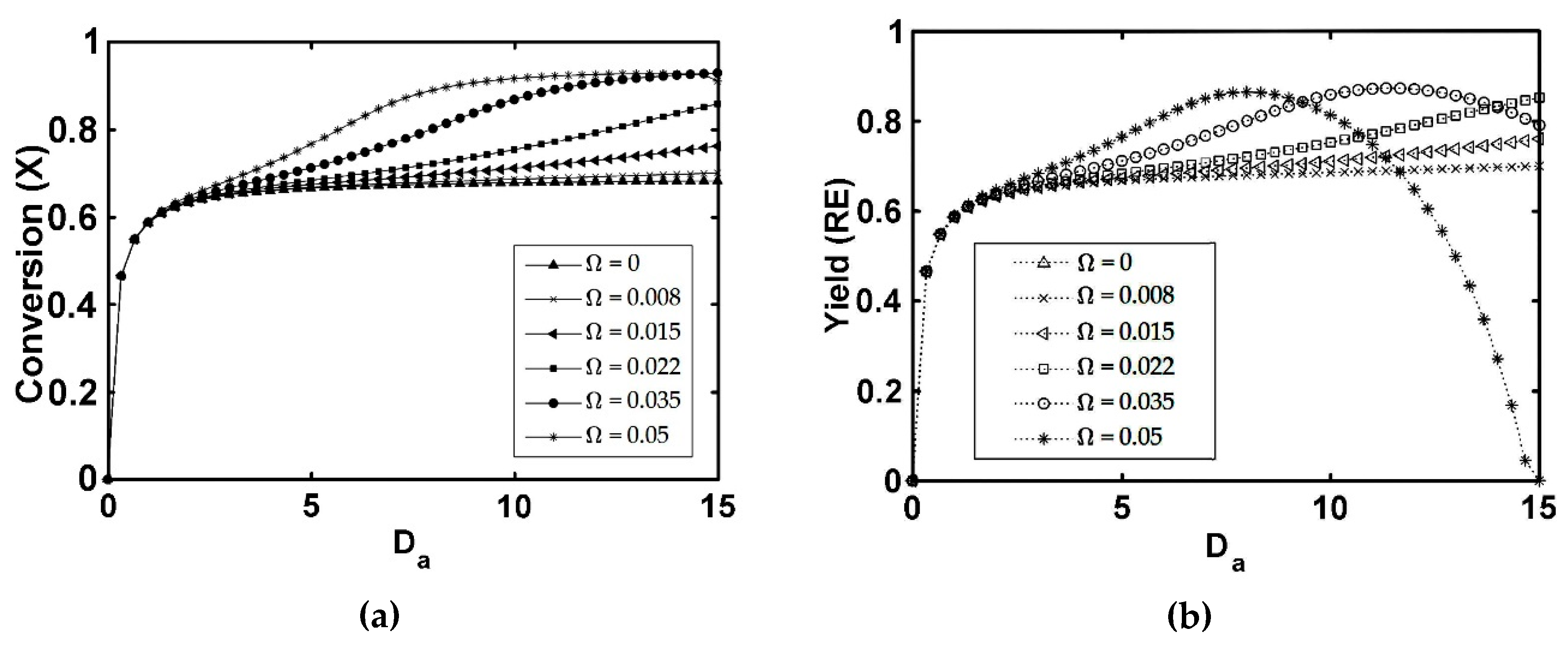
5.3. IFBPVMR (Configuration 3)
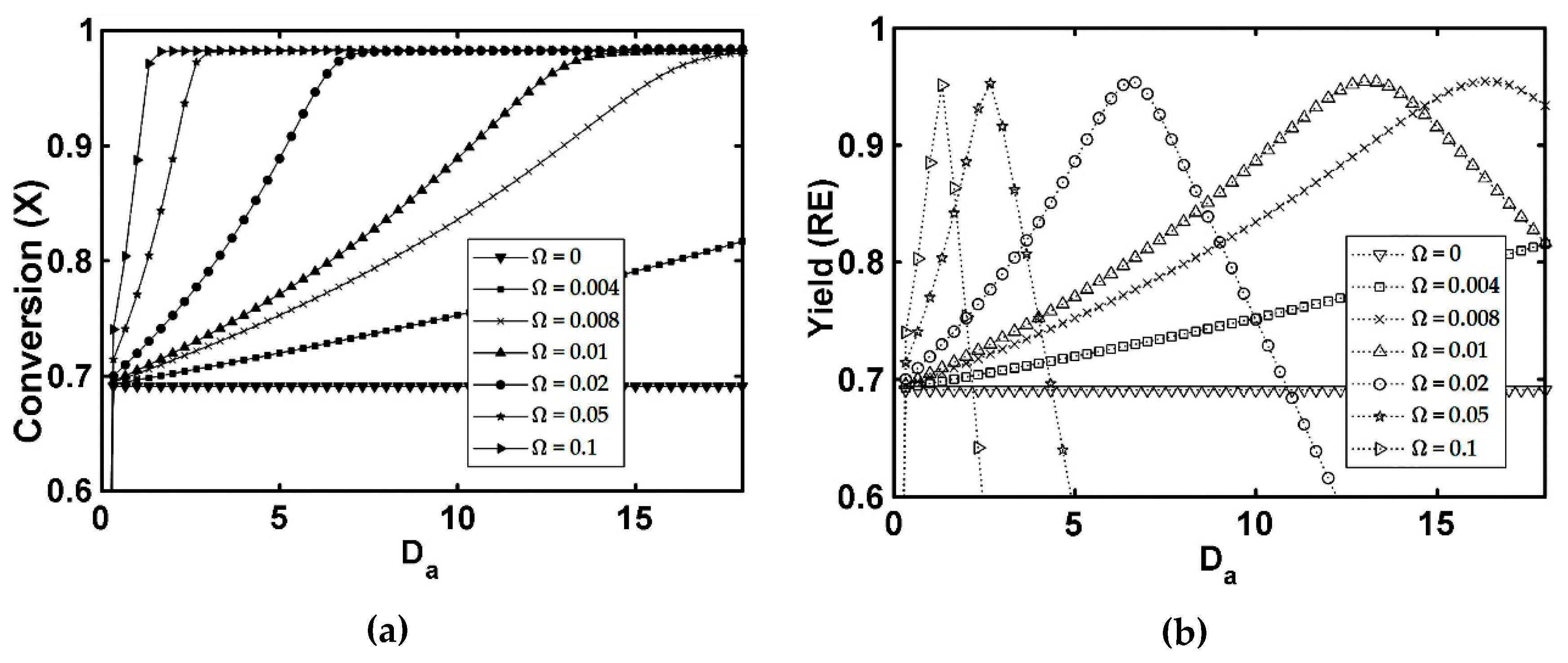
When evaluating the performance of integrated reactors, such as that of Configuration 3, one can observe a significant difference when compared to the performance of coupled units, such as that of Configurations 1 and 2. Integrated units allow one to remove the unwanted species as soon as they are formed. As result, with integrated reactors, it is possible to achieve significantly higher conversions than in coupled units. Performance in integrated units, however, is limited by the reagents’ leakage to the permeate membrane side. Given that permeate species recirculation promotes leaking, permeate recycle in the IFBPVMR is considered unsuitable. In this case, the Da and Ω parameters must be carefully selected via a parametric sensitivity analysis, in order to obtain high isoamyl alcohol conversions and ester yields.
Figure 7a describes how the isoamyl alcohol conversion increases with an enlargement of both the reactor size (given by Da) and the specific membrane area (given by Ω). The isoamyl alcohol conversion reaches values close to 0.98, for Ω values larger than 0.004, when the selected Da surpasses a minimum Da value. On the other hand, for Ω values lower than 0.004, the isoamyl alcohol conversions significantly decrease at all Da values, due to the greater losses of ester. Furthermore, when the IFBPVMR (Configuration 3) and the FBR+PVMU (Configuration 1. R = 0.5) performances are compared, one can observe that in the IFBPVMR case, the isoamyl alcohol conversion is enhanced (e.g., for the same Ω = 0.008 and Da = 12 values). This is a result of the yield ester losses reduction that occurs in the IFBPVMR, as shown in Figure 3 and Figure 7.
Figure 7b reports ester yields at various Da and Ω values, allowing one to establish the following design criterion for the IFBPVMR(Configuration 3): the Ω value should exceed Ω* = 0.004, with Ω* being the lowest value at which a maximum ester yield is achieved for a set Da.
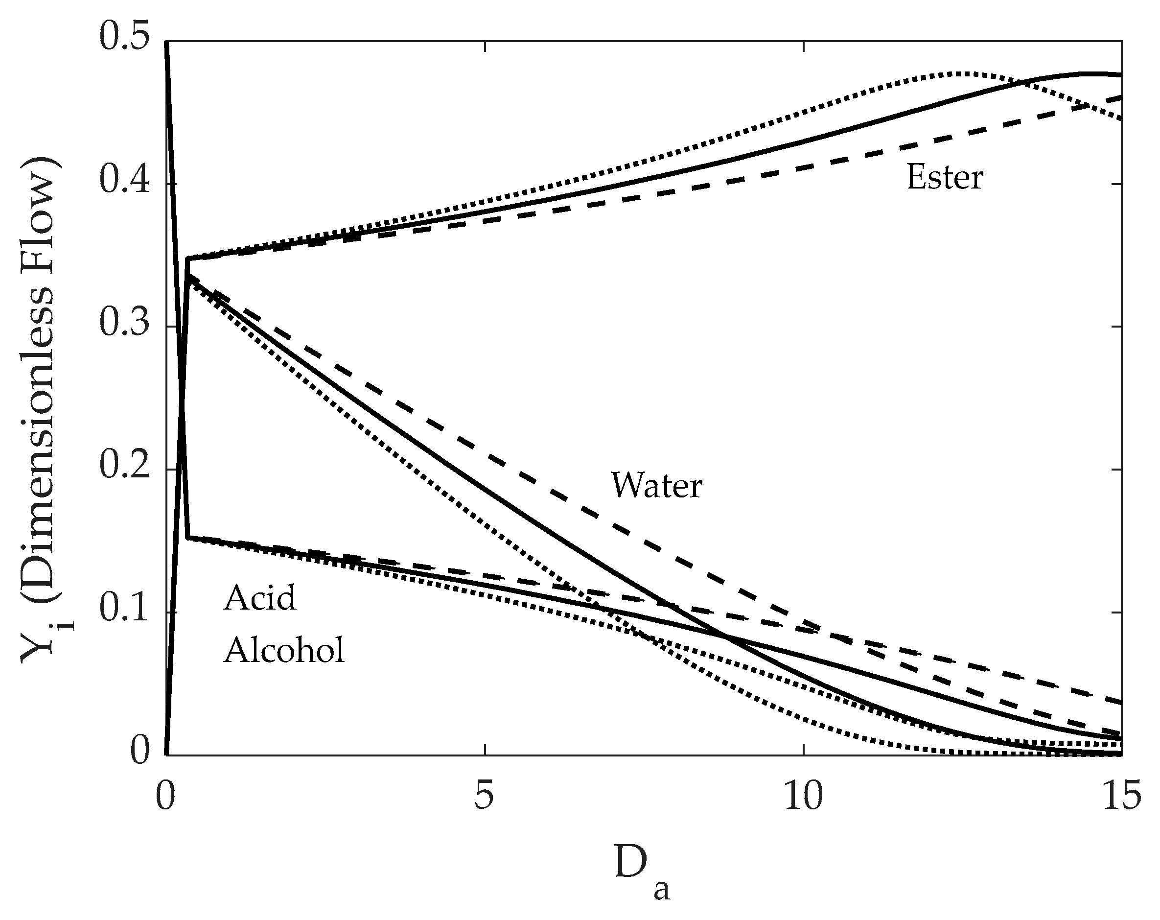
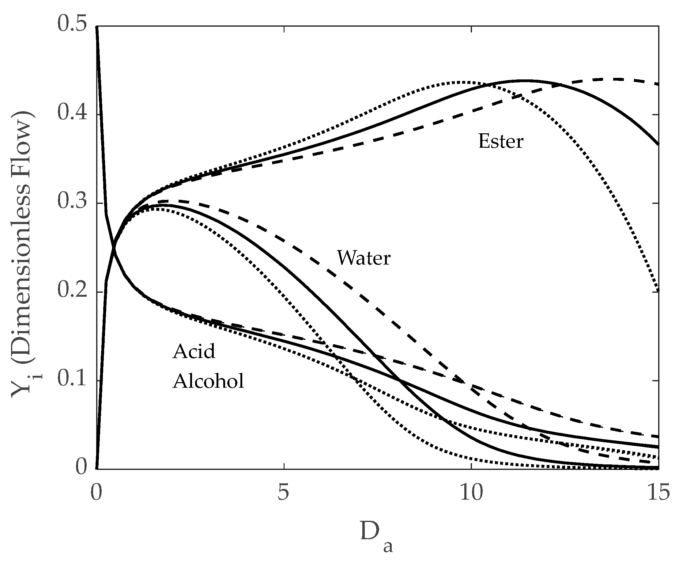
Figure 8 reports species dimensionless flows (Yi) as a function of the Da reactor parameter, for three specifics Ω membrane areas. It can be observed that there is a common maximum water flow, with the decreasing as the Da and Ω membrane area increase. Given that an ideal esterification membrane reactor should produce pure ester in the retentate stream, it can be concluded (by comparing the output flows in Figure 4 and Figure 8), that the IFBPVMR (Configuration 3) can provide a close to ideal esterification. For example, with a Ω = 0.008 and a Da = 12, the ester yield stands at 95.3% and a conversion of 96.5% is reached, with the product having a 95% (molar) or 97% (mass) ester purity.
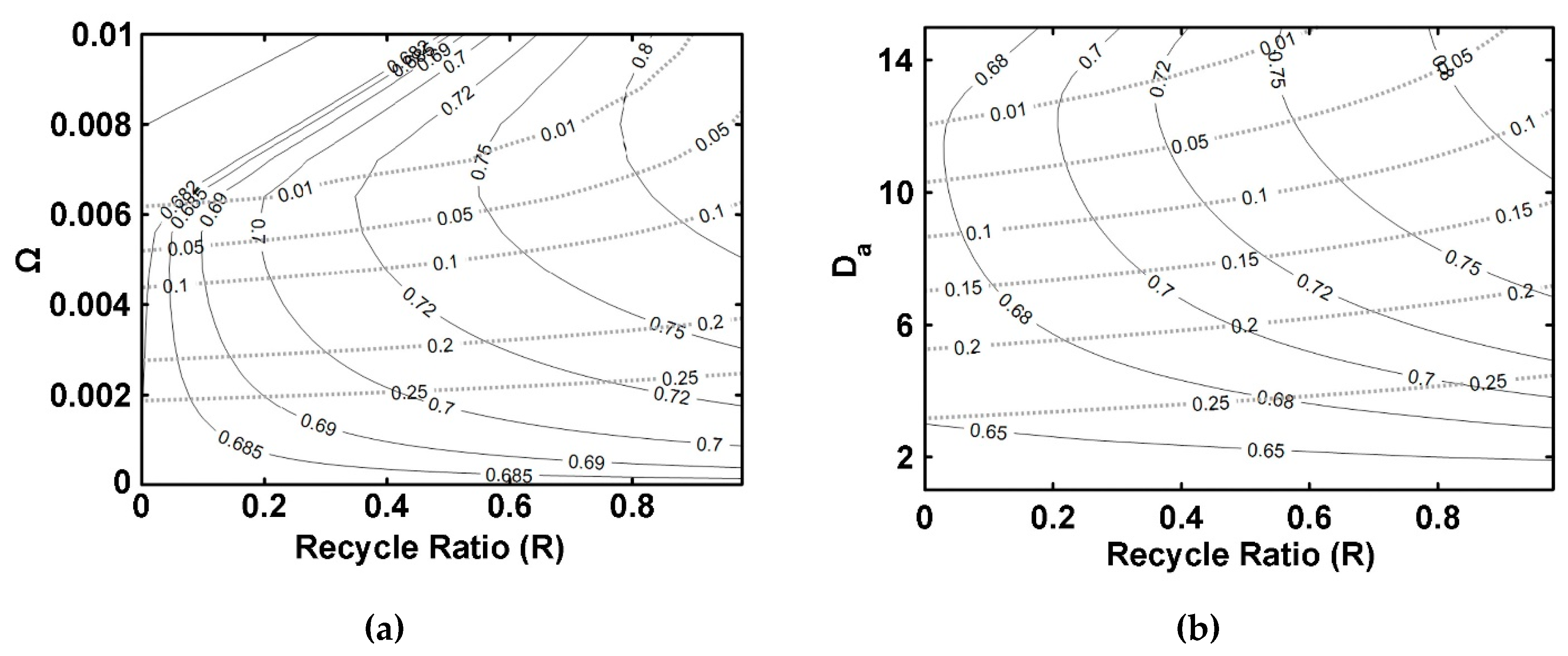
5.4. ISPVMR (Configuration 4)
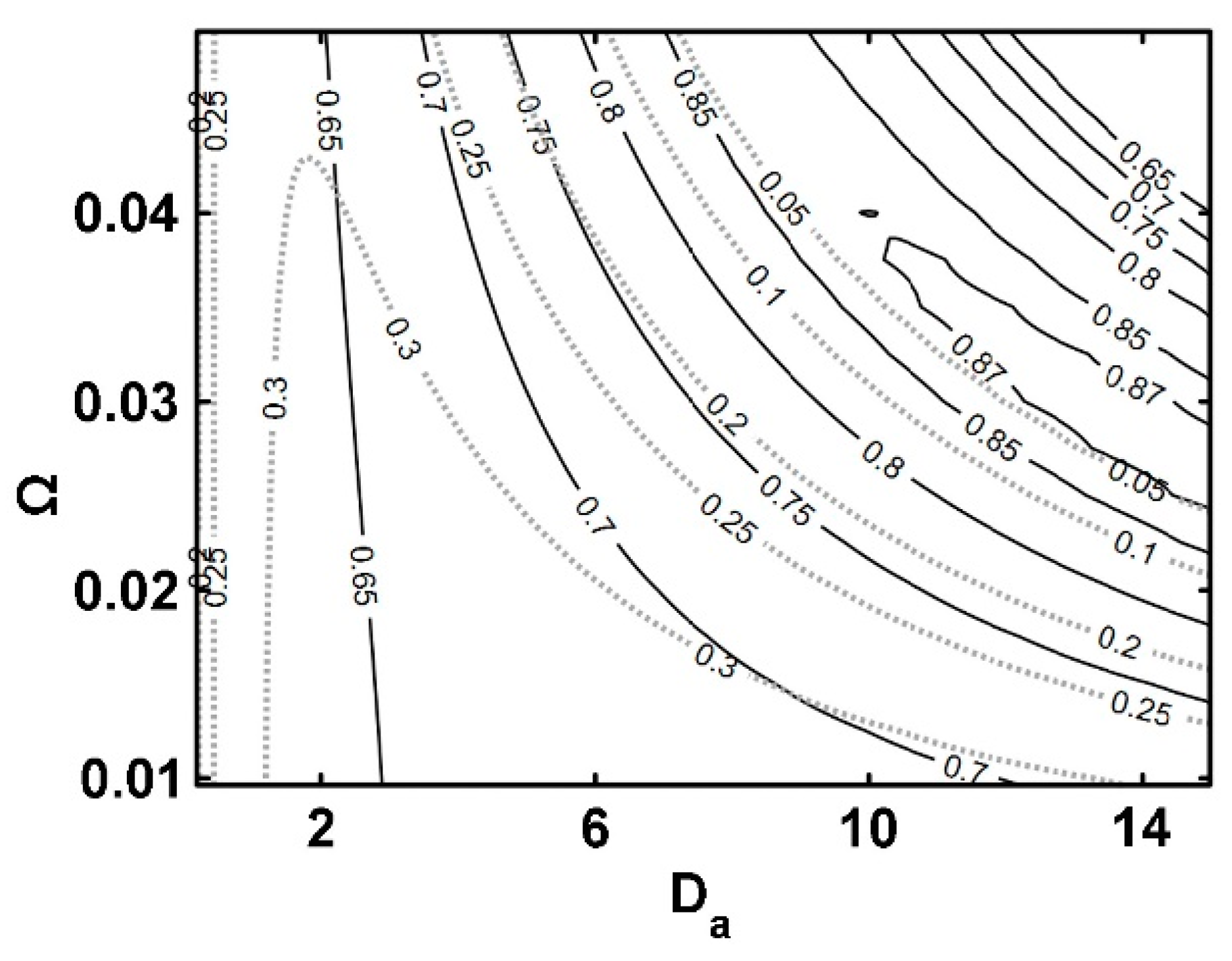
The ISPVMR (Configuration 4) offers an alternate integrated arrangement. As shown in Figure 9a,b, the ISPVMR displays similar isoamyl alcohol conversions and ester yields trends as the IFBPVMR (Configuration 3) as follows: (a) Minimum Ω and Da values are required to reach the highest isoamyl alcohol conversions, (b) Optimum ester yields are obtained for specific sets of Ω and Da parameter values. However, when comparing Figure 7 and Figure 9, in the ISPVMR, at similar operation conditions, the isoamyl alcohol conversion is always lower than that obtained in the IFBPVMR.
Figure 10 also displays Yi dimensionless flows with similar trends, for the ISPVMR (Configuration 4) and the IFBPVMR (Configuration 3). One can notice, however, that the ester recovered in the retentate membrane side of the ISPVMR has a lower purity than the one obtained in the IFBPVMR, at similar operating conditions.
Thus, for the ISPVMR (Configuration 4), the isoamyl alcohol conversion increases monotonically, with the Da. At a given Da* value, however, ester yields display a maximum, at a specific Da*. On this basis, the following design guideline can be established: For a specific Ω, select a Da* value that provides high isoamyl alcohol conversions and simultaneously a maximum ester yield.
5.5. Summary of Design Criteria
Based on the simulation results presented in this study, it is possible to establish design criteria (heuristics) for the development of isothermal membrane reactors, required for the liquid-phase esterification of acetic acid with isoamyl alcohol (using a silica membrane and an Amberlite IR-120 ion exchange resin as a catalyst). These design criteria can be summarized as follows:
- The membrane reactor design should have, as a main objective, to enhance ester yield, with less consideration given to the conversion of the limiting reagent.
- The design of a membrane reactor for liquid phase esterification can only be considered suitable if the ester yield surpasses chemical equilibrium values, achieved in conventional reactors (e.g., unit without membrane).
- The specific design selected must ensure that a retentate water concentration is low enough not to require further ester purification by azeotropic distillation.
- The simulations of the different catalytic reactor-pervaporator membrane configurations show that the one which performs best is the integrated IFBPVMR (Configuration 3), which demonstrates that: (a) for a set Da, there is a best Ω*, where the ester yield becomes a maximum, (b) for a set Ω, there is an optimum Da*, at which the ester yield reaches a maximum level, (c) for a set Ω, there is a Da* where the retentate water mole fraction reaches a highest value.
- The simulation of the best performing integrated IFBPVMRs further confirms that for set Ω and Da values in a reactor with recycle, there is an R* at which the ester yields reach maximum levels.
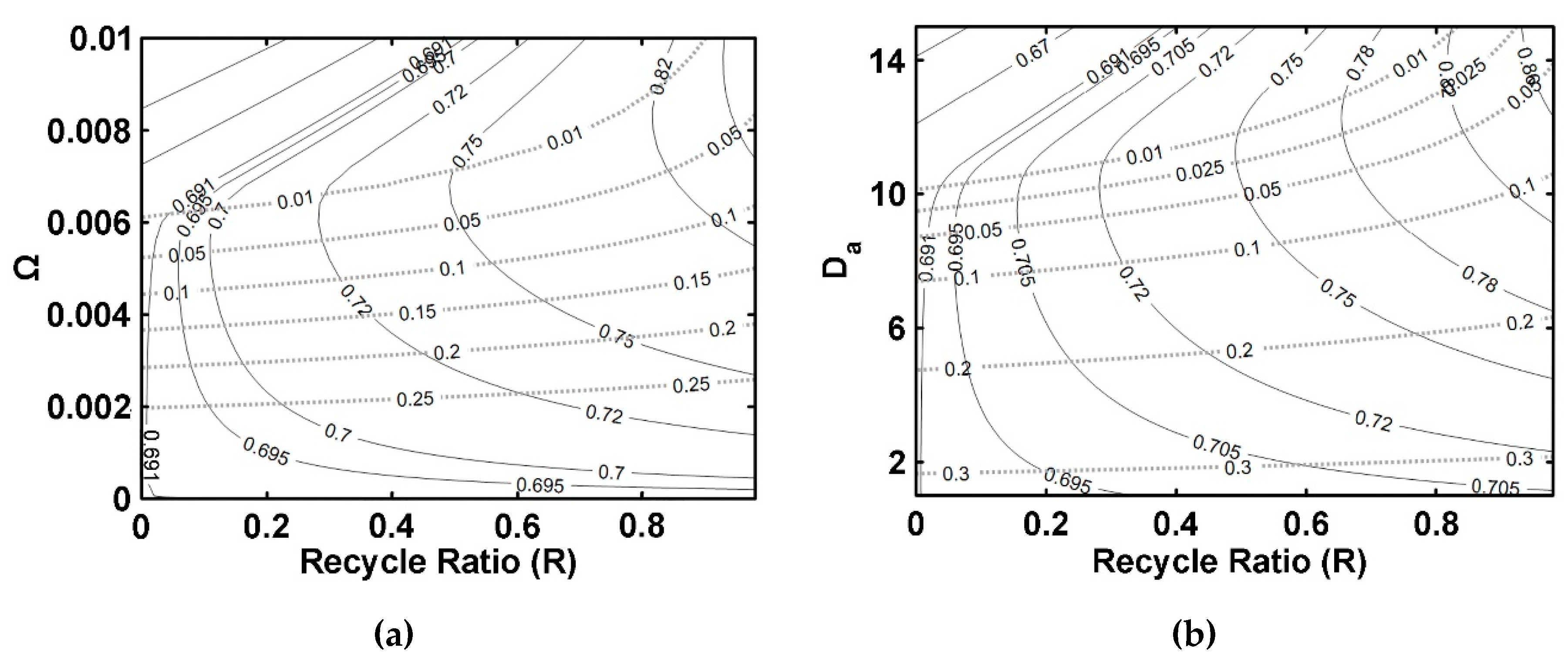
By using these criteria, it is possible to develop charts that provide guidelines to design membrane reactors, such as values of Ω and Da (Figure 11, Figure 12, Figure 13 and Figure 14). They should include contours of constant ester yields (solid lines) and constant retentate water mole fractions (dashed lines), as functions of Ω and Da. By using these charts in conjunction with Table 3, and the proposed criteria developed here, it is possible to design a pervaporation membrane reactor to achieve a given production target, such as a desired ester yield or an isoamyl alcohol conversion. A suggested algorithm to accomplish this task is as follows:
Step 1: Choose the desired output ester yield and the maximum output water fraction required in the retentate.
Step 2: Select the corresponding design chart for a given membrane reactor type, as reported in Figure 11, Figure 12, Figure 13 and Figure 14, with this being either Configuration 1 (FBR+PVMU), Configuration 2 (SR+PVMU), Configuration 3 (IFBPVMR), or Configuration 4 (ISPVMR). If possible, always choose in situ configurations over ex situ configurations, fixed bed flow reactors over perfectly mixed slurry reactors. The IFBPVMR is always a best preferred reactor configuration choice.
Step 3: Locate the desired ester yield line in the appropriate graph and determine the lowest values of Da, Ω, and R (if required) that allow achieving the desired ester yield, in agreement with the criterion of obtaining a maximum water fraction in the retentate.
Step 4: Check if the obtained value of Ω is in the allowed parameter range using Table 3. If the value is too high to be achieved in an in-situ configuration, switch to an ex-situ configuration and repeat the procedure or try a lower value of Ω and a higher Da.
Step 5: Once this iterative process is complete, one can calculate the possible isoamyl alcohol conversion and ester yield.
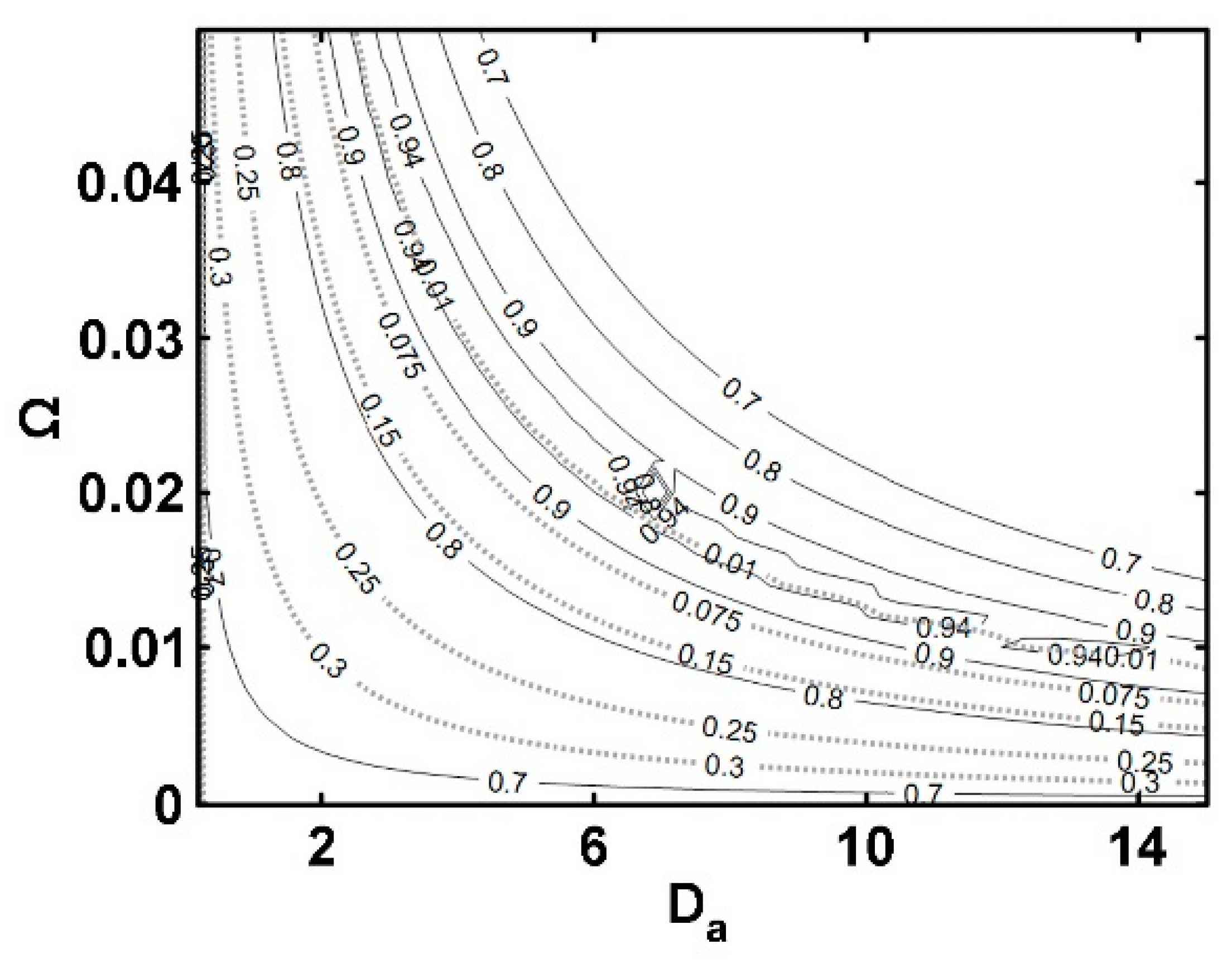
To illustrate the applicability of the proposed method, first refer to the results presented in Figure 13 (for IFBPVMR). Consider the expected design parameter range: 0.31 < Da < 15 and 10−4 < Ω < 5 × 10⁻³, as shown in Table 3. One can see that at such conditions, ester yields and water retentate molar fractions are restricted to 0.7 and 0.3 values, respectively, as shown in Figure 13. These values are considered good pervaporator membrane reactor performance. It should be noted that Figure 13 also provides information about the water permeability required to increase ester yields up to 0.94 maximum values, in the IFBPVMR (Configuration 3), while keeping a constant Da. It is noteworthy to mention that this high yield can be obtained in Configuration 3, via an important increase of the Ω parameter up to 1.5 × 10⁻², which is consistent with the Ωs reported in Table 3 (10−9 < Ω < 0.44 with 0.29 < Da < 15). Thus, the present study establishes desirable and attainable goals, for new IFBPVMR units, where a significant number of internal tubes holding membranes are implemented.
6. Conclusions
In this study, design criteria were developed for four different configurations of isothermal catalytic membrane reactors based on realistic thermodynamic, kinetic, and permeation models, specifically developed for the esterification of acetic acid with isoamyl alcohol, catalyzed by Amberlite IR-120. Computations were considered in the context of these four different process configurations with pervaporation membranes place inside (in situ) and outside (ex situ) the reactor units.
Simulations showed that catalytic membrane reactors, if properly designed, may exceed isoamyl alcohol reaction chemical equilibrium. However, their performance may be affected by reagent leaks to the permeate stream, limiting, in practice, achievable isoamyl alcohol conversions. Thus, it is preferable to base reactor performance on ester yield and retentate water molar fractions.
It is demonstrated in this research, that the Integrated Fixed Bed and Pervaporation Membrane Reactor (IFBPVMR) or Configuration 3 is a preferred option over the continuously integrated mixed slurry pervaporation membrane reactor (ISPVMR), given that it has the potential of delivering 94% high ester yields through innovative membrane designs.
Author Contributions
Conceptualization, M.Á.G.-G. and I.D.-G.; methodology, M.Á.G.-G. and I.D.-G.; software, J.D.Q.-A. and M.Á.G.-G.; validation, M.Á.G.-G., I.D.-G. and J.D.Q.-A.; formal analysis, M.Á.G.-G., I.D.-G., J.D.Q.-A. and H.d.L.; writing—original draft preparation, M.Á.G.-G., I.D.-G. and J.D.Q.-A.; writing—review and editing, M.Á.G.-G., I.D.-G., J.D.Q.-A. and H.d.L.; supervision, M.Á.G.-G. and I.D.-G.; project administration, M.Á.G.-G. and I.D.-G.; funding acquisition, M.Á.G.-G. and I.D.-G. All authors have read and agreed to the published version of the manuscript.
Funding
The authors gratefully acknowledge the financial support of Universidad Nacional de Colombia, Sede Manizales (Convocatoria para el Apoyo a Proyectos de Investigación de la Facultad de Ingeniería y Arquitectura de la Universidad Nacional de Colombia Sede Manizales 2019: Proyecto HERMES: 46213) y Convocatoria para el Apoyo al Desarrollo de Tesis de Posgrado y Trabajo de Grado de Pregrado de la Facultad de Ingeniería y Arquitectura de la Universidad Nacional de Colombia Sede Manizales 2020 (Proyecto HERMES: 50955). Jesús David Quintero was a beneficiary of a COLCIENCIAS grant (Convocatoria 727-2015 Doctorados Nacionales FP44842-133-2017). The authors gratefully acknowledge the financial support of the Natural Sciences and Engineering Research Council of Canada (NSERC).
Data Availability Statement
No new data were created or analyzed in this study. Data sharing is not applicable to this article.
Acknowledgments
We thank Florencia de Lasa for the provided help in editing this document and drafting the graphical abstract and several figures in this paper, as well as Miguel Duque Bernal for fruitful discussions.
Conflicts of Interest
The authors declare no conflict of interest.
Nomenclature
| A | Membrane area (m2) |
| Am | Total membrane area (m2) |
| a | NRTL adjustable parameter (-) in Equation (2). Thermodynamic activity (-) in Equations (19)–(23). |
| B | correction factor for the permeant activity inside the membrane (-) |
| b | NRTL adjustable parameter (K) |
| c | NRTL adjustable parameter (-) |
| ci | Retentate concentration of the i species (mol/m3) |
| D | Diffusion coefficient (m2/h) |
| D′ | Apparent molar diffusion coefficient in the membrane (m/h) |
| Dim | Diffusivity of i in the membrane (m2/h) |
| Da | Damköhler number (-) |
| d | NRTL adjustable parameter (K−1) |
| e | NRTL adjustable parameter (-) |
| F | Molar flow (mol/h) |
| f | NRTL adjustable parameter (K−1) |
| G | NRTL Excess Gibbs Energy (J/mol) |
| ji | Molar flux of I (mol/(m2.h)) |
| Keq | Equilibrium constant (-) |
| k1,hom | Kinetic constant for homogeneous reaction (mol/L.h) |
| k1,cat | Kinetic constant for catalytic reaction (mol/gcat.h) |
| N | Flux of permeation trough membrane (mol/m2.h) |
| P | Pressure (bar) |
| Overall reaction rate (-) | |
| R | Universal gas constant (J/mol*K) in Equations (15) and (18)–(20). Recycle ratio (-) fraction of the molar flow of i species exiting the reactor-membrane-unit, (mol/h), recycled back to reactor entrance, 0 < R < 1). |
| RE | Ester yield (-) |
| r | Reaction rate (mol/Lh for homogeneous or mol/gh for heterogeneous reaction) |
| s | +1 for countercurrent flow and −1 for parallel flow |
| T | Temperature (K) |
| V | Reactor volume (L) |
| Vcat | Volume of catalyst used (m3) |
| VR | Total reactor volume (L) |
| Wcat | weight of catalyst used (kg) |
| X | Overall reactant conversion (-) |
| x | Liquid phase molar fraction (mol/mol) |
| Y | Dimensionless molar flow/Molar flow of “i” species/Total molar flow (-) |
| z | Membrane thickness (m) |
| Greek symbol | |
| α | NRTL Non-randomness parameter (-) |
| αm | membrane area/reactor volume ratio (m2/L) |
| γ | Activity coefficient (-) |
| ε | Packed bed porosity (L/L) |
| θ | Acetic acid/Isoamyl alcohol molar feed ratio (-) |
| μ | Chemical potential (J/mol) |
| ν | Stoichiometric coefficient (mol/mol) |
| ξ | Dimensionless reactor volume coordinate (-) |
| ρbulk,cat | Bulk density of solid catalyst (g/L) |
| ρcat | Density of solid catalyst (g/L) |
| ζ | Dimensionless membrane area coordinate (-) |
| τ | NRTL binary interaction parameter (-) |
| Reactor voidage (volume of void/total reactor volume) | |
| Ω | Dimensionless membrane area/reactor volume ratio (-) |
| Superscripts | |
| e | Effective |
| i | Component |
| in | Input |
| j | Component |
| n | Total number of components |
| ° | Reference state/fresh feed |
| out | Output |
| P | Permeate |
| R | Retentate |
| Subscripts | |
| A | Limiting reactant |
| B | Reagents feed ratio |
| Cat | Catalyst |
| E | Ester |
| HAc | Acetic acid |
| i | Component |
| im | Component i flowing through the membrane section |
| k | Number of components |
| m | membrane |
| ROH | Isoamyl alcohol |
| r | Reactive retentate |
| p | Permeate |
| W | Water |
| Abbreviations | |
| HOC | Hayden-O’Connell |
| CSTR | Continuous Stirred Tank Reactor |
| FBR+PVMU | Fixed Bed Reactor and Pervaporation Membrane Unit |
| SR+PVMU | Slurry Reactor and Pervaporation Membrane Unit |
| IFBPVMR | Integrated Plug Flow Pervaporation Membrane Reactor |
| ISPVMR | Integrated Slurry and Pervaporation Membrane Reactor |
| NRTL | Non-Random Two Liquid |
| PFR | Plug Flow Reactor |
| PFPVMR | Plug Flow Pervaporation Membrane Reactor |
| PVMRs | Pervaporation membrane reactors |
References
- IEA. Renewables 2021; International Energy Agency: Paris, France, 2022. [Google Scholar]
- Encyclopedia Britannica. Fusel Oil|Chemistry|Britannica. Available online: https://www.britannica.com/science/fusel-oil (accessed on 24 January 2022).
- Karimi, K.; Chisti, Y. Bioethanol Production and Technologies. In Encyclopedia of Sustainable Technologies; Elsevier: Amsterdam, The Netherlands, 2017; pp. 273–284. [Google Scholar]
- IndustryARC. Isoamyl Acetate Market Share, Size and Industry Growth Analysis 2020–2025. Available online: https://www.industryarc.com/Research/Isoamyl-Acetate-Market-Research-502877 (accessed on 24 January 2022).
- López-Fernández, J.; Benaiges, M.D.; Sebastian, X.; Bueno, J.M.; Valero, F. Producing Natural Flavours from Isoamyl Alcohol and Fusel Oil by Using Immobilised Rhizopus oryzae Lipase. Catalysts 2022, 12, 639. [Google Scholar] [CrossRef]
- Available online: https://www.seqens.com/en/products/isoamyl-acetate/ (accessed on 24 January 2022).
- Duque-Bernal, M.; Quintero-Arias, J.D.; Osorio-Viana, W.; Dobrosz- Gómez, I.; Fontalvo, J.; Gómez-García, M.A. Kinetic study on the homogeneous esterification of acetic acid with isoamyl alcohol. Int. J. Chem. Kinet. 2013, 45, 10–18. [Google Scholar] [CrossRef]
- Osorio-Viana, W.; Duque-Bernal, M.; Quintero-Arias, J.D.; Dobrosz-Gómez, I.; Fontalvo, J.; Gómez-García, M.Á. Activity model and consistent thermodynamic features for acetic acid-isoamyl alcohol-isoamyl acetate-water reactive system. Fluid Phase Equilibria 2013, 345, 68–80. [Google Scholar] [CrossRef]
- Sánchez, C.A.; Gil, I.D.; Rodríguez, G. Fluid phase equilibria for the isoamyl acetate production by reactive distillation. Fluid Phase Equilibria 2020, 518, 112647. [Google Scholar] [CrossRef]
- Khan, Z.; Javed, F.; Shamair, Z.; Hafeez, A.; Fazal, T.; Aslam, A.; Zimmerman, W.B.; Rehman, F. Current developments in esterification reaction: A review on process and parameters. J. Ind. Eng. Chem. 2021, 103, 80–101. [Google Scholar] [CrossRef]
- Diban, N.; Aguayo, A.T.; Bilbao, J.; Urtiaga, A.; Ortiz, I. Membrane Reactors for in Situ Water Removal: A Review of Applications. Ind. Eng. Chem. Res. 2013, 52, 10342–10354. [Google Scholar] [CrossRef]
- Bruggen, B.V.; Luis, P. Pervaporation. In Progress in Filtration and Separation; Elsevier: Amsterdam, The Netherlands, 2015; pp. 101–154. [Google Scholar]
- Ugur Nigiz, F. A Comparative Study on the Synthesis of Ethyl Propionate in a Pervaporation Membrane Reactor. Chem. Eng. Process.-Process Intensif. 2018, 128, 173–179. [Google Scholar] [CrossRef]
- Kumar Purkait, M.; Randeep, S.; Piyal, M.; Dibyajyoti, H. Pervaporation. In Thermal Induced Membrane Separation Processes; Elsevier: Amsterdam, The Netherlands, 2020; pp. 99–120. [Google Scholar]
- Osorio-Viana, W.; Ibarra-Taquez, H.N.; Dobrosz-Gómez, I.; Gómez-García, M.Á. Hybrid membrane and conventional processes comparison for isoamyl acetate production. Chem. Eng. Proc. Process Intensif. 2014, 76, 70. [Google Scholar] [CrossRef]
- Zhu, Y.; Minet, R.G.; Tsotsis, T.T. A continuous pervaporation membrane reactor for the study of esterification reactions using a composite polymeric/ceramic membrane. Chem. Eng. Sci. 1996, 51, 4103–4113. [Google Scholar] [CrossRef]
- Sanz, M.T.; Gmehling, J. Esterification of acetic acid with isopropanol coupled with pervaporation Part I: Kinetics and pervaporation studies. Chem. Eng. J. 2006, 123, 1–8. [Google Scholar] [CrossRef]
- Sanz, M.T.; Gmehling, J. Esterification of acetic acid with isopropanol coupled with pervaporation Part II: Study of a pervaporation reactor. Chem. Eng. J. 2006, 123, 9–14. [Google Scholar] [CrossRef]
- Ugur Nigiz, F. Comparative study on use of pervaporation membrane reactor for lauric acid—Methanol esterification. Sep. Purif. Technol. 2021, 264, 118443. [Google Scholar] [CrossRef]
- Gómez-García, M.Á.; Dobrosz-Gómez, I.; Osorio-Viana, W. Experimental assessment and simulation of isoamyl acetate production using a batch pervaporation membrane reactor. Chem. Eng. Process.-Process Intensif. 2017, 122, 155–160. [Google Scholar] [CrossRef]
- Lim, S.Y.; Park, B.; Hung, F.; Sahimi, M.; Tsotsis, T.T. Design issues of pervaporation membrane reactors for esterification. Chem. Eng. Sci. 2002, 57, 4933–4946. [Google Scholar] [CrossRef]
- Renon, H.; Prausnitz, J.M. Local compositions in thermodynamic excess function for liquid mixtures. AIChE J. 1968, 14, 135–144. [Google Scholar] [CrossRef]
- Osorio-Viana, W.; Duque-Bernal, M.; Dobrosz-Gómez, I.; Fontalvo, J.; Gómez-García, M.Á. Kinetic study on the catalytic esterification of acetic acid with isoamyl alcohol over Amberlite IR-120. Chem. Eng. Sci. 2013, 101, 755–763. [Google Scholar] [CrossRef]
- Osorio-Viana, W.; Quintero-Arias, J.D.; Dobrosz-Gómez, I.; Fontalvo, J.; Gómez-García, M.Á. Intensification of isoamyl acetate production -transport properties of silica membranes. Desalination Water Treat. 2013, 51, 2377–2386. [Google Scholar] [CrossRef]
- Hayden, J.G.; O’Connell, J.P. Generalized Method for Predicting Second Virial Coefficients. Ind. Eng. Chem. Process Des. Dev. 1975, 14, 209–216. [Google Scholar] [CrossRef]
- Gómez-García, M.Á.; Dobrosz-Gómez, I.; Rynkowski, J. Learning on chemical equilibrium shift assessment for membrane reactors using Gibbs free energy minimization method. Educ. Chem. Eng. 2018, 22, 20–26. [Google Scholar] [CrossRef]
- Available online: https://pervatech.com/products/hydrophilic-pervaporation-membranes (accessed on 24 January 2022).
- Patel, T.M.; Chheda, H.; Baheti, A.; Patel, P.; Nath, K. Comparative performance of flat sheet and spiral wound modules in the nanofiltration of reactive dye solution. Environ. Sci. Pollut. Res. Int. 2011, 19, 2994–3004. [Google Scholar] [CrossRef]
- Lau, H.S.; Lau, S.K.; Soh, L.S.; Hong, S.U.; Gok, X.Y.; Yi, S.; Yong, W.F. State-of-the-Art Organic- and Inorganic-Based Hollow Fiber Membranes in Liquid and Gas Applications: Looking Back and Beyond. Membranes 2022, 12, 539. [Google Scholar] [CrossRef] [PubMed]
- Lu, X.; Huang, J.; Pinelo, M.; Chen, G.; Wan, Y.; Luo, J. Modelling and optimization of pervaporation membrane modules: A critical review. J. Membr. Sci. 2022, 664, 121084. [Google Scholar] [CrossRef]
Figure 1.
Conversion of Acetic Acid with Isoamyl Alcohol.

Figure 2.
3D Schematic description of the configurations of the four membrane reactors considered. (a) Configuration 1: a FBR+PVMU (Fixed Bed Reactor and Pervaporation Membrane Unit), (b) Configuration 2: a SR+PVMU (Slurry Reactor and Pervaporation Membrane Unit), (c) Configuration 3: a IFBPVMR (Integrated Fixed Bed and Pervaporation Membrane Reactor), (d) Configuration 4: a ISPVMR (Integrated Slurry and Pervaporation Membrane Reactor).


Figure 3.
Influence of the R recycle ratio on isoamyl alcohol conversion and ester yield in a FBR+PVMU (Configuration 1), as a function of the Ω parameter (a,b) and the Da Damköhler number (c,d).
Figure 3.
Influence of the R recycle ratio on isoamyl alcohol conversion and ester yield in a FBR+PVMU (Configuration 1), as a function of the Ω parameter (a,b) and the Da Damköhler number (c,d).

Figure 4.
Outlet dimensionless flows in the reactor (solid symbols) and in the pervaporator (symbols with no fill) for an FBR+PVMU (Configuration 1) as a function of Ω (a,b) and Da (c,d). R = 0.5.
Figure 4.
Outlet dimensionless flows in the reactor (solid symbols) and in the pervaporator (symbols with no fill) for an FBR+PVMU (Configuration 1) as a function of Ω (a,b) and Da (c,d). R = 0.5.


Figure 5.
Influence of the R recycle ratio on isoamyl alcohol conversion and on the ester yield in a SR+PVMU (Configuration 2), as a function of the Ω membrane area to the reactor volume ratio (a,b) and the Da Damköhler number (c,d).
Figure 5.
Influence of the R recycle ratio on isoamyl alcohol conversion and on the ester yield in a SR+PVMU (Configuration 2), as a function of the Ω membrane area to the reactor volume ratio (a,b) and the Da Damköhler number (c,d).

Figure 6.
Outlet dimensionless species flows in the reactor (solid symbols) and in the pervaporator (symbols with no fill) when using a SR+PVMU, as a function of Ω (a,b) and Da (c,d). Notes: for (a–d) R = 0.5 and isoamyl alcohol and acid symbols superimpose each other given that the selected stochiometric ratio at feed conditions is 1.

Figure 7.
Conversion and ester yield profiles in a IFBPVMR (Configuration 3) as a function of: (a) the Da dimensionless number and (b) the dimensionless number.
Figure 7.
Conversion and ester yield profiles in a IFBPVMR (Configuration 3) as a function of: (a) the Da dimensionless number and (b) the dimensionless number.

Figure 8.
Dimensionless species outlet flows in the retentate side, as a function of the Da, for a Ω = 0.0075 (dashed line), a Ω = 0.008 (solid line), and a Ω = 0.01 (dotted line), when using a IFBPVMR (Configuration 3). Note: Lines in the diagram representing isoamyl alcohol and acetic acid superimpose each other given that the selected stochiometric ratio at feed conditions is 1.

Figure 9.
Isoamyl alcohol conversion (a) and ester yield (b) profiles in a ISPVMR (Configuration 4), as a Function of Da and Ω.
Figure 9.
Isoamyl alcohol conversion (a) and ester yield (b) profiles in a ISPVMR (Configuration 4), as a Function of Da and Ω.

Figure 10.
Dimensionless species outlet flows in a ISPVMR, in the retentate side, as a function of the Da for: Ω = 0.022 (dashed spacing), Ω = 0.03 (solid line), and Ω = 0.035 (dotted line), delivering ester with less purity than for the IFBPVMR. Note: Isoamyl alcohol and acetic acid symbols superimpose each other given that the selected stochiometric ratio at feed conditions is 1.

Figure 11.
FBR+PVMU (Configuration 1) simulation charts: (a) Da = 12 (left side), (b) Ω = 0.008. Notes: (i) Ester yields: continuous lines, (ii) Retentate water molar fractions: dashed lines.
Figure 11.
FBR+PVMU (Configuration 1) simulation charts: (a) Da = 12 (left side), (b) Ω = 0.008. Notes: (i) Ester yields: continuous lines, (ii) Retentate water molar fractions: dashed lines.

Figure 12.
Design charts for a SR+PVMU (Configuration 2) with (a) Da = 12 and (b) Ω = 0.008. Notes: (i) Ester yields: continuous lines, (ii) Retentate water molar fractions: dashed lines.
Figure 12.
Design charts for a SR+PVMU (Configuration 2) with (a) Da = 12 and (b) Ω = 0.008. Notes: (i) Ester yields: continuous lines, (ii) Retentate water molar fractions: dashed lines.

Figure 13.
Design chart for IFBPVMR (Configuration 3). Notes: (i) Ester yields: continuous lines, (ii) Retentate water molar fractions: dotted lines.
Figure 13.
Design chart for IFBPVMR (Configuration 3). Notes: (i) Ester yields: continuous lines, (ii) Retentate water molar fractions: dotted lines.

Figure 14.
Design chart for ISPVMR (Configuration 4). Notes: (i) Ester yields: continuous lines, (ii) Retentate water molar fractions: dotted lines.
Figure 14.
Design chart for ISPVMR (Configuration 4). Notes: (i) Ester yields: continuous lines, (ii) Retentate water molar fractions: dotted lines.


Table 1.
NRTL model parameters for acetic acid/isoamyl alcohol/isoamyl acetate/water mixtures (with permission from [8]).
Table 1.
NRTL model parameters for acetic acid/isoamyl alcohol/isoamyl acetate/water mixtures (with permission from [8]).
| i | Water * | Water | Water | Acid | Acid | Alcohol |
|---|---|---|---|---|---|---|
| j | Acid * | Alcohol | Acetate | Alcohol | Acetate | Acetate |
| aij | 3.3293 | 1.5598 | 0.3194 | 0.4521 | −0.6992 | 0.1291 |
| aji | −1.9763 | −1.0959 | −2.5596 | 1.1307 | 0.0741 | 1.5083 |
| bij | −723.8881 | 1096.2001 | 1180.3569 | −335.9220 | 74.0710 | −229.6133 |
| bji | 609.8886 | 166.2337 | 996.9415 | −53.1049 | 440.9815 | −311.0556 |
| cij *,** | 0.3 | 0.2 | 0.2 | 0.3 | 0.3 | 0.3 |
* Non-correlated parameters. Values taken from ASPEN Plus® simulator data base. ** The dij, eij, fij NRTL model parameters were set at zero.
Table 2.
Permeation model parameters of a hydrophilic silica membrane for the pervaporation of an acetic acid, isoamyl alcohol, isoamyl acetate, and water mixture.
Table 2.
Permeation model parameters of a hydrophilic silica membrane for the pervaporation of an acetic acid, isoamyl alcohol, isoamyl acetate, and water mixture.
| Component | (m/h) | Bi (1/Bar) |
|---|---|---|
| Acetic acid | 1.56 × 10⁻⁶ | −35.365 |
| Isoamyl alcohol | 3.03 × 10⁻⁶ | −12.096 |
| Isoamyl acetate | 3.52 × 10⁻⁶ | 89.747 |
| Water | 9.60 × 10⁻⁴ | −2.951 |
Table 3.
Dimensionless numbers and design variable ranges at 353 K, with a θHAc = 1 (stoichiometric amount of fed reactants) for the esterification reaction of acetic acid with isoamyl alcohol.
Table 3.
Dimensionless numbers and design variable ranges at 353 K, with a θHAc = 1 (stoichiometric amount of fed reactants) for the esterification reaction of acetic acid with isoamyl alcohol.
| Dimensionless Number | Design Variables | Equation in Terms of Design Variables at 353 K | Expected Order of Magnitude |
|---|---|---|---|
| ** | ◊ ‡ | ◊ ‡ | |
| ◊ ‡ | ◊ ‡ | ||
| - | * |
* can be defined for acetic acid, isoamyl alcohol, isoamyl acetate, and water. ** ϕ is set at 0.44 for the FBR+PVMU (e.g., typical for a packed bed reactor). In the SR+PVMU, the ϕ value can range, however, between 0.44 to 1. Here, a 0.97 value is assumed, which is equivalent to 5% of the catalyst loading in the CSTR. ◊ Original own data [20,23,24]. ‡ Values based on reported information [27,28,29,30].
Disclaimer/Publisher’s Note: The statements, opinions and data contained in all publications are solely those of the individual author(s) and contributor(s) and not of MDPI and/or the editor(s). MDPI and/or the editor(s) disclaim responsibility for any injury to people or property resulting from any ideas, methods, instructions or products referred to in the content. |
© 2023 by the authors. Licensee MDPI, Basel, Switzerland. This article is an open access article distributed under the terms and conditions of the Creative Commons Attribution (CC BY) license (https://creativecommons.org/licenses/by/4.0/).
Share and Cite
MDPI and ACS Style
Quintero-Arias, J.D.; Dobrosz-Gómez, I.; de Lasa, H.; Gómez-García, M.-Á. Pervaporation Membrane-Catalytic Reactors for Isoamyl Acetate Production. Catalysts 2023, 13, 284. https://0-doi-org.brum.beds.ac.uk/10.3390/catal13020284
AMA Style
Quintero-Arias JD, Dobrosz-Gómez I, de Lasa H, Gómez-García M-Á. Pervaporation Membrane-Catalytic Reactors for Isoamyl Acetate Production. Catalysts. 2023; 13(2):284. https://0-doi-org.brum.beds.ac.uk/10.3390/catal13020284
Chicago/Turabian StyleQuintero-Arias, Jesús David, Izabela Dobrosz-Gómez, Hugo de Lasa, and Miguel-Ángel Gómez-García. 2023. "Pervaporation Membrane-Catalytic Reactors for Isoamyl Acetate Production" Catalysts 13, no. 2: 284. https://0-doi-org.brum.beds.ac.uk/10.3390/catal13020284
Note that from the first issue of 2016, this journal uses article numbers instead of page numbers. See further details here.