Article

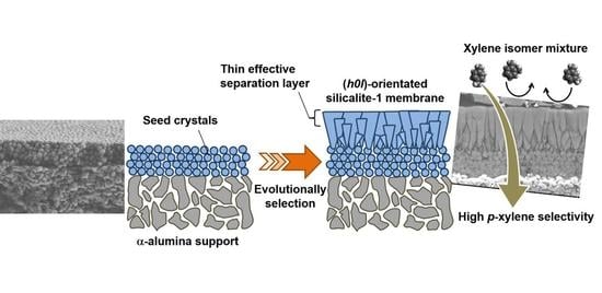
Formation Process of Columnar Grown (101)-Oriented Silicalite-1 Membrane and Its Separation Property for Xylene Isomer

1
Research Organization for Nano and Life Innovation, Waseda University, 513 Waseda-Tsurumaki-cho, Shinjuku-ku, Tokyo 162-0041, Japan
2
Department of Applied Chemistry, Waseda University, 513 Waseda-Tsurumaki-cho, Shinjuku-ku, Tokyo 162-0041, Japan
3
Nanostructures Research Laboratory, Japan Fine Ceramics Center, 2-4-1 Atsuta-ku, Nagoya-shi, Aichi 456-8587, Japan
4
Advanced Research Institute for Science and Engineering, Waseda University, 3-4-1 Okubo, Shinjuku-ku, Tokyo 169-8555, Japan
*
Author to whom correspondence should be addressed.
Submission received: 16 September 2020 / Revised: 15 October 2020 / Accepted: 16 October 2020 / Published: 17 October 2020
(This article belongs to the Special Issue Zeolites)

Abstract

:
Silicalite-1 membrane was prepared on an outer surface of a tubular α-alumina support by a secondary growth method. Changes of defect amount and crystallinity during secondary growth were carefully observed. The defect-less well-crystallized silicalite-1 membrane was obtained after 7-days crystallization at 373 K. The silicalite-1 membrane became (h0l)-orientation with increasing membrane thickness, possibly because the orientation was attributable to “evolutionally selection”. The (h0l)-oriented silicalite-1 membrane showed high p-xylene separation performance for a xylene isomer mixture (o-/m-/p-xylene = 0.4/0.4/0.4 kPa). The p-xylene permeance through the membrane was 6.52 × 10⁻⁸ mol m−2 s−1 Pa−1 with separation factors αp/o, αp/m of more than 100 at 373 K. As a result of microscopic analysis, it was suggested that a very thin part in the vicinity of surface played as effective separation layer and could contribute to high permeation performance.

Graphical Abstract

1. Introduction

The separation and purification process requires a huge amount of energy in petroleum and petrochemical fields. To reduce energy consumption, an energy-saving process for hydrocarbon separation is desired. Membrane separation and distillation-membrane hybrid separation techniques are expected as promised novel energy-efficient processes [1]. Although many kinds of polymeric membranes have been widely used for gas separation and water treatment, polymeric membranes are hardly used for hydrocarbon separation due to their scarce thermal, and chemical resistance required for membrane materials used in petroleum and petrochemical industries. Therefore, inorganic membranes such as silica [2,3], carbon molecular sieve [4,5], and zeolite [6,7,8,9,10,11] for hydrocarbon separation have been extensively studied for recent decades due to their high stability. In particular, zeolite is one of the most promised membrane materials since zeolite has unique molecular sieving properties based on its uniformly sized micropore.
MFI-type zeolite is one of the most popular synthetic zeolites with straight channels (0.56 × 0.53 nm) along b-axis and sinusoidal channels (0.51 × 0.55 nm) along a-axis [12,13]. As these pore sizes are close to sizes of middle hydrocarbons, an MFI-type zeolite membrane is anticipated to separate these mixtures by the molecular sieving effect. Therefore, much research on the separation of ethanol/water [14], butane isomer [6], hexane isomer [6,7], and xylene isomer [6,8,9,10,11] with MFI-type zeolite membranes have been reported. Xylene isomer separation is particularly important, however a difficult target of the MFI-type zeolite. Whereas the demand for p-xylene as feedstocks of polyesters is larger than those of the other isomers, p-xylene selectivity in isomerization is limited to 20% by thermodynamic equilibria under common reaction conditions. For this reason, p-xylene is separated from large amounts of other xylene isomers.
The principle of p-xylene separation from xylene isomer mixture by using the MFI-type zeolite membrane is the molecular sieving effect that enables us to separate them by size. In other words, p-xylene preferentially penetrates through the MFI-type zeolite membrane because a diffusivity of p-xylene is a magnitude larger than those of the other isomers owing to its small molecular size. To exhibit such size-exclusion ability, the MFI-type zeolite membrane has to be synthesized with very few defects.
Preparation methods of defect-less membranes have been widely studied for the last decades. In particular, the calcination step is quite an important problem for the preparation of membranes with high separation ability. Calcination is necessary to remove the organic structure-directing agent (OSDA) to activate the micropore of the MFI-type zeolite membrane prior to use. However, crack formation often occurs in the calcination step due to the large differences in thermal expansion coefficients between support and membrane, or by the volume change in the zeolite crystal followed by removal of OSDA [15,16]. It had been reported that membrane thickness strongly influenced crack formation in the calcination step [17,18]. Thicker membranes are easily broken by calcination and spoiled their size exclusion ability. Hedlund et al. pointed out that a thin membrane layer contributes to obtaining a defect-free membrane because these membranes hardly collapsed in calcination steps [17].
Because p-xylene permeance through membranes were still insufficient for practical use, improvement of the permeance is an important issue in development as well. To enlarge p-xylene permeance many researchers have focused on crystal orientation and membrane thickness. Lai et al. reported a preparation method of oriented silicalite-1, a pure silica MFI-type zeolite, membranes [9,10]. In their study, a b-oriented silicalite-1 membrane where through-pores existed vertically to the support surface showed high p-xylene permeance for xylene isomer separation. Hedlund et al. prepared an ultra-thin MFI-type zeolite membrane by using the masking technique [6,19]. In their masking technique, the pores of porous support were plugged with polymethyl methacrylate (PMMA) prior to crystallization to avoid the formation of resistance layer, amorphous, and/or crystals, inside of support. The PMMA was removed and an ultra-thin, ca. 500 nm, membrane layer remained on the surface of support after crystallization. The ultra-thin membrane exhibited high permeance for C4–C8 hydrocarbon separation. Recently, Tsapatsis et al. reported the b-oriented MFI nanosheet membrane with the thickness of ca. 200 nm [20,21]. Their nanosheet membrane exhibited the p-xylene permeance of 2.9 × 10⁻⁸ mol m−2 s−1 Pa−1 from o- and p-xylene mixture with separation factor of ca 8000 at 423 K.
These reports described above clearly showed that controlling crystal orientation and reducing membrane thickness were effective approaches for improvement of permeation ability. However, such preparation methods are complicated to apply in practical use and lead to escalating a membrane cost. Here, we suppose a simple synthesis method of a silicalite-1 membrane with a thin effective separation layer by a secondary growth method along with two strategies. The seed crystal is only loaded on an outer surface of the support to avoid the formation of a resistance layer inside the support and to obtain a highly permeable membrane. In addition, the seed crystal is grown by hydrothermal treatment in relatively mild conditions in which nucleation hardly occurs and crystals slowly grow. As soon as defects among crystals are occluded, hydrothermal treatment is stopped, resulting in that a membrane having a thin compact layer will be obtained.
In this study, the formation process of the silicalite-1 membrane was carefully observed. Changes in defect amount and separation property were specifically investigated. In addition, permeation and separation properties for xylene isomer mixture were evaluated.

2. Experimental

2.1. Preparations of Seed Crystal and Seeded Support

Silicalite-1 membranes were synthesized by a secondary growth method. Seed crystal and seed slurry for preparation of seeded support were prepared as follows.
Synthesis solution of 25SiO2:2(TPA)2O:1100H2O:100EtOH:0.1Na2O [22] was prepared by mixing of tetraethylorthosilicate (TEOS, 98 wt.%, Merck Co., Gernsheim, Germany), tetrapropylammonium hydroxide solution (TPAOH, 1.0 M, Sigma-Aldrich Co., Missouri, US), distilled water and sodium hydroxide (97%, Kanto Chemical, Tokyo, Japan). TEOS was slowly added into a mixture of the other chemicals, and the obtained synthesis solution was aged at room temperature for 24 h under stirring condition before a hydrothermal treatment. The hydrothermal treatment was carried out at 373 K for 24 h. After crystallization, white precipitation was procured by a filtration. The filtered powder was washed by boiling water and dried at 383 K overnight. Finally, silicalite-1 seed crystal was obtained. Organic structure-directing agents (OSDA) were removed in the seed crystal by calcination at 773 K for 8 h prior to preparing seed slurry. The calcined crystal was dispersed in an appropriate amount of distilled water to form the slurry. A solid content in the slurry was adjusted at 5.0 g L−1.
Seeded support was prepared by a dip-coating method using the seed slurry. Seed crystal was loaded on an outer surface of tubular α-alumina support (i.d. = 7.0 mm, o.d. = 10 mm, average pore size = 150 nm, NORITAKE Ltd., Nagoya, Japan). Both ends of tubular support were plugged with polytetrafluoroethylene caps to avoid penetration of the slurry. Support was dipped in the slurry for 1 min, withdrawn vertically at ca. 3 cm s−1, and then dried at 343 K over 40 min. This process was run twice. The dip-coated support was calcined at 773 K for 2 h to bind seed crystals on a support surface during secondary growth. Finally, seeded support was obtained.

2.2. Membrane Preparation

Silicalite-1 membranes were prepared on an outer surface of tubular support by a secondary growth method as follows.
The seeded tubular support calcined was placed vertically in a PTFE-lined stainless-steel autoclave with a synthesis solution. The synthesis solution had the molar composition of 25SiO2:1.5(TPA)2O:1650H2O:200EtOH and was prepared by mixing TEOS, TPAOH, distilled water, and ethanol (99.5 wt.%, Kanto Chemical Co.). TEOS was slowly added into a mixture of the other chemicals as in the case of seed crystal preparation. This solution was aged under the stirring condition at 333 K for 4 h prior to use. The autoclave was closed and placed in a preheated oven for hydrothermal crystallization at 373 K. Crystallization periods were changed from 6 to 336 h (6, 24, 72, 120, 168, 252, and 336 h) to investigate a membrane formation process. After crystallization, the membranes were washed with boiling water and dried at 383 K overnight. The silicalite-1 membrane was calcined at 773 K for 8 h to remove OSDA before use in separation tests and characterizations.

2.3. Microscopic Observations

Membrane shape, thickness, and orientation were observed by using field emission scanning electron microscopy (FE-SEM, S-4800, Hitachi, Japan) and X-ray diffraction (XRD) measurement (Ultima IV, Rigaku, Japan).
Zeolite membranes were also observed using transmission electron microscopes (TEM). TEM samples were prepared by the ion milling method with Ar ions. The observations were performed using a JEOL JEM-2010 microscope at an accelerating voltage of 200 kV. Low dose irradiation conditions were necessary to avoid damage to the zeolite structure.

2.4. N2 Adsorption Measurement

Micropore volume was evaluated by non-destructive N2 adsorption measurement. The measurement was performed by using BELSORP-max (MicrotracBEL Corp., Osak, Japan) with a special sample holder which enables us to insert a whole membrane without destruction [23]. The samples were outgassed at 623 K for 8 h under vacuum conditions prior to the adsorption test. Adsorption measurements were carried out at 77 K.

2.5. Nano-Permporometry Test

Nano-permporometry was performed by using Porometer nano-6 (MicrotracBEL Corp., Osak, Japan ). Permeate flow rate of inert gas through the membrane was measured while the relative pressure of vapor was increased in a step-wise manner. In this process, pores in the membrane were plugged by condensation of vapor in the order of pore size from smallest to largest, and then permeate flow rate of inert gas decreased. Pore size distribution could be calculated by a relationship between the relative pressure of vapor and flow rate.
Thermal treatment at 573 K for 2 h was taken place to remove any adsorbed molecules before the nano-permporometry test. The nano-permporometry test was carried out at 333 K with relative pressure of vapor from 0 to 0.2. In the measurement, helium and n-hexane were used for inert gas and condensable vapor, respectively.

2.6. Permeation Test

Permeation test was carried out in vapor permeation mode. Hydrocarbon mixture was pumped into pre-heater to vaporize and the vapor was fed to the outer surface of tubular support. The membrane temperature was controlled by using a heating jacket. Permeate side was swept with amounts of flowing gas, argon. Both the feed and permeate sides were kept at atmospheric pressure. Permeate flow rate was determined by gas chromatography (GC-8A, Shimadzu, Tokyo, Japan) using internal standard gas, methane.
Flux, J and permeance, Π was calculated using the following Equations (1) and (2):
J (mol m−2 s−1) = u A−1
Π (mol m−2 s−1 Pa−1) = J Δp−1
where u is the flow rate (mol s−1), A is the membrane area (m2) and Δp is the partial pressure difference between the feed and permeate sides (Pa). The separation factor α was calculated from the following Equation (3):
αA/B = (YA / YB) / (XA / XB)
where XA and XB are mol fraction of component A and B in the feed. YA and YB are mol fraction of component A and B in permeate, respectively.

3. Results and Discussion

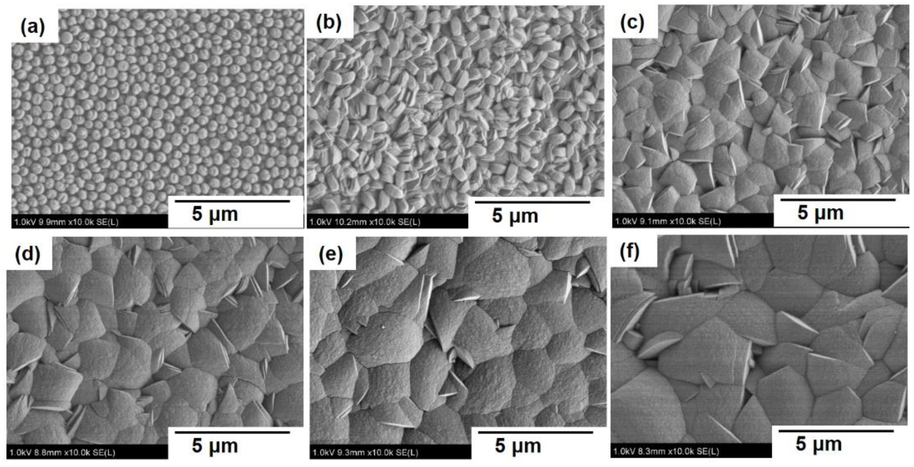
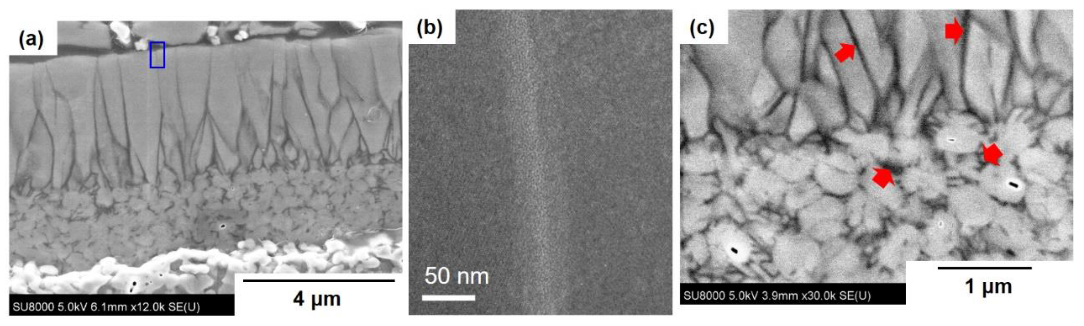
3.1. Microscopic Observation of Membrane Formation

Microscopic analysis by using FE-SEM was adopted to observe the change in the appearance of silicalite-1 membranes during secondary growth. Figure 1 and Figure 2 show typical FE-SEM images of seeded support and silicalite-1 membranes with different crystallization periods. Solid and dashed lines in Figure 2 are guides for the eye, and they show the seed crystal layer and columnar crystal layer appeared in the secondary growth step, respectively.
Spherical seeds with a diameter of ca. 300 nm orderly covered an outer surface of porous support with several layers as shown in Figure 1a. Judging from the cross-sectional view in Figure 2a, the thickness of the seed layer was about 2 μm. On the other hand, seed crystals were hardly observed inside of the support. Distribution of particle size in the slurry used for dip-coating was measured by a dynamic light scattering (DLS) method (ELSZ-1000ZS, Otsuka Electronics, Kyoto, Japan). The particle size had a narrow distribution from 200 to 500 nm (see Figure S1 in Supplementary materials). It is noted that the particle size in the slurry was larger than the average pore size of 150 nm in the support, resulting in that seed crystals hardly entered through the pore of support. In addition, the particle size in a slurry measured by the DLS was almost the same as the crystal size observed in FE-SEM images, suggesting that seed crystal was well dispersed in the seed slurry. For these reasons, seed crystals would be uniformly supported only on an outer surface by a dip-coating method.
The growth of outermost crystals from the seed layer was followed from the top-view images shown in Figure 1b–f. In the early stage of a secondary growth step up to 72 h, the shape of the crystal was little increased around 500 nm and the facet of crystal became to be observed. The size of surface crystal increased and the number of the visible crystals decreased with prolonging the secondary growth period. After 336 h crystallization, the size of the surface crystal finally reached around 2 μm which is an order of magnitude larger than that of the seed crystal. In addition, defects among crystals were hardly observed judging from FE-SEM images after 120 h crystallization.
The formation of the columnar growth layer was clearly observed from cross-sectional views shown in Figure 2b–f. Although crystal size and shape changed in the top-view image of the membrane crystallized for 72 h, the growth layer was yet to be observed from a cross-sectional view. After 120 h crystallization, crystal growth progressed from the outermost crystals on the seed layer. For membranes crystallized for 120 h and more, the thickness of the columnar growth layer increased with an increasing crystallization period. The thickness of the columnar growth layer increased almost linearly, and then these values of membranes crystallized for 120, 168, 252, and 336 h were approximately 2.5, 4.0, 6.0, and 7.5 μm, respectively. In contrast, nucleation and crystal growth hardly observed toward the inside of a support. Loading of seed crystal only an outer surface and relatively mild conditions of secondary growth could contribute to inhibition of nucleation inside a support.
The silicalite-1 membranes shown in Figure 1 and Figure 2 were prepared by using calcined seeded support. Here, we discuss the effect of calcination after dip-coating on the secondary growth process. Seeded support without calcination after dip-coating was immersed into a synthesis solution for 10 min, and then the surface was observed by FE-SEM (see Figure S2 in Supplementary materials). As a result, the seed crystal layer was partially peeled and a bare support surface was observed. In contrast, a bare surface was not observed on calcined seeded support as shown in Figure 1a, indicating that the calcination for seeded support would contribute to inhibit peeling the seed layer in hydrothermal treatment as a previous report by Pan and Lin [24].

3.2. Changes of Crystallinity and Orientation

Change of zeolite pore volume which was an index of crystallinity was measured by non-destructive N2 adsorption. Zeolite pore volumes in silicalite-1 membranes were calculated as follows. The Amount of N2 adsorbed at p ps−1 = 1 × 10⁻⁴ was adopted as a saturated adsorbed amount for zeolite pore because this amount meant saturated adsorbed amount for a cylindrical pore with diameter 0.55 nm which was almost the same as the pore size of MFI-type zeolite in Saito-Foley model [25,26].
Figure 3a shows adsorption isotherms on silicalite-1 seed crystal and membranes. Figure 3b shows the calculated zeolite pore volumes from the isotherms in each sample. In Figure 3b, a plot at the crystallization period of 0 and dashed line show the zeolite pore volumes of the seed crystal. At first, seed crystals had 0.118 cm3 g−1 zeolite pore volume before crystallization. With the onset of crystallization, zeolite pore volumes in a membrane declined about 30% in the early stage. For example, the volume was 0.081 cm3 g−1 in 72 h crystallized membrane. This would be caused by the partial dissolution of seed crystals and the generation of amorphous and crystals having low crystallinity. In contrast, zeolite pore volumes swelled in the later stage. The volume in the membrane crystallized for 168 and 336 h were 0.107 and 0.124 cm3 g−1. As a result, the volume overtook that of seed crystal with prolonging the crystallization period. It indicated that most of the generated materials in the later stage had high crystallinity, in other words, the whole of a membrane consisted of well-crystallized silicalite-1.
Figure 4 shows XRD patterns of seeded support and silicalite-1 membranes and Figure 5 shows membrane weight and thickness of the columnar crystal layer as a function of the crystallization period. The intensity of each peak was almost constant until 72 h crystallization as shown in Figure 4. At a later stage in the secondary growth step, the intensity increased with the prolonging crystallization period. This result is consistent with the pore volume change in the N2 adsorption test and the observation by FE-SEM. On the other hand, weight gain was observed from the early phase in the crystallization period as shown in Figure 5. These results strongly suggest that amorphous and crystal having low crystallinity generated up to 72 h crystallization, resulting in that pore volume per unit weight decreased in early times.
Here, we discuss the orientation of the silicalite-1 membrane obtained from XRD results and selected area diffraction patterns by using TEM. Judging from the XRD results, the intensity ratio of (101) to (020) increased as the growth of the columnar crystal layer. The ratio of (101) to (020) in membranes crystallized for 72, 168 and 336 h were 1.0, 2.0, and 6.5, respectively. In addition, electron diffraction patterns derived from (202), (002), and (200) were observed as shown in Figure 6, meaning that the surface of the layer consisted of (h0l) plane. We deduce that the appearance of (h0l)-orientation is attributable to “evolutionally selection” as in the case of (001)-oriented MOR-type zeolite membrane preparation by a secondary growth method [27].
An orientation by “evolutionally selection” appears as follows. Anisotropic crystal generally has a different growth rate along each axis. At the early stage of secondary growth, seeds can freely grow in all directions because the seed layer had no distinct orientation. When the axis of the highest growth rate in a crystal lies on a support, the crystal collides against a lateral side of another crystal and its crystal growth stops. Finally, crystals which have the axis of highest growth rate perpendicular to support are selected and continue to grow in “evolutionally selection” mode. In that case, many crystals are embedded under the growing layer and the number of outermost crystals decreased by the selection as shown in Figure 1 and Figure 2. A schematic diagram of evolutional selection was drawn in Figure S3 in Supplementary materials.

3.3. Molecular Sieving Properties and Defect Amount

Separation test for an equimolar mixture (50:50 kPa) of n-hexane (n-Hex) and 2,2-dimethylbutane (DMB) was carried out at 573 K in vapor permeation mode for silicalite-1 membranes with different crystallization period. The separation factor of n-Hex/DMB (αn-Hex/DBM) was a kind of index for the molecular sieving property of the silicalite-1 membrane. DMB has a kinetic diameter of 0.63 nm which is close to the pore size of silicalite-1 [28]. Its diffusivity in micropore of silicalite-1 is three orders of magnitude smaller than that of n-Hex with a kinetic diameter of 0.43 nm [29]. In other words, the defect-less silicalite-1 membrane exhibits superior n-Hex selectivity based on the molecular sieving effect.
Figure 7 shows the results of separation tests for n-Hex and DMB mixture. Permeation and separation performance drastically changed by the crystallization period. Although n-Hex permeance was almost constant, DMB permeance changed by orders of magnitude. DMB permeance decreased with an increasing crystallization period up to 168 h. The permeance were 45.8, 0.466, and 0.169 × 10⁻⁹ mol m−2 s−1 Pa−1 through membranes crystallized for 72, 120, and 168 h, respectively. On the other hand, DMB permeance increased through membrane crystallized for 252 h and more. As a result, DMB permeance had a minimum value at a crystallization period of 168 h, and then the separation factor had the maximum value of 781 at that time.
To investigate the reason for the difference in separation ability, the number of defects in each silicalite-1 membrane was evaluated by using nano-permporometry. Kelvin equation shown in Equation (4) was used to estimate pore size in prepared membranes from the results of the nano-permporometry test.
DK = −4 ν σ cosθ (R T ln(p ps−1))−1
where, DK, ν, σ, θ, R, T and p ps−1 represent Kelvin diameter [m], molar volume [m3 mol−1], surface tension [kg s−2], contact angle [°], gas constant [m2 kg s−2 K−1 mol−1], temperature [K] and relative pressure of condensable vapor [-], respectively. Here we assumed that the contact angle θ is 0°. Although the Kelvin equation cannot be adapted to micropore theoretically, good agreement of the equation in micropore was previously reported [30]. When p ps−1 is 0.7 × 10⁻³, kelvin diameter derived from Equation (4) shows 0.55 nm which is almost the same as the pore size of silicalite-1. Therefore, helium permeation through defect-free membrane should be completely blocked by condense of vapor in micropore above p ps−1 of 0.7 × 10⁻³.
Figure 8 shows the results of nano-permporometry tests for membranes with different crystallization period. The dashed line shows a quantification limit of helium permeance at 1.0 × 10⁻⁹ mol m−2 s−1 Pa−1. Helium permeance was almost constant through a membrane crystallized for 24 h despite the concentration of condensable vapor, suggesting that many defects among crystals remained after the secondary growth. Similarly, many defects still remained even after 72 h crystallization. Because of such insufficient crystal growth, the membrane prepared with a shorter crystallization period showed quite a low separation performance in the separation test.
On the other hand, helium permeance decreased above p ps−1 of 4.0 × 10⁻³ through membranes crystallized over 120 h which exhibited good molecular sieving properties as shown in Figure 7. The decrease of helium permeance means that very few defects among crystals remained in these membranes.
Here we defined a ratio of the non-zeolitic pathway to all pathways for quantitative discussion about the effect of the non-zeolitic pathway on molecular sieving ability. The ratio of the non-zeolitic pathway was calculated as dividing helium permeance at p ps−1 of 0.2 by the permeance at p ps−1 of 0 according to a previous report by Hedlund et al. [6]. Helium permeance at p ps−1 of 0 means the permeance through all pathways. Besides, helium permeance at p ps−1 of 0.2 means through non-zeolitic pathway having more than ca. 2 nm of diameter determined based on the Kelvin equation. Therefore, the ratio of the non-zeolitic pathway was larger than 2 nm to all pathways can be evaluated.
A relationship between the calculated ratio of non-zeolitic pathway and separation factor, αn-Hex/DMB was shown in Figure 9. The ratio drastically decreased from 0.27 to 2.7 × 10⁻³ between the crystallization period of 72 and 120 h, suggesting that most of the defects among crystals were occluded in this term. This ratio had a minimum (<2.0 × 10⁻³) in the membrane crystallized for 168 h. After that, the ratio increased with increasing crystallization period up to 336 h; the ratios are 2.8 × 10⁻³ and 1.4 × 10⁻² in membranes crystallized for 252 and 336 h, respectively. It suggests that defects are newly generated in these membranes for any reason which is discussed in the following section. At any rate, a relationship between the ratio of non-zeolitic pathway and separation factor, αn-Hex/DMB clearly showed that separation ability of silicalite-1 membrane by molecular sieving effect was dominated by the amount of non-zeolitic pathway in a membrane. It is noteworthy that only 1% of the non-zeolitic pathway well spoiled a molecular sieving property of the silicalite-1 membrane.
We shed light on the reason for defects appearance in membranes crystallized over 252 h. Nano-permporometry tests were also performed for these membranes before calcination, and then amounts of non-zeolitic pathways were compared between before and after calcination. As a result, helium hardly penetrated through both 252 and 336 h crystallized membranes before calcination, suggesting that these membranes had very few non-zeolitic pathways. The result showed that crack must be formed in these membranes in the calcination step. There are many reports about crack formation in zeolite membranes in the calcination step to remove OSDA described in the introduction section [15,16,17,18]. The thicker membrane would have larger stress by thermal expansion of support and volume change of crystals, resulting in that crack formed in membranes prepared with longer crystallization period.

3.4. Xylene Isomer Separation

Finally, the separation test of xylene isomer mixture was performed for the silicalite-1 membrane crystallized for 168 h. o-, m-, p-Xylene equimolar mixture (0.4:0.4:0.4 kPa) was fed to the membrane with dilution gas, Argon. The membrane temperature was adjusted at 373 K.
Table 1 listed the results of xylene isomer separation tests. Our silicalite-1 membrane showed p-xylene permeance of 6.52 × 10⁻⁸ mol m−2 s−1 Pa−1 with o- and m-xylene permeances below quantification limit of 6.0× 10⁻¹⁰ mol m−2 s−1 Pa−1, resulting in that separation factors, αp/o and αp/m of above 100. The (h0l)-oriented silicalite-1 membrane prepared by a simple secondary growth method exhibited good permeation and separation performance compared with MFI-type zeolite membranes previously reported as shown in Table 1 [6,8,9,10,11,20,21].
Prepared (h0l)-oriented membrane exhibited relatively high permeation performance despite the large membrane thickness of ca. 6 μm including the seed layer as shown in Figure 2b. The reason for high permeation performance was discussed from the microstructure of the obtained membrane as shown in Figure 10. As a result of microscopic analysis, many defects among crystals remained in the seed layer after 168 h crystallization. In addition, many grain boundaries existed inside of columnar crystal layer along the direction as molecular permeation. However, the membrane crystallized for 168 h exhibited superior separation performance based on a molecular sieving effect, suggesting that the grain boundaries would not penetrate through the membrane. From the enlarged view of grain boundary near-surface, as shown in Figure 10b, the grain boundary between two crystals was plugged with a thin amorphous layer. From these results, we conclude that only a very thin part in the vicinity of the surface is compact without defects and plays as an effective separation layer. The thin effective layer less than 1 μm can contribute to high permeation performance. The deduced model of a formation process of the silicalite-1 membrane is shown in Figure 11.

4. Conclusions

The silicalite-1 tubular membrane was prepared by a simple secondary growth method and its formation process was discussed.
Uniformly ordered seed crystals and relatively mild conditions of secondary growth could contribute to forming a columnar growth layer on the outermost crystal of the seed layer. In addition, the columnar growth layer showed (h0l)-orientation, possibly because the orientation is attributable to “evolutionally selection”.
Change of defect amount and separation performance during secondary growth were investigated by using nano-permporometry and hydrocarbon separation tests. Most of the defects among crystals were occluded between crystallization periods of 72 to 168 h. Separation performance was spoiled in membranes crystallized over 252 h by the crack formation in the calcination step to remove OSDA, suggesting that thicker membranes would have larger stress by thermal treatment. As a result, the membrane crystallized for 168 h showed maximum separation factor αn-Hex/DMB of 781 for the equimolar mixture of n-hexane and 2,2-dimethylbutane by molecular sieving effect. From a microscopic analysis, it was suggested that a very thin part in the vicinity of the surface was an effective separation layer.
Separation performance from xylene isomer mixture (o-/m-/p-xylene = 0.4/0.4/0.4 kPa) through the silicalite-1 membrane was evaluated. p-Xylene permeance through the membrane was 6.52 × 10⁻⁸ mol m−2 s−1 Pa−1 with separation factors αp/o, αp/m of more than 100 at 373 K. Our (h0l)-oriented silicalite-1 membrane prepared by a simple secondary growth method exhibited good permeation and separation performance for xylene isomer mixture compared with MFI-type zeolite membranes previously reported.

Supplementary Materials

The following are available online at https://0-www-mdpi-com.brum.beds.ac.uk/2073-4352/10/10/949/s1, Figure S1: Particle size distribution in seed slurry for dip-coating. Figure S2: Typical FE-SEM images of the surface of seeded supports immersed into synthesis solution without calcination after dip-coating: (a) wide and (b) enlarged view. Figure S3: A schematic diagram of evolutional selection. Figure S4: Results of nano-permporometry tests for silicalite-1 membranes crystallized for O 252; ⧠, 336 h before calcination.

Author Contributions

Conceptualization, M.S. (Motomu Sakai); methodology, M.S. (Motomu Sakai), T.K., M.S., (Miyuki Sekigawa) and Y.S.; validation, M.S. (Motomu Sakai), Y.S. and M.M.; investigation, M.S. (Motomu Sakai), Y.S. and M.M.; resources, Y.S. and M.M.; data curation, M.S. (Motomu Sakai) and Y.S.; writing—original draft preparation, M.S. (Motomu Sakai); supervision, M.M.; project administration, M.M.; funding acquisition, M.M. All authors have read and agreed to the published version of the manuscript.

Funding

This research was partially supported by JST-CREST (Japan Science and Technology Agency, Create REvolutionary technological seeds for Science and Technology innovation program), Grant Number JPMJCR1324, Japan.

Conflicts of Interest

The authors declare no conflict of interest.

References

  1. Sholl, D.S.; Lively, R.P. Seven chemical separations to change the world. Nature 2016, 532, 435–437. [Google Scholar] [CrossRef]
  2. Kanezashi, M.; Shazwani, W.N.; Yoshioka, T.; Tsuru, T. Separation of propylene/propane binary mixtures by bis(triethoxysilyl) methane (BTESM)-dericed silica membranes fabricated at different calcination temperatures. J. Membr. Sci. 2012, 415–416, 478–485. [Google Scholar] [CrossRef]
  3. Ikeda, A.; Nomura, M. Preparation of Amorphous Silica Based Membranes for Separation of Hydrocarbons. J. Jpn. Petrol. Inst. 2016, 59, 259–265. [Google Scholar] [CrossRef] [Green Version]
  4. Xu, L.; Rungta, M.; Koros, W.J. Matrimid® derived carbon molecular sieve hollow fiber membranes for ethylene/ethane separation. J. Membr. Sci. 2011, 380, 138–147. [Google Scholar] [CrossRef]
  5. Hayashi, J.; Mizuta, H.; Yamamoto, M.; Kusakabe, K.; Morooka, S.; Suh, S.-H. Separation of Ethane/Ethylene and Propane/Propylene Systems with a Carbonized BPDA-pp’ODA Polyimide Membrane. Ind. Eng. Chem. Res. 1996, 35, 4176–4181. [Google Scholar] [CrossRef]
  6. Hedlund, J.; Sterte, J.; Anthonis, M.; Bons, A.-J.; Carstensen, B.; Corcoran, N.; Cox, D.; Deckman, H.; Gijnst, W.D.; Moor, P.-P.; et al. High-flux MFI membranes. Microporous Mesoporous Mater. 2002, 52, 179–189. [Google Scholar] [CrossRef]
  7. Funke, H.H.; Argo, A.M.; Falconer, J.L.; Noble, R.D. Separations of Cyclic, Branched, and Linear Hydrocarbon Mixtures through Silicalite Membranes. Ind. Eng. Chem. Res. 1997, 334, 137–143. [Google Scholar] [CrossRef]
  8. Tarditi, A.M.; Lombardo, E.A. Influence of exchanged cations (Na+, Cs+, Sr2+ and Ba2+) on xylene permeation through ZSM-5/SS tubular membranes. Sep. Purif. Technol. 2008, 61, 136–147. [Google Scholar] [CrossRef]
  9. Lai, Z.; Bonilla, G.; Diaz, I.; Nery, J.G.; Sujaoti, K.; Amat, M.A.; Kokkoli, E.; Terasaki, O.; Thompson, R.W.; Tsapatsis, M.; et al. Microstructural Optimization of a Zeolite Membrane for Organic Vapor Separation. Science 2003, 300, 456–460. [Google Scholar]
  10. Lai, Z.; Tsapatsis, M.; Nicolich, J.P. Siliceous ZSM-5 Membranes by Secondary Growth of b-Oriented Seed Layers. Adv. Funct. Mater. 2004, 14, 716–729. [Google Scholar] [CrossRef]
  11. Daramola, M.O.; Burger, A.J.; Giroir-Fendler, A.; Miachon, S.; Lorenzen, L. Extractor-type catalytic membrane reactor with nanocomposite MFI-alumina membrane tube as separation unit: Prospect for ultra-pure para-Xylene production from m-Xylene isomerization over Pt-HZSM-5 catalyst. Appl. Catal., A 2010, 386, 109–115. [Google Scholar] [CrossRef]
  12. Kokotailo, G.T.; Lawton, S.L.; Olson, D.H.; Meier, W.M. Structure of synthetic zeolite ZSM-5. Nature 1978, 272, 437–438. [Google Scholar] [CrossRef]
  13. Olson, D.H.; Kokotailo, G.T.; Lawton, S.L.; Meler, W.M. Crystal Structure and Structural-Related Properties of ZSM-5. J. Phys. Chem. 1981, 85, 2238–2243. [Google Scholar] [CrossRef]
  14. Ueno, K.; Negishi, H.; Okano, T.; Tawarayama, H.; Ishikawa, S.; Miyamoto, M.; Uemiya, S.; Ouni, Y. Effects of Silica-Particle Coating on Silica Support for the Fabrication of High-Performance Silicalite-1 Membranes by Gel-Free Steam-Assisted Conversion. Membranes 2019, 9, 46. [Google Scholar] [CrossRef] [PubMed] [Green Version]
  15. Dong, J.; Lin, Y.S.; Hu, M.Z.-C.; Peascoe, R.A.; Payzant, E.A. Template-removal-associated microstructural development of porous-ceramics-supported MFI zeolite membranes. Microporous Mesoporous Mater. 2000, 34, 241–253. [Google Scholar] [CrossRef]
  16. Choi, J.; Jeong, H.-K.; Snyder, M.A.; Stoeger, J.A.; Masel, R.I.; Tsapatsis, M. Grain Boundary Defect Elimination in a Zeolite Membrane by Rapid Thermal Processing. Science 2009, 325, 590–593. [Google Scholar] [CrossRef]
  17. Akhtar, F.; Ojuva, A.; Wirawan, S.K.; Hedlund, J.; Bergstrom, L. Hierarchically porous binder-free silicalite-1 discs: A novel support for all-zeolite membranes. J. Mater. Chem. 2011, 21, 8822–8828. [Google Scholar] [CrossRef]
  18. Akhtar, F.; Sjoberg, E.; Korelskiy, D.; Rayson, M.; Hedlund, J.; Bergstrom, L. Preparation of graded silicalite-1 substrates for all-zeolite membranes with excellent CO2/H2 separation performance. J. Membr. Sci. 2015, 493, 206–211. [Google Scholar] [CrossRef] [Green Version]
  19. Hedlund, J.; Jareman, F.; Bons, A.-J.; Anthonis, M. A masking technique for high quality MFI membranes. J. Membr. Sci. 2003, 222, 163–179. [Google Scholar] [CrossRef]
  20. Jeon, M.Y.; Kim, D.; Kumar, P.; Lee, P.S.; Rangnekar, N.; Bai, P.; Shete, M.; Elyassi, B.; Lee, H.S.; Narasimharao, K.; et al. Ultra-selective high-flux membranes from directly synthesized zeolite nanosheets. Nature 2017, 543, 690–694. [Google Scholar] [CrossRef]
  21. Kim, D.; Jeon, M.Y.; Stottrup, B.L.; Tsapatsis, M. para-Xylene Ultra-selective Zeolite MFI Membranes Fabricated from Nanosheet Monolayers at the Air–Water Interface. Angew. Chem. Int. Ed. 2018, 57, 480–485. [Google Scholar] [CrossRef] [PubMed]
  22. Ren, N.; Bronic, J.; Subotic, B.; Lv, X.-C.; Yang, Z.-J.; Tang, Y. Controllable and SDA-free synthesis of sub-micrometer sized zeolite ZSM-5. Part 1: Influence of alkalinity on the structural, particulate and chemical properties of the products. Microporous Mesoporous Mater. 2011, 139, 197–206. [Google Scholar] [CrossRef]
  23. Sakai, M.; Fujimaki, N.; Kobayashi, G.; Yasuda, N.; Oshima, Y.; Seshimo, M.; Matsukata, M. Formation process of *BEA-type zeolite membrane under OSDA-free conditions and its separation property. Microporous Mesoporous Mater. 2019, 284, 360–365. [Google Scholar] [CrossRef]
  24. Pan, M.; Lin, Y.S. Template-free secondary growth synthesis of MFI type zeolite membrane. Microporous Mesoporous Mater. 2001, 43, 319–327. [Google Scholar] [CrossRef]
  25. Saito, A.; Foley, H.C. Curvature and Parametric Sensitivity in Models for Adsorption in Micropores. AIChE J. 1991, 37, 429–436. [Google Scholar] [CrossRef]
  26. Saito, A.; Foley, H.C. Argon porosimetry of selected molecular sieves: Experiments and examination of the adapted Horvath-Kawazoe model. Microporous Mater. 1995, 3, 531–542. [Google Scholar] [CrossRef]
  27. Li, G.; Kikuchi, E.; Matsukata, M. The control of phase and orientation in zeolite membranes by the secondary growth method. Microporous Mesoporous Mater. 2003, 62, 211–220. [Google Scholar] [CrossRef]
  28. Sommer, S.; Melin, T.; Falconer, J.L.; Noble, R.D. Transport of C6 isomers through ZSM-5 zeolite membranes. J. Membr. Sci. 2003, 224, 51–67. [Google Scholar] [CrossRef]
  29. Cavalcante, L., Jr.; Ruthven, D.M. Adsorption of Branched and Cyclic Paraffins in Silicalite. 2. Kinetics. Ind. Eng. Chem. Res. 1995, 34, 185–191. [Google Scholar] [CrossRef]
  30. Tsuru, T.; Hino, T.; Yoshioka, T.; Asaeda, M. Permporometry characterization of microporous ceramic membranes. J. Membr. Sci. 2001, 186, 257–265. [Google Scholar] [CrossRef]
Figure 1. Typical FE-SEM images of surface of (a) a seeded support and silicalite-1 membranes crystallized for (b) 72, (c) 120, (d) 168, (e) 252, and (f) 336 h.
Crystals 10 00949 g001
Figure 2. Typical FE-SEM images of cross-section of (a) a seeded support and silicalite-1 membranes crystallized for (b) 72, (c) 120, (d) 168, (e) 252, and (f) 336 h.
Crystals 10 00949 g002
Figure 3. Results of non-destructive N2 adsorption test: (a) isotherm and (b) zeolite pore volume change. ▽, Seed crystal; membranes crystallized for O, 24; ⧠, 72; △, 168; ◇, 336 h.
Crystals 10 00949 g003
Figure 4. XRD patterns of (a) a seeded support and silicalite-1 membranes crystallized for (b) 24, (c) 72, (d) 120, (e) 168, (f) 252, and (g) 336 h.
Crystals 10 00949 g004
Figure 5. Membrane weight and thickness as a function of the crystallization period. O, membrane weight; ◇, the thickness of the grown crystal layer.
Crystals 10 00949 g005
Figure 6. TEM image and electron diffraction pattern of silicalite-1 membranes crystallized for 336 h.
Crystals 10 00949 g006
Figure 7. Permeances of C6 hydrocarbons through silicalite-1 membranes with different crystallization period. O, n-hexane; ◇, 2,2-dimethylbutane; △, separation factor.
Crystals 10 00949 g007
Figure 8. Results of nano-permporometry tests for silicalite-1 membranes with different crystallization period. O, Support; membrane crystallized for ◇, 24; △, 72; ⧠, 120; ▽, 168; ◁, 252; ▷, 336 h.
Crystals 10 00949 g008
Figure 9. Relationships between the ratio of non-zeolitic pathway and selectivity of hydrocarbon. Membranes were crystallized for △, 72; ⧠, 120; ▽, 168; ◁, 252; ▷, 336 h.
Crystals 10 00949 g009
Figure 10. TEM images of a cross-section of a silicalite-1 membrane crystallized for 168 h. (a) Wide view, (b) grain boundary near-surface (an area divided blue square), and (c) interface between seed and columnar crystal layer. Arrowheads in (c) show defects among seed crystals and grain boundaries between columnar crystals.
Crystals 10 00949 g010
Figure 11. Model of the silicalite-1 membrane formation process.
Crystals 10 00949 g011
Table 1. Comparison of permeation and separation performance of the MFI-type zeolite membrane for xylene isomers.
SupportMembraneFeed Pressure/kPaTemperature/Kp-Xylene Permeance Ref.
p-Xyleneo-Xylenem-Xylene/10−8 mol m−2 s−1 Pa−1αp/oαp/m
α-Alumina DiscUltra-Thin MFI0.270.59373603.2[6]
Stainless steel tubeBa-ZSM-50.230.260.834237.013.58.2[8]
Stainless steel tubeBa-ZSM-50.230.260.836735.48.46.2[8]
α-Alumina discb-Oriented siliceous ZSM-50.450.3537320600[9]
α-Alumina discb-Oriented siliceous ZSM-50.500.453732560[10]
α-Alumina tubeComposite MFI-alumina tube0.630.320.274731.1>400[11]
Sintered silica fibreb-Oriented MFI nanosheet0.300.313230.8532.3[19]
Sintered silica fibreb-Oriented MFI nanosheet0.370.3542355.51989[19]
Sintered silica fibreb-Oriented MFI nanosheet0.500.503732.5ca. 3500[20]
Sintered silica fibreb-Oriented MFI nanosheet0.500.5042329ca. 8000[20]
α-Alumina tube(h0l)-Oriented silcialite-10.400.400.403736.5>100>100This work
Publisher’s Note: MDPI stays neutral with regard to jurisdictional claims in published maps and institutional affiliations.

