
Numerical Study on Powder Stream Characteristics of Coaxial Laser Metal Deposition Nozzle

State Key Laboratory of Advanced Welding and Joining, Harbin Institute of Technology, Harbin 150001, China
*
Author to whom correspondence should be addressed.
Crystals 2021, 11(3), 282; https://0-doi-org.brum.beds.ac.uk/10.3390/cryst11030282
Submission received: 7 February 2021
/
Revised: 9 March 2021
/
Accepted: 9 March 2021
/
Published: 12 March 2021
(This article belongs to the Special Issue Additive Manufacturing: Materials, Processing, Characterization and Applications)
Abstract
:A 3D model was established to accurately simulate the internal and external powder stream characteristics of the coaxial discrete three-beam nozzle for laser metal deposition. A k-ε turbulence model was applied in the gas flow phase, and powder flow was coupled to the gas flow by a Euler-Lagrange approach as a discrete phase model. The simulated powder stream morphology was in good agreement with the experimental results of CCD and high-speed camera imaging. The simulation results showed that the length, diameter and shrinkage angle of the powder passage in the nozzle have different effects on the velocity and convergence characteristics of the powder stream. The influence of different particle size distribution and the inner laser shielding gas on the powder stream were also discussed in this study. By analyzing the powder stream caused by different incident directions of powder passage, and the collision process between powder and the inner wall, the basic principle of controlling powder stream convergence was obtained.
1. Introduction
Laser metal deposition (LMD), as an important industrial additive manufacturing technology, has been more widely used to fabricate large scale and complex shape parts. At present, the majority of the implementations of LMD technology are based around laser cladding with coaxial powder feeding. Since LMD mainly involves the interaction between laser and powder, it is of great significance to study the powder injection process in order to improve manufacturing quality and the utilization ratio of materials.
The flow and convergence characteristics of powder stream inside, and after, injecting from a coaxial nozzle have always been a focus issue. There is no recognized effective means to test and monitor the flow of powder, especially the flow inside the nozzle. Most studies adopt the combination of numerical simulation and experimental verification, which is also beneficial to save the cost of experimentation.
Referring to and expanding the review paper by Tamanna et al. (2019) [1], Table 1 lists the research on coaxial nozzle powder stream related to laser cladding, LMD technology and the models adopted.

Table 1.
The chronological development of models on powder stream simulation for coaxial nozzle.
| Ref. | Model Type | Software | Gas Flow | Powder Stream |
|---|---|---|---|---|
| Lin (2000) [2] | 2D | Fluent | k-ε model | Discrete Phase Model (DPM) |
| Pinkerton and Li (2004) [3] | mathematical model | |||
| Pan et al. (2005) [4] | 2D | Not mentioned | No gas | Stochastic model |
| Pan et al. (2006) [5] | 2D | Fluent | k-ε model | DPM |
| Zekovic et al. (2007) [6] | 3D | Fluent | k-ε model | DPM |
| Wen et al. (2009) [7] | 2D | Fluent | k-ε model | DPM |
| Tabernero et al. (2010) [8] | 3D | Fluent | k-ε model | DPM |
| Zhu et al. (2011) [9] | 2D | Fluent | k-ε model | DPM |
| Smurov et al. (2012) [10] | 2D | Not mentioned | ||
| Kovaleva et al. (2013) [11] | 2D | Not mentioned | self-created | |
| Nie et al. (2014) [12] | 2D | Fluent | k-ε model | DPM |
| Arrizubiteta et al. (2014) [13] | 3D | Fluent | k-ε model | DPM |
| Liu et al. (2016) [14] | 3D | Fluent | k-ε model | DPM |
| Zhang el al. (2016) [15] | 3D | Fluent | k-ε model | DPM |
| Koruba et al. (2018) [16] | 2D | Fluent | k-ε model | DPM |
| Ju et al. (2019) [17] | 3D | Fluent | Eulerian two-fluid models | DPM |
| Guo et al. (2020) [18] | 3D | Fluent | k-ε model | DPM |
Lin (2000) [2] used a 2D axially symmetrical model of the two-phase turbulent gas-powder flow to investigate the influence of the nozzle arrangement and gas flow settings on the powder concentration in the stream. Since then, most researchers have adopted this model to study the influence of different structures and types of nozzles and different process parameters on powder stream. Pan et al. (2005) [4] mainly studied the collision process of non-spherical powder in a coaxial nozzle. Powder stream models with different nozzle outlet structures were established and simulated, and the conclusion was that the width and the outer diameter of the powder outlet passage largely determined the powder stream structure. The simulation and experimental verification of a coaxial continuous nozzle with a complex cavity were carried out by Tabernero et al. (2010) [8]. The powder stream concentration distribution at different heights below the nozzle were analyzed. Liu et al. (2016) [14] focused on the characteristics of the powder stream from a coaxial continuous nozzle under inclined state and its influence on the manufacturing process. This previous research is useful for the better understanding of the powder stream phenomena from the coaxial nozzle.
According to the studies in Table 1, the effects of process parameters on the convergence of powder flow have been relatively well discussed. However, the research method affects the powder divergence of the nozzle, finding problems that may be ignored or not paid attention to in the previous research, and use this to guide the structure design and process optimization methods of the high concentration nozzle. The influence of nozzle structure on powder flow and the quantitative characterization of powder flow have not been studied. In addition, there are no relevant studies to explain the mechanism and control mode of powder stream divergence.
In order to design and optimize coaxial nozzles for different applications and the corresponding powder feeding process, a computational fluid dynamics (CFD) model of coaxial discrete nozzles was established and verified by CCD and high-speed camera imaging. In this research, the influence of the coaxial discrete nozzle structure and powder feeding parameters on the powder focus spot diameter and convergence characteristics were studied. Based on the numerical analysis of the movement process of a single particle inside and outside the passage, the basic principle of controlling powder stream divergence is proposed.
2. Research Method
In this study, ANSYS Fluent 15.0 software (ANSYS Inc, Canonsburg, PA, USA) was used to simulate the powder stream characteristics. The continuous phase k-ε turbulence model was adopted for the gas flow, and the powder stream was coupled as a discrete phase in Euler–Lagrange model, which has been proved to be an effective method in previous similar studies.
The trajectory of a discrete phase particle was predicted by integrating the force balance on the particle, which is written in a Lagrangian reference frame. The force balance can be written as,
In this equation, is an additional acceleration (force/unit particle mass) term, which is the reaction force of powder under the carrier gas, and its value is very small in the calculation process. Refer to Tabernero, et al. (2010) and Koruba, et al. (2018), where the term is used. is the drag force per unit particle mass and term can be calculated using Equation (2).
where is the fluid phase velocity, is the particle velocity, is the molecular viscosity of the fluid, is the fluid density, is the density of the particle, and is the particle diameter.
Re is the relative Reynolds number, which is defined as,
is the drag coefficient calculated using Equation (4) [19], which is defined as,
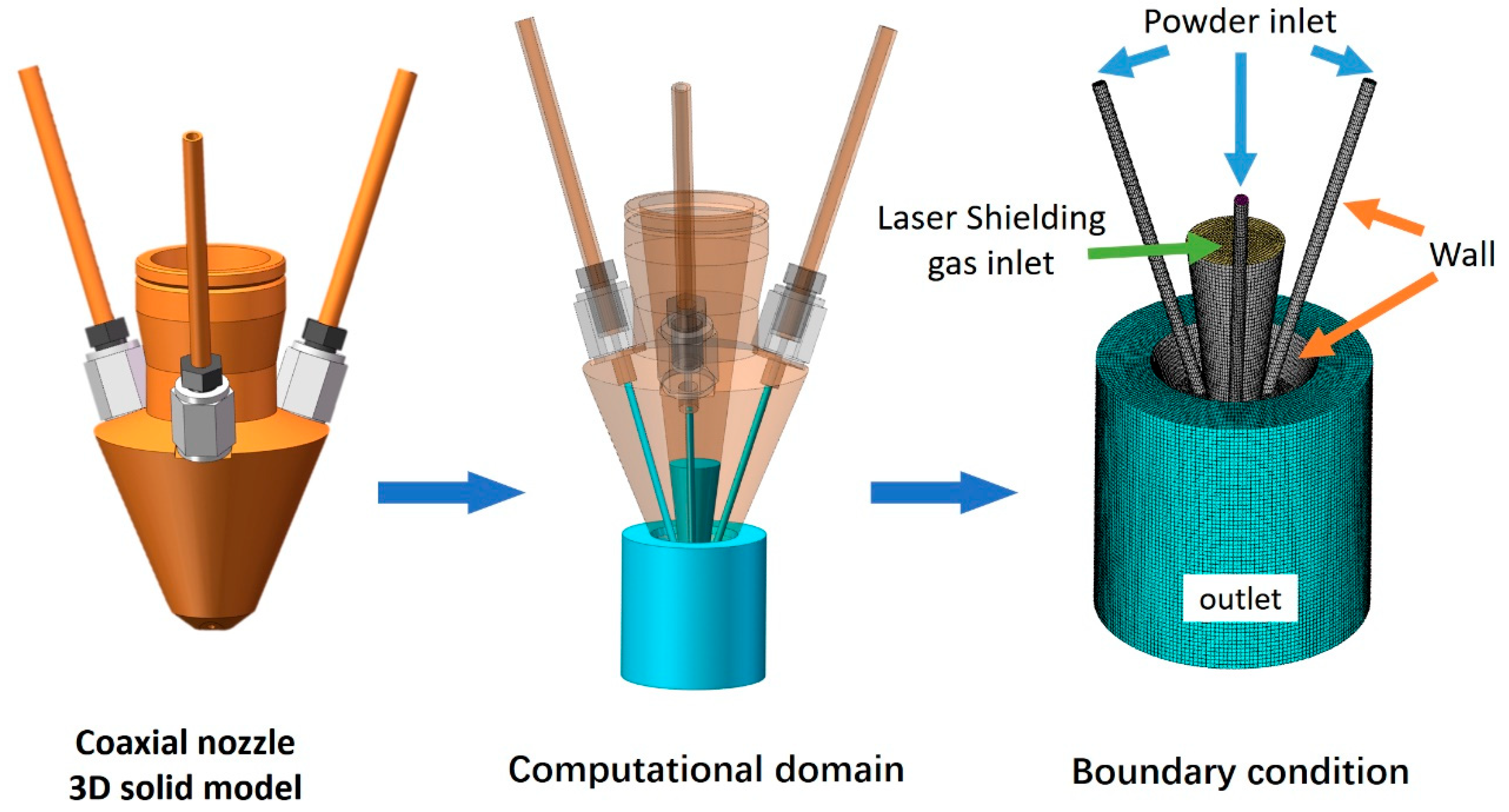
A realistic coaxial discrete three beam nozzle was used as the research object. After modeling the nozzle, the powder passage, a part of the inner laser shielding gas passage, inside nozzle, and a reasonable range of powder flow area outside the nozzle were taken as the calculation domain. The boundary conditions of the calculation domain were set according to a realistic situation. The modeling process is shown in Figure 1. The boundary condition was set as follows: the inlet type is the velocity inlet, the outlet type is the pressure outlet, and the remaining parameters concern the wall, with an elasticity coefficient of 0.99. A set of standard parameters were set, shown in Table 2.
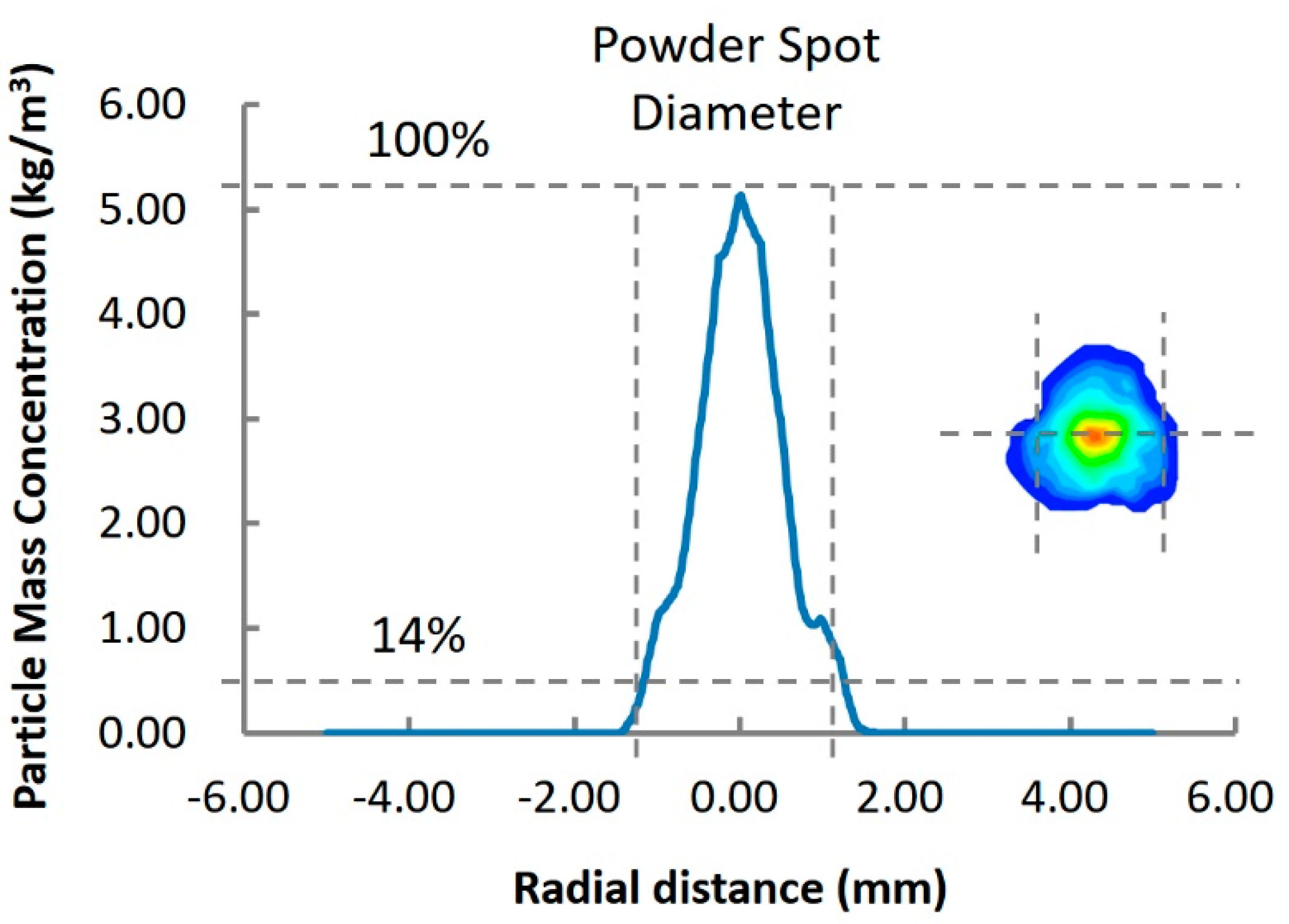
The diameter of the powder spot was calculated by taking 14% of the peak concentration of the powder spot as the boundary. The calculation process of powder stream focus spot diameter under standard parameters is shown in Figure 2 as an example. This definition is used to ensure quantifiable contrast of simulation results.
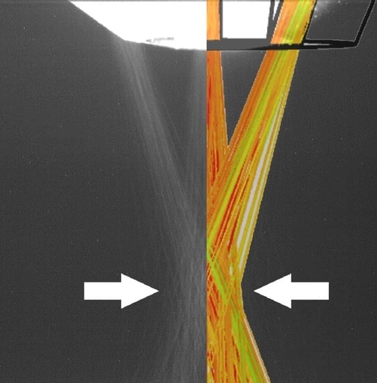
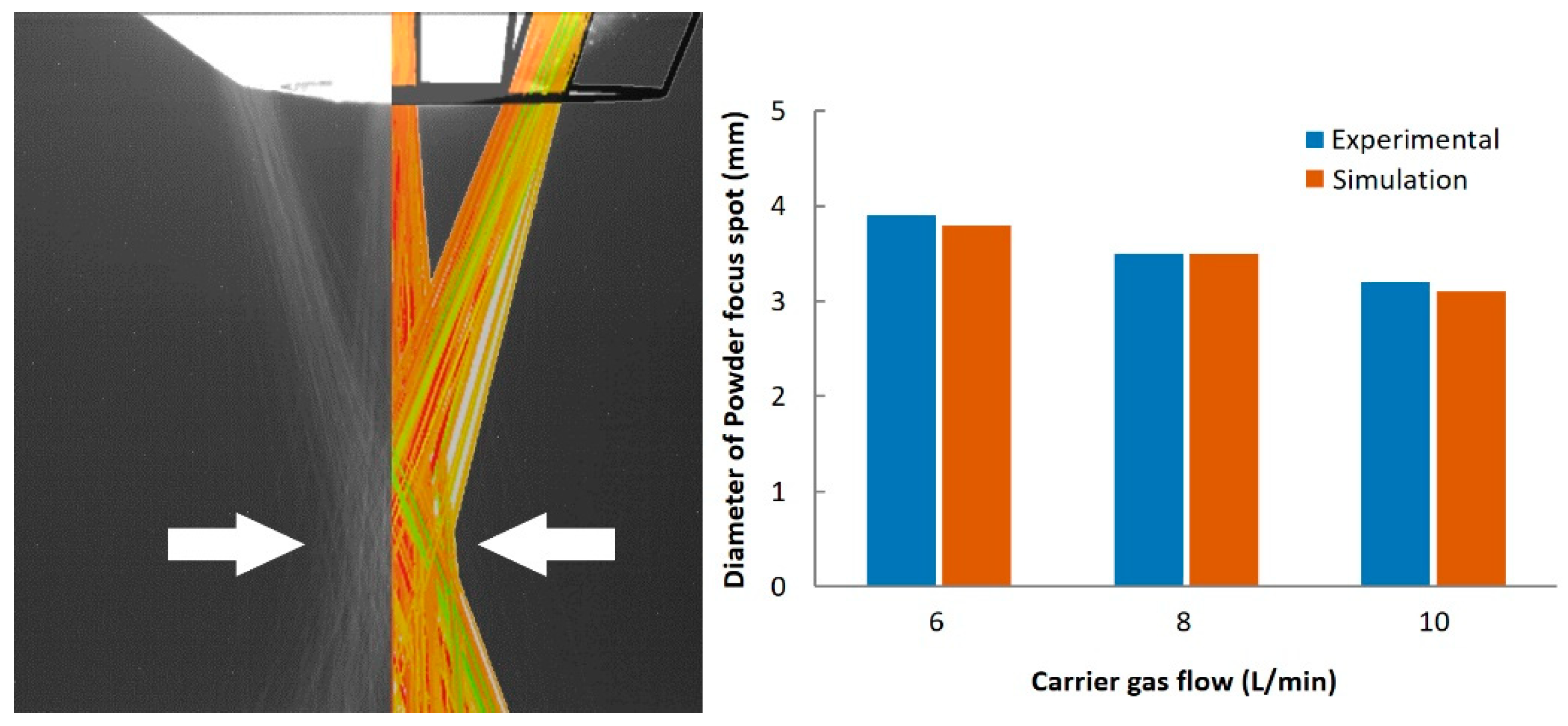
With a CCD camera, the powder stream convergence characteristics under given nozzle and gas settings were monitored. Figure 3 presents the trajectory of Ti6Al4V powder streams during the flying procedure out of the nozzle tip produced by CFD modeling and CCD photography (50 frames per second) respectively. By utilizing the same definition method, the diameter of the photographed powder spot under different parameters were measured and compared with the simulation results. It was found that the calculated trajectories are in good agreement with the experimental observations, and they provide a good insight into the process phenomena.
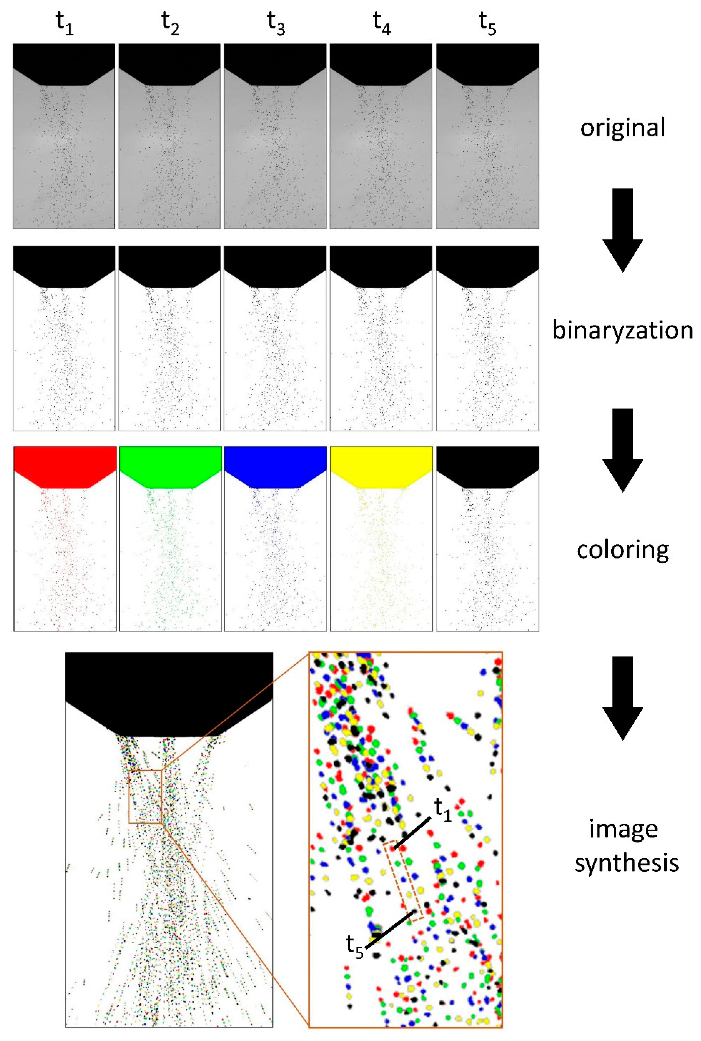
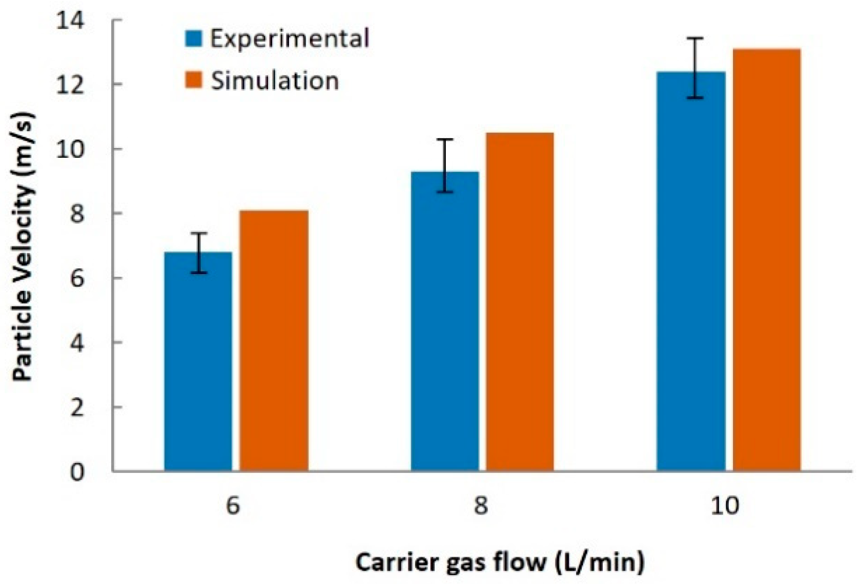
In order to obtain the velocity of the particle, the powder stream was photographed with a high-speed camera of 10,000 frames per second. As shown in Figure 4, t1 to t5 are five images of the powder stream with a framerate of 10−4 s. Through binarization and colors of the five photos, they are combined into one image. By measuring the distance between the positions of the particles at different times in the composite image, the velocity of the particles can be measured. In this method, the measured particle velocities under different parameters are compared with the simulated results in Figure 5. It also shows that the simulation results are in good agreement with the experimental results. Furthermore, since the image can only obtain two-dimensional information, the comparison of velocity is only conducted by two-dimensional vectors, which is less than the maximum particle velocity of the numerical simulation results.
3. Result and Discussion
3.1. Collision between Powders and Passage Inner Wall
In Pan et al. (2006) and Zekovic et al. (2007) studies, the powder stream inlet direction was set parallel to the passage, for which the powder focus obtained has good convergence and uniformity. Nevertheless, analysis of the powder focus size is rarely involved in these studies because changes in powder or gas parameters would not have any effect on the convergence characteristics of the powder stream.
In the realistic process, the collision between powder and passage wall is inevitable, and this collision is the reason that powder flow diverges at the nozzle outlet and finally forms different powder spot sizes.
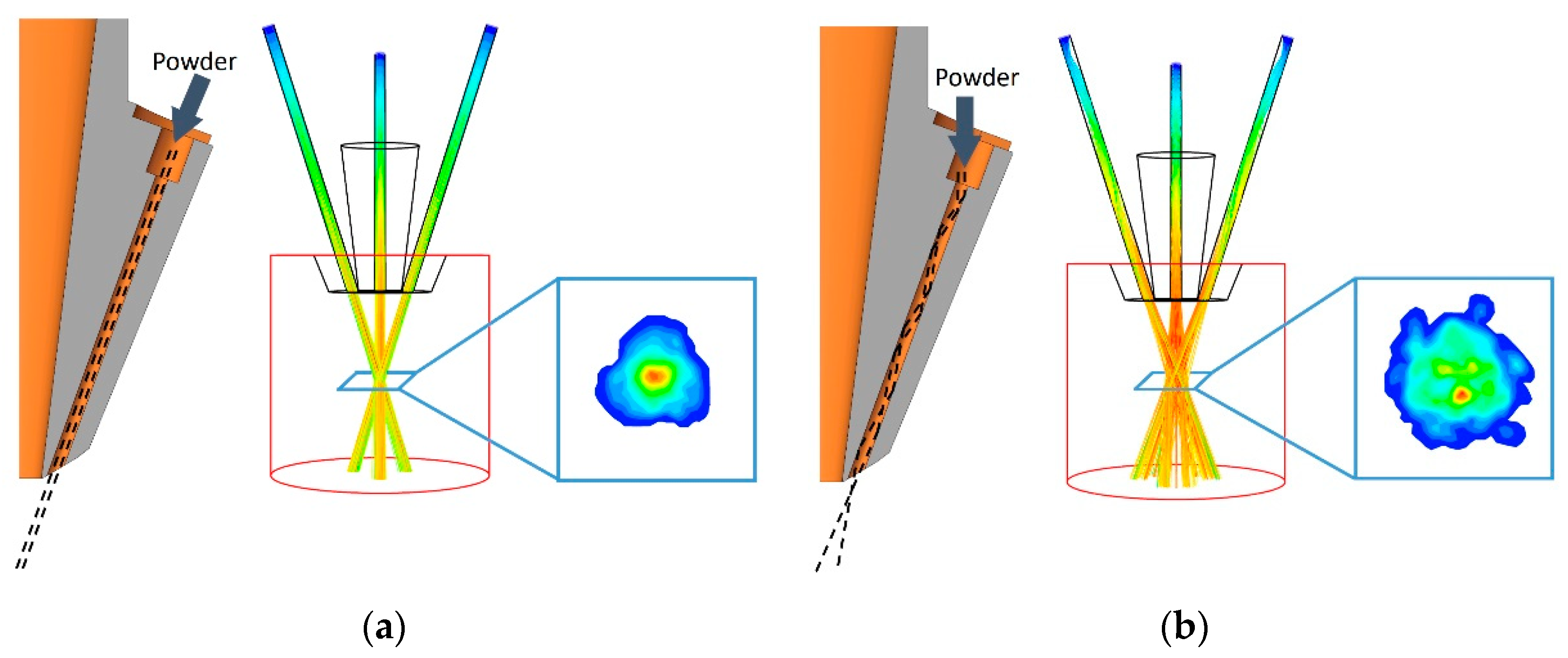
As shown in Figure 6a, when the powder is incident parallel to the passage, the powder is only dragged by the gas flow moving along the passage, resulting in the same diameter of the powder flow at the nozzle outlet as at the incident diameter. An ideal Gaussian distribution can be formed at the focal point of the powder stream. The diameter of the spot can even be calculated by simple geometric formula, but this result is obviously not convincing.
The realistic process is that the powder enters at random angles and velocity, causing multiple reflections of the powder against the wall of the passage, and moving forward to the nozzle outlet driven by the gas flow. After the last collision, it will shoot out at a specific angle in the passage direction. Furthermore, a powder spot with divergence and randomness appears at the focus plane.
Figure 6b is a simplified process of random incidence of powder stream. It is assumed that all powders enter the passage in the vertical direction. It can be found that the powder stream diverges at the nozzle outlet, and a random powder spot with Gaussian distribution pattern is formed.
3.2. The Influence of Nozzle Structure Parameters
3.2.1. Passage Length
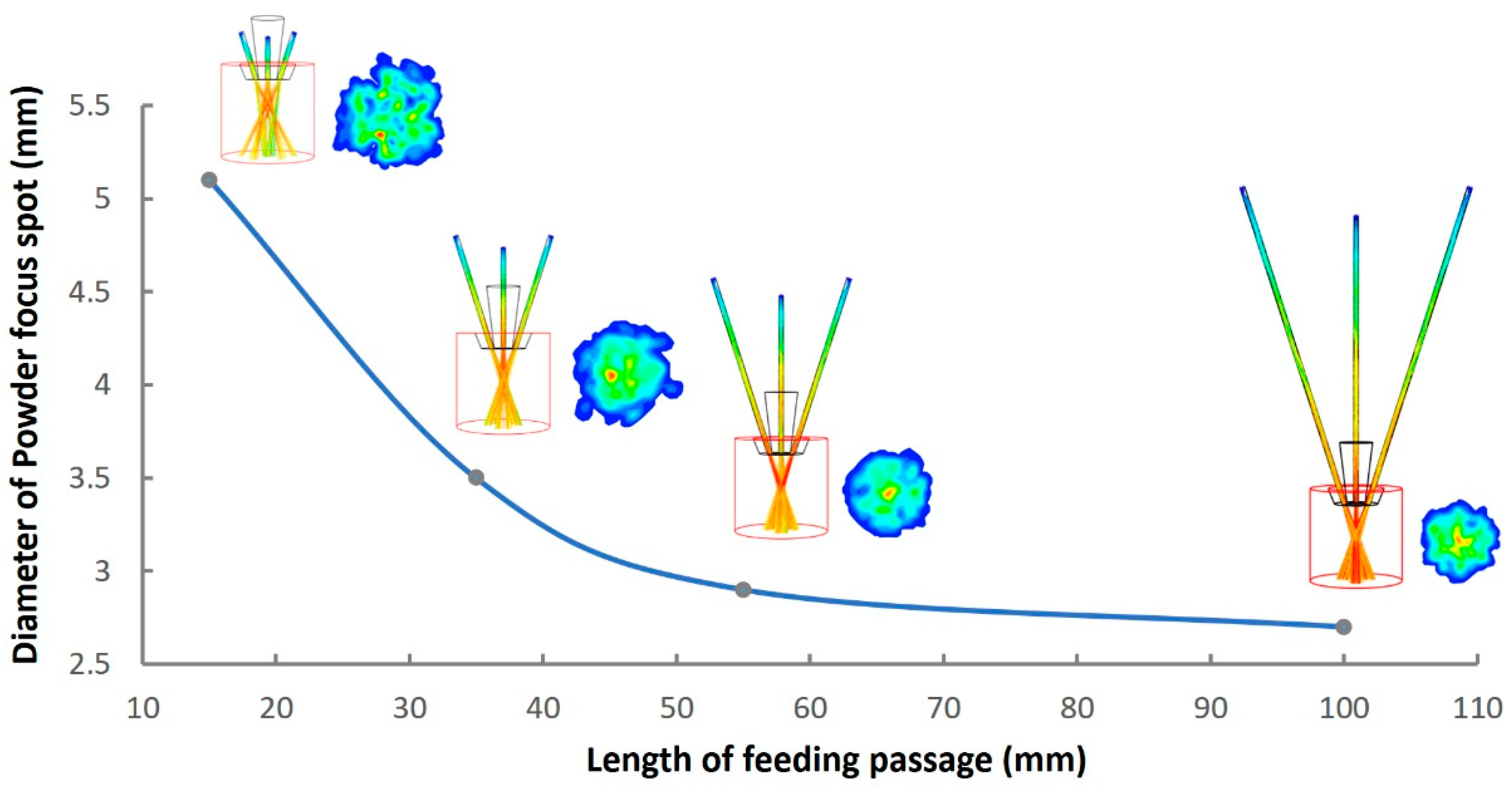
Through the simulation of nozzle structure from 15 mm to 100 mm in passage length, it is found that the diameter of the powder focus spot can be reduced from 5.1 mm to 2.6 mm, accompanied by a more uniform powder concentration distribution. Nevertheless, this process presents a logarithmic curve change, that is to say that, excessively increasing the passage length will not lead to a more obvious decrease in the size of powder spots, but the size of powder spots will approach a certain limit value, as shown in the curve in Figure 7.
3.2.2. Passage Diameter
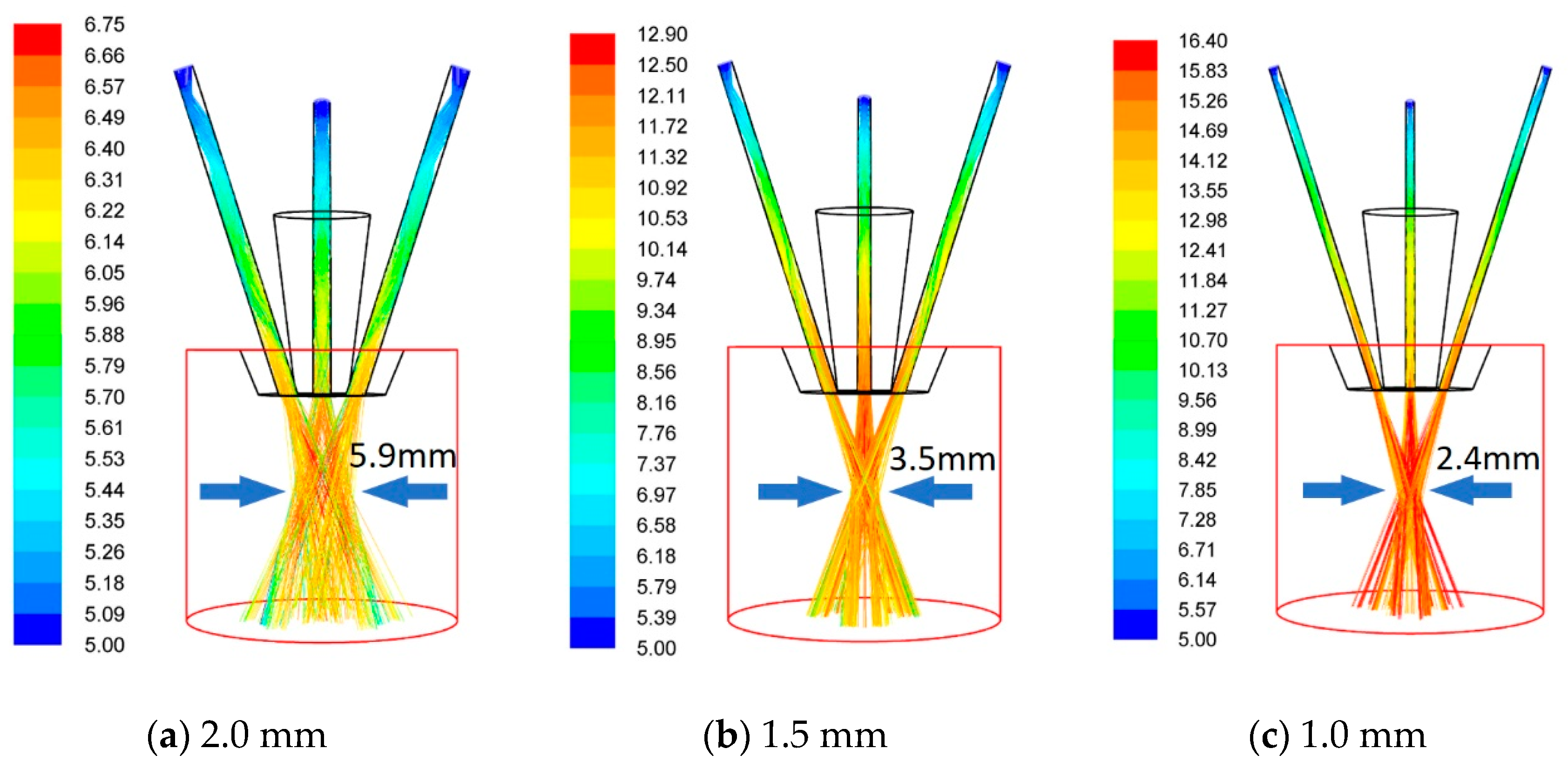
Changing the diameter of the passage is an effective way to reduce the size of the powder spot. As Shown in Figure 8, by simulating the three passage diameters of 2.0 mm, 1.5 mm and 1.0 mm, it can be found that the diameter of the powder spot decreases from 5.9 mm to 2.4 mm with other parameters constant. Meanwhile, the maximum velocity of powder also increased from 6.75 m/s to 16.4 m/s, and the corresponding powder carrier gas flow rate was 8 L/min.
In the case of constant gas flow, a reduction in the diameter of the passage results in an increase in the velocity of the inlet gas. Due to the square ratio of diameter to area, the gas flow inlet velocity with a diameter of 1.0 mm is 4 times that of the inlet with a diameter of 2.0 mm, which will have a huge impact on the flow state of the powder. Compared with increasing the passage length, decreasing the passage diameter has a more significant effect on improving the powder convergence. However, reducing the diameter in the actual process will increase the risk of powder blocking in the passage, which cannot be considered and showed in the numerical simulation result. Meanwhile, it is more difficult to fabricate the small passage, so it is necessary to find a balance between diameter and length.
3.2.3. Passage Shrinkage
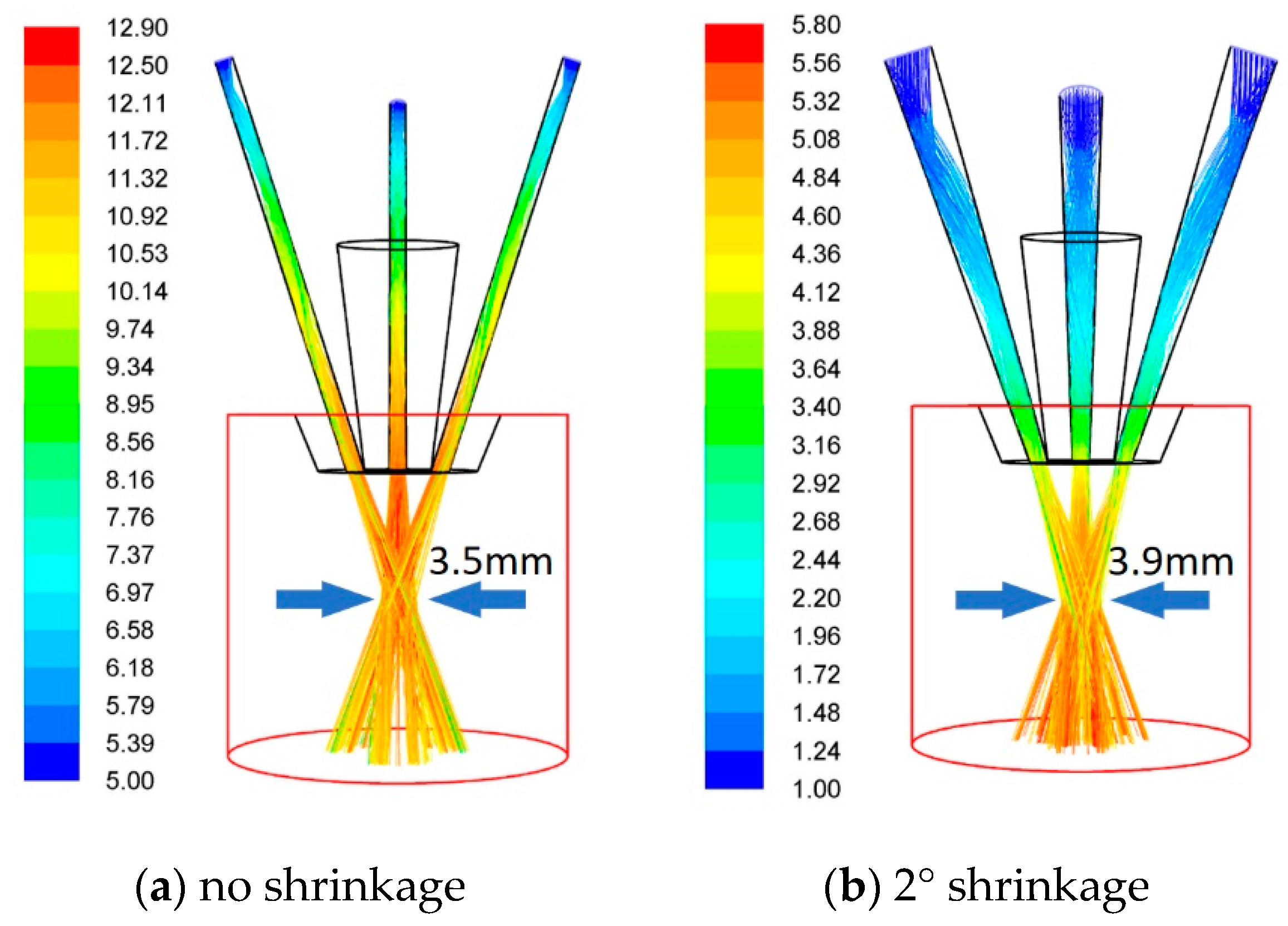
In Arrizubiteta et al. (2014), the passage of coaxial nozzles contains a shrinkage structure to improve the convergence of powder stream, but there is a lack of discussion on the rationality of such structure design. It can be seen from the results of Figure 9 that the shrinking structure does not have a beneficial effect on the powder stream. The maximum velocity of the powder decreased from 12.9 m/s without shrinkage to 5.8 m/s at 2° contraction, and the diameter of the powder spot increased from 3.5 mm to 3.9 mm. Under the condition of the same outlet diameter, the increase of inlet diameter (with taper) will lead to the increase of powder convergence spots.
3.3. The Influence of Process Parameters
3.3.1. Particle Size Distribution
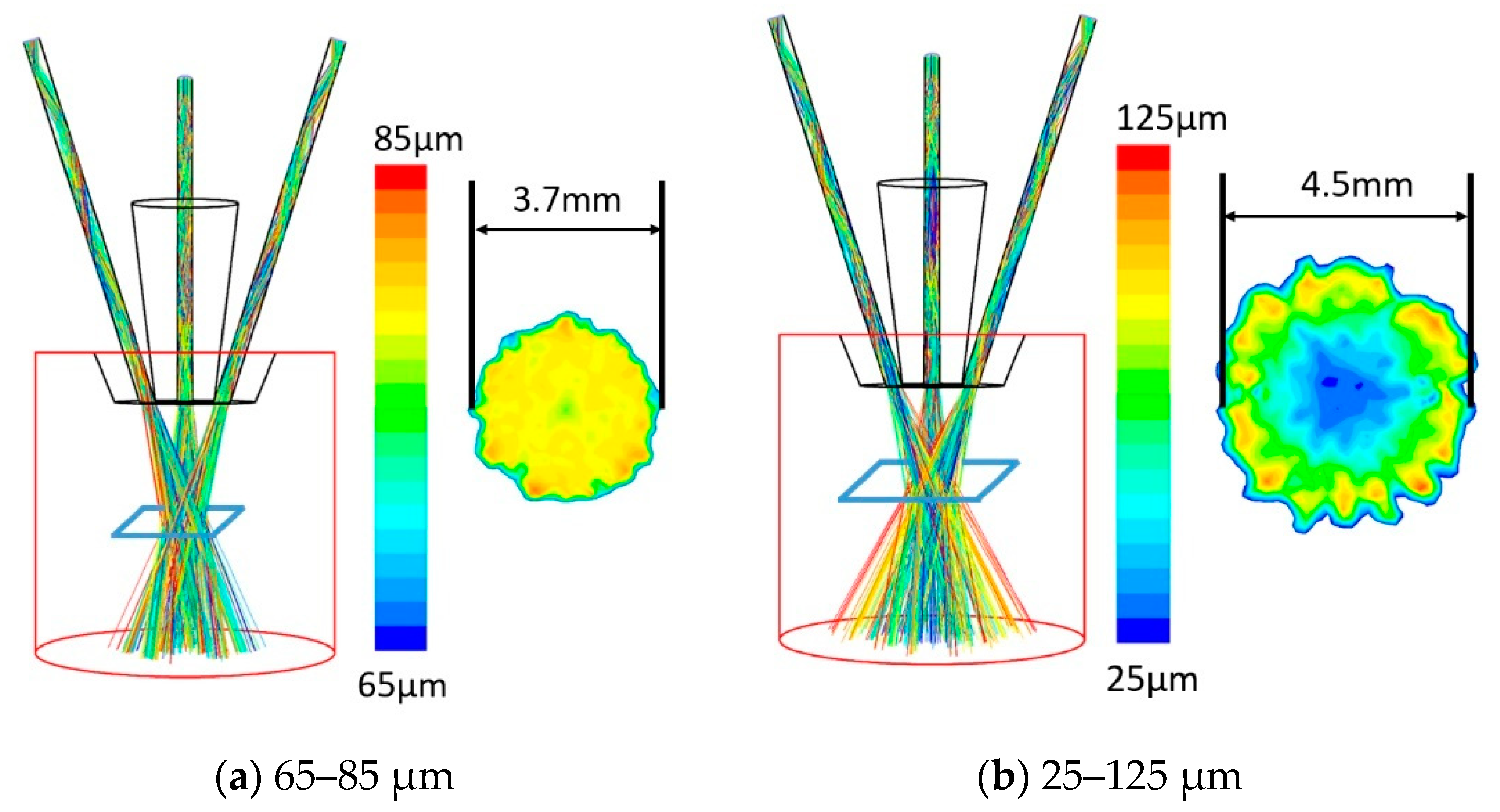
In reality, the particle size of the powder must exist within a range. The distribution of particle size can be represented by the Rosin-Rammler model, which has been widely used in similar research. According to the analysis of 65–85 μm and 25–125 μm powder streams, which are both normally distributed and have a median of 75 μm. As can be seen from Figure 10, the focused spot of powder stream is smaller with uniform particle size. In addition, when the particle size distribution range is large, the powder with smaller particle sizes are concentrated in the center of the spot, unlike that of larger particles. The reasoning is that the powder with a smaller particle size has a larger specific surface area and is more strongly dragged by the gas, so it is more likely to be confined in the central area of the gas flow.
This phenomenon can be used for reference by the two-phase mixed powder stream. Because the diameter of powder spots is usually larger than the width of the molten pool, the uneven distribution of powder spots will affect the proportion of powder falling into the molten pool. On the other hand, powder with a small particle size can absorb laser energy more easily due to its larger specific surface area, which will affect the regulation of LMD process parameters.
3.3.2. Inner Laser Shielding Gas
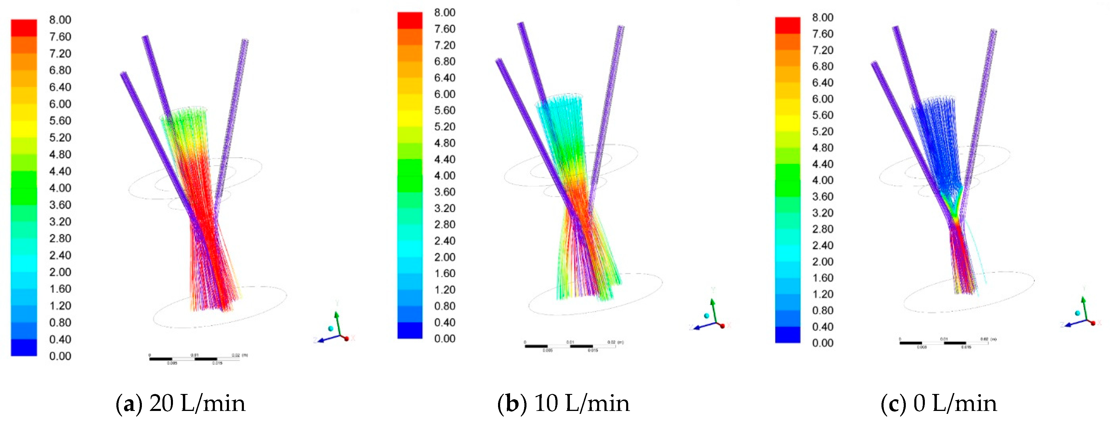
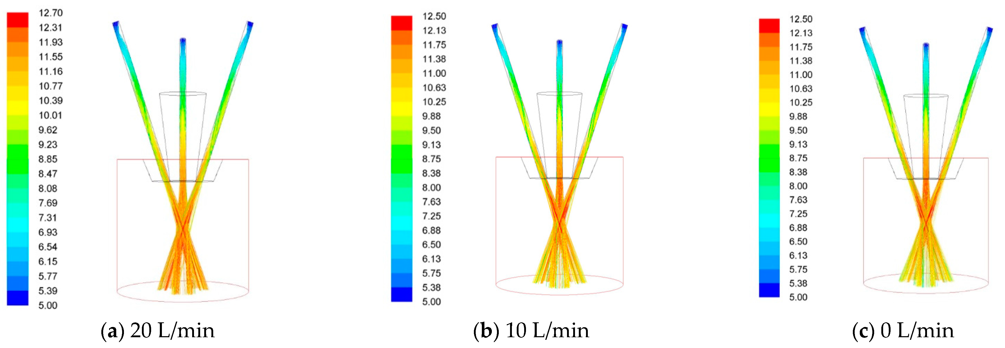
The inner ring laser shielding gas is a non-negligible parameter. In the previous study, for coaxial continuous laser cladding nozzles, the increase of inner ring laser shielding gas will directly affect the convergence height of powder flow. However, for coaxial discrete nozzles, it can be seen from the results in Figure 11 that shielding gas of different rates will flow out through the gap of the powder stream passages, and the impact on the converging position of the powder flow will be greatly reduced from the results in Figure 12.
In the simulation results, the diameter and height of the powder spots were almost unchanged. Therefore, for coaxial discrete nozzles this parameter can be adjusted within a wide range.
3.4. The Principle of Powder Spot Size Control
Efficient LMD process requires the deposition width of more than 5 mm, but for the precision blade manufacturing or repair it should be less than 2 mm. Thus, the size of the powder spot should be well matched with the size of laser spot and molten pool for different deposition widths, so as to ensure the quality of deposition and the utilization rate of materials, as shown in Figure 13. In this section, the divergence mechanism is studied based on the demand for the control of powder spot size.
The powder stream is composed of a large number of particles. In order to control the divergence of the powder flow and the size of the powder spots, the means to reduce the divergence of each particle should be the focus of research.
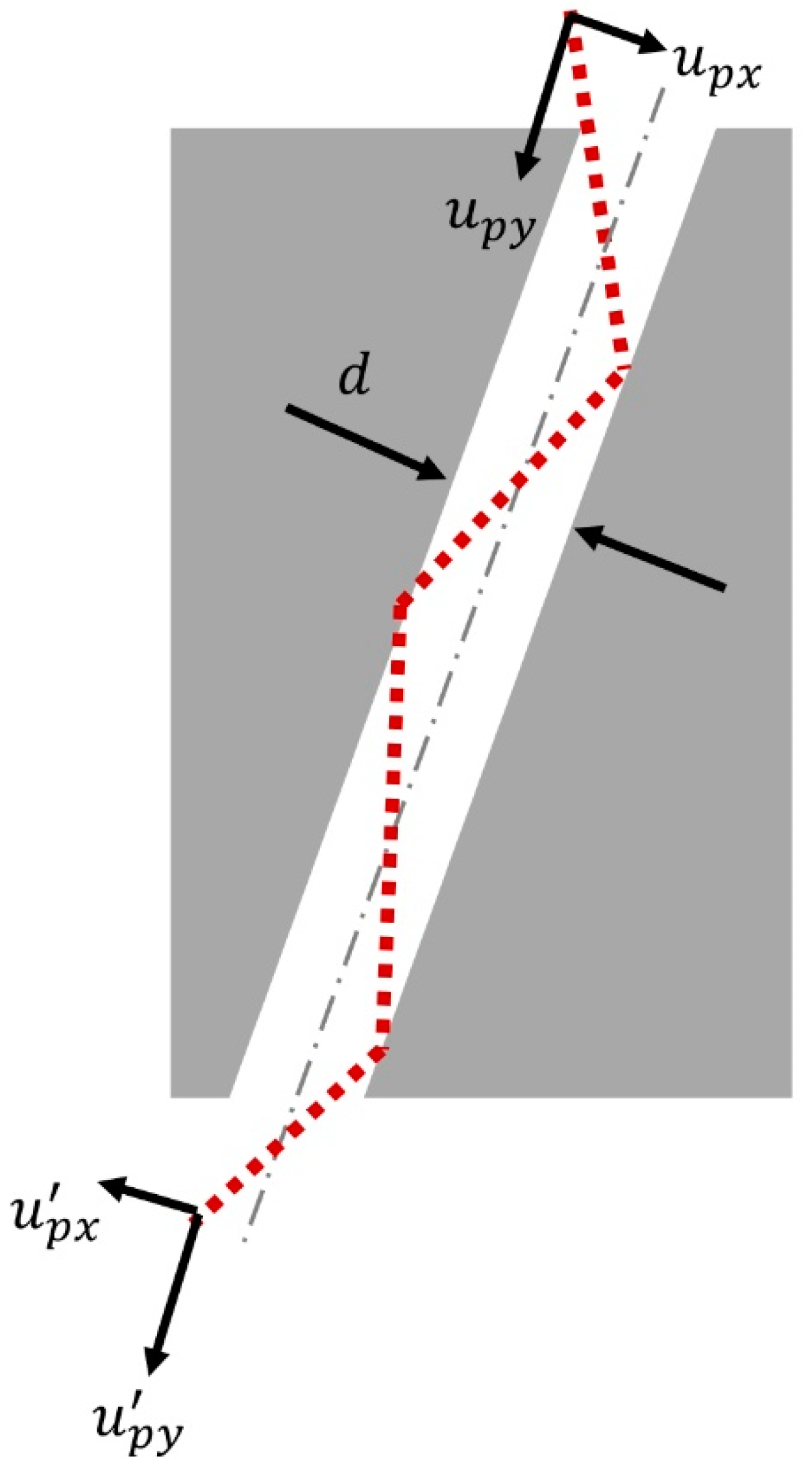
In the process of the particle passing through the passage, the initial velocity of the particle is defined as , and the velocity at the time of injection is . Taking the direction parallel to the passage as the Y-axis and the to the passage as the X-axis, these two velocities can be divided into , , and respectively, as shown in Figure 13. The divergence angle of the powder is determined by the vector as it is ejected. In order to reduce the divergence angle, the fundamental rule is to increase and decrease .
The process from to , is mainly affected by the drag force of gas flow in the passage. Equation (5) is obtained from Equations (1) and (2).
where the gas velocity can be seen as proportional to the area of the passage,
where d is the diameter of the passage as shown in Figure 14.
It can be seen from Equations (5) and (6) that particle size dp and passage diameter d have a quadratic effect on , and the density of powder has a proportional effect on it. This indicates that smaller powder spot diameters can be obtained by selecting a powder with a smaller particle size and density and the nozzle with finer diameter passages.
Since the particle’s motion in the passage is continuously accelerated by the gas flow, and it is easy to understand, the maximum value of the particle’s velocity is the gas velocity. Therefore, longer passage can make the larger, thus making the powder spots smaller. However, due to the limitation of the maximum velocity of the particles, the speed of the powder spot decreases gradually down to a minimum value with the increase of passage length, which has been proved in the previous section.
In the process from to , generally the inelastic collision between powder and the inner wall of the passage will have an impact on it, which has been analyzed in some studies [4], and better powder convergence can be obtained by reducing the elastic recovery coefficient. However, due to the near wall effect of the channel, the gas velocity near the wall is slower. In the inelastic collision process, particles will stay near the wall for a longer time, resulting in smaller increment. Therefore, even if the material with a small recovery coefficient is selected, the size of the powder spot will not be significantly improved in practice. This process cannot be considered in numerical simulation, and the results are often contrary to the experimental result. On the other hand, it can reduce and increase at the time of incident through various ways, so that a powder flow with good convergence characteristics can also be obtained.
In a realistic process, the above-mentioned parameters are usually divided into material parameters, nozzle structure parameters, and powder and processing parameters. A reasonable parametric design process should include the following steps:
(1) specify manufacturing requirements and select suitable materials;
(2) choose a nozzle with proper structure according to the required deposition width;
(3) choose appropriate particle size interval according to the required deposition width, and adjust powder carrier gas and shielding gas to reach the designed powder flow size.
After the above parameters are selected, a good LMD process can begin normally.
4. Conclusions
The 3D numerical model was developed to predict the powder stream structure in different parameters with a main purpose of evaluating the convergence and concentration distribution for the coaxial laser metal deposition nozzle. Based on high-speed imaging and CCD technology, the powder stream flying procedure was captured to verify the calculated results. Some findings are summarized as follows:
(1) The collision of the powder with the inner wall of the passage is the reason for the powder stream divergence at the nozzle outlet.
(2) By increasing the length and decreasing the diameter of the passage, smaller powder spots can be obtained. Shrinkage structure of the passage does not contribute to increased concentration of powder streams.
(3) The gas flow has a stronger drag force on particles of small size, so when the particle size distribution is wide, the small particles will be obviously concentrated in the center of the focal powder spot, and the periphery is distributed with large powder.
5. Outlook
In future research, the interaction between powder, laser and molten pool will be explored, so as to theoretically study the influence of powder stream on the molten pool and the laser cladding process. Some research has been carried out, but it has not yet been systematically analyzed, and so the relevant results were not outlined in this article.
Author Contributions
Conceptualization, L.L.; methodology, L.L. and W.T.; validation, L.L and W.T.; formal analysis, Y.H.; software, C.Z.; investigation, L.L. and W.T.; data curation, Y.H. and C.Z.; writing—original draft preparation, Y.H.; writing—review and editing, Y.H.; visualization, L.L.; supervision, L.L.; project administration, L.L. All authors have read and agreed to the published version of the manuscript.
Funding
This research received no external funding. This research did not receive any specific grant from funding agencies in the public, commercial, or not-for-profit sectors.
Institutional Review Board Statement
Not applicable.
Informed Consent Statement
Not applicable.
Data Availability Statement
Data available on request due to restrictions e.g., privacy or ethical. The data presented in this study are available on request from the corresponding author. The data are not publicly available due to the structural model containing unpublished patents.
Conflicts of Interest
The authors declare no conflict of interest.
References
- Tamanna, N.; Crouch, R.; Naher, S. Progress in numerical simulation of the laser cladding process. Opt. Lasers Eng. 2019, 122, 151–163. [Google Scholar] [CrossRef]
- Lin, J. Numerical simulation of the focused powder streams in coaxial laser cladding. J. Mater. Process. Technol. 2000, 105, 17–23. [Google Scholar] [CrossRef]
- Pinkerton, A.J.; Li, L. Modelling powder concentration distribution from a coaxial deposition nozzle for laser-based rapid tooling. J. Manuf. Sci. Eng. 2004, 126, 33–41. [Google Scholar] [CrossRef]
- Pan, H.; Liou, F. Numerical simulation of metallic powder flow in a coaxial nozzle for the laser aided deposition process. J. Mater. Process. Technol. 2005, 168, 230–244. [Google Scholar] [CrossRef]
- Pan, H.; Sparks, T.; Thakar, Y.D.; Liou, F. The investigation of gravity-driven metal powder flow in coaxial nozzle for laser-aided direct metal deposition process. J. Manuf. Sci. Eng. 2006, 128, 541–553. [Google Scholar] [CrossRef]
- Zekovic, S.; Dwivedi, R.; Kovacevic, R. Numerical simulation and experimental investigation of gas–powder flow from radially symmetrical nozzles in laser-based direct metal deposition. Int. J. Mach. Tools Manuf. 2007, 47, 112–123. [Google Scholar] [CrossRef]
- Wen, S.Y.; Shin, Y.C.; Murthy, J.Y.; Sojka, P.E. Modeling of coaxial powder flow for the laser direct deposition process. Int. J. Heat Mass Transf. 2009, 52, 5867–5877. [Google Scholar] [CrossRef]
- Tabernero, I.; Lamikiz, A.; Ukar, E.; De Lacalle, L.L.; Angulo, C.; Urbikain, G. Numerical simulation and experimental validation of powder flux distribution in coaxial laser cladding. J. Mater. Process. Technol. 2010, 210, 2125–2134. [Google Scholar] [CrossRef]
- Zhu, G.; Li, D.; Zhang, A.; Tang, Y. Numerical simulation of metallic powder flow in a coaxial nozzle in laser direct metal deposition. Opt. Laser Technol. 2011, 43, 106–113. [Google Scholar] [CrossRef]
- Kovaleva, I.; Kovalev, O.; Zaitsev, A.; Smurov, I. Numerical simulation and comparison of powder jet profiles different types of coaxial nozzles in direct material deposition. Phys. Procedia 2013, 41, 870–872. [Google Scholar] [CrossRef] [Green Version]
- Smurov, I.; Doubenskaia, M.; Zaitsev, A. Complex analysis of laser cladding based on comprehensive optical diagnostics and numerical simulation. Phys. Procedia 2012, 39, 743–752. [Google Scholar] [CrossRef] [Green Version]
- Nie, P.; Ojo, O.A.; Li, Z. Modeling analysis of laser cladding of a nickel-based superalloy. Surf. Coat. Technol. 2014, 258, 1048–1059. [Google Scholar] [CrossRef]
- Arrizubieta, J.I.; Tabernero, I.; Ruiz, J.E.; Lamikiz, A.; Martínez, S.; Ukar, E. Continuous coaxial nozzle design for LMD based on numerical simulation. Phys. Procedia 2014, 56, 429–438. [Google Scholar] [CrossRef] [Green Version]
- Liu, Z.; Qi, H.; Jiang, L. Control of crystal orientation and continuous growth through inclination of coaxial nozzle in laser powder deposition of single-crystal superalloy. J. Mater. Process. Technol. 2016, 230, 177–186. [Google Scholar] [CrossRef]
- Zhang, B.; Coddet, C. Numerical study on the effect of pressure and nozzle dimension on particle distribution and velocity in laser cladding under vacuum base on CFD. J. Manuf. Process. 2016, 23, 54–60. [Google Scholar] [CrossRef]
- Koruba, P.; Wall, K.; Reiner, J. Influence of processing gases in laser cladding based on simulation analysis and experimental tests. Procedia CIRP 2018, 74, 719–723. [Google Scholar] [CrossRef]
- Ju, H.; Zhang, Z.J.; Lin, C.X.; Liu, Z.J. Design optimization and experimental study of coaxial powder-feeding nozzle in the laser cladding process. IOP Conf. Ser. Mater. Sci. Eng. 2019, 474, 012008. [Google Scholar] [CrossRef]
- Guo, S.R.; Yin, Q.Q.; Cui, L.J.; Xiao, L.L.; Cui, Y.H.; Zheng, B.; Cao, Y.L.; Zeng, W.Z. Simulation and experimental research based on carrier gas flow rate on the influence of four-channel coaxial nozzle flow field. Meas. Control 2020, 53, 9–10. [Google Scholar] [CrossRef]
- Morsi, S.A.; Alexander, A.J. An Investigation of Particle Trajectories in Two-Phase Flow Systems. J. Fluid Mech. 1972, 55, 193–208. [Google Scholar] [CrossRef]
Figure 1.
The establishment of computational domain and its boundary conditions.

Figure 2.
The definition of powder spot diameter.

Figure 3.
Comparison of simulation and experimental results of the powder spot diameter.

Figure 4.
Measurement of particle velocity by high-speed camera (10,000 frames per second).

Figure 5.
Comparison of simulation and experimental results of the particle velocity.

Figure 6.
Schematic of powder incident direction and concentration distribution of powder stream for coaxial discrete nozzle. (a) The powder is parallel to the passage; (b) the powder is tilt to the passage.
Figure 6.
Schematic of powder incident direction and concentration distribution of powder stream for coaxial discrete nozzle. (a) The powder is parallel to the passage; (b) the powder is tilt to the passage.

Figure 7.
Influence of passage length on powder focal spot diameter.

Figure 8.
The influence of different passage diameters on powder focus spot size. (a) 2.0 mm; (b) 1.5 mm; (c) 1.0 mm.
Figure 8.
The influence of different passage diameters on powder focus spot size. (a) 2.0 mm; (b) 1.5 mm; (c) 1.0 mm.

Figure 9.
Powder focus spot diameters with and without passage shrinkage. (a) no shrinkage; (b) 2° shrinkage.
Figure 9.
Powder focus spot diameters with and without passage shrinkage. (a) no shrinkage; (b) 2° shrinkage.

Figure 10.
Particle sizes distribution in powder stream for coaxial-discrete nozzle. (a) 65–85 μm; (b) 25–125 μm.
Figure 10.
Particle sizes distribution in powder stream for coaxial-discrete nozzle. (a) 65–85 μm; (b) 25–125 μm.

Figure 11.
Influence of inner shielding gas on carrier gas. (a) 20 L/min; (b) 10 L/min; (c) 0 L/min.
Figure 11.
Influence of inner shielding gas on carrier gas. (a) 20 L/min; (b) 10 L/min; (c) 0 L/min.

Figure 12.
Influence of inner shielding gas on powder stream. (a) 20 L/min; (b) 10 L/min; (c) 0 L/min.
Figure 12.
Influence of inner shielding gas on powder stream. (a) 20 L/min; (b) 10 L/min; (c) 0 L/min.

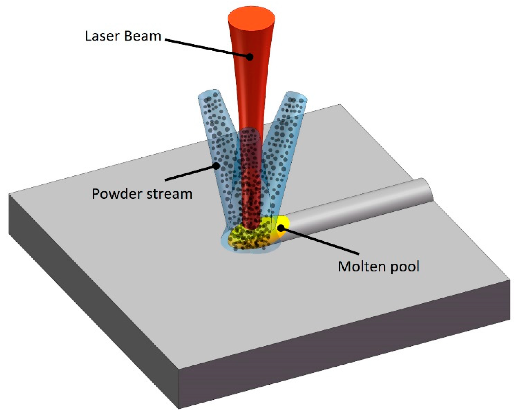
Figure 13.
Schematic of the interaction of powder with laser and molten pool in LMD process.

Figure 14.
Schematic of particle movement in the passage.

Table 2.
The standard parameters.
| Powder Material | Ti6Al4V |
| Powder Size | 75 μm, Spherical |
| Powder Flow Rate | 5 g/min |
| Particle Carrier Gas Flow Rate | 8 L/min |
| Inner Shielding Gas Flow Rate | 10 L/min |
Publisher’s Note: MDPI stays neutral with regard to jurisdictional claims in published maps and institutional affiliations. |
© 2021 by the authors. Licensee MDPI, Basel, Switzerland. This article is an open access article distributed under the terms and conditions of the Creative Commons Attribution (CC BY) license (http://creativecommons.org/licenses/by/4.0/).
Share and Cite
MDPI and ACS Style
Li, L.; Huang, Y.; Zou, C.; Tao, W. Numerical Study on Powder Stream Characteristics of Coaxial Laser Metal Deposition Nozzle. Crystals 2021, 11, 282. https://0-doi-org.brum.beds.ac.uk/10.3390/cryst11030282
AMA Style
Li L, Huang Y, Zou C, Tao W. Numerical Study on Powder Stream Characteristics of Coaxial Laser Metal Deposition Nozzle. Crystals. 2021; 11(3):282. https://0-doi-org.brum.beds.ac.uk/10.3390/cryst11030282
Chicago/Turabian StyleLi, Liqun, Yichen Huang, Chunyu Zou, and Wang Tao. 2021. "Numerical Study on Powder Stream Characteristics of Coaxial Laser Metal Deposition Nozzle" Crystals 11, no. 3: 282. https://0-doi-org.brum.beds.ac.uk/10.3390/cryst11030282
Note that from the first issue of 2016, this journal uses article numbers instead of page numbers. See further details here.