
Millimeter-Wave Reflector Based on a Ferroelectric Material with Electrical Beam Steering


Department of Physical Electronics and Technology, Saint-Petersburg Electrotechnical University “LETI”, 197376 Saint Petersburg, Russia
*
Author to whom correspondence should be addressed.
Crystals 2021, 11(6), 585; https://0-doi-org.brum.beds.ac.uk/10.3390/cryst11060585
Submission received: 16 March 2021
/
Revised: 11 May 2021
/
Accepted: 19 May 2021
/
Published: 22 May 2021
(This article belongs to the Special Issue Ferroelectrics Materials for Microwave Devices)
Abstract
:Millimeter waves are increasingly used in modern telecommunication systems for wireless data transmission. However, higher path loss, especially caused by non-line-of-sight scenarios, remains challenging. The design of an electrically controllable reflector for the millimeter-wave range is elaborated and presented in this manuscript. The reflector design was based on distributed ferroelectric ceramic elements and could be used in a frequency range up to 100 GHz. The issue of the ferroelectric reflector impedance matching was analyzed in detail. Two possible implementations of the reflector for indoor and outdoor communication systems were considered and simulated. The prototype of the proposed reflector for an operating frequency of 60 GHz was manufactured. Both simulation and measurement results demonstrated the beam steering by the proposed ferroelectric reflector.
1. Introduction
The interest in various wireless data services’ development for the millimeter-wave range has intensified in the few last years [1,2,3]. This follows from the continuously growing need for higher data rates and spectrum occupancy at lower frequencies. Currently, mm-wave communications can be considered the key for fifth-generation (5G) systems [1,2,3,4]. The outdoor implementations of the millimeter-wavelength wireless communication systems can be used in an indoor system. For example, the WiGig (IEEE 802.11ad) standard was elaborated for use in indoor environments mainly. It must complement Wi-Fi’s dual-band capability by enabling the use of a third, less congested frequency band at 60 GHz [5,6]. However, mainstreaming of millimeter-wave communication systems is limited by several drawbacks. One of them is high penetration∖propagation loss, especially in outdoor environments [7,8]. These adverse features seriously limit an mm-wave base station’s coverage area and lower the received power in the non-line-of-sight (NLOS) regions. The use of adaptive beamforming and increasing directional transmission can cancel out these weaknesses.
The use of a passive metallic reflector is the simplest way to improve mm-wave propagation in NLOS areas [9,10]. This solution is attractive due to the large life span and low cost. Passive metallic reflectors have been used in the past for microwave links for long-distance communications (such as satellite communications) and point-to-point microwave links. However, the passive reflectors’ main drawback is the dependence of output radiation on source antenna orientation. In other words, rearranging the antenna radiation pattern without mechanical steering is not allowed. However, mechanical control systems have drawbacks such as a limit in operation speed and the need to find a trade-off among controlling accuracy, reliability, and complexity for every system application.
Another way to provide the variation of the reflected signal direction is the control of the phase and/or amplitude of the reflection coefficient along the reflector surface. The most common name for this type of device is a reflectarray. It can be based on partially reflecting surfaces [11], frequency-selective surfaces [12,13], and metasurfaces with integrated tunable elements [14,15,16]. However, the operating frequencies of such devices currently are limited to the Ku-band. This restriction arises from the subwavelength sizes of unit cells comprising the metasurface. In combination with the electrically lumped nonlinear elements that need to provide the control, the fabrication technology is the main bottleneck to provide higher operating frequencies for such devices.
This manuscript proposed a reflector design based on ferroelectric (FE) materials for the millimeter-wavelength range. The proposed ferroelectric reflector device allows electrically controlling the deflection of the reflected wave to achieve the optimal direction of data transmission. The control of the reflected wave direction is based on the variation of the phase value of an electromagnetic wave propagated through the FE layer. The absence of lumped elements in the reflector design makes it promising for use in the millimeter-wavelength range. Its operating frequency limit is up to 100 GHz, where ferroelectric permittivity dispersion starts to be observed.
2. Materials and Methods
2.1. Principle of the Ferroelectric Reflector’s Operation
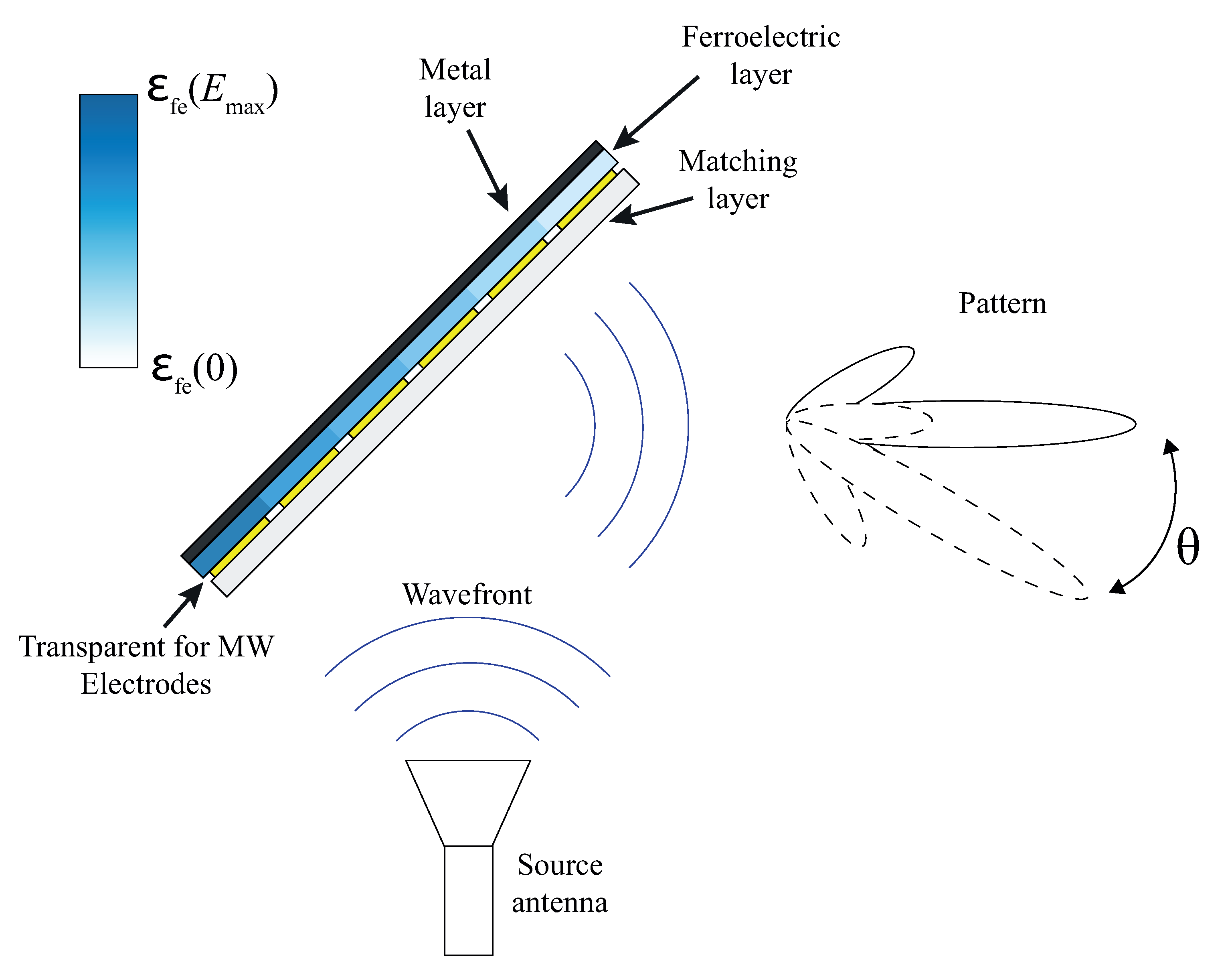
The proposed reflector design is schematically presented in Figure 1. It is a flat multilayer structure consisting of metal, ferroelectric, and linear dielectric layers. The proposed device’s principle of operation was based on a controllable variation of the electromagnetic-wave phase reflected from the metal surface.
The control of the wave phase value was performed by changing the dielectric constant of the FE layer localized on the metal surface. It is well known that the FE permittivity value can be varied by the application of an electric field E. Thus, a different phase distribution of the reflected wavefront can be formed by the variation of along the FE layer due to the application of an electric field. To provide the deflection of the reflected wave, one should provide a linearly changing FE permittivity value from its maximum value () to its minimum value () along the reflector aperture, as presented in Figure 1. The value of the deflection angle depends on this difference, and thus, it is more convenient to use the tunability factor (K) for estimations. The K-factor is a numerical characteristic of FE nonlinearity and is defined as:
The obtained angle of deflection can be estimated as:
where —the angle of incidence; —FE layer thickness; L—reflector aperture size. For the detailed derivation of this expression, see Appendix A.
To provide the required spatial distribution of FE permittivity along the reflector aperture, one should apply the control electric field to the FE layer. Note that such an electrode layer should not insert high loss and minimize the FE plate heating caused by the electric current (Joule heating). According to these requirements, it is reasonable to use electrodes that are transparent to microwave radiation (ETM) based on highly resistive thin-film materials. The topology of the ETM is presented as discrete sections that are electrically isolated from each other. Thus, the electric control voltage can be applied to each discrete section separately, while the metal layer (used for the wave reflection) provides a common ground electrode for each section. As example, in Figure 1, the reflector schematic with six ETMs is presented. Since the ETM topology is discrete, the spatial distribution of along the reflector aperture is discrete as well. This leads to the discretization of the deflected wavefront, and thus, the quality of the reflector radiation pattern directly depends on the ETMs’ sizes. To provide less distortion of the reflector radiation pattern, the ETMs’ sizes must be less than half of the operating wavelength [17].
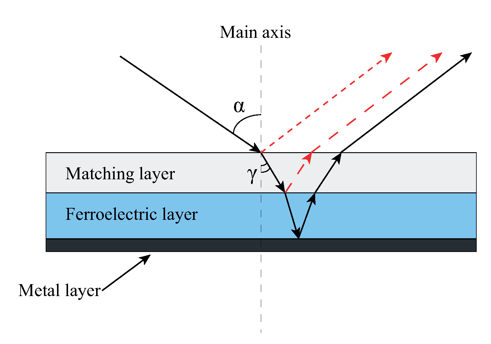
The typical value of FE ceramic permittivity is higher than 100. Therefore, matching the wave impedances is necessary due to the high value of in contrast to air. For this purpose, a matching layer from the linear dielectric material can be used (see Figure 1). Figure 2 shows the schematic of the reflected waves from the different reflector interfaces in the proposed reflector design. The red arrows represent undesired reflected waves; the ferroelectric plate cannot control these waves’ propagation directions. Thus, one can conclude that the power carried by such waves should be minimized to avoid the degradation of the reflector radiation pattern.
2.2. Materials
To achieve the optimal parameters of the proposed reflector design (in terms of beam deflection angle and impedance matching), the FE material with a high K value and a relatively low with low insertion loss should be used. The combination of these parameters is a criterion for choosing an FE material. To provide the beam-deflecting regime, the ferroelectric layer with a thickness of several wavelengths should be used. Thereby, the ferroelectric ceramic plates are more preferable for manufacturing the proposed mm-wavelength range reflector rather than thin or thick ferroelectric films.
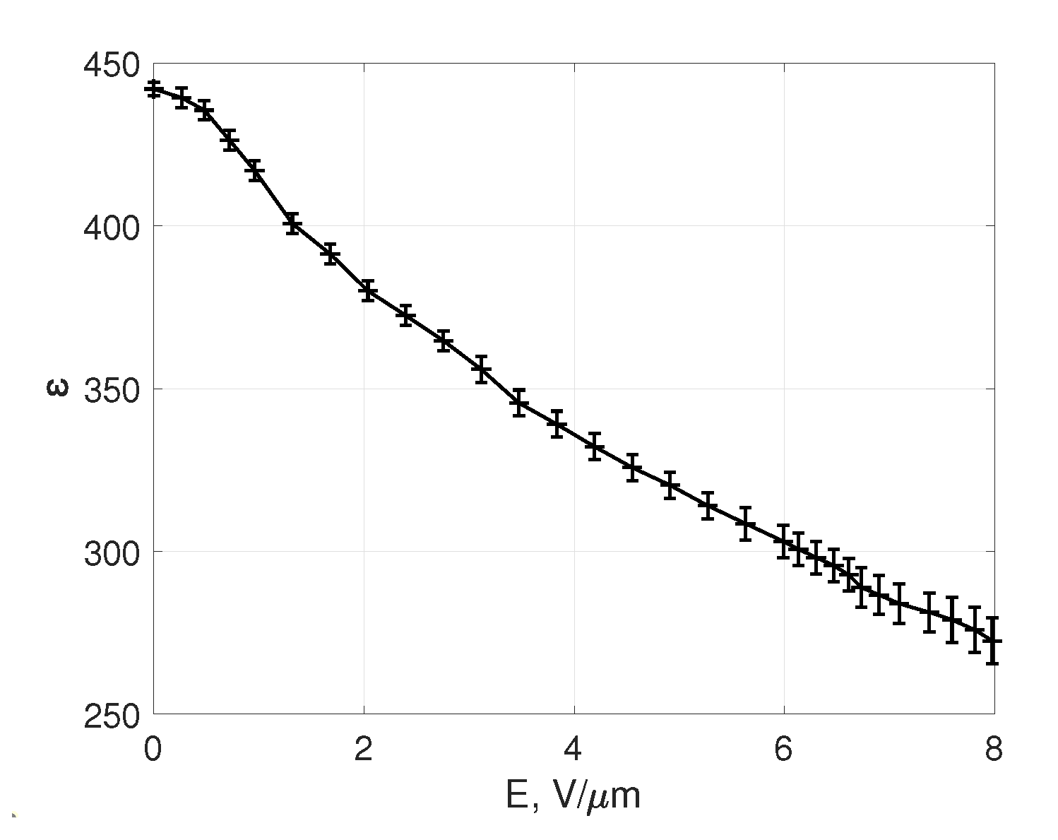
The ferroelectric ceramic based on a solid solution of barium-strontium titanate (BSTO) was used to investigate the potential of the proposed reflector design. The nonlinear characteristic of the BSTO ceramic samples was experimentally obtained and used during the electromagnetic simulations. Furthermore, this BSTO ceramic was used to manufacture the reflector prototype. The ferroelectric ceramic used to manufacture the prototype was produced by Ceramics Co. Ltd. (Saint Petersburg, Russia). It consisted of a mixture of previously synthesized BaTiO and SrTiO powders (in a proportion of 55/45) and 40 wt.% linear dielectric materials (MgTiO, MgO). The density of the ceramic was 5.1 g/cm; the dielectric constant was 440; and the tunability factor K = 1.8 at 10 V/mm. The dimensions of the ferroelectric ceramic plates were 48 × 60 × 1 mm. To determine the accurate permittivity value of the BSTO ceramic, parallel-plate capacitors were produced on its base. The capacitors’ electrodes were produced by the deposition of a copper film on opposite sides of the BSTO ceramic. The area of the capacitors was 5 × 5 mm. The RLC-meter (GW Instek LCR-8101G) with an operating frequency of 1 MHz was used for the measurement procedure. The experimental results of the measured permittivity values versus the electric field are presented in Figure 3. Since the ferroelectric material used demonstrated a relatively low permittivity (with respect to other ferroelectric materials) because of the high content of linear dopants, one should expect a negligible frequency dispersion of the permittivity [18]. The additional measurements of the ferroelectric permittivity at 60 GHz were performed to confirm that frequency dispersion would not affect the reflector characteristics. To provide these measurements, the electrodeless method based on an open resonator was used. The unload quality of the empty open resonator at a frequency of 60 GHz was (5–6)×10. A detailed description of the equipment and method used was presented in [18]. Note that dimensions of the measured ceramic plates were 48 × 60 × 1 mm, which were significantly larger than the operating wavelength; this allowed avoiding the small-sized body’s influence on the quality factor of the OR described in [19].
Measurements performed via the open resonator method showed a ferroelectric permittivity value of ≈420 for the plate used in the device prototype, while the 1 MHz measurement showed a ferroelectric permittivity value of ≈440. Since the tolerance of our OR measurements was about 3%, this permittivity difference cannot be unquestionably reasoned from the material frequency dispersion; however, such a difference in the permittivity values would not significantly affect the designed reflector’s characteristics. The measured loss tangent value of the FE material was about 0.015–0.02 at 60 GHz.
To minimize the insertion loss value, the ETM layer must be produced on the base of a thin-film or thick-film material with a high electrical resistivity. A resistive alloy containing Si-76%, Ti-20%, and Ce-4% (Si-Ti-Ce) was used as the ETM material in the reflector prototype. A wide range of thin-film surface resistivities was achieved by the variation of the Si concentration from 15% to 95% in the resistive alloys. These materials are usually used for the manufacturing of thin-film resistors. As an example, a resistive alloy containing Si-76%, Ti-20%, and Ce-4% (Si-Ti-Ce) was used as the ETM material in the reflector prototype. Si-Ti-Ce films with a thickness of 40–100 nm were deposited on the BSTO ceramic plates by the vacuum magnetron sputtering method. The residual pressure in the chamber did not exceed 6 × 10 Pa. High-purity argon at a pressure of 0.1 Pa was used as a plasma-forming gas. The sputtering of the target was carried out at a constant current at a power of 0.25 kW. The deposition temperature was kept constant at 300 C. The growth rate was 50 nm/min. As a result of the experiments, samples of high-resistive films with a thickness of 40–100 nm were deposited on the BSTO ceramic plates. The measurements showed that the Si-Ti-Ce thin-films deposited on the BSTO ceramic plates demonstrated a sheet resistance of ∼2 MOhm/square. The insertion loss value was measured at a frequency of 60 GHz using the method of two-port waveguide measurements. The results showed that the insertion loss of the deposited Si-Ti-Ce thin-film was less than 0.5 dB.
The ceramic linear material of 0.3 mm in thickness (MTC-20 type, “Zavod Magneton”, Saint Petersburg, Russia) was used as a matching layer in the prototype. This linear material was based on magnesium silicate, calcium, and magnesium titanates. The permittivity was 19.8, and the density was 3.81 g/cm. The dielectric loss tangent at 60 GHz was about 5.5 × 10.
3. Results and Discussion
3.1. Results of Simulation
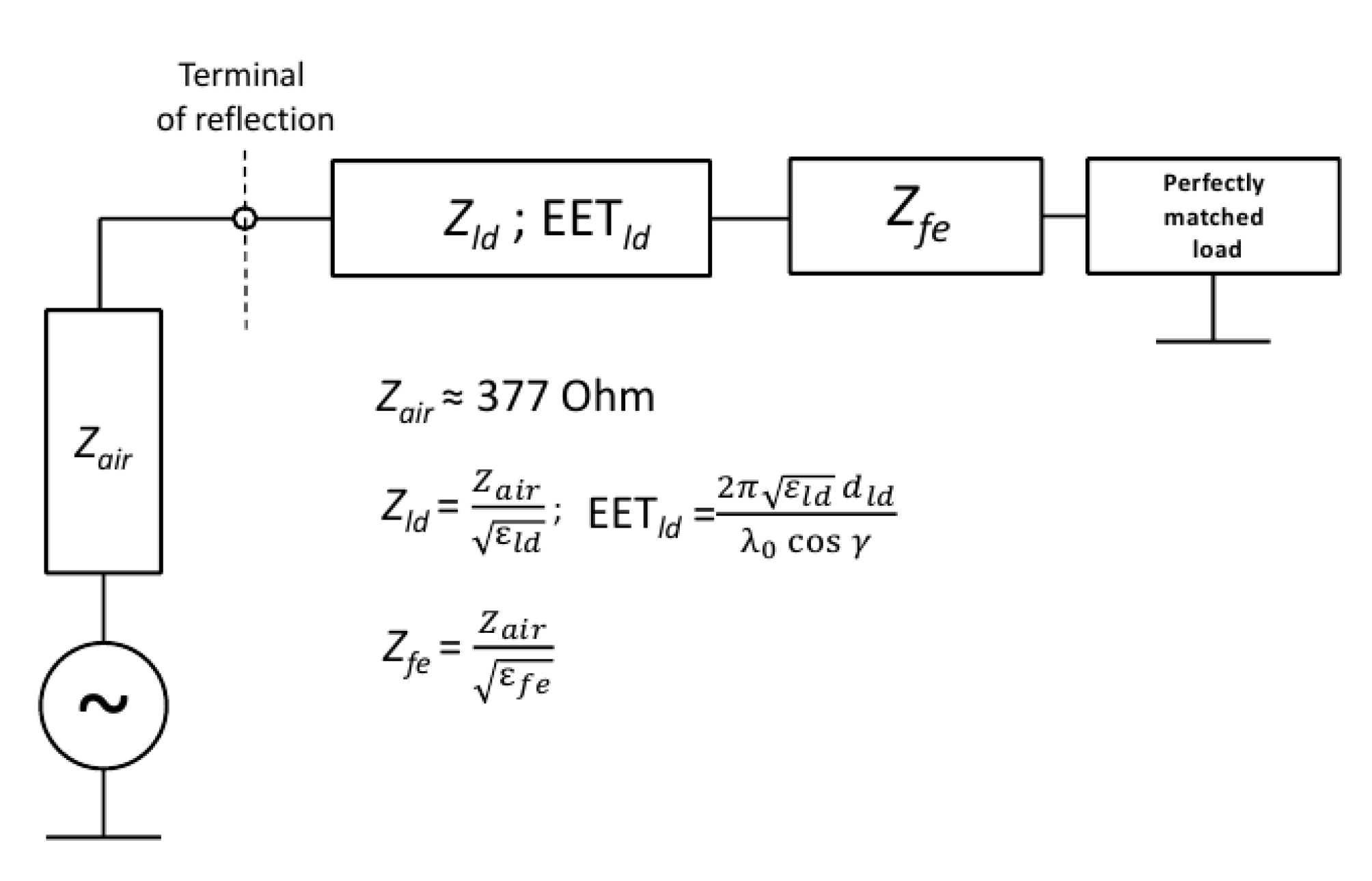
The simulation of the reflector’s operation in different conditions (indoor and outdoor) was performed to demonstrate the possibility of a controllable beam scan by the construction of the proposed reflector. During the simulation, the reflector model based on the FE plate with a thickness of 1 mm was used. The key parameters of the FE plate used in simulation corresponded to the measured FE material properties presented in the previous section. Thus, was 440 with a maximum tunability K = 1.6. The reflector’s operating frequency was ∼60 GHz. The quarter-wave transformer was used to match the FE reflector with the free space. During the simulation, a matching layer with permittivity = 20 and thickness = 0.3 was used. A dielectric plate with equal parameters was used as the matching layer in the manufactured FE reflector prototype and measured during this work (see Section 3.2). As was mentioned previously in Section 2.1, it is essential to minimize the wave reflection from the top boundary of the FE reflector structure to avoid the degradation of its radiation pattern. Thereby, the estimation of the reflection coefficient from the top side of the FE reflector at different incidence angles of electromagnetic waves was performed. To simplify this, we assumed the ferroelectric plate as a transmission line that was perfectly matched to a load; thus, it could be presented only by its characteristic wave impedance () (see Figure 2). This assumption allowed us to consider the reflection only at the interface between the matching layerand FE plates by using the impedance transformation formula. Note that the equivalent electrical thickness (EET) of the matching layer depended on the refraction angle as (see Figure 2). The equivalent electrical circuit is presented in Figure 4 with the corresponding equivalent parameters. It was clear that the non-zero angle of incidence may increase the reflections even for a layer perfectly matched in a condition of normal incidence.
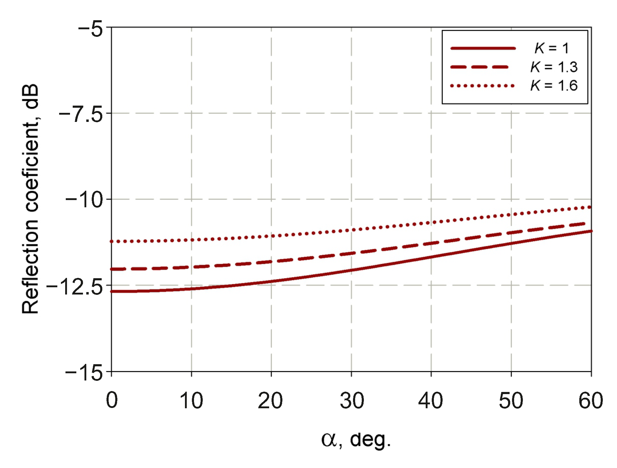
Simulation results for the dependencies of the reflection coefficient on the incident angle are presented in Figure 5. The results were calculated for different K limited by the maximum achievable tunability (K) of 1.6. The results showed that for K values up to 1.6, the reflection coefficient did not exceed −10 dB for the considered matching layer parameters at a wide range of angles of incidence.
The Radio Frequency module (Electromagnetic Waves, Frequency Domain interface) of the COMSOL Multiphysics software was used to perform the 2D electromagnetic simulation of the FE reflector device to prove the proposed beam deflection concept. One side of the FE plate was assigned as a perfect electric conductor (PEC) boundary to reflect the incoming wave. The reflector model consisted of a ferroelectric plate with a quarter-wavelength matching layer of a linear dielectric with parameters that corresponded to those considered previously. The dimension of the FE lens aperture was 10 (at 60 GHz) with the thickness of the FE plate being 1 mm. The FE plates were divided into 20 rectangular regions to provide the discrete spatial distribution of the phase shifts. The permittivity of each region was determined as , where (the ferroelectric permittivity without the control of the electric field ( = 440)) and (the tunability factor corresponding to the i-th FE region).
While performing a simulation of the radiation patterns, we considered possible cases to implement the ferroelectric reflector. The first corresponded to the outdoor system implementation, i.e., the reflector was irradiated by the plane wave, radiated by the source at a far distance (the far-field radiation condition). This condition can be satisfied by using any source antenna, but this would demand increasing the distance between the source antenna and the reflector models, which would increase the dimensions of the simulation area. To optimize the model and calculation time, we decided to use a highly directional horn antenna (∼30 dBi) placed at 30 from the reflector. The dimension of the horn aperture was 55 mm, and its length was ∼500 mm. The horn antenna used during the simulation was calculated using the method described in [20].
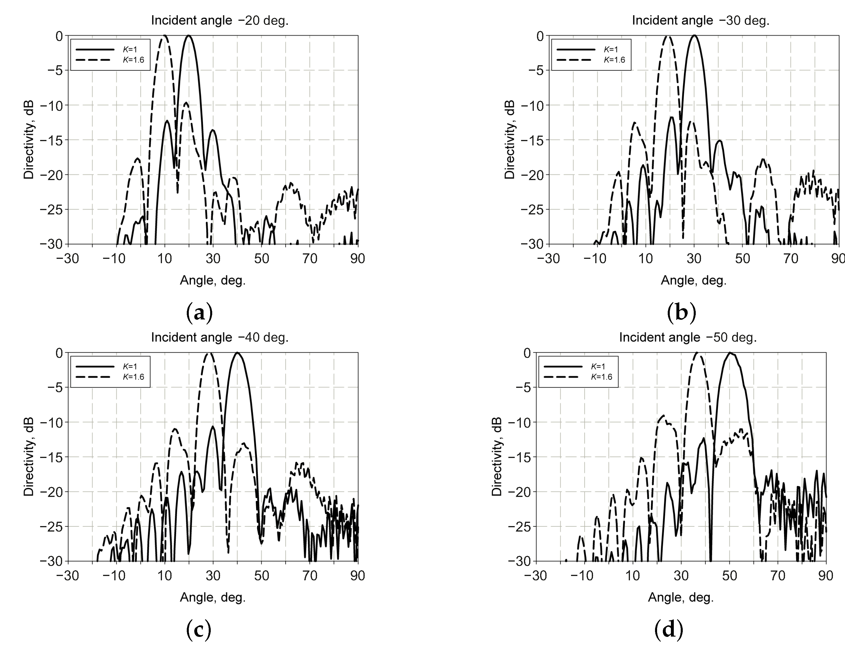
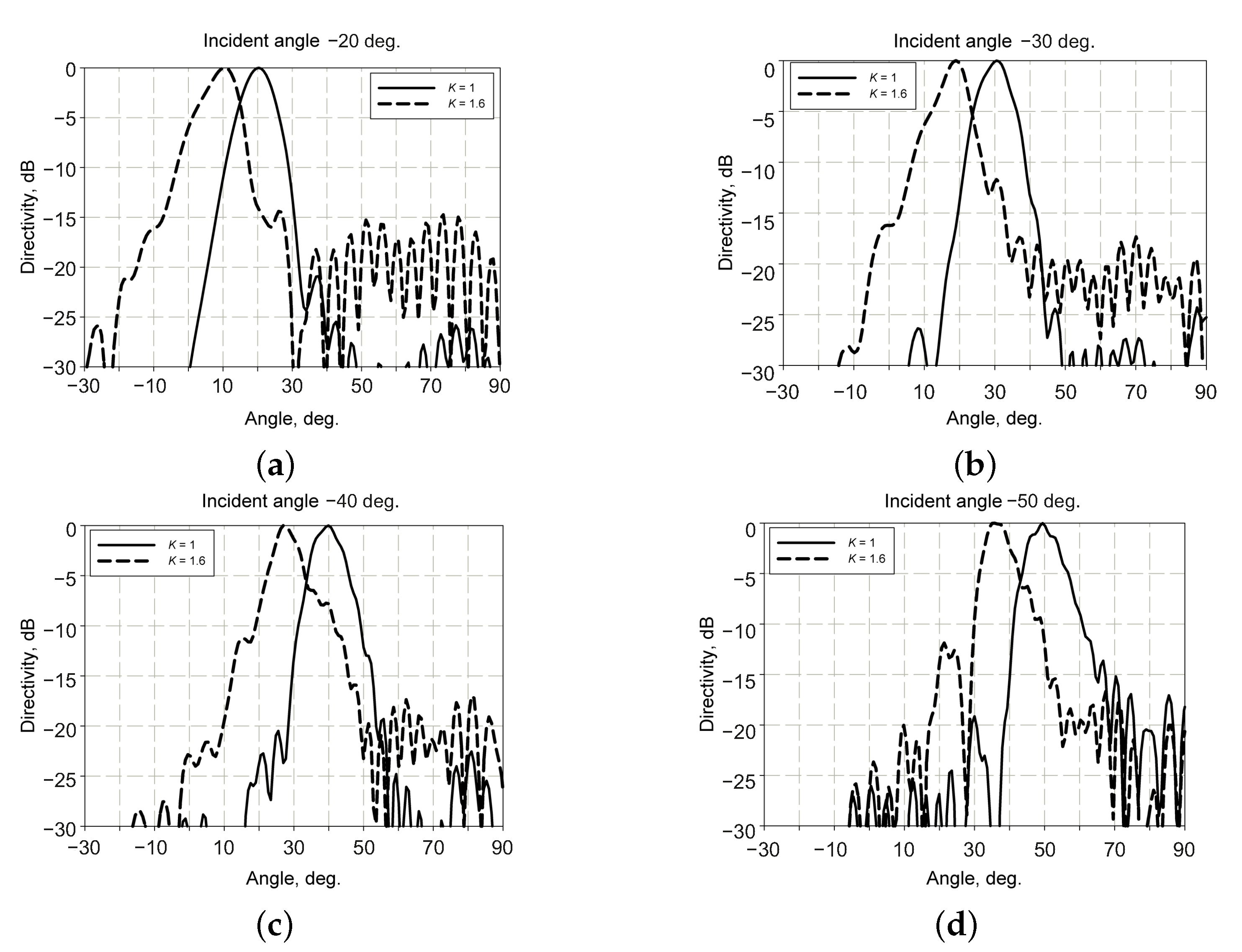
Figure 6 presents the simulated radiation patterns at 60 GHz for different incident angles from −20 deg. to −50 deg. Note that a direction of zero degrees was perpendicular to the reflector plane, while waves were incident at the negative angles (counterclockwise relative to the direction of zero degrees).
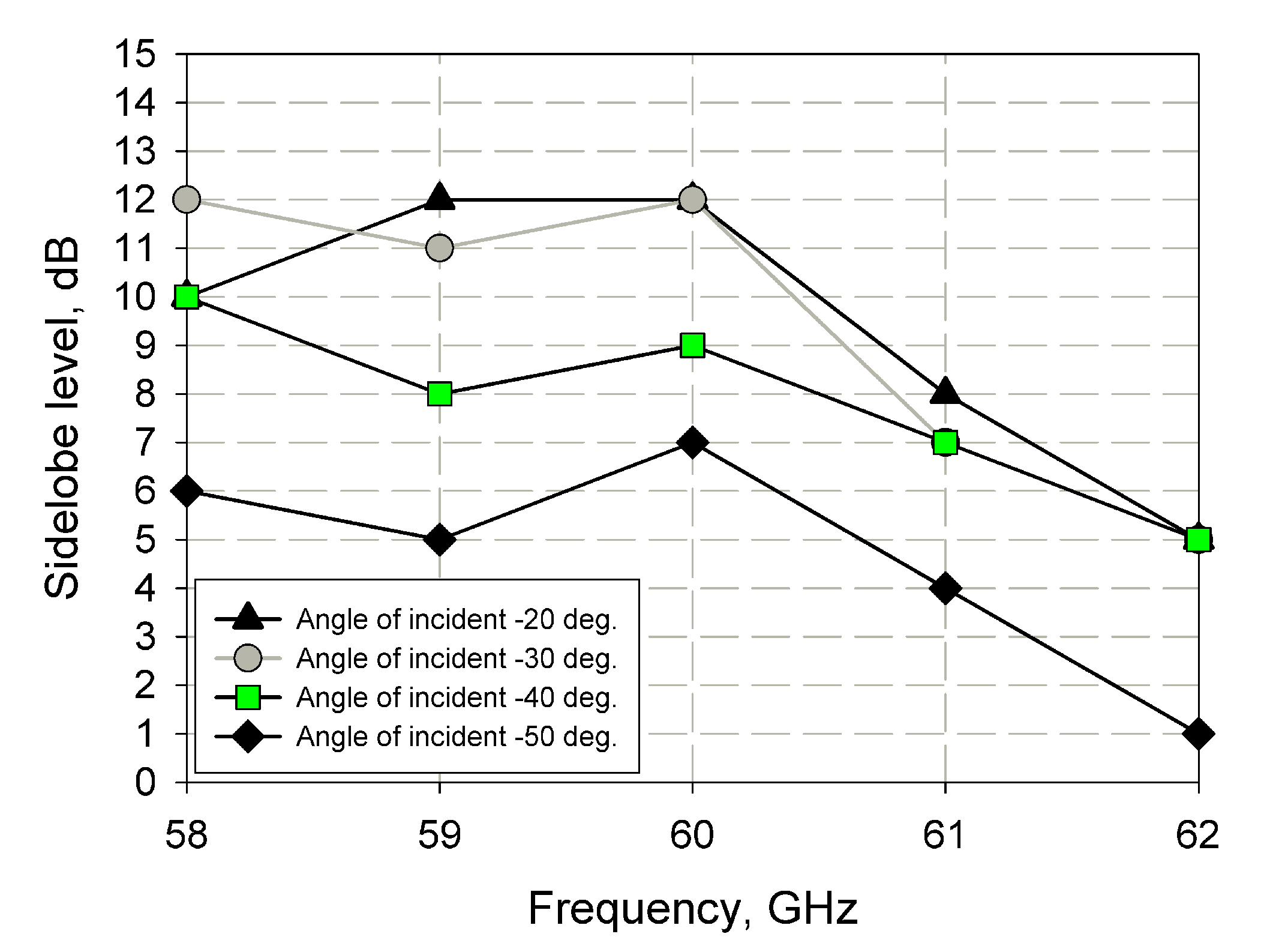
The results presented the main beam deflection up to ∼15 degrees relative to the beam position reflected in the absence of control (i.e., K = 1 along the reflector aperture). The level of the side lobes was less than 10 dB for incident angles from −30 and −40 deg., while the remaining angles demonstrated a slightly higher level of side lobes. The insufficient matching could explain such a level of side lobes. This conclusion was proven by the simulation dependence of the side lobe levels on the frequency at the different incident angles presented in Figure 7. The simulation was performed in the condition of maximum beam deflection (K = 1.6). The electromagnetic simulation results were in agreement with the calculations presented in Figure 5.
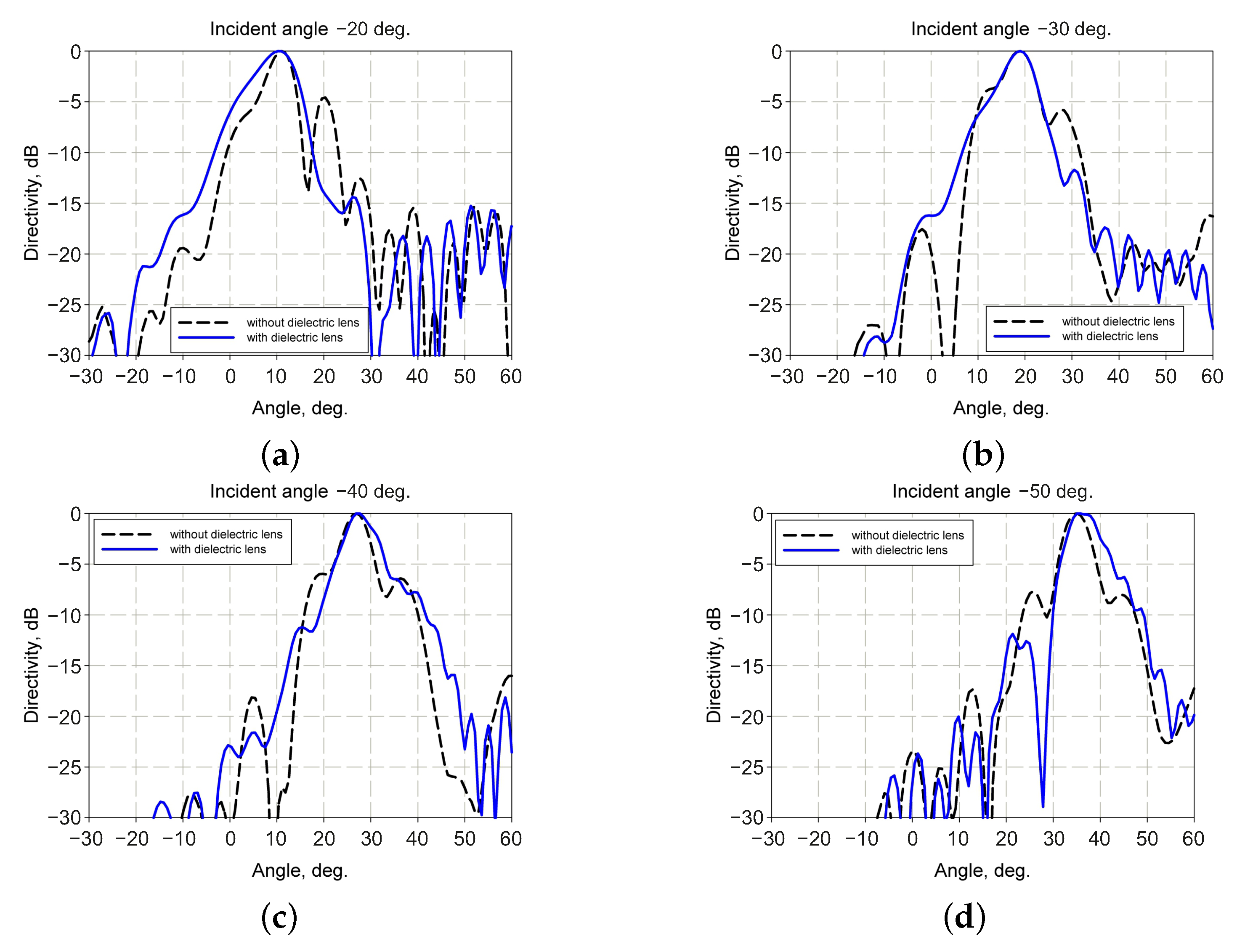
The second possible implementation of the reflector is an indoor system. In this case, the primary antenna may not be sufficiently directive to provide a plane wave incoming to the reflector due to a small aperture and/or small distance from the reflector. To perform a simulation corresponding to this case, the horn antenna with a directivity of ∼15 dBi was used as the primary antenna. The dimension of the horn aperture was 32 mm, and its length was ∼45 mm. The horn antenna used during the simulation was calculated using the method described in [20]. In this case, the distortion of the reflector’s radiation pattern could be caused not by poor impedance matching along, but by the wavefront curvature as well. The model with the dielectric lens placed between the primary antenna and reflector was simulated to estimate the wavefront curvature’s influence.
The dielectric lens profile was calculated using the method proposed in [21]. The dielectric lens parameters used in model were = 2.3, aperture size—10, focal distance—5.3. The horn antenna was placed at 20 from the reflector. The distance between the dielectric lens and the horn aperture was ∼.
The comparison of the simulated results for both models allowed us to conclude that the wavefront curvature had an influence on radiation pattern distortion. The simulated results are presented in Figure 8. Note that the simulation was performed in the condition of maximum beam deflection (K = 1.6). The simulation results showed that the use of the lens allowed significantly decreasing the level of the side lobes. Thereby, for the indoor application, the wavefront curvature of the incident wave was a dominant mechanism of reflector radiation pattern distortion.
The FE reflector simulation with the dielectric lens was performed at different incident angles to estimate the maximum scan angle values. The simulation results are presented in Figure 9.
Table 1 contains the simulation results of the deflection angle for both possible cases of application of the reflector (indoor and outdoor). One can see that the deflection angle values obtained at the same tunability (K = 1.6) for the different incident angles were not equal. This follows from the increasing effective thickness of the FE plate with the increase of the incident angles, i.e., increasing the wave path in the ferroelectric material with increasing incident angle. Comparing the simulation results for the outdoor and indoor implementation cases showed that the scan angle value was up to 15 degrees for both cases. However, the levels of the side lobes for the indoor case were better. This can be explained by the inhomogeneity of the incident wave amplitude’s spatial distribution caused by the dielectric lens, in contrast with the homogeneous wave radiated by the highly directive antenna used for the simulation of the outdoor implementation. Despite this, the flatness of the wavefront incoming to the reflector was important to consider for the reflector implementation. Note that the obtained results for the maximum scan angle were not limited by the reflector design. To increase this parameter, the FE layers with a higher thickness and/or and/or K should be used.
3.2. Experimental Results
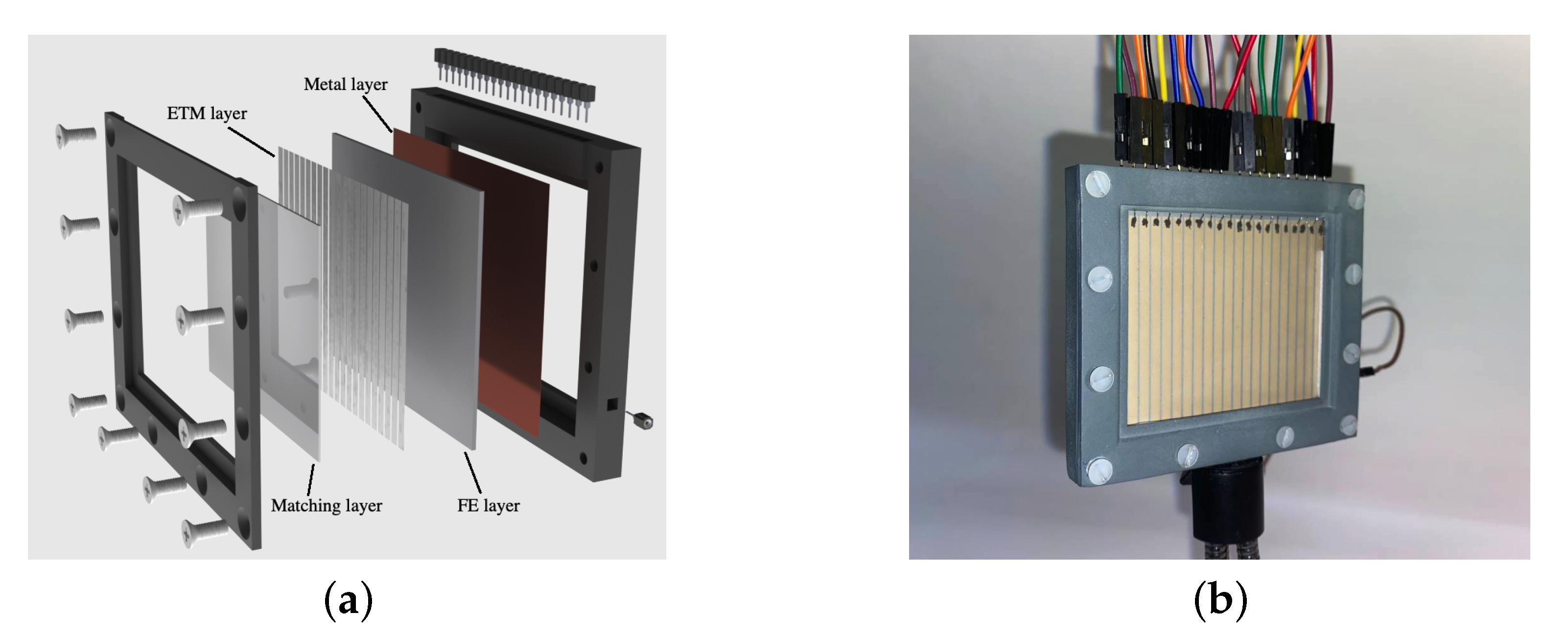
To confirm the possibility of electrically tunable beam deflection for the proposed FE reflector, a prototype with an operating frequency of 60 GHz was manufactured. Ferroelectric plates of BSTO with a surface area of 48 × 60 mm and a thickness of 1 mm were used. The description of BSTO production technology and its experimental characteristics were presented earlier in the Materials Subsection. One of the BSTO ceramic plates’ surfaces was metalized by the vacuum magnetron sputtering method. Oxygen-free copper with an adhesive chromium sublayer was chosen as the metal material. The residual pressure in the chamber did not exceed 6×10 Pa. Before deposition, ionic cleaning of the surface of the substrates in a glow discharge was carried out to improve the adhesion. High-purity argon at a pressure of 1 Pa was used as a plasma-forming gas. Sputtering of chromium and copper targets was carried out at direct currents at a power of 1.25 kW and an argon pressure of 0.1 Pa. The deposition temperature was kept constant at 300 C. The growth rate was 60 nm/min. As a result, a copper layer with a thickness of 2 m was deposited on the BSTO ceramic plate’s surface. On the opposite surface of the BSTO ceramic plate, the SI-Ti-Ce layer was deposited to form the ETM. The technology description of SI-Ti-Ce deposition on the BSTO ceramic and the experimental characteristics of the deposited Si-Ti-Ce films were presented earlier in the Materials Subsection. To form the topology of the ETM layer, the photolithography procedure was performed. Twenty-one discrete electrode sections that were electrically isolated from each other were formed. The holder providing the voltage application to the control electrodes was manufactured by 3D printing. The insertion loss value of the ferroelectric reflector prototype was estimated as ∼4 dB on the basis of the material measurements presented in the Materials Subsection. The exploded-view drawing and photo of the FE reflector prototype are presented in Figure 10.
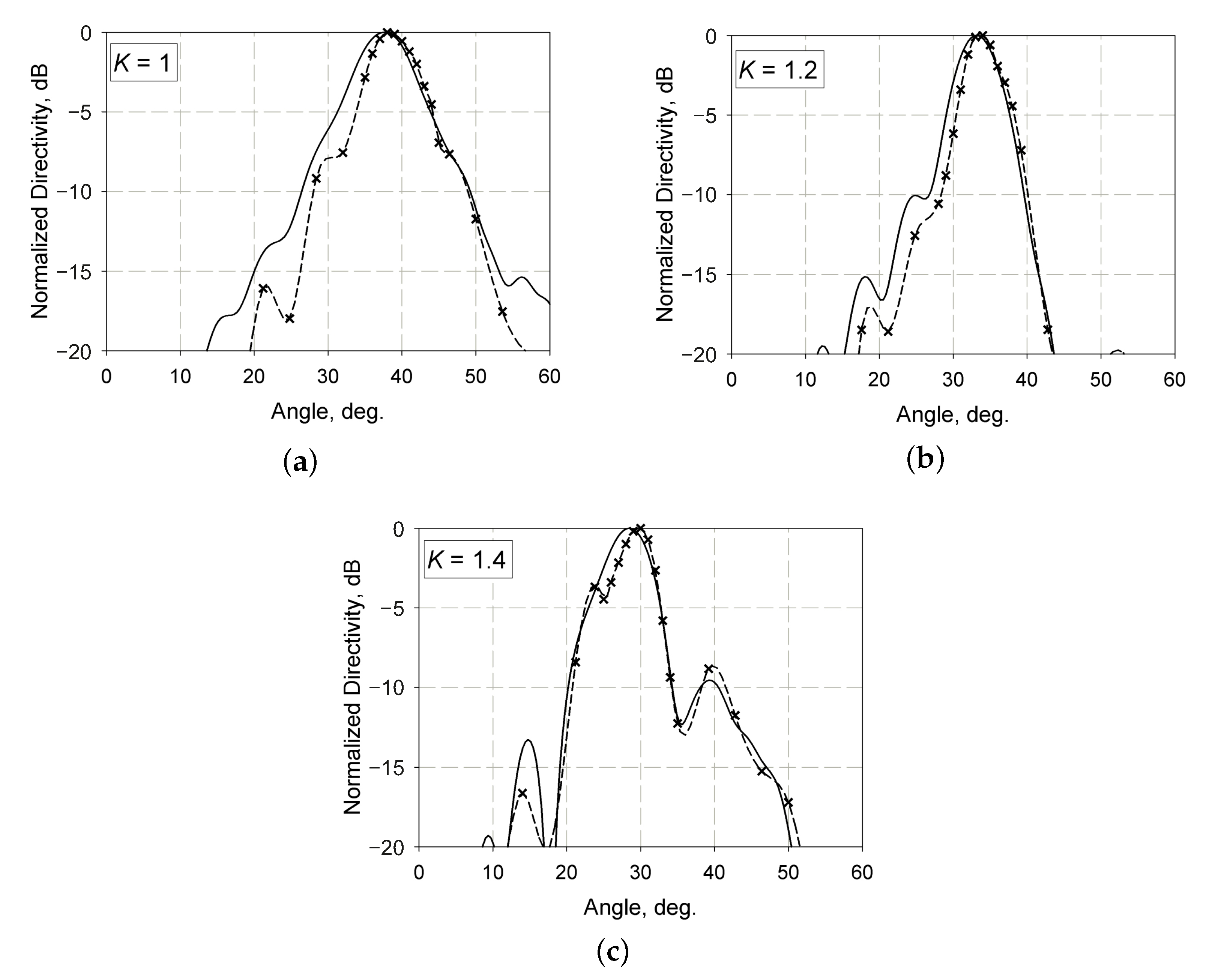
The conical horns with an aperture diameter of 30 mm were used as the source and detector antennas during the measurements of radiation patterns at 60 GHz. To provide the required control voltage applied to the ferroelectric ceramic during the experimental investigation of the prototype, we used a laboratory voltage source in combination with a self-made voltage up-conversion device. The maximum achievable voltage of this setup was limited to 5 kV, which corresponded to K = 1.4 for the ferroelectric ceramic plate used. During the experiment, the angle of incidence was ∼40 deg. The distance between the source antenna and the reflector was 60 mm. The model with the corresponding dimensions of the source antenna, the reflector aperture, and the distance between them was used to provide a comparison between the simulation and measurement results. Figure 11 presents the simulated and measured radiation patterns for different ferroelectric tunability values. The measured results showed that the deflection angle value of the reflector prototype was ∼8 deg, while the simulated one was about ∼10 deg. However, we should note that the most significant difference in the deflection angle could be observed at the highest tunability value (K = 1.4). The radiation pattern distortion could explain this due to the cumulative effect of poor impedance matching and incident wavefront curvature.
4. Conclusions
The design of an electrically tunable reflector based on FE materials was considered and analyzed. The absence of discrete elements in the reflector design simplified its construction and provided operation in the millimeter-wavelength range. The analysis of the possible application cases (indoor and outdoor) of the reflector design was performed. It was shown that for applications in indoor environments, the use of a dielectric lens to minimize the radiation pattern distortion is preferable. The simulation results based on the experimental characteristics of FE materials showed the effectiveness of the proposed reflector design. The value of the deflecting angle obtained during the simulation was ∼15 deg. This value can be significantly increased in several ways. One way is to use the FE layer from the same material, but with a higher thickness. Another one is to use FE materials with higher and/or K parameter values. The prototype measurements performed confirmed the possibility for electrically tunable beam deflection using the proposed FE reflector.
Note that the proposed reflector design provided the 1D scanning regime only. Its operation principle can be used for advanced reflector designs with the possibility of scanning in both directions. Another way is the use of the reflector consisting of several FE layers. The 2D scanning regime can be achieved by forming a permittivity gradient in both ferroelectric layers, but in orthogonal directions. Thereby, the distribution of the permittivity in each layer would determine the deflection of the beam in the corresponding direction.
The analysis of the reflector design showed that the high value of the control voltages was the main challenge. The maximum operating voltage (at the edge of the reflector aperture) was approximately 5 kV, which corresponds to K = 1.4. Note that a ferroelectric reflector operating at higher frequencies may require lower control voltage values. Since the wavelength at higher frequencies became smaller, the same value of the ferroelectric plate thickness would provide a higher phase shift. One way to decrease the control voltage is to use a multilayer structure composed of thinner ceramic plates where the control voltage would be applied to each layer. In this case, the control voltage value would decrease inversely to FE layer count in comparison to a single-layer ferroelectric reflector. Another way is the use of an FE material with a higher tunability and/or permittivity value.
Author Contributions
Conceptualization, A.A., R.P., and A.B.K.; modeling, R.P. and A.S.; prototype manufacturing, A.K. and A.S.; investigation, R.P. and A.S.; data analysis, A.A., R.P.; writing—review and editing, all authors; supervision, A.A., R.P., and A.B.K. All authors read and agreed to the published version of the manuscript.
Funding
This work was supported by the Russian Science Foundation under Grant 18-79-10156.
Institutional Review Board Statement
Not applicable.
Informed Consent Statement
Not applicable.
Data Availability Statement
The data presented in this study are available upon reasonable request from the corresponding author.
Conflicts of Interest
The authors declare no conflict of interest.
Appendix A
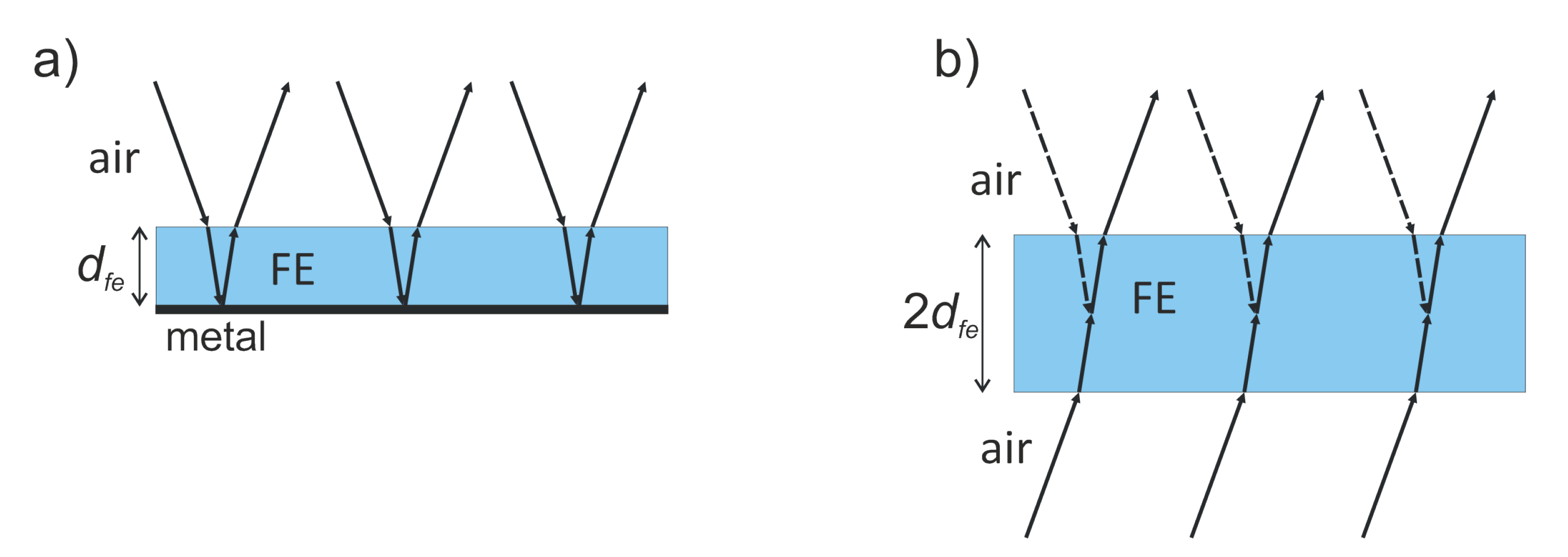
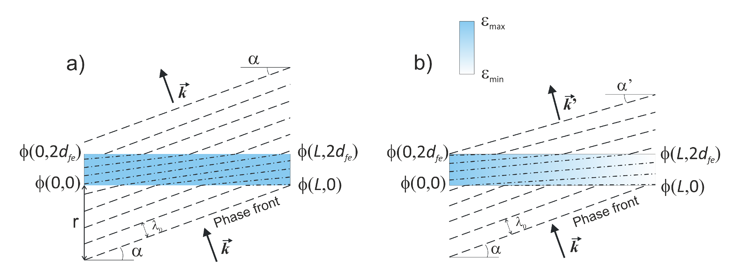
The derivation of Expression (2) is convenient to describe based on the assumption of the equivalence between the structures shown in Figure A1a,b. Figure A1a presents a ferroelectric (FE) plate with a thickness of and limited by the metal layer. The angle of incidence is equal to the angle of the reflected wave at the air–FE interface. In Figure A1b, the ferroelectric (FE) plate with a doubled thickness () and without metal is presented. In this case, one can see that after the FE plate, radiation propagates in the direction defined by the angle of incidence. For clarity, the direction of incident radiation is mirrored along the symmetry axis and depicted by dashed arrows. Thus, both structures demonstrate the same influence on the incident wave, which is changing the wave phase.
Figure A1.
Schematic of the equivalence between the reflection (a) and transmission (b) cases of the wave incident on the ferroelectric plate.
Figure A1.
Schematic of the equivalence between the reflection (a) and transmission (b) cases of the wave incident on the ferroelectric plate.

In more detail, this influence can be observed with the help of Figure A2a, where radiation is depicted by the wavefronts (dashed lines). The wave was incident on the air–FE interface at some angle () and, thus, had a phase difference at the endpoints of the FE plate , where L is the width of the FE plate. This phase difference is defined by the angle of incidence , which can be calculated from the following expression:
where r is the distance fromthe phase front point, which in turn can be defined as:
where is the phase propagation constant in the air; is the wavelength in the air. Thus, combining (A1) with (A2):
In the same way, the direction of the outcoming wave can be found from the phase difference . In the case of the constant permittivity () of the FE plate along its width, the phases at the air–FE and FE–air interfaces differ by a constant value, defined by , where is a phase propagation constant in the ferroelectric media. Thus, one can conclude that the direction of wave propagation is the same for the air–FE and FE–air interfaces.
Figure A2.
Schematic of the incident wave transmission through the ferroelectric plate with a constant permittivity value along the plate (a) and through the ferroelectric plate with the gradient permittivity distribution (b).
Figure A2.
Schematic of the incident wave transmission through the ferroelectric plate with a constant permittivity value along the plate (a) and through the ferroelectric plate with the gradient permittivity distribution (b).

However, for the gradient distribution of the ferroelectric permittivity along the plate width (see Figure A2b), the phase difference is not the same at the opposite interfaces. Thus, the direction angle () of the outcoming wave is not equal to the angle of incidence. One can write:
Since , one may rewrite (A4) as:
where K is the tunability factor of the ferroelectric material. Thereby, the deflection angle value () can be estimated as:
The expression (A6) provides an estimation of the deflection angle value on the basis of the ferroelectric plate’s permittivity, thickness, and width as a function of the ferroelectric tunability factor.
References
- Seker, C. A review of millimeter wave communication for 5G. In Proceedings of the 2018 2nd International Symposium on Multidisciplinary Studies and Innovative Technologies (ISMSIT), Ankara, Turkey, 19–21 October 2018; pp. 1–5. [Google Scholar]
- Xiao, M. Millimeter wave communications for future mobile networks (guest editorial), part i. IEEE J. Sel. Areas Commun. 2017, 35, 1425–1431. [Google Scholar] [CrossRef]
- Wang, X. Millimeter wave communication: A comprehensive survey. IEEE Commun. Surv. Tutor. 2018, 20, 1616–1653. [Google Scholar] [CrossRef]
- Rappaport, T. Overview of millimeter wave communications for fifth-generation (5G) wireless networks—With a focus on propagation models. IEEE Trans. Antennas Propag. 2017, 65, 6213–6230. [Google Scholar] [CrossRef]
- Wang, P. Unlicensed Spectrum Sharing with WiGig in Millimeter-wave Cellular Networks in 6G Era. In Proceedings of the GLOBECOM 2020—2020 IEEE Global Communications Conference, Taipei, Taiwan, 7–11 December 2020; pp. 1–6. [Google Scholar]
- Mohamed, E. An efficient paradigm for multiband WiGig D2D networks. IEEE Access 2019, 7, 70032–70045. [Google Scholar] [CrossRef]
- Rangan, S. Millimeter-wave cellular wireless networks: Potentials and challenges. Proc. IEEE 2014, 102, 366–385. [Google Scholar] [CrossRef] [Green Version]
- Haneda, K. 5G 3GPP-like channel models for outdoor urban microcellular and macrocellular environments. In Proceedings of the IEEE 83rd Vehicular Technology Conference (VTC Spring), Nanjing, China, 15–18 May 2016; pp. 1–7. [Google Scholar]
- Peng, Z. An effective coverage scheme with passive-reflectors for urban millimeter-wave communication. IEEE Antennas Wirel. Propag. Lett. 2015, 15, 398–401. [Google Scholar] [CrossRef]
- Khawaja, W. Coverage enhancement for mm wave communications using passive reflectors. In Proceedings of the 11th Global Symposium on Millimeter Waves (GSMM), Boulder, CO, USA, 22–24 May 2018; pp. 1–6. [Google Scholar]
- Ratni, B. Gradient phase partially reflecting surfaces for beam steering in microwave antennas. Opt. Express 2018, 26, 6724–6738. [Google Scholar] [CrossRef] [PubMed]
- Tahseen, M. Electronically Tunable Beam Scanning Reflectarray using Frequency Selective Surface. In Proceedings of the 2020 IEEE International Symposium on Antennas and Propagation and North American Radio Science Meeting, Montreal, QC, Canada, 5–10 July 2020; pp. 73–74. [Google Scholar]
- Kong, D. Electronically Beam-Scanning Antenna with Active Slot Frequency Selective Surface for 5G Base Stations. In Proceedings of the 2020 IEEE MTT-S International Wireless Symposium (IWS), Shanghai, China, 17–20 May 2020; pp. 1–3. [Google Scholar]
- Rotshild, D. Innovative Reconfigurable Metasurface 2-D Beam-Steerable Reflector for 5G Wireless Communication. Electronics 2020, 9, 1191. [Google Scholar] [CrossRef]
- Ratni, B. Active metasurface for reconfigurable reflectors. Appl. Phys. A 2018, 124, 1–8. [Google Scholar] [CrossRef]
- Rotshild, D. Wideband reconfigurable entire Ku-band metasurface beam-steerable reflector for satellite communications. IET Microw. Antennas Propag. 2018, 13, 334–339. [Google Scholar] [CrossRef]
- Platonov, R. A Tunable Beamforming Ferroelectric Lens for Millimeter Wavelength Ranges. Coatings 2020, 10, 180. [Google Scholar] [CrossRef] [Green Version]
- Kotelnikov, I.V. Electrodeless measurement technique of complex dielectric permittivity of high-K dielectric films in the millimeter wavelength range. Prog. Electromagn. Res. 2016, 52, 161–167. [Google Scholar] [CrossRef] [Green Version]
- Dorofeev, I. Small-sized body influence on the quality factor increasing of quasioptical open resonator. Opt. Quantum Electron. 2017, 49, 1–10. [Google Scholar] [CrossRef]
- Stutzman, W.; Thiele, G. Antenna Theory and Design, 2nd ed.; John Wiley & Sons: Hoboken, NJ, USA, 2012. [Google Scholar]
- Thornton, J.; Huang, C. Modern Lens Antennas for Communications Engineering, 1st ed.; John Wiley & Sons: Hoboken, NJ, USA, 2013. [Google Scholar]
Figure 1.
Schematic of the proposed ferroelectric reflector.

Figure 2.
Schematic of the proposed ferroelectric reflector.

Figure 3.
Experimentally measured FE permittivity dependence on the electric field strength.

Figure 4.
Equivalent electrical circuit for the calculation of the reflection coefficient.

Figure 5.
Reflection coefficient dependency on the incident angle at 60 GHz.

Figure 6.
Simulated radiation patterns for outdoor implementation of reflector at at different incident angles form (a) −20 (b) −30 (c) −40 (d) −50 deg. for 60 GHz operating frequency.
Figure 6.
Simulated radiation patterns for outdoor implementation of reflector at at different incident angles form (a) −20 (b) −30 (c) −40 (d) −50 deg. for 60 GHz operating frequency.

Figure 7.
Simulation results of the side lobe level for different angles of the incidence in the frequency range.
Figure 7.
Simulation results of the side lobe level for different angles of the incidence in the frequency range.

Figure 8.
Simulated radiation patterns for primary horn with and without dielectric lens at different incident angles form (a) −20 (b) −30 (c) −40 (d) −50 deg. for a 60 GHz operating frequency.
Figure 8.
Simulated radiation patterns for primary horn with and without dielectric lens at different incident angles form (a) −20 (b) −30 (c) −40 (d) −50 deg. for a 60 GHz operating frequency.

Figure 9.
Simulated radiation patterns at different incident angles from (a) −20 (b) −30 (c) −40 (d) −50 deg. for indoor implementation of the reflector operating at 60 GHz.
Figure 9.
Simulated radiation patterns at different incident angles from (a) −20 (b) −30 (c) −40 (d) −50 deg. for indoor implementation of the reflector operating at 60 GHz.

Figure 10.
Exploded-view drawing (a) and photo (matching layer removed) (b) of the FE reflector prototype.
Figure 10.
Exploded-view drawing (a) and photo (matching layer removed) (b) of the FE reflector prototype.

Figure 11.
Comparison of the measured radiation patterns (dashed lines) and the simulated ones (solid lines) corresponding to different tunability values: K = 1—(a); K = 1.2—(b); K = 1.4—(c).
Figure 11.
Comparison of the measured radiation patterns (dashed lines) and the simulated ones (solid lines) corresponding to different tunability values: K = 1—(a); K = 1.2—(b); K = 1.4—(c).


Table 1.
The simulation results of the deflection angle.
| Angle of Incidence, deg | Angle of Deflection at K = 1.6, deg. | |
|---|---|---|
| Indoor Case | Outdoor Case | |
| −20 | 11 | 10.5 |
| −30 | 12 | 11 |
| −40 | 14 | 13 |
| −50 | 15 | 14.5 |
Publisher’s Note: MDPI stays neutral with regard to jurisdictional claims in published maps and institutional affiliations. |
© 2021 by the authors. Licensee MDPI, Basel, Switzerland. This article is an open access article distributed under the terms and conditions of the Creative Commons Attribution (CC BY) license (https://creativecommons.org/licenses/by/4.0/).
Share and Cite
MDPI and ACS Style
Platonov, R.; Altynnikov, A.; Komlev, A.; Sosunov, A.; Kozyrev, A.B. Millimeter-Wave Reflector Based on a Ferroelectric Material with Electrical Beam Steering. Crystals 2021, 11, 585. https://0-doi-org.brum.beds.ac.uk/10.3390/cryst11060585
AMA Style
Platonov R, Altynnikov A, Komlev A, Sosunov A, Kozyrev AB. Millimeter-Wave Reflector Based on a Ferroelectric Material with Electrical Beam Steering. Crystals. 2021; 11(6):585. https://0-doi-org.brum.beds.ac.uk/10.3390/cryst11060585
Chicago/Turabian StylePlatonov, Roman, Andrey Altynnikov, Andrey Komlev, Alexei Sosunov, and Andrey B. Kozyrev. 2021. "Millimeter-Wave Reflector Based on a Ferroelectric Material with Electrical Beam Steering" Crystals 11, no. 6: 585. https://0-doi-org.brum.beds.ac.uk/10.3390/cryst11060585
Note that from the first issue of 2016, this journal uses article numbers instead of page numbers. See further details here.