Article

Microwave Absorption Performance of Single-Layer and Multi-Layer Structures Prepared by CNTs/Fe3O4 Nonwoven Materials

1
School of Textile and Clothing, Nantong University, Nantong 226019, China
2
School of Mechanical Engineering, Nantong University, Nantong 226019, China
*
Author to whom correspondence should be addressed.
Submission received: 8 July 2021 / Revised: 14 August 2021 / Accepted: 20 August 2021 / Published: 22 August 2021
(This article belongs to the Special Issue Synthesis, Properties, and Applications of Functional Nanocomposites)

Abstract

:
Electromagnetic radiation can cause serious harm to the human body, such as the rise in body temperature and the decrease in immune function. In this study, the carbon nanotubes (CNTs)/Fe3O4 nonwovens were used to prepare wearable flexible absorbing materials. First, the single-layer absorbing structures were prepared by hot rolling, dipping, and film fabrication, respectively. Then, the single-layer structures were combined to form the multi-layer absorbing structures. By testing and analyzing the absorbing performance of various structures in the X-band frequency range, the optimum combination scheme was found, together with a good reflection loss value of CNTs/Fe3O4 nonwoven material. The experiment results displayed that the single-layer hot-rolled nonwovens modified by CNTs have the best wave absorbing performance. Its minimum reflection loss of −18.59 dB occurred at 10.55 GHz, and the efficient frequency occurred at 8.86–12.40 GHz. The modified film can significantly improve the absorbing performance of multi-layer structures. In addition, the absorbing performance was closely related to both the place where the absorbing film was introduced and the type of absorbing fillers. When the film-forming CNTs (FC) film was located at the bottom layer of the multi-layer structure, the hot rolled CNTs hot rolled mixed reagent film forming CNTs (HC-HM-FC) structure constructed exhibited the best absorbing effects. Its minimum reflection loss can reach −33 dB, and the effective absorbing frequency range covered half of the X-band.

1. Introduction

Currently, the electronics industry is booming with the rapid development of technology. On the other hand, this has also caused a lot of electromagnetic pollution [1,2].
Electromagnetic radiation can cause a range of damage, including rising body temperature, nervous system dysfunction and weakened immune function [3,4]. Therefore, the research on wearable absorbing material and its structure is of great significance for the human body to resist electromagnetic wave damage.
The CNTs have a high length-diameter ratio and significant electrical conductivity. Inspired by its good conductivity, the electromagnetic interference (EMI)-shielding performance and mechanism of CNTs composites have become the subject of much research. One such study reported 9 wt.% CNTs/ 91 wt.% acrylic resin composites containing a remarkable shielding effectiveness (SE) of more than 25 dB in frequency range from 30 MHz to 5 GHz [5], which is mainly a result of the absorption of electromagnetic radiation.
Moreover, three dimensional micro structures of CNTs composites have shown superiority in EMI-shielding. For example, 0.66 wt.% CNTs sponge/ 99.34 wt.% epoxy composite showed an EMI shielding effectiveness of around 33 dB in the X-band [6], which is higher than that of 20 wt.% conventional CNTs / 80 wt.% epoxy nanocomposites. Another 3D 2.76 wt.% Fe3O4-CNTs/ 0.24 wt.% rGO Foam/ 97% EP nanocomposites displayed high electromagnetic interference SE value of 36 dB within the X-band, an almost 482% enhancement compared to Fe3O4-CNTs/ EP nanocomposites without three-dimensional structure (approximately 6 dB) [7]. Both the rGO Foam 3D framework and presence of high magnetic Fe3O4 were thought to be the result of super performance of EMI shielding in CNTs composites.
These previous research have shown that the high EMI shielding performance of CNTs composites comes from the absorption of electromagnetic radiation, and the high magnetic Fe3O4 can enhance the electromagnetic wave absorption. Therefore, we consider whether we can build an efficient 3D Fe3O4/CNTs network, so that we may get some materials with outstanding electromagnetic wave absorption properties.
Absorbing material refers to a kind of functional material that weakens or disappears electromagnetic waves by absorbing and attenuating incident electromagnetic waves and effectively converting electromagnetic energy into heat or other forms of energy [8]. Textile materials, especially nonwoven fabric, have the advantages of inherent 3D structure, low areal density, thin thickness, and good flexibility, which is the main raw material for preparing wearable absorbing materials [9,10]. In order to analyze the influence of material structure and thickness on sound absorption performance, Tiuc et al. prepared absorbing material using textile as the raw material and polyurethane foam as an adhesive, and characterized the acoustic properties of the produced material [11]. Song et al. prepared absorbing material with silica fabric as a raw material, combined with a freeze-drying method. The prepared material, which has high tensile strength and thermal stability, can effectively absorb X-band microwaves [12]. Bi et al. [13] processed carbonyl iron / graphene aerogel/ nonwoven, which was found to have a wide efficient bandwidth in X-band. By an in situ synthesis method, Egami et al. [14] found a stack of ten polypyrrole-coated conductive non-woven fabric sheets show nearly no efficient bandwith in X-band range.
At present, the research on the absorbing function of textile materials is mainly focused on the absorbing agents [15,16,17,18], and there is limited research on enhancing the absorbing function by constructing new textile material structures. These studies either have poor electromagnetic absorbing performance or require complex processing technology. In our research, we try to use common textiles and common textile finishing technology to construct 3D electromagnetic absorbing textiles, and wish to test different electromagnetic absorbing performance in varied multi-layer structures, which are derived from those 3D electromagnetic absorbing textiles. Firstly, we chose needle punched nonwoven as matrix. As needle punched nonwoven has naturally irregular porous structures by the tangling of staple fibers, it may be helpful in constructing the efficient microwave absorbing structures. Secondly, we employed two kinds of common textile treatments to process the nonwovens, which were the hot rolling process and the dipping process. These two processing methods will have completely different effects on the structure of nonwovens. The hot rolling process will process the nonwovens under heating and pressing conditions, while dipping process submerges the nonwovens into the impregnation solution. In addition, considering the cost of dipping process, we added another treatment of film forming, to observe whether or not a film, without the support of a nonwoven skeleton, could play the same role as that of an impregnated nonwoven, which has the support of a nonwoven skeleton. In this paper, the CNTs and Fe3O4 powder were used to modify non-woven fabrics, and a variety of single-layer absorbing structures were prepared by the methods of hot rolling, dipping, and film fabrication. After that, the multi-layer absorbing structures were constructed by the single-layer absorbing structures. The absorbing performances of all absorbing structures were tested, and the relationship between the multi-layer structures and electromagnetic absorbing performances were analyzed to find the optimal combination scheme, together with a good reflection loss value of CNTs/Fe3O4 nonwoven material.

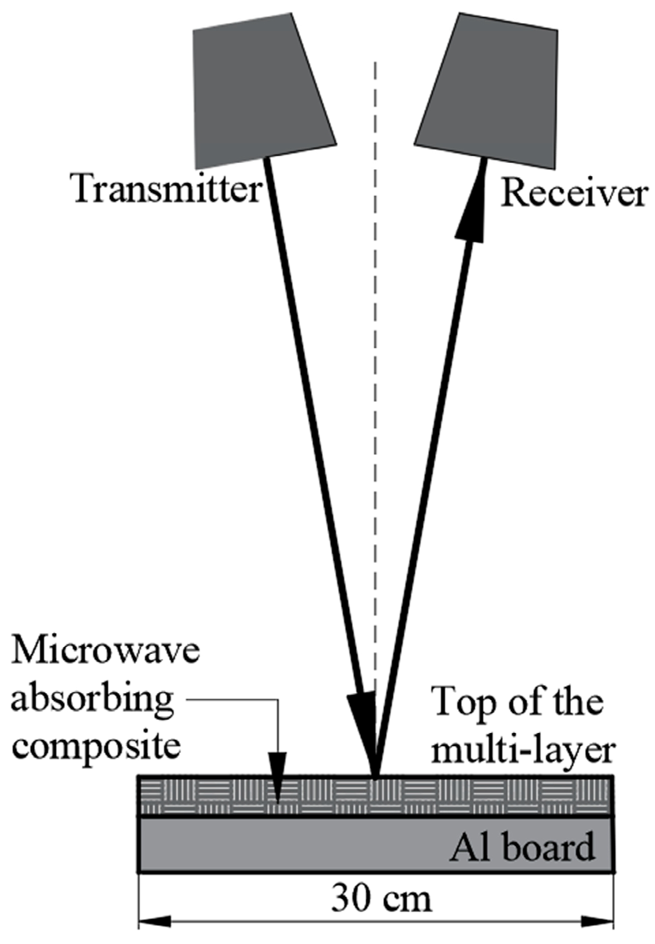
2. Materials and Methods

2.1. Materials and Instruments

The raw materials used in the experiment included waterborne polyurethane, defoaming agent, dispersing agent, thickening agent, 1 mm polyester (PET) needle-punched cloth, 2 mm PET needle-punched cloth and deionized water. The absorbing agents used in the experiment included three types, namely carbon nanotubes (CNTs, tube diameter 40nm, tube length 5–10 μm), Fe3O4 powder (500 nm) and mixed reagent (CNTs and Fe3O4 powder are mixed at a ratio of 1:1).
During the experiment, electronic balance (HC311, Shanghai Huachao Industrial Co., Ltd, Shanghai, China) was used to weigh objects. Cantilever electric stirrer (LC-QES-60, Shanghai Lichen Technology Instrument Co., Ltd, Shanghai, China) was used to stir the solution. Hot-rolling mill (RJ-50T, Geili Machinery Group Co. Ltd, Putian, China) was used to hot-roll the processed nonwoven fabric.
The Fabric Thickness Gauge (YG(B)141D, Wenzhou Darong Textile Instrument Co., Ltd, Wenzhou, China) was used to determine the thickness of the test piece. According to the national standard GB/T3820-1997 [19], suitable pressing foot area and molding pressure were selected. Five positions of the sample were randomly selected for measurement, and the average value was used as the final result.
Based on the measurement methods for reflectivity of radar absorbing material (GJB 2038A-2011) [20], the AV3672C vector network analyzer (China Electronics Technology Group Corporation, Qingdao, China) was used to measure the absorbing performance of the material, with the test frequency band of X-band, of which the frequency ranged from 8.2 GHz to 12.4 GHz. The X-band belongs to the microwave part of the electromagnetic spectrum, and is one of the commonly used microwave absorption experimental bands. We tried to find some functional possibility in daily materials, especially nonwovens. The corresponding wavelengths of 8.2–12.4 GHz frequency range is 36.6–24.2 mm. If an absorber contains the depth of half wavelengths, it will fit with the conditions of destructive interference, which is beneficial to its absorption performance. However, it demands a large thickness. Therefore, we want to check whether or not multi-layer material has such an advantage at a small thickness of several millimeters. During the absorbing performance test, the sample size was set as 30 cm × 30 cm, and an Al board with the same size as that of the sample was used as a holder to reflect the transmitted wave back to the receiver, as shown in Figure 1.
In the actual measurements of absorbing performance of specimen, the thickness will have a great influence on the X-band absorption [21]. In the process of hot rolling and film preparation, it is difficult to maintain the same thickness in the case of compound of different fillers and processes. In order to study the influence of fillers on absorbing performance under the condition of controlled variables, the thickness of the material is normalized. The obtained reflection loss per unit thickness was used to compare the absorbing performance of various materials with the thickness of 1 mm fabricated from different preparation processes. The calculation formula of reflection loss per unit thickness is as follows:
R = Reflection   loss   ( dB ) / Depth   ( mm )

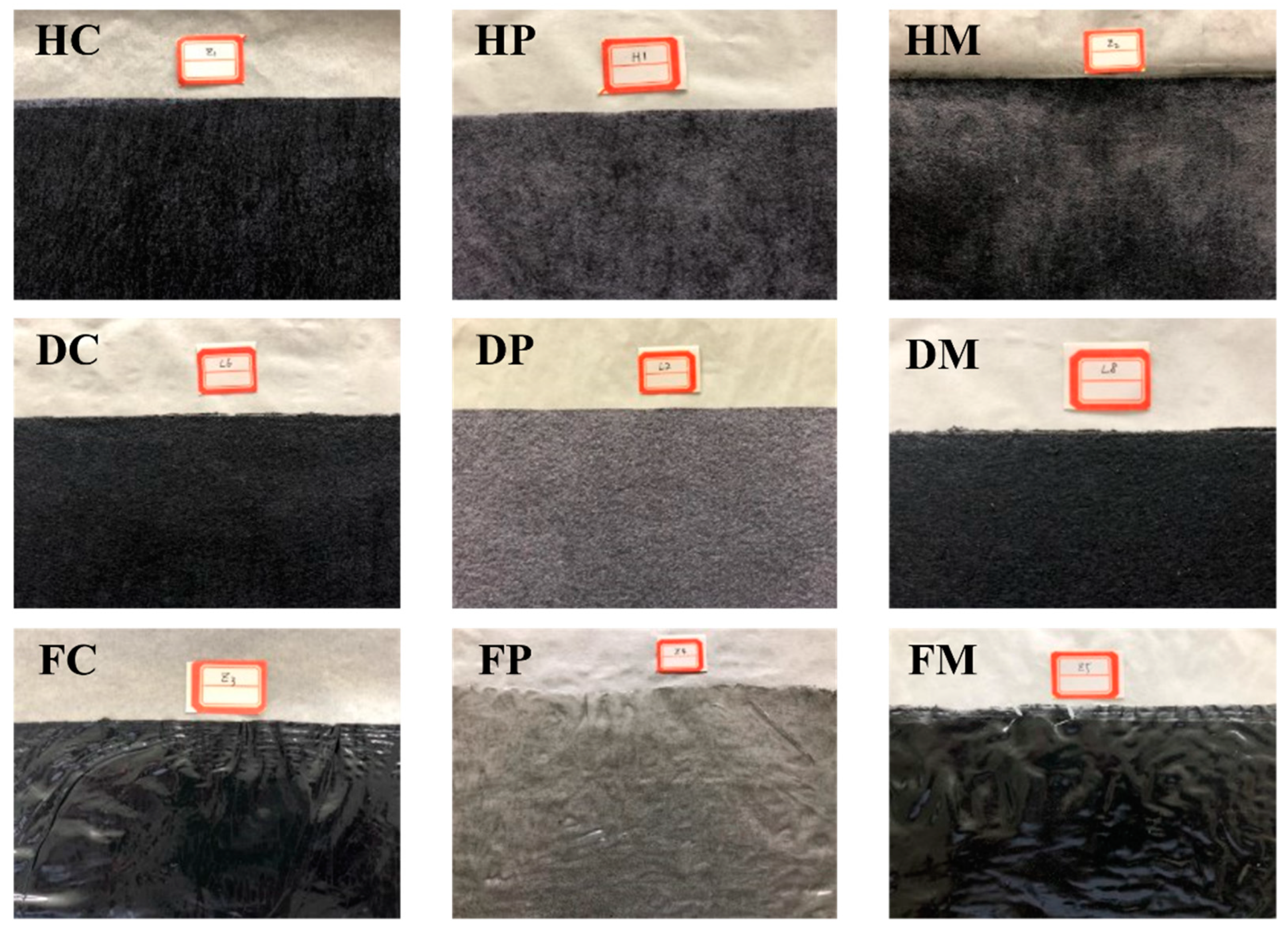
2.2. Preparation of Samples

In this experiment, three kinds of materials with different absorbing structures were constructed, namely hot-rolled nonwoven, impregnated nonwoven, and absorbing film. The three matrixes are matched with CNTs Fe3O4 powder, and mixed agent, respectively. Therefore, there are 9 different absorbing structures, as shown in Table 1. The sample preparation process is shown in Figure 2. The PET needle-punched cloth with the thickness of 2 mm is first immersed in a waterborne CNTs (mixed agent) dispersion and then hot-rolled to obtain the CNTs (mixed agent) hot-rolled cloth. The upper and lower surfaces of the PET needle-punched cloth with the thickness of 2 mm are coated with Fe3O4 powder and then hot rolled to obtain Fe3O4 hot-rolled cloth. Different from the impregnation or film-forming process, the hot rolled process treats the PET needle-punched cloth under heating and pressure, so the thickness of hot rolled cloth becomes much thinner than that of the impregnated cloth or film. Considering that thickness had a significant effect on the microwave absorption, the PET needle-punched cloth with the thickness of 2 mm was chosen to fabricate the hot rolled cloth, thus the thickness of prepared hot rolled cloth would be close to that of the other two processing techniques. The CNTs (Fe3O4 powder and mixed agent) was mixed with waterborne polyurethane and stirred. After the foam disappears, it is poured into a glass mold and then poured into deionized water. After soaking, the coagulated reagent was removed and flattened with a tablet to obtain three absorbing films. The depth of the mold used to prepare the absorbing film was 1 mm. However, the film wrinkled during its curing, leading to an uneven surface of the absorbing film, resulting a thinner thickness of the absorbing film once flattened, i.e., less than 1 mm. Needle-punched material was soaked in a glass mold, in which appropriate waterborne polyurethane can submerge the entire material. Three kinds of dipped cloths were obtained with different fillers. The pictures of the samples prepared by the above process are shown in Figure 3.

3. Experimental Results and Discussions

3.1. Single-Layer Absorbing Structures

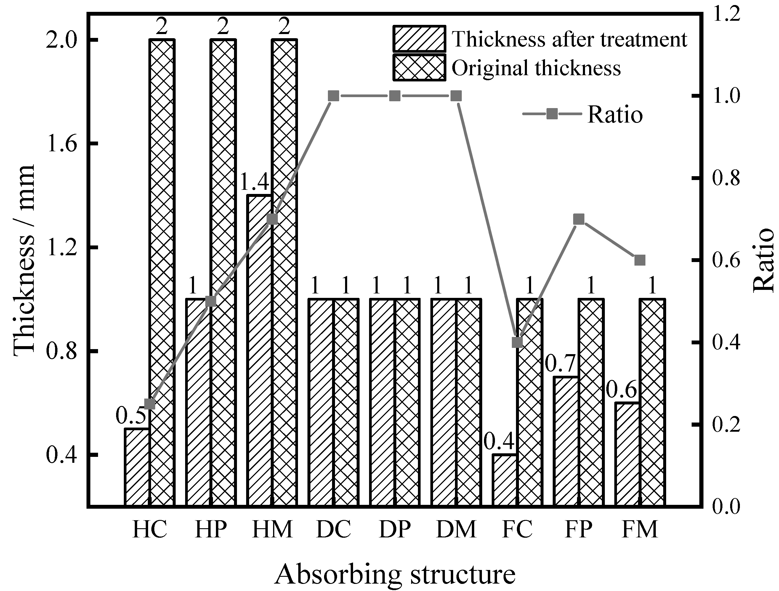
3.1.1. Thickness Test

The results of thickness tests on single-layer absorbing structures are shown in Figure 4.
As can be seen from Figure 4, the different fillers will affect the thickness of hot-rolled cloth to varied levels. Among them, the thickness of HC and HM are the lowest and the highest, respectively. HC, HP, and HM are all fabricated by hot-rolling process from needle-punched PET material in a thickness of 2 mm. Their difference lies in the different fillers, which are CNTs, Fe3O4 powder and hybrid fillers, respectively. After the PET needle-punched cloth is impregnated and knife-coated, the tubular CNTs dispersed in the aqueous solution are dispersed into the pores of the PET needle-punched cloth along with the flow [22]. As the CNTs itself is negatively charged [23], it can be easily adsorbed onto the surface of the polyester fiber when they meet. As a result, positive and negative charges are induced on the fiber surface. Under the condition of hot rolling, the fibers are re-oriented under the action of electric charge. Therefore, a very large thickness loss happened after a short period of hot rolling. The Fe3O4 powder, a kind of uncharged particle, is dispersed into the voids of the needle-punched fiber through vibrating screen. During the hot rolling process, the pores of the PET needle-punched cloth are partially softened under the action of thermal pressure and are squeezed and collapsed, resulting in a decrease in thickness. The hybrids of CNTs and Fe3O4 powder will lead to a more special situation, as the Fe3O4 particles dispersed in the CNTs aqueous solution will be attracted by the negatively charged tubular CNTs and form a special 3D (three-dimensional) structure. This special structure will not only hinder the flow of mixed particles with softened fibers under the action of hot rolling, but also help to set up much more minute three-dimensional spaces, which hinder each other with the gaps of the needle-punched material. In addition, the high strength of CNT allows it to maintain a very large thickness under hot rolling. As can be seen in Figure 4, the thickness of impregnated cloth is relatively uniform. In order to ensure the thickness of impregnated cloth, the amount of impregnating solution added needs to be controlled to the extent that the needle-punched material has just been immersed. In addition, it can be found that the film thickness has a great relationship with the type of filler particles. The filler particles are equivalent to a nucleating agent, which can induce crystallization. In contrast, tubular CNTs are more advantageous than Fe3O4 particles and mixed particles, as the linear shape is more conducive to inducing the dense arrangement of macromolecular chains. Although the mixed particles have a 3D structure, one-dimensional linear CNTs can still effectively induce crystallization during the formation of the polyurethane macromolecular chain. However, when the uncharged Fe3O4 particles is used as filler, the thickness of the polyurethane has increased. Uncharged Fe3O4 particles can increase crystal nucleus, but cannot promote the dense arrangement of molecular chains, thus their thickness is the largest.

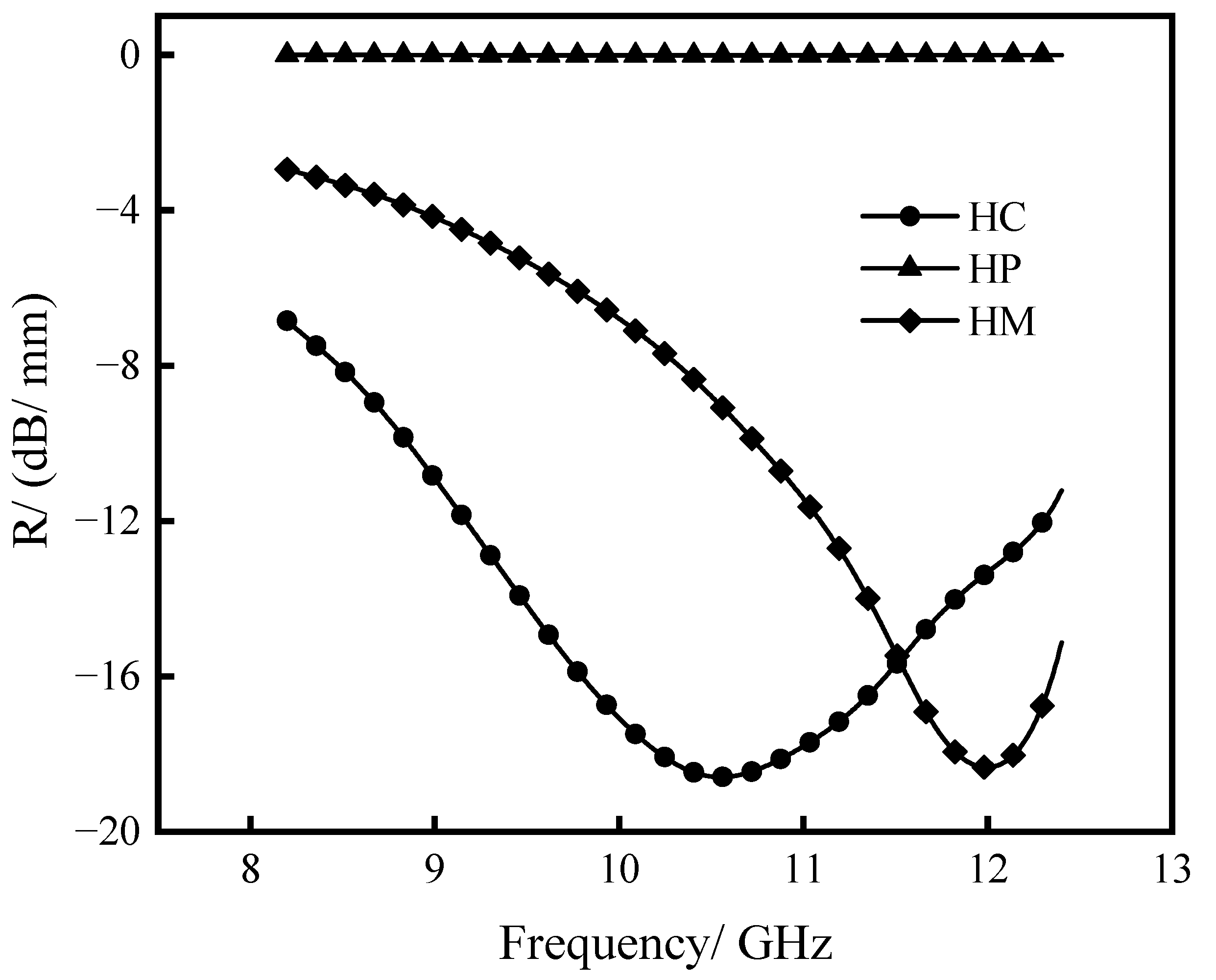
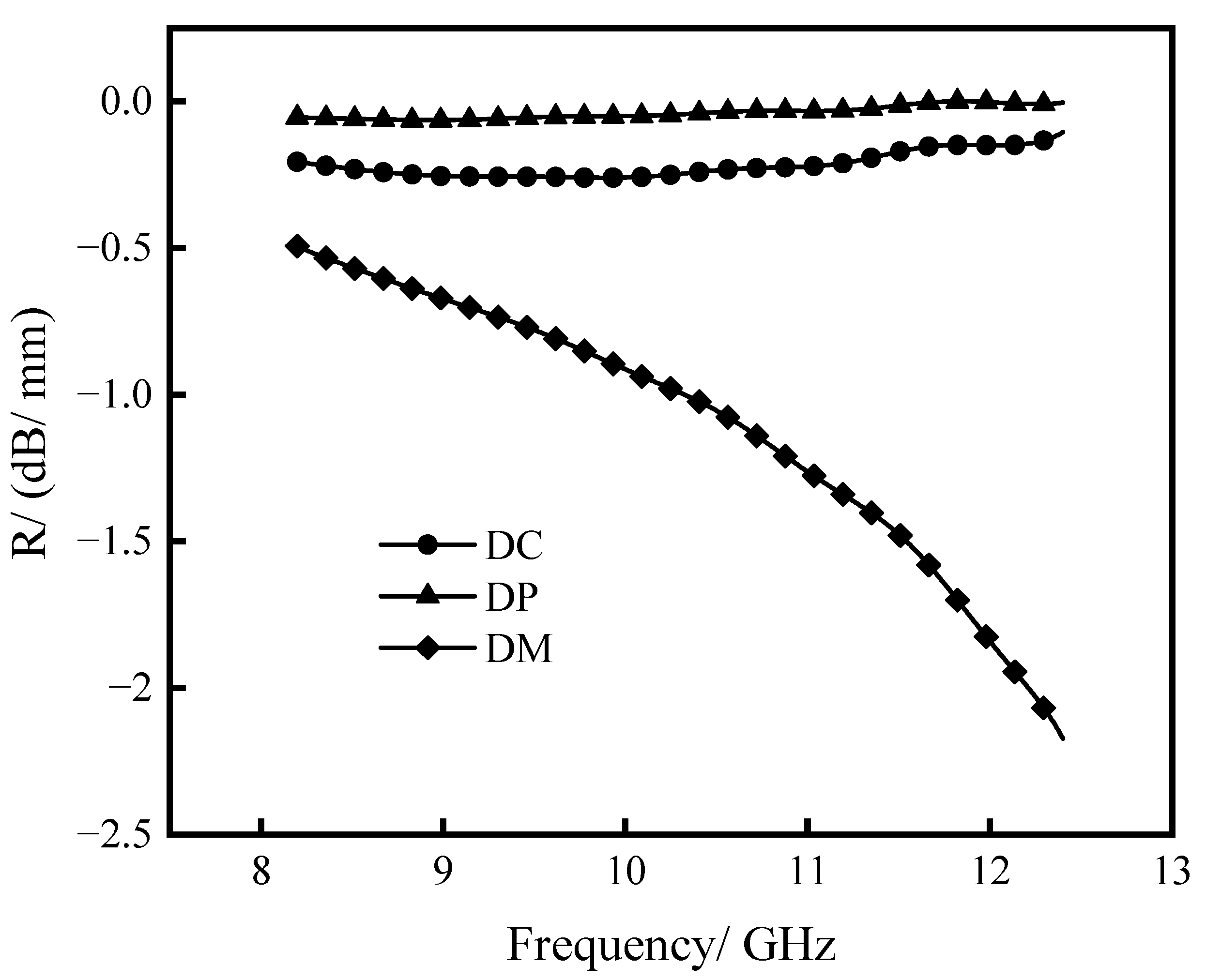
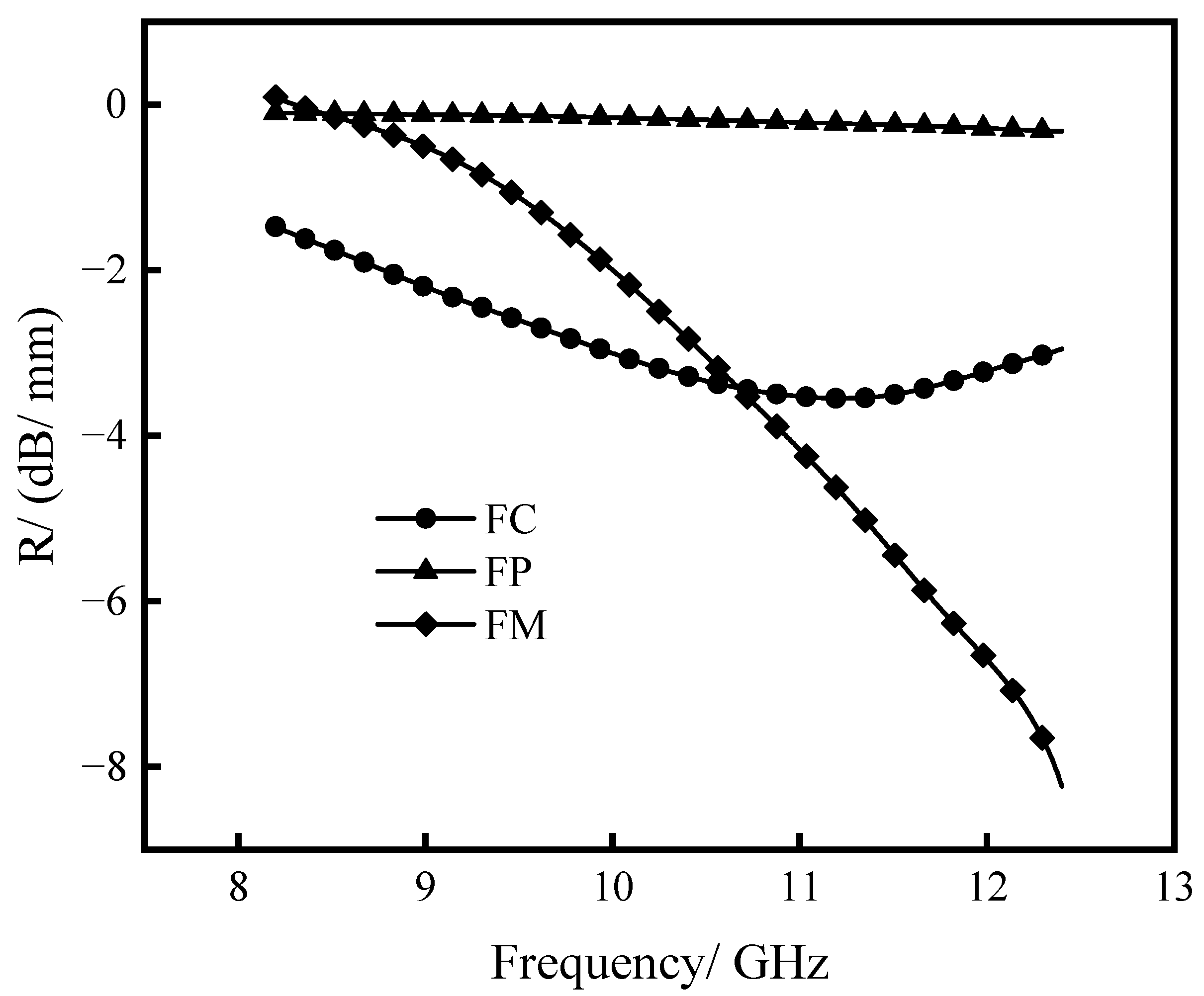
3.1.2. Absorbing Performance Test

According to the experimental design, the reflection loss per unit thickness of single-layer hot-rolled nonwovens is measured with the change of electromagnetic frequency, as shown in Figure 5.
In general, when the reflection loss is less than −10 dB, it is considered as effective absorption. The efficient frequency is the frequency band with the reflection loss no higher than −10 dB, which means that more than 90% microwave can been absorbed. Therefore, it’s useful in judging the microwave absorption performance of an absorber. It can be seen from Figure 5 that the minimum reflection loss (−18.59 dB) of HC occurs at 10.55 GHz and the efficient frequency occurs at 8.86–12.40 GHz. The minimum reflection loss (−18.34 dB) of HM occurs at 12.00 GHz, and the efficient frequency occurs at 10.75–12.40 GHz. The HP has almost no absorbing effect. This paper considers that the attenuation of magnetic loss may have more of a relationship with thickness. After the hot-rolling process, the magnetic particles attached to the fiber surface only increase the chance of reflection and will not contribute to the absorbing property. However, in the situation of HC, it can achieve effective absorption in more than 3/4 of the X-band, as the chiral characteristics and spiral structure model of CNTs will absorb electromagnetic waves of this part of the frequency [24,25]. Moreover, the minimum reflection loss of HM occurs at higher frequency than that of HC. As the magnetic loss of ferrite disappears at several GHz, it is a dielectric loss material based on HM at the higher frequencies, displaying a narrow backward reflection loss, comparing with that of HC.
The reflection loss per unit thickness of single-layer impregnated nonwovens varies with the electromagnetic frequency, as shown in Figure 6.
It can be seen from Figure 6 that the X-band reflection loss values of the single-layer impregnated nonwovens DC, DP, and DM with the thickness of 1 mm are very small, which indicates that the impregnation process cannot take good advantage of the chiral characteristics of the CNTs. The matrix of impregnated material uses polyurethane resin, which not only reduces the conductivity of impregnated material, and therefore reduces the attenuation of the alternating electric field, but also fills the voids in the fiber and reduces the secondary reflection of electromagnetic waves. Therefore, the reflection loss values of impregnated nonwovens are very small. However, in these materials, the value of DM is significantly better than that of DC and DP, as DM displays a significant decrease in X-band. It is clear that the loading of magnetic particle into a dielectric material can greatly strengthen the reflection loss in X-band. As mentioned above, the magnetic loss of ferrite disappears at several GHz; it is a dielectric loss material based on DM at the higher frequencies, displaying a narrow backward reflection loss, comparing with that of HC. This indicates that in the polyurethane resin impregnation of nonwoven material, the impedance matching performance of the mixed absorbing agent is better than that of both the dielectric absorbing agent and the magnetic absorbing agent.
To verify the influence of the polyurethane resin with different fillers’ compound system on absorbing performance, the reflection loss per unit thickness of single-layer absorbing film varies with the frequency of electromagnetic waves, as shown in Figure 7.
It can be seen from Figure 7 that the reflection loss law of single-layer absorbing film is similar to that of single-layer impregnated nonwovens, with insignificant absorption effect. For example, the lowest reflection loss of FC is about −3.5 dB. There are almost no holes in the polyurethane film, which sacrifices a lot of opportunities for secondary reflection of electromagnetic waves in the film, and reduces the absorption of electromagnetic waves by the absorbing agent. Despite this, the FM still has a band reflection loss of about 1 GHz lower than −5 dB, This suggests that, in the polyurethane film, mixed absorbing agent acvieves a good impedance matching performance.
Comparing with Figure 5, Figure 6 and Figure 7, it can be found that the order of absorbing performance, of single-layer absorbing materials made from these three different processing methods, is hot-rolled nonwovens, film, and impregnated nonwovens. This shows that the hot rolling process can fully reflect the chiral characteristics of CNTs, and the thickness of 1 mm can produce effective broadband absorption. Due to the non-Newtonian fluid characteristics of the impregnated nonwovens matrix, the uniform dispersion of the absorbing agent in the matrix and the voids of the nonwovens during the impregnation process cannot be guaranteed. Therefore, impregnated nonwovens exhibit the worst absorbing effect. Fe3O4 powder shows almost zero reflection loss in the three processing methods. In addition, when it is compounded with CNTs in a nonwoven fabric or film, it will have a significant positive impact on reflectivity. This indicates that although Fe3O4 powder cannot provide magnetic loss in X-band, it will form impedance matching when it interacts with CNTs, thereby enhancing the absorbing effect of the material. In particular, HC displays efficient RL, which is different from DC and FC, indicating the loading of CNTs in hot-rolled nonwovens strengthens the nonwoven’s reflection loss significantly.
The above experimental results indicate that the hot rolled process is preferred when preparing a single-layer wearable, flexible, absorbing material. For the wave absorbing filler, the impedance matching performance of the mixed wave absorber is better than that of the dielectric wave absorber and the magnetic wave absorber, and a mixed reagent with a ratio of CNTs and Fe3O4 of 1:1 is preferred. In addition, by increasing the thickness of the materials, the absorbing performance can be effectively improved.

3.2. Multi-Layer Absorbing Structures

3.2.1. Construction Methods

In this experiment, the prepared absorbing films can be attached to the surface of nonwoven materials or sandwiched between multi-layer nonwoven materials, so that it can be combined with other absorbing structures to form a multi-layer absorbing structure while ensuring good absorbing performance. In order to explore the influence of absorbing film and multi-layer absorbing structure on absorbing performance, two immersed hot-rolled cloths and one absorbing film form a three-layer absorbing structure, and the change of absorbing performance is explored by changing the position of the film. As shown in Figure 5, HC displays more efficient absorption frequency range than that of HM in X-band. Therefore, if HC is on the top layer, it will help the multi-layer absorb more injected waves than that of the HM. HM on the bottom layer on one hand shows a strong absorption in the range of 1.65 GHz (10.75–12.4 GHz), on the other hand, the microwave is more likely be reflected into the stacked layers, thanks to its narrow efficient absorption frequency range, which is beneficial to multiple reflection and interface loss. Therefore, the HC is always put on the upper position, and HM at the lower position. The test scheme is shown in Table 2, where letters represent the order in which the three materials are stacked from top to bottom. According to the test results, the thicknesses of the six schemes are close. Therefore, the real reflection loss can be directly measured when testing the absorbing performance.

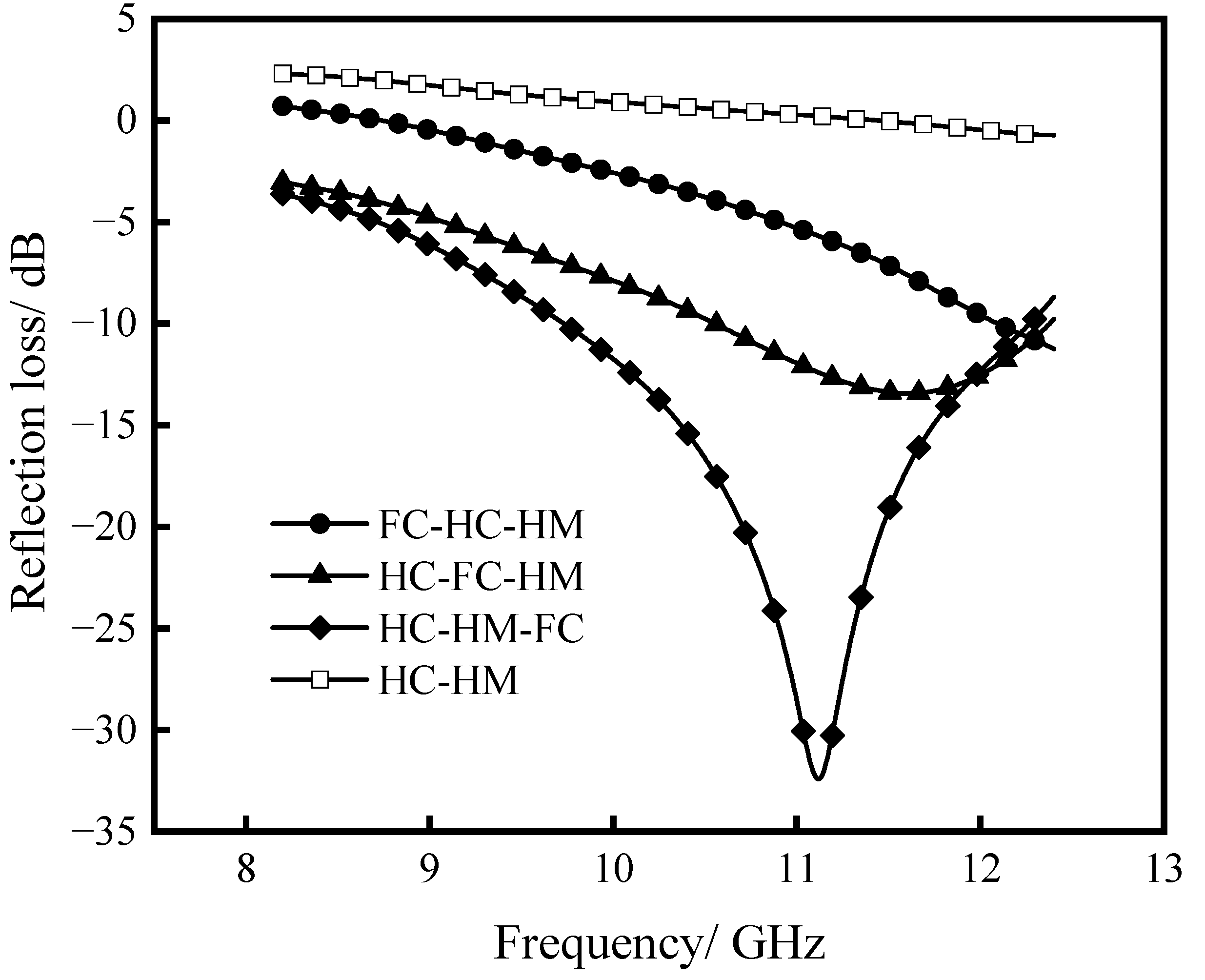
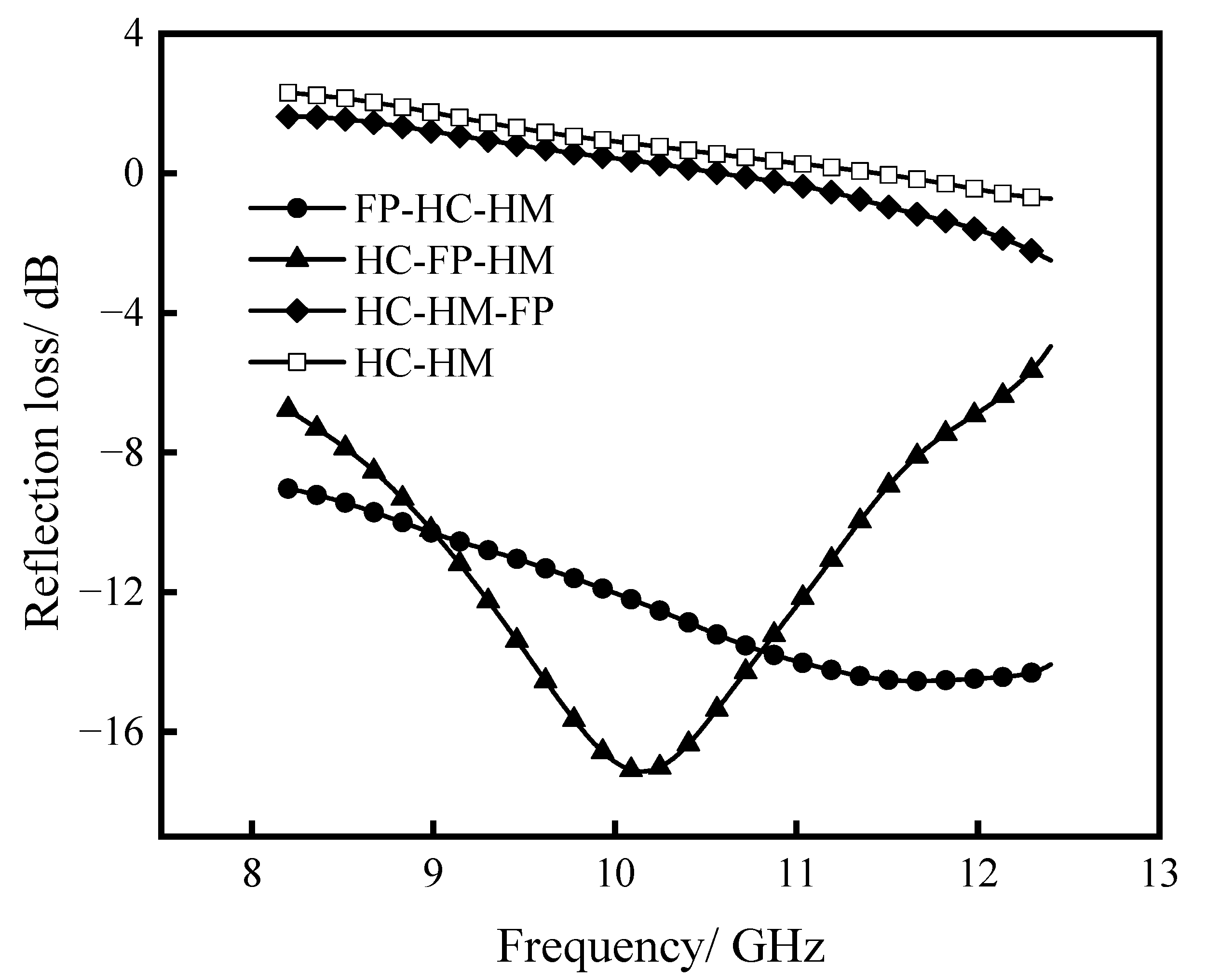
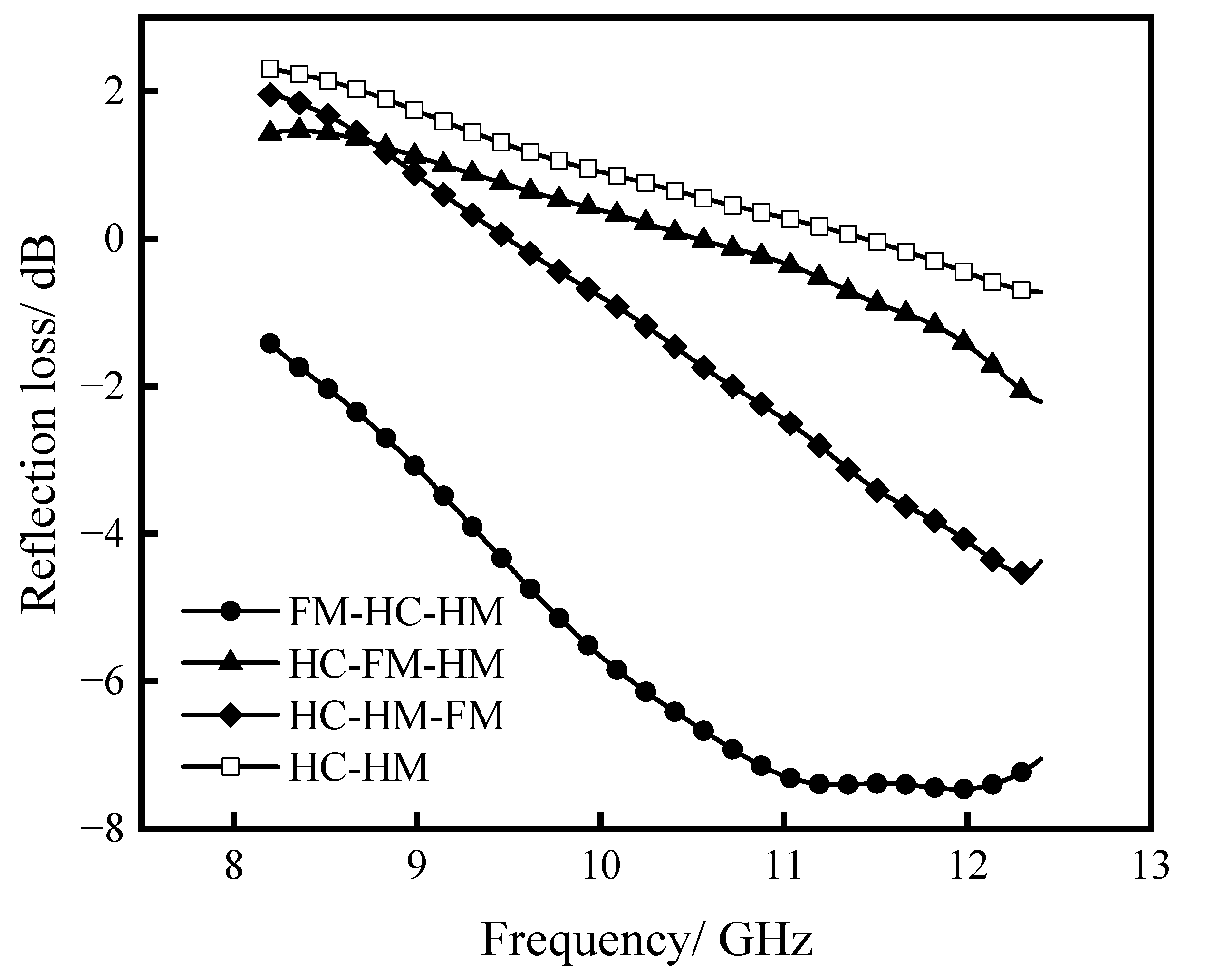
3.2.2. Influence of Film Position on Absorbing Performance

FC film is placed on the top layer, in the middle layer, and at the bottom layer of HC and HM hot-rolled cloth stacked two layers, respectively. The reflection loss of stacked three layers is measured and compared with that of the stacked two layers, as shown in Figure 8.
As can be seen from Figure 8, in the stacked two-layer, with HC on the top layer, and HM at the bottom layer, the reflection loss disappears and shows enhanced reflection. Although the two materials HC and HM have better absorbing properties separately, when the two are stacked directly, there is an impedance mismatch between the upper and lower materials due to the huge difference between the electrical and magnetic properties, thus leading to the weakened or even disappeared absorbing property.
For the stacked three-layer materials, FC film with a thickness of 0.4 mm is placed on the top, middle, and bottom of the two layers of hot-rolled cloth of HC and HM, respectively. It can be found that the reflection loss of the three-layer absorbing structure increases substantially. When the film is placed on the upper layer, the three-layer absorbing structure exhibits absorbing performance, with minimum reflection loss of −11.5 dB (f = 12.4 GHz). When the film is placed in the middle layer, the three-layer absorbing structure exhibits efficient reflection in nearly one-third of the X-band, with minimum reflection loss of −13.5 dB (f = 11.5 GHz). When the film is placed on the lower layer, the minimum reflection loss (−33 dB) occurs at 11 GHz, and the effective absorbing frequency range covers approximately half of X-band. This phenomenon is closely related to the electrical properties and structure of FC film. Through the comparative analysis of the above single-layer materials, it can be found that the attenuation ability of FC film to electromagnetic waves is less than that of HC and HM. When the FC film is placed on the upper layer, although the absorbing performance of the FC film itself is not strong, its dense structure helps to reflect electromagnetic waves back from the surface of the middle material layer, thereby the reflection loss is increased. When FC film is placed in the middle layer, the attenuation ability of the middle layer material to electromagnetic waves is much smaller than that of the upper- and lower-layer materials. It is equivalent to adding a thin layer of wave-transmitting material, which reduces the impedance mismatch. Moreover, the mirror-like flatness of FC film helps electromagnetic waves reflect on both sides of the FC film interface, which increases the attenuation path of electromagnetic waves and improves absorbing performance. When the FC film is placed at the bottom layer, more electromagnetic waves will be reflected at the FC film interface, which will increase the loss of electromagnetic waves in the HM and HC layers, resulting in a significant increase in absorption efficiency.
FP film is placed on the top layer, in the middle layer, and at the bottom layer of HC and HM hot-rolled cloth stacked two layers, respectively. The reflection loss of stacked three layers is measured and compared with that of the stacked two layers, as shown in Figure 9.
As mentioned earlier, in the stacked two-layer, with HC on the top layer, and HM at the bottom layer, the reflection loss disappears, and exhibits reflection enhancement. When the FP film is placed on the lower layer of HC and HM, it is similar to the stacked two-layer, the reflection loss shows no significant improvement. When the FP film is used as the middle and upper layers of the stacked three layers, the absorbing property is significantly improved, and almost the entire X-band can have a reflection loss of lower than −5 dB. Especially when FP film is placed on the upper layer to the HC-HM two stacked layers, effective absorption can be achieved in the frequency range of more than 3 GHz. The FP film is a kind of polyurethane film with Fe3O4 particles dispersed in it, which has the characteristics of magnetic loss medium, but does not have the characteristics of dielectric loss. Therefore, when it is placed on the lower layer of the laminated structure, it will not reflect more electromagnetic waves back into the underlying structure. Moreover, as the thickness of the FP film is small and the absorbing performance is weak, it will not have much impact on the absorbing performance. However, polyurethane film, a wave-transmitting material, has a flat surface and even structure compared to that of needle-punched material, which is composed with a great amount of disordered tangled short fibers, and therefore the pore formed. Therefore, the flat state of polyurethane film is more conducive to the transmission of electromagnetic wave. Additionally, the dispersed Fe3O4 particles with magnetic characteristics are conducive to the part of the electromagnetic wave energy loss. Furthermore, the energy reflected from below can perhaps be reflected back again when it met with the dispersed Fe3O4 particles, and the energy can be reduced again in the laminated material. As the thickness of the film is only 0.7 mm, and the size of the particles is much smaller than the wavelength, these authors believe that the main role in this part is the wave transmission property of polyurethane film and the diffuse reflection of the electromagnetic wave by Fe3O4 particles.
FM film is placed on the top layer, in the middle layer, and at the bottom layer of HC and HM hot-rolled cloth stacked two layers, respectively. The reflection loss of stacked three layers is measured and compared with that of the stacked two layers, as shown in Figure 10.
As mentioned above, the electromagnetic absorption performance of stacked two layers structure HC–HM is nearly zero, while the reflection is enhanced. When the FM film is placed between and below the HC and HM, the absorbing effect is slightly improved. Moreover, when the FM film is placed on top of the HC and HM, the absorption performance is greatly improved, which obtains a reflection loss of lower than −5 dB during about half of the frequency range of the X-band. This is as the functional phase in the FM film includes CNT and Fe3O4 particles, which have dielectric loss and magnetic loss dielectric characteristics, respectively. When the two kinds of particles are mixed and dispersed in a 0.6 mm thick polyurethane film, the dielectric loss and magnetic loss ability of the composite material will be suppressed compared to the single-functional phase of FC and FP films. Therefore, when the FM film is placed in the middle and bottom layers of the laminated structure, it has only a little effect on the absorbing performance. As polyurethane itself has wave-transmitting properties, the flat state of the polyurethane film is more conducive to the transmission of electromagnetic waves than the disordered pores formed by the disordered entanglement of the staple fibers in the non-woven fiber sheet. On one hand, the magnetic and dielectric characteristics of the mixed particles dispersed in the polyurethane film are helpful to the loss of electromagnetic wave energy. On the other hand, the energy reflected from the lower layer can also be reflected back again, and the loss will be carried out again inside the laminated material. As the thickness of the film is only 0.6mm, and the size of the particles is much smaller than the wavelength, we think that the main role in this part is the wave transmission property of polyurethane film and the diffuse reflection of electromagnetic waves by the Fe3O4 particles.
The above results show that, when preparing multilayer wearable flexible absorbing materials, it is preferable to use the HC–HM–FC structure scheme to obtain the maximum effective absorbing frequency range. By comparing Figure 8, Figure 9 and Figure 10, it can be found that the three types of absorbing films, FC, FP, and FM, all show an average absorbing performance when used separately. However, when they are used as one of the three-layer structure, they will all have a positive impact on the absorbing performance of the laminated material. The magnitude of the influence is related to its electromagnetic loss characteristics and the position in the stack layers. For example, the FC film has dielectric properties, and when it is used as the middle and bottom layers, microwaves can be effectively absorbed. The FP film is magnetic-charactered, and when it is used as the upper and middle layers, a larger effective microwave absorption range can be obtained. FM is a mixed dielectric and magnetic film, which can improve the absorbing effect to a certain extent. However, if impedance cannot match properly, the absorbing effect of FC film is much worse than FC or FP film. HC and HM, with excellent microwave absorption performance, respectively, are chosen as the other two layers of the three-layer structure. We found that the absorbing performance of HC–HM–FC is the best. It is found that HC–HM–FC has the best microwave absorption performance, which not only takes a good advantage of excellent electromagnetic absorption property of HC and HM, but also avoids the impedance mismatch of HC–HM combination. It means that by optimizing both the electromagnetic properties of the single-layer materials and their layer structures, the adverse effects of impedance mismatch on the laminated absorbing materials can be better conquered.

4. Conclusions

(1) For the single-layer absorbing structures, the hot-rolled nonwovens have the best absorbing performance, followed by absorbing films, and impregnated nonwovens are the worst. Among them, the hot-rolled nonwovens modified by CNTs has the smallest absorption loss at 10.5 GHz, which is −18.4 dB, and the effective frequency range is 10.6–12.4 GHz;
(2) The hot rolling process can fully present the chiral characteristics of CNTs, and can produce broadband effective absorption at a thickness of 1 mm. The absorbing structure prepared by using Fe3O4 powder alone has poor performance, but when it interacts with CNTs, the impedance matching will be formed, thereby enhancing the absorbing effect of the materials;
(3) When a piece of carbon nanotubes modified nonwoven with a good absorbing performance, and that of Fe3O4 powder modified nonwoven are stacked into a two-layer structure directly, the microwave absorption performance of the structure may disappear. However, the structure can regain its absorbing property by introducing the absorbing film into the two-layer structure. Both the place where the absorbing film is introduced, and the type of absorbing fillers significantly affect the properties of multilayer microwave absorbing structures;
(4) For the multi-layer absorbing structure, HC–HM–FC has the best absorbing performance. The minimum reflection loss can reach −33 dB, and the effective absorbing frequency range covers about half of the X-band. When the FP film is placed between and on the HC and HM, the absorption performance is enhanced, and almost the entire X-band can have a reflection loss below −5 dB. When the FP film is placed on top of HC and HM, the absorption performance is improved. About half of the frequency range of the X-band can reach a reflection loss of less than −5 dB;
(5) The recommendations in terms of technological optimization of the wearable flexible absorbing materials. When preparing a single-layer wearable flexible absorbing materials, the hot rolled process and the mixed reagent with a ratio of CNTs and Fe3O4 of 1:1 are preferred. When preparing multilayer wearable flexible absorbing materials, it is preferable to use the HC–HM–FC structure scheme to obtain the maximum effective absorbing frequency range.

Author Contributions

Conceptualization, W.G. and Q.G.; methodology, R.Z., Q.G. and Z.Z.; validation, J.Z.; formal analysis, J.Z.; resources, W.G. and G.Z.; writing—original draft, R.Z. and Z.Z.; writing—review and editing, W.G. and J.Z.; investigation, Q.J.; visualization, J.Z.; and supervision, W.G. All authors have read and agreed to the published version of the manuscript.

Funding

This research was funded by Jiangsu Overseas Research and Training Program for University Prominent Young and Middle-aged Teachers and Presidents (grant number 148), and the Innovative Project of Nantong University Students (grant number 143).

Data Availability Statement

Not applicable.

Acknowledgments

Sincere thanks go to anonymous reviewers for their valuable comments and great suggestions to improve this article.

Conflicts of Interest

The authors declare no conflict of interest.

References

  1. Wanasinghe, D.; Aslani, F.; Ma, G. Electromagnetic shielding properties of carbon fibre reinforced cementitious composites. Constr. Build. Mater. 2020, 260, 120439. [Google Scholar] [CrossRef]
  2. Yang, J.; Liao, X.; Wang, G.; Chen, J.; Guo, F.; Tang, W.; Wang, W.; Yan, Z.; Li, G. Gradient structure design of lightweight and flexible silicone rubber nanocomposite foam for efficient electromagnetic interference shielding. Chem. Eng. J. 2020, 390, 124589. [Google Scholar] [CrossRef]
  3. Kim, J.H.; Lee, J.K.; Kim, H.G.; Kim, K.B.; Kim, H.R. Possible effects of radiofrequency electromagnetic field exposure on central nerve system. Biomol. Ther. 2019, 27, 265. [Google Scholar] [CrossRef]
  4. Ansal, K.A.; Divya, S.J.; Roshni, K.R. Review on biological effect of electromagnetic radiation. In Proceedings of the 2018 International Conference on Circuits and Systems in Digital Enterprise Technology (ICCSDET), Kottayam, India, 21–22 December 2018; IEEE: Piscataway, NJ, USA, 2018; pp. 1–5. [Google Scholar]
  5. Li, P.; Low, A.S.; Shan, Y.Y.; Ong, G.C.; Yin, X.J. EMI Shielding Effectiveness of CNTs Composites. Appl. Mech. Mater. 2013, 331, 439–442. [Google Scholar] [CrossRef]
  6. Chen, Y.; Zhang, H.B.; Yang, Y.; Wang, M.; Cao, A.; Yu, Z.Z. High-performance epoxy nanocomposites reinforced with three-dimensional carbon nanotube sponge for electromagnetic interference shielding. Adv. Funct. Mater. 2016, 26, 447–455. [Google Scholar] [CrossRef]
  7. Liang, C.; Song, P.; Ma, A.; Shi, X.; Gu, H.; Wang, L.; Gu, J. Highly oriented three-dimensional structures of Fe3O4 decorated CNTs/reduced graphene oxide foam/epoxy nanocomposites against electromagnetic pollution. Compos. Sci. Technol. 2019, 181, 107683. [Google Scholar] [CrossRef]
  8. Zhao, L.; Zhao, T. Research on Design and Application of Absorbing Material Based on Electromagnetic Compatibility of Handheld Device; IOP Conference Series: Materials Science and Engineering; IOP Publishing: Bristol, UK, 2019; Volume 677, p. 022016. [Google Scholar]
  9. Gu, W.; Zhan, R.; Li, R.; Liu, J.; Zhang, J. Preparation and Characterization of PU/PET Matrix Gradient Composites with Microwave-Absorbing Function. Coatings 2021, 11, 982. [Google Scholar] [CrossRef]
  10. Yuan, Y.; Yin, W.; Yang, M.; Xu, F.; Zhao, X.; Li, J.; Peng, Q.; He, X.; Du, S.; Li, Y. Lightweight, flexible and strong core-shell non-woven fabrics covered by reduced graphene oxide for high-performance electromagnetic interference shielding. Carbon 2018, 130, 59–68. [Google Scholar] [CrossRef]
  11. Tiuc, A.E.; Vasile, O.; Vermesan, H. Acoustic performance of composite materials made from textile waste. RJAV 2015, 12, 111. [Google Scholar]
  12. Song, W.; Guan, X.; Fan, L.; Zhao, Y.; Cao, W.; Wang, C.; Cao, M. Strong and thermostable polymeric graphene/silica textile for lightweight practical microwave absorption composites. Carbon 2016, 100, 109–117. [Google Scholar] [CrossRef] [Green Version]
  13. Bi, S.; Tang, J.; Wang, D.J.; Su, Z.A.; Hou, G.L.; Li, H.; Li, J. Lightweight non-woven fabric graphene aerogel composite matrices for assembling carbonyl iron as flexible microwave absorbing textiles. J. Mater. Sci. Mater. Electron. 2019, 30, 17137–17144. [Google Scholar] [CrossRef]
  14. Egami, Y.; Yamamoto, T.; Suzuki, K.; Yasuhara, T.; Higuchi, E.; Inoue, H. Stacked polypyrrole-coated non-woven fabric sheets for absorbing electromagnetic waves with extremely high frequencies. J. Mater. Sci. 2012, 47, 382–390. [Google Scholar] [CrossRef]
  15. Liu, Y.; Liu, Y.; Zhao, X. The research of EM wave absorbing properties of ferrite/silicon carbide double coated polyester woven fabric. J. Text. Inst. 2018, 109, 106–112. [Google Scholar] [CrossRef]
  16. Shi, Y.; Yu, L.; Li, K.; Li, S.; Dong, Y.; Zhu, Y.; Fu, Y.; Meng, F. Well-matched impedance of poly pyrrole-loaded cotton non-woven fabric/polydimethylsiloxane composite for extraordinary microwave absorption. Compos. Sci. Technol. 2020, 197, 108246. [Google Scholar] [CrossRef]
  17. Ren, W.; Zhu, H.; Yang, Y.; Chen, Y.; Duan, H.; Zhao, G.; Liu, Y. Flexible and robust silver coated non-woven fabric reinforced waterborne polyurethane films for ultra-efficient electromagnetic shielding. Compos. Part B Eng. 2020, 184, 107745. [Google Scholar] [CrossRef]
  18. Tan, Y.J.; Li, J.; Gao, Y.; Guo, S.; Wang, M. A facile approach to fabricating silver-coated cotton fiber non-woven fabrics for ultrahigh electromagnetic interference shielding. Appl. Surf. Sci. 2018, 458, 236–244. [Google Scholar] [CrossRef]
  19. GB/T3820-1997. Determination of Thickness of Textiles and Textile Products; The Standalization Institute of China National Textile Council: Beijing, China, 1997. (In Chinese) [Google Scholar]
  20. GJB 2038A-2011. The Measurement Methods for Reflectivity of Radar Absorbing Material; Chinese People’s Liberation Army General Armament Department: Beijing, China, 2011. (In Chinese) [Google Scholar]
  21. Wazna, E.M.; Mrajji, O.; Ouhaibi, S.; Garoum, M.; Belouaggadia, N.; Omar, C.; Bouari, A.E. Polyurethane Coated Non-Woven: A Promising Solution for Building Insulation; IOP Conference Series: Materials Science and Engineering; IOP Publishing: Bristol, UK, 2020; Volume 827, p. 012039. [Google Scholar]
  22. Zhu, J.; Yudasaka, M.; Zhang, M.; Sumio, I. Dispersing carbon nanotubes in water: A noncovalent and nonorganic way. Indian J. Chem. B 2004, 108, 11317–11320. [Google Scholar] [CrossRef]
  23. Zhu, W.; Li, Y.; Dai, L.; Li, J.; Li, X.; Li, W.; Duan, T.; Lei, J.; Chen, T. Bioassembly of fungal hyphae/carbon nanotubes composite as a versatile adsorbent for water pollution control. Chem. Eng. J. 2018, 339, 214–222. [Google Scholar] [CrossRef]
  24. Iijima, S. Helical microtubules of graphitic carbon. Nature 1991, 354, 56–58. [Google Scholar] [CrossRef]
  25. Pielmeier, M.R.P.; Karttunen, A.J.; Nilges, T. Toward Atomic-Scale Inorganic Double Helices via Carbon Nanotube Matrices—Induction of Chirality to Carbon Nanotubes. J. Phys. Chem. C 2020, 124, 13338–13347. [Google Scholar] [CrossRef]
Figure 1. Schematic illustration of setup for evaluating reflection loss.
Crystals 11 01000 g001
Figure 2. Processes of samples’ preparation.
Crystals 11 01000 g002
Figure 3. The pictures of the samples.
Crystals 11 01000 g003
Figure 4. Differences between the actual thickness of different absorbing structures and the original target thickness.
Crystals 11 01000 g004
Figure 5. Comparison of reflection loss of single-layer hot-rolled nonwovens.
Crystals 11 01000 g005
Figure 6. Comparison of reflection loss of single-layer impregnated nonwovens.
Crystals 11 01000 g006
Figure 7. Comparison of reflection loss of single-layer absorbing film.
Crystals 11 01000 g007
Figure 8. Comparison of reflection loss of FC film at different positions in three-layer absorbing structure.
Crystals 11 01000 g008
Figure 9. Comparison of reflection loss of FP film at different positions in three-layer absorbing structure.
Crystals 11 01000 g009
Figure 10. Comparison of reflection loss of FP film at different positions in three-layer absorbing structure.
Crystals 11 01000 g010
Table 1. Preparation scheme of absorbing structure sample.
Code NameProcessing MethodAbsorbing Agent
HCHot rolledCNTs
HPHot rolledFe3O4 Powder
HMHot rolledMixed reagent
DCDippingCNTs
DHDippingFe3O4 Powder
DMDippingMixed reagent
FCFilm formingCNTs
FPFilm formingFe3O4 Powder
FMFilm formingMixed reagent
Table 2. Construction scheme of multi-layer absorbing structures.
Test Program CodeThickness (mm)Absorbing Agent (Filler)Film Position
FC-HC-HM2.3CNTsUp
HC-FC-HM2.3CNTsMiddle
HC-HM-FC2.3CNTsDown
FP-HC-HM2.6Fe3O4 PowderUp
HC-FP-HM2.6Fe3O4 PowderMiddle
HC-HM-FP2.6Fe3O4 PowderDown
FM-HC-HM2.5Mixed agentUp
HC-FM-HM2.5Mixed agentMiddle
HC-HM-FM2.5Mixed agentDown
Publisher’s Note: MDPI stays neutral with regard to jurisdictional claims in published maps and institutional affiliations.

