Article

Synthesis of Thermally Stable h-BN-CNT Hetero-Structures via Microwave Heating of Ethylene under Nickel, Iron, and Silver Catalysts

1
Department of Physics, Bauchi State University Gadau, PMB 65, Gadau, Bauchi 740001, Nigeria
2
Department of Physics, Federal University Dutse, Gida Sitin, Dutse 720101, Nigeria
3
Centre for Applied Physics and Radiation Technologies, School of Engineering and Technology, Sunway University, Petaling Jaya 47500, Selangor, Malaysia
4
Department of Physics, University of Azad Jammu and Kashmir, Muzaffarabad 13100, Pakistan
5
Department of Radiological Sciences, College of Applied Medical Sciences, Taif University, Taif 21944, Saudi Arabia
*
Author to whom correspondence should be addressed.
Submission received: 13 August 2021 / Revised: 4 September 2021 / Accepted: 7 September 2021 / Published: 9 September 2021

Abstract

:
Initially, three samples of carbon nanotubes (SWCNTs) were synthesized from neem tree material. Afterward, these samples were coated with hexagonal boron nitride (h-BN) to form h-BN and CNT composite (h-BN-CNT). The essence of using h-BN (being a perfect insulator) with armchair SWCNT (being a conductor) is to create an interface between an insulator and conductor. The samples were treated under three different transition metal nanoparticles; silver, iron, and nickel. Thermogravimetric (TGA) analysis reveals that h-BN/CNT is thermally more stable with silver than iron and nickel nanoparticles. TGA profile showed resistance to mass loss at the beginning due to the higher thermal resistivity by the impurity compounds. The DFT calculation, generalized gradient approximation (GGA), and Perdew–Burke–Ernzerhof (PBE) analysis found engineered bandgap energy of 3.4 eV for the synthesized h-BN-CNT heterostructure. Because of its unique structural and electronic properties such as tunable bandgaps, the h-BN-CNT heterostructure may open new ways for manipulating excitons in the CNTs, and thus can be explored to develop various new electronic devices.

1. Introduction

In 1991, carbon nanotubes (CNTs) were discovered by Iijima [1]. Until then this had gained much attention because of its unique mechanical [2,3], electrical [4], and thermal properties [5]. It has a wide range of potential applications in the field of polymer, composites, hydrogen storage media, biomedical sciences, and field emission dipoles, etc. Although CNTs show unique structural and physical properties, they still require further improvement to be used in certain fields of nanotechnology [6]. Carbon nanotubes heterostructures are one of the most interesting areas where scientists are trying to explore novel properties and applications of CNTs. CNTs composites such as carbon nanotube metal matrix composites (CNT-MMC) are formed to make alloys due to the CNT’s high tensile strength and electrical conductivity. Cooper/carbon nanocomposites are produced to fill the high demand for copper substitutes [7]. CNT composites are used as a reinforcement and thermal reservoirs. The high demand for semiconductor devices today has led us to develop the idea of doping SWCNT with an impurity of hexagonal boron nitride (h-BN) to form a CNT hetero-structure. h-BN has an identical hexagonal structure with that of graphite. However, h-BN is an insulator or wide bandgap semiconductor whereas armchair SWCNT is a conductor in its pure form. Therefore, doping with h-BN will create an energy bandgap in CNT which will reduce its electrical conductivity to the level of semiconductors. Just like CNTs, h-BN is thermally and chemically inert known for its anisotropic behavior [8]. It is an insulator with a wide bandgap of 5.9 eV. It is an isomorph of graphene. Generally, armchair SWCNTs are rarely used as pure semiconductors because of compatibility problems that arose from their hexagonal structure and their isotropic nature. SWCNTs are used as semiconductors when they are fabricated in an impure form where the intrinsic impurities result in the creation of a bandgap that reduces and/or tries to terminate the full electrical behavior of the nanotubes. Successful doping in CNT can only be achieved when a doping material of the same structural properties such as crystallographic nature (hexagonal structure), anisotropy, piezoelectricity, pyroelectricity, and biocompatibility are used. For example, ZnO is a semiconductor with a hexagonal atomic arrangement where the oxygen is doped to a Zn to form hexagonal and a wide bandgap semiconducting material with a lattice constant of 5.2069 Å [9,10]. A successful attempt was made to create a bandgap in CNT with the optimized structure of bilayered tin selenide (SnSe) [11] using the Quantum Espresso Package. Tin selenide (SnSe) has a hexagonal honeycomb structure similar to graphene with a separation between Sn and Se atoms of 1.56 Å. The result was the creation of a SnSe-CNT semiconductor with a narrow bandgap of 2.56 eV. The PBE type of GGA exchange-correlation was used to obtain the said result. Following the same strategy, as demonstrated in reference [12]. An experimental attempt has been made in this research to create a bandgap similar to reference [13] by doping another hexagonal bilayered material (hexagonal boron nitride, h-BN) with SWCNT. Consequently, this work synthesized a new member of the 2-D family, h-BN-CNT hetero-structures via microwave heating of ethylene under the nickel, iron, and cobalt catalysts for the development of various electronic devices. The h-BN sheets (with boron and nitrogen atoms bonding) and the compatible simulation on how it forms h-BN nanotubes when interfaced with CNT are shown in Figure 1.

2. Materials and Methods

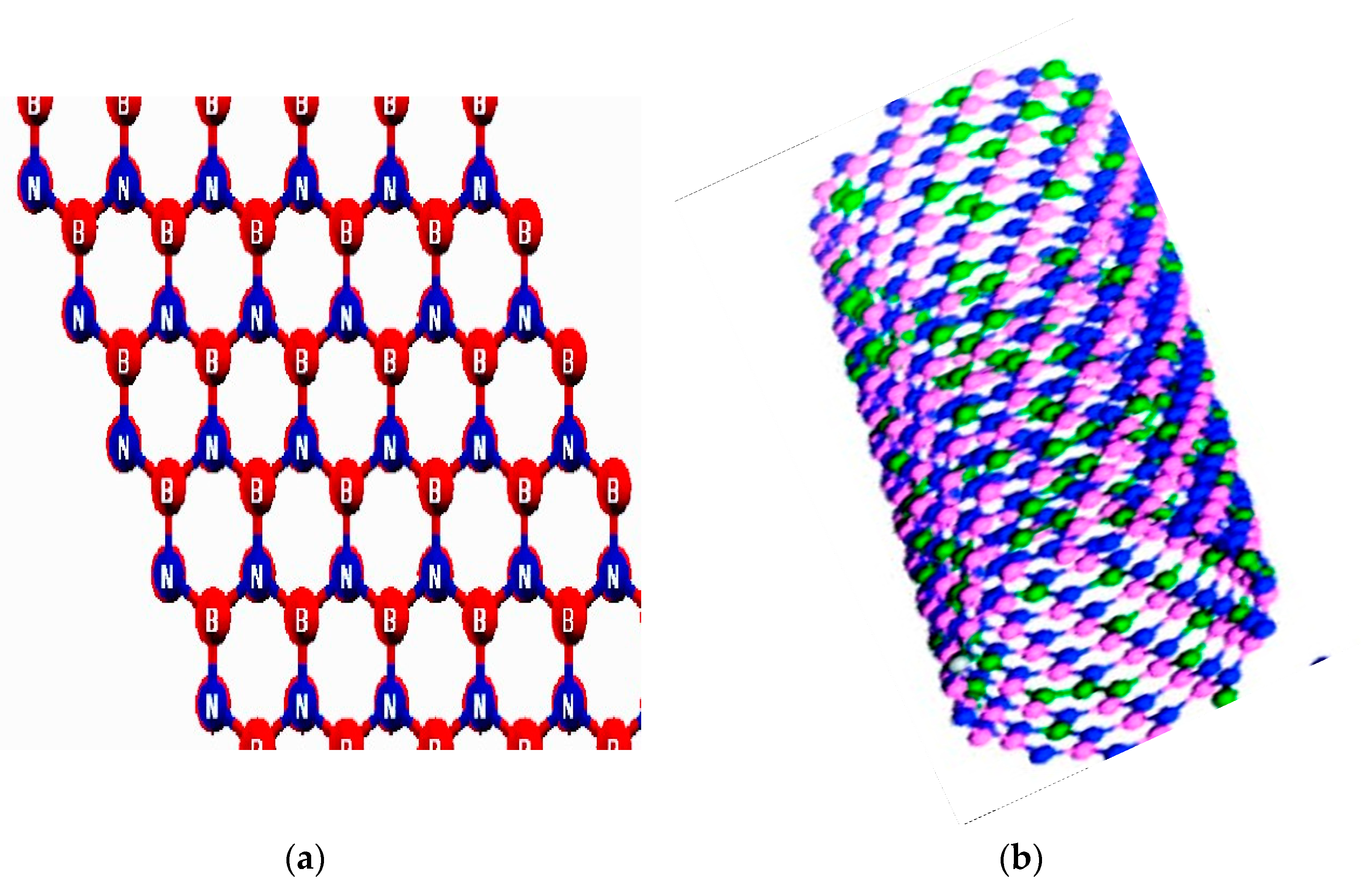
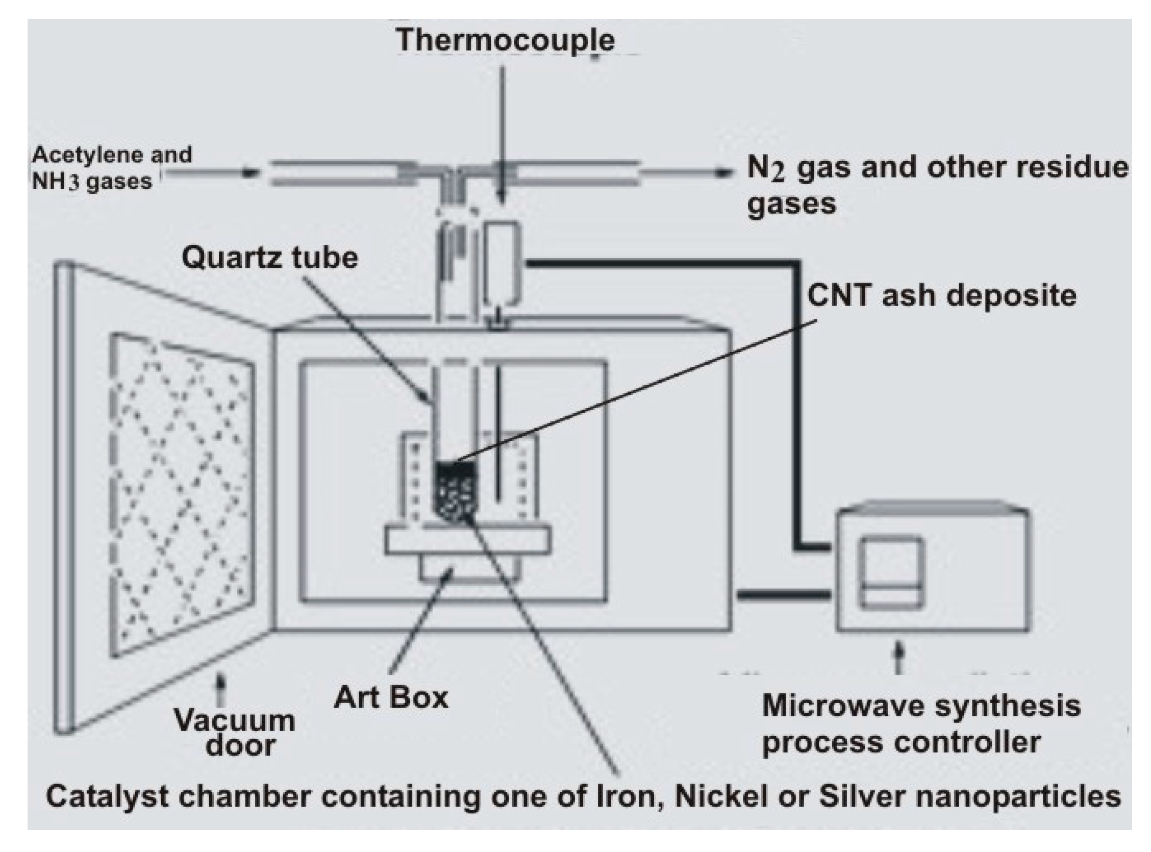
2.1. Synthesis of CNT and h-BN-CNT Composite

SWCNTs were synthesized in a microwave oven with neem bark samples in powder form taken from Itas, Bauchi State in north-eastern Nigeria. Iron, silver, and nickel nanoparticles catalysts were used in the synthesis process. Three samples were prepared and synthesized each with 20% of one of the catalysts under the same conditions. The essence of these nanoparticles was to speed up the reaction and help to remove all the metal oxides that may contaminate the as-synthesized CNT. Literature shows [14] that that acetylene is a perfect producer of CNTs, thus the spectroscopy study was skipped. The sample of the high purity h-BN was purchased from Jiangxi Nutpool Industrial Co. Ltd., China.
In the same laboratory, the sample of the hexagonal boron nitride (h-BN) coated carbon nanotubes in bulk form have been prepared via the same catalytic concentrations. SWCNTs of average diameter 15 nm and 15 µm in length are coated with h-BN and heated in an argon condition at 300 °C for 30 min. Figure 2 shows the sketch of the experimental setup.
NH3/Ar and B2O3 were used to remove some residues of oxide [15]. The washed samples were then dried at 80 °C. The reaction temperature was 300 °C. Argon was used because chemically inert materials prevent all other unwanted reactions during the synthesis.

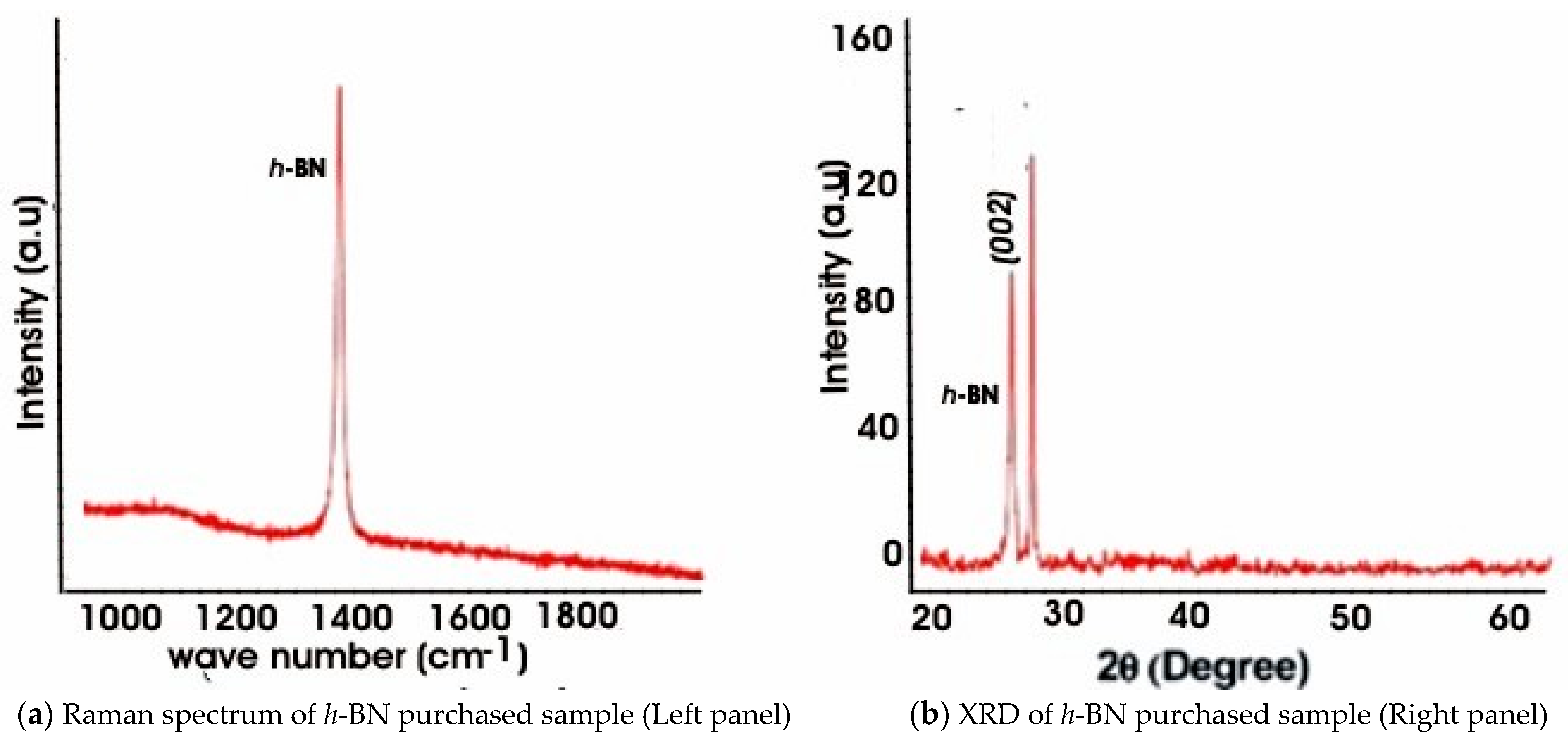
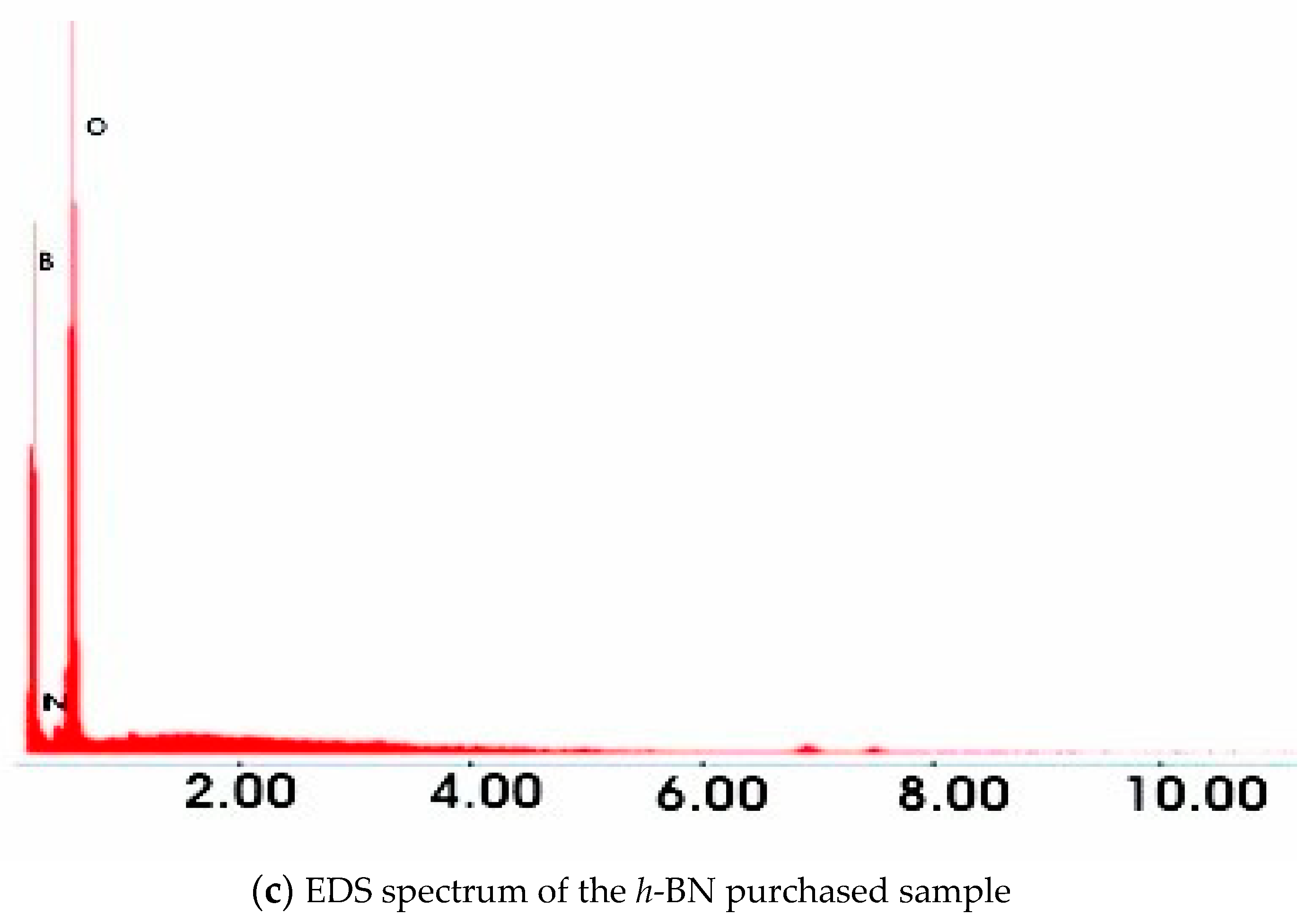
2.2. Characterization Method

The confirmatory test on the structural morphology of the CNTs was investigated in the Material Science Laboratory, Center for High Rate Nano manufacturing (CHN), at the North Eastern University, Shenyang, China. Similarly, the confirmatory test on the structural morphology of the purchased h-BN was investigated in the same laboratory. In order to further confirm the h-BN sample, we further conducted Raman, XRD, and EDS analysis as shown in Figure 3.
The Raman spectrum of Figure 3a shows a high-intensity peak at 1362 cm−1 which identifies the 2G vibrational fingerprint known for h-BN characteristics. The XRD pattern in Figure 3b demonstrates a high peak at 27.00 and also at 28.30 respectively. The peak at 27.00 can be identified as (002) h-BN phase form. The peak at 28.30 appears to be that of Boron Oxide (B2O3) presence in the purchased sample. Therefore, we cannot overrule the possibility of boron oxide presence in the sample. The presence of individual boron and nitrogen elements were shown in the EDS spectrum of Figure 3c. Oxygen peak was also seen in the EDS which comes from the manufacturer’s way of synthesis especially when metal oxide was used as substrate.
We have also conducted Raman spectroscopy of the synthesized SWCNT to study its quality through SP2 and SP3 carbon hybridization Figure 4. Strong G-bands were shown at approximately 1585, 1587, and 1588 cm−1 for iron, silver, and nickel catalysts, respectively. This range of G-band corresponds to the characteristic ordered graphitic structure due to tangential atomic vibrations. Slight vibration can be seen around 1315 due to the presence of some impurities such as amorphous carbon and other symmetry-breaking defects.
The morphological study of the synthesized sample of h-BN-CNT is done by scanning electron microscopy (SEM: JSE-6500F) and then followed by the thermogravimetric analysis (TGA) [16]. The TGA was performed to determine the purity and effect of each catalyst in the synthesis of the CNTs. Figure 5 shows the SEM micrographs of the CNTs Figure 5a, and the h-BN coated CNTs Figure 5b. It can be seen that the h-BN-CNT in Figure 5b is rough and scraggy and also thicker than the CNTs micrograph of Figure 5a.
We have used the TEM technique for morphological, structural, and confirmatory studies. TGA was used for thermal stability and purity studies and then Raman SP was used to study the material’s fingerprint.

2.3. Measurement of Bandgap Energy of the h-BN-CNT Composite

The bandgap of the h-BN-CNT hetero-combination was calculated by varying its interlayer spacing (IS). We have chosen the range of 1 to 5.0 Å interlayer spacing (IS). Table 1 shows the result obtained by using only one symmetry point (SP).
It can be seen that there is a sharp drop of the band energy from 3.76 to 1.81 eV between 1 to 1.5 Å. There is also weak bonding when the interlayer distance is large. Small interlayer distance is found to make a strong bond which overcomes Van da Waal’s bond. Also, the values band gaps from 1.0 to 2.5 interlayer spacing fall within the range of band gaps obtained from the experimental analysis. Table 2 shows the range of band gaps of h-BN heterostructures obtained from the experimental analysis reported in the literature.
The data for band gaps of h-BN hetero-combination is limited because the electrical properties of h-BN-CNT semiconductors have not been reported yet.

2.4. DFT Calculations of Bandgap Energy

The Quantum Espresso (QE) is a free and open-source computer code software under GNU general public license (GPL) for materials modeling and electronic structure calculations. It works based on the density-functional theory (DFT), plane waves, and pseudopotentials to model the interaction between valence electron and ionic core potential. In this work Quantum Espresso pseudopotential is used to perform the computational analysis. Quantum Espresso is preferred because it is one of the accurate and efficient computational codes. The studies of the band gaps for CNTs and the h-BN-CNT composite were done after the thermogravimetry. The calculated electronic properties of the synthesized CNTs and h-BN-CNT composites were computed within PBE approximation based on DFT and GW within G0W0 approximation. We do not know the exact function for the exchange-correlation, because the DFT explains that the exact exchange energy correlation functional is only known for free gas. Therefore, we used the LDA equation to arrive at the optimized absorption energy value. The LDA equation according to DTF is:
E X C L D A [ n ] =   ε X C ( n ) n ( r ) d 3 r
In the case of h-BN-CNT heterocombination, we consider the electron density ρ to take part only in the exchange-correlation. The LDA equation becomes:
E X C L D A ( n ( r ) ) =   [ ρ ( r )   ε X C H o m ( ρ ( r ) ) ] d 3 r
We have ignored the exchange-correlation due to the heterogeneities of the electrons in h-BN-CNT. The exchange-correlation energy at point r is assumed to be equal to the exchange-correlation energy of a homogeneous electron gas that has the same density at point r. Thus, one can write:
E X C L D A ( ρ ( r ) ) =   [ ρ ( r )   ε X C H o m ( ρ ( r ) ) ] d r
where ε X C H o m ( ρ ( r ) ) is the exchange-correlation energy density of an interacting homogeneous electron gas at the density   ρ ( r ) and r is the position vector. ε X C H o m ( ρ ( r ) ) is a function of the local density that can be separated into the function of exchange ε X ( ρ ( r ) ) and correlation ε C ( ρ ( r ) )
ε X C H o m ( ρ ( r ) ) = ε X ( ρ ( r ) ) + ε C ( ρ ( r ) )
The exchange energy part in LDA is known analytically from
ε X ( ρ ( r ) ) = 3 4 ( 3 π ) 1 / 3   ρ ( r ) 4 / 3 d r hence only the correlation energy part is obtained by approximation of the correlation functional.
By separating the exchange-correlation energy into the exchange part and correlation part, we have:
E X C = E X + E C
The equation used for computing the binding energy in this experiment based on Equation (5) can be written as:
Binding   energy = E h BN / CNT ( E CNT + E h BN )
The microscopic dielectric function ε ( ω ) for optical analysis is obtained by random phase approximation:
ε ( ω ) =   ε 1 ( ω ) + i   ε 2 ( ω )
G0W0 approximation is used in this work to produce a reliable and more accurate energy gap. For band structure calculations the selected high-symmetry points are K(1/3,2/3,0), Γ(0,0,0) and M(0,1/2,0) respectively.
The thermogravimetry forms the experimental basis while the DTF exchange-correlation approach provides the optimized bandgap from the theoretical/computational part. The studies of the energy convergence for CNT and h-BN were not carried out because the exact exchange-correlation functional is not known.

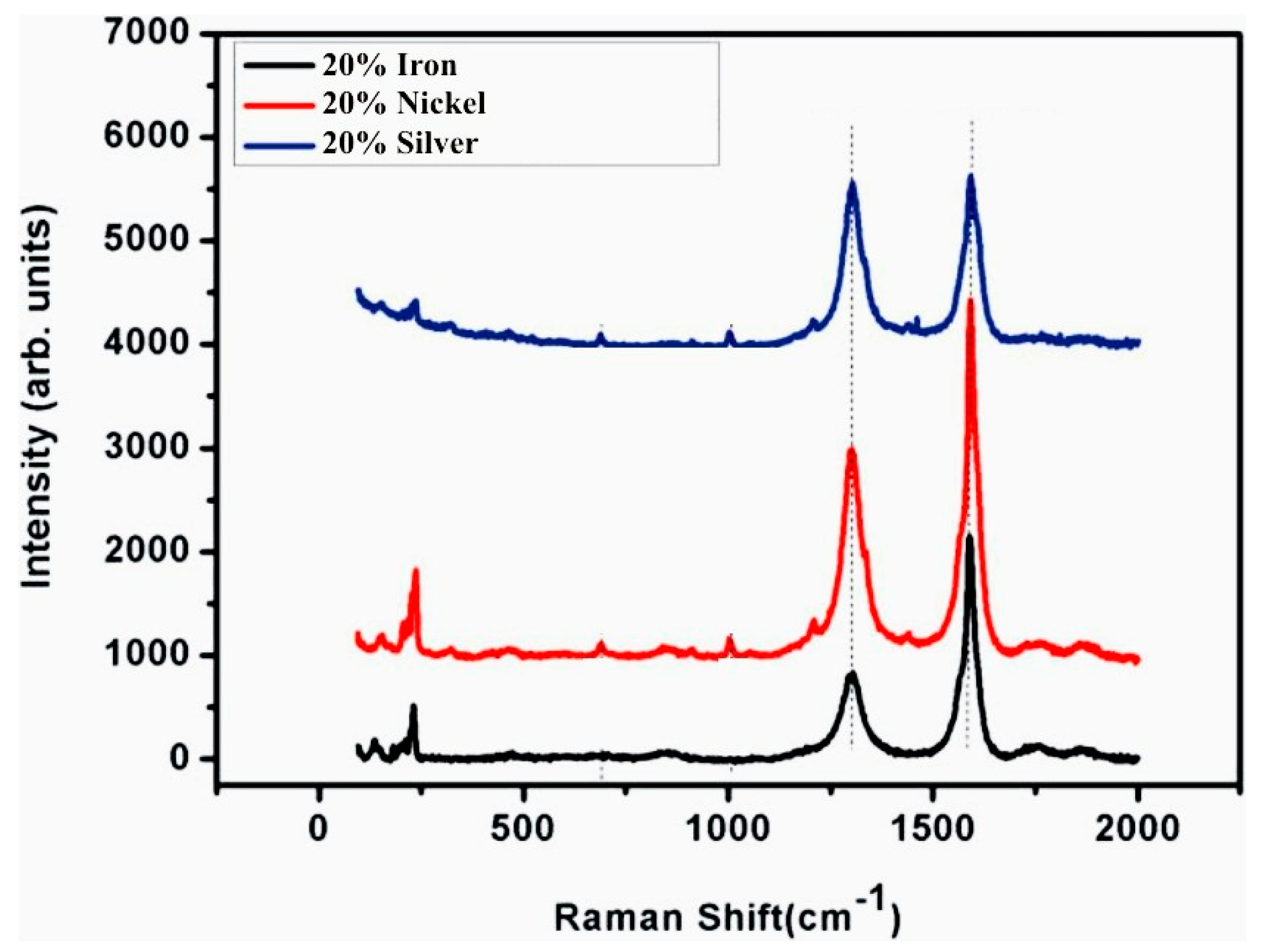
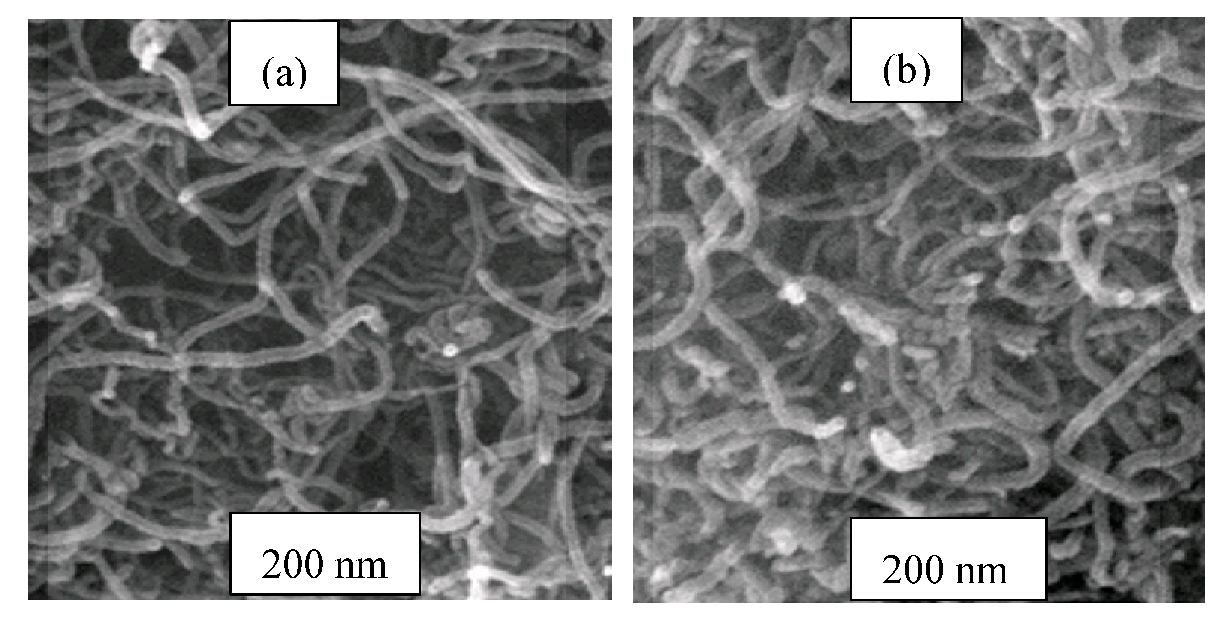
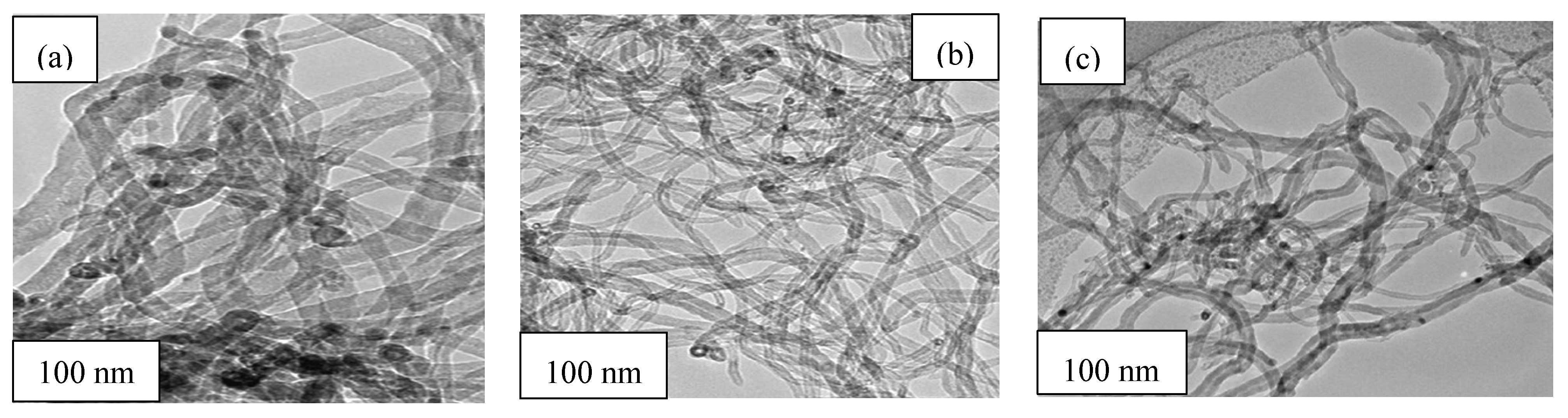
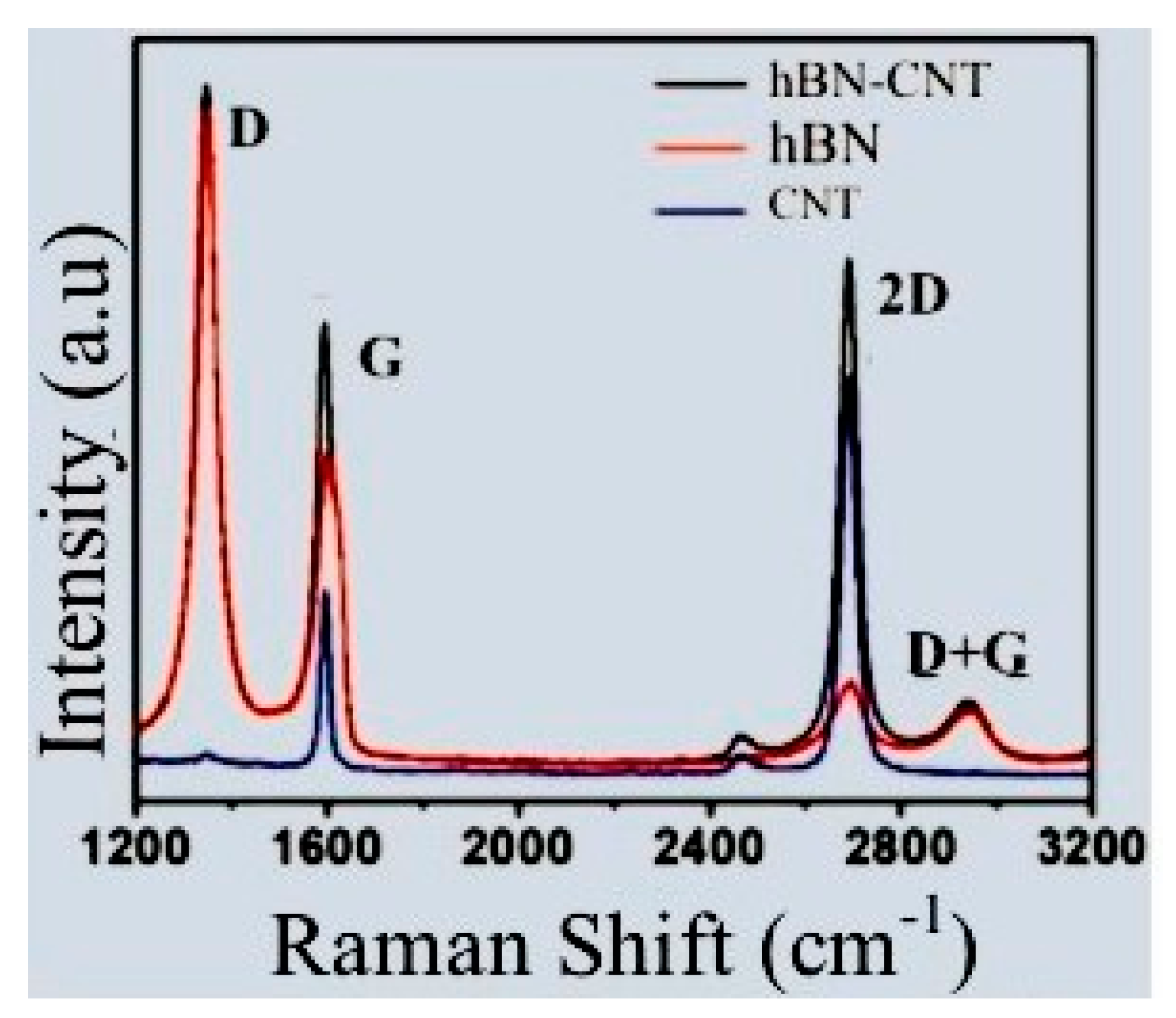
3. Results and Discussion

This section presents the detailed findings of the thermal and electrical properties of the h-BN and CNT interface via thermogravimetry and energy bandgap analysis (by DTF exchange-correlation approach). The CNT sample was prepared via microwave heating of ethylene extracted from the neem tree. The samples of CNTs with a diameter range between 4.5 to 23 nm were seen from the SEM image obtained as seen in Figure 6a. Three samples of CNTs were all doped with 15 wt% of hexagonal boron nitride to form an h-BN-CNT interface. The samples were treated separately with three different catalyst nanoparticles: silver, nickel, and iron, each of 20%.
In each case, the as-grown h-CNT was found to be between 10 to 30 nm in diameter as indicated by the TEM analysis and tens of microns in length across all samples. The scraggy nature of the nanotubes can be seen due to the presence of h-BN around the SWCNT. The sample was not purified during the synthesis process because the TGA profile had been used to detect the purity of the sample as shown. The mass-loss profile, thermogravimetric oxidation, and morphology were all analyzed. The TEM (JEM-Z200FSC) profile in Figure 6 shows three different h-BN-CNTs samples under three different catalysts. The h-BN-CNT sample with 20% silver is smoother less impure than the other two samples containing iron and nickel in the same concentrations. The Raman spectrum shown in Figure 7 is used to understand the full characteristic of the h-BN-CNT nanocomposite materials.
Figure 7 shows the regions of the h-BN-CNT defined by Raman spectra via the D, G, 2D, and D+G bands as the fingerprint of the synthesized hetero-structure. The Raman spectrum is similar to that of a CNT (as a high-intensity D band peak of 1345 cm−1) because both of their spectra are characterized by the dependence of the position of the Raman-active wave number ranges as a function of the encapsulated tube diameter [20]. This transformation can be attributed to the similar thermodynamic profiles of the two nanomaterials. h-BN transforms to boron nitride nanotube (BNNT) at a high temperature just like graphene turns to CNTs at high temperatures [21,22].
The characterization of the 2D/G ratio (approx. 3) revealed the crystalline nature of the CNT. There is also a broad G peak and also D+G peaks at 1593 cm−1 and 2940 cm−1 respectively.
The TGA profile of the three samples of the synthesized SWCNT is shown in Figure 8. As shown, there is a little loss of mass at the initial thermogravimetric stage by all samples. This happened due to the presence of impurities such as amorphous carbon with a relatively high boiling point lower than the purity temperature of the as-synthesized SWCNT sample. The sharp drop of mass by all samples between 670–683 °C demonstrates the quasi-purity stage of the synthesized SWCNT. The sample with nickel, however, showed more response to the loss of mass at the beginning compared to the other two samples. About 35–40% of the sample remain and become thermally stable with the silver catalyst becoming first to be stable at 670 °C leaving 38% of pure CNT. The sample with nickel catalyst is thermally stable at 680 °C leaving only 35% of the CNT. As can be seen, all the samples are thermally stable between the range of 670–720 °C and the results obtained with this TGA agrees well with the literature TGA of SWCNT. A significant change was observed in Figure 8b when the sample of SWCNT was coated with h-BN and treated under the same catalytic conditions. A non-steady weight loss of the sample can be observed with nickel which is attributed to the high amount of impurity oxides formed by nickel catalyst during the coating process. There is almost uniform but slow weight loss with silver compared to iron and nickel. This is because silver does not easily corrode like other transition metals. There is typically the highest stability with 20% silver nanoparticles, while lower stability is recorded by 20% nickel nanoparticles. There is a slight difference in stability in temperature of h-BN-CNT when iron and nickel were used in the same concentrations (20% in each case). This is due to the similarities in iron and nickel of their corrosion kinetics properties in acidic HNO3 solution, (corrosion potential for Iron is 4.5 while that of nickel is 5.0) [18]. It shall be noted that the sample with silver is only used in the calculation of the bandgap in this experiment. This is because high thermal stability is achieved with silver. Further experiments to study the band gap of h-BN-CNT with iron and Nickel therefore recommended.
As shown in Figure 9 there is a significant change in the thermal behavior between the synthesized SWCNT and the coated h-BN-CNT materials. Five TG points have been chosen at random to explain this. At point “A” for example, when the temperature reaches 200 °C, 90%, 92%, and 95% of the samples remain for Silver, Iron, and Nickel respectively. However, it can be seen from Figure 9b that at this same temperature 98%, 95%, and 96% remained for silver, iron and nickel, respectively. At point “B” which is 300 °C, 92%, 91%, and 90% of the sample remain with silver, iron, and nickel respectively. Similarly, at “B” with the same temperature, 96% remain with silver while 91% remain with both Iron and Nickel. As can be observed in Figure 9a,b, thermal stability is always achieved first with silver. Higher values for h-BN-CNT composites indicate that the composite material is more thermally stable than the synthesized SWCNT and this agrees well with the literature.
Armchair CNTs being a hybrid of graphene, are purely conductors under stable conditions. This is because of the zero bandgap found in graphene sheets due to the presence of delocalized electrons. h-BN is, however, thermally more stable than the CNT, and a very good insulator. Coating CNTs with h-BN will create an interface that provides an energy bandgap in the composite of h-BN-CNT material which will make the material become an extrinsic semiconductor. The studies of the band gaps for CNTs and the h-BN-CNT composite were done after the thermogravimetry analysis. The electronic band gap of the synthesized composite of h-BN-CNT was calculated via the DFT pseudopotential approach. Perdew–Burke–Ernzerhof (PBE) analysis of the local density approximation was used to obtain a reliable energy gap for three points of symmetry.
The studies of the exchange correlations were undertaken to investigate the electronic behaviors of the h-BN-CNT obtained from this experiment. In Figure 10a, the generalized gradient approximation (GGA) and Perdew–Burke–Ernzerhof [23] were used to investigate the bandgap. The Dirac point can be seen with the intersections at the zero-energy level. The energy bandgap of the h-BN-CNT in Figure 10b was calculated to be 3.4 eV by using PBE approximation based on DFT [24] and GW within G0W0 approximation. The value is less than the experimental results obtained by [25] which were 6 eV. It is called inconsistency in the bandgap. This could have happened because of the approximation used in the exchange-correlation functional. This issue can be solved by performing G0W0 calculation (recommended).
The heterostructures of h-BN-CNT are seen to show some significant electrical properties without any change in the properties of both CNT and the h-BN [25]. This is because the conventional unit cell of the h-BN sheet has a hexagonal crystal structure similar to graphene. The unique properties of both graphene and h-BN motivate us to explore what will happen in h-BN/graphene by altering the distance between the h-BN sheet and graphene sheet.

4. Conclusions

SWCNTs have been synthesized via thermal procedure with the microwave digestion technique. The result of TGA showed that the sample is thermally stable at a certain temperature when the sample has been doped with h-BN to form the h-BN-CNT composite. The process resulted in the creation of a bandgap in the pure SWCNT produced through doping of 5.6 eV bandgap energy from the h-BN sample. The samples show uniform loss of mass at 670 °C. There is typically the highest stability with 20% silver nanoparticles, while lower stability is recorded by 20% nickel nanoparticles. There is a slight difference in stability temperature of h-BN-CNT when iron and nickel were used in the same concentrations (20% in each case). This is due to the similarities in iron and nickel of their corrosion kinetics properties in acidic HNO3 solution (corrosion potential for Iron is 4.5 while that of nickel is 5.0). Using silver nanoparticles as catalyst produces high thermally stable SWCNTs. The DFT model was used to study the bandgap created, GGA and PBE were conducted. The result showed that a bandgap of 3.5 eV was successfully created via doping with h-BN concentrate. The h-BN-CNT composite is recommended as a potential semiconducting material. It will play a key role in diodes, transistors, integrated circuits, LEDs, and photovoltaics. Semiconductors fabricated from h-BN-CNT heterostructure can be used in a high-temperature environment due to their higher thermal stability.
It is noted that the sample with silver is only used in the calculation of bandgap in this experiment. This is because high thermal stability was achieved with silver. Further studies for the bandgap of h-BN-CNT with iron and nickel are, therefore, recommended.

Author Contributions

Conceptualization, Y.S.I. and T.Z.; methodology, Y.S.I. and I.A.; software, Y.S.I., C.E.N., H.Y.H. and A.A.S.; formal analysis, Y.S.I. and M.A.B.; resources, H.O.; data curation, P.A. and B.K.O.; writing—original draft preparation, Y.S.I.; writing—review and editing, M.U.K.; visualization, P.A. and S.A.; funding acquisition, H.O. and S.A. All authors have read and agreed to the published version of the manuscript.

Funding

We deeply acknowledge Taif University for supporting the researchers through Taif University Researchers Supporting Project number (TURSP-2020/287), Taif University, Taif, Saudi Arabia.

Institutional Review Board Statement

Not applicable.

Informed Consent Statement

Not applicable.

Data Availability Statement

No any data reported.

Acknowledgments

The authors acknowledge the support provided by Bauchi State University, Gadau Nigeria, and Material Science Laboratory, Center for High Rate Nanomanufacturing (CHN) at the North Eastern University, Shenyang, China. We also acknowledge Taif University for supporting the researchers through Taif University Researchers Supporting Project number (TURSP-2020/287), Taif University, Taif, Saudi Arabia.

Conflicts of Interest

There are no conflicts of interest to declare.

References

  1. Er, D.; Ghatak, K. Atomistic modeling by density functional theory of two-dimensional materials. In Micro and Nano Technologies, Synthesis, Modelling and Characterization of 2D Materials and Their Heterostructures; Yang, E.H., Datta, D., Ding, J., Hader, G., Eds.; Elsevier: Amsterdam, The Netherlands, 2020; pp. 113–123. [Google Scholar] [CrossRef]
  2. Sharma, V.; Ghatak, K.; Datta, D. Two-dimensional materials and its heterostructures for energy storage. In Micro and Nano Technologies, Synthesis, Modeling, and Characterization of 2D Materials, and Their Heterostructures; Yang, E.H., Datta, D., Ding, J., Hader, G., Eds.; Elsevier: Amsterdam, The Netherlands, 2020; pp. 385–401. [Google Scholar] [CrossRef]
  3. Monthioux, M.; Kuznesov, V.L. Who should be given credit about the discovery of carbon nanotubes? Carbon 2006, 44, 1621–1623. [Google Scholar] [CrossRef]
  4. Jhon, Y.I.; Kim, C.; Seo, M.; Cho, W.J.; Jhon, Y.M. Tensile Characterization of Single-Walled Carbon Nanotubes with Helical Structural Defects. Sci. Direct Rep. 2006, 6, 20324. [Google Scholar] [CrossRef] [Green Version]
  5. Xiao, J.R.; Staniszewski, J.; Gillespie, J.W., Jr. Tensile behaviors of graphene sheets and carbon nanotubes with multiple stone-Wales defects. Mater. Sci. Eng. 2010, A527, 715–723. [Google Scholar] [CrossRef]
  6. Niranjan, M.K. Theoretical investigations of electronic bandgaps of semiconducting single-walled carbon nanotubes using semi-empirical self-consistent tight binding and ab-initio density functional methods. J. Phys. Commun. 2020, 4, 015004. [Google Scholar] [CrossRef]
  7. Buzarovska, A.; Stefov, V.; Najdoski, M.; Bogoeva-Gaceva, G. Thermal analysis of multi-walled carbon nanotubes material obtained by catalytic pyrolysis of polyethylene. Maced. J. Chem. Chem. Eng. 2015, 34, 373–379. [Google Scholar] [CrossRef] [Green Version]
  8. Peigney, A.; Laurent, C.; Flahaut, E.; Bacsa, R.R.; Rousset, A. Specific surface area of carbon nanotubes and bundles of carbon nanotubes. Carbon 2001, 39, 507–514. [Google Scholar] [CrossRef] [Green Version]
  9. Sundaram, R.M.; Sekiguchi, A.; Sekyia, M.; Yamada, T.; Hata, K. Coper/Carbon nanotube composites: Research trends and outlook. R. Soc. Open Sci. 2018, 5. [Google Scholar] [CrossRef] [PubMed] [Green Version]
  10. Ahmad, P.; Khandaker, M.U.; Khan, Z.R.; Amin, Y.M. Synthesis of boron nitride nanotubes via chemical vapour deposition: A comprehensive review. RSC Adv. 2015, 5, 35116–35137. [Google Scholar] [CrossRef]
  11. Geurts, J. Crystal Structure, Chemical Binding, and Lattice Properties. In Zinc Oxide; Klingshirn, C.F., Waag, F., Hoffmann, A., Geurts, J., Eds.; Springer: Berlin/Heilderberg, Germany, 2010; Volume 120. [Google Scholar]
  12. Spitsina, S.; Kahrizi, M. ZnO crystalline nanowires array for application in gas ionization sensor. In Proceedings of the Annual Conference on IEEE Industrial Electronics Society (IECON 2012), Montreal, QC, Canada, 25–28 October 2012. [Google Scholar]
  13. Tian, X.Q.; Duan, J.Y.; Kiani, M.; Wei, Y.D.; Feng, N.; Gong, Z.R.; Wang, X.R.; Du, Y.; Yakobson, B.I. Hexagonal Layered Group IV-VI Semiconductors and Derivatives: Fresh Blood of 2D Family. Nanoscale 2020, 12, 13450–13459. [Google Scholar] [CrossRef]
  14. Li, C.; Chou, T.W. Static and Dynamic Properties of Single-Walled Boron Nitride nanotubes. J. Nanosci. Nanotechnol. 2006, 6, 54–60. [Google Scholar] [CrossRef]
  15. Mo, Y.H.; Kibria, A.K.M.F.; Nham, K.S. The growth mechanism of carbon nanotubes from thermal cracking of acetylene over nickel catalyst supported on alumina. Synth. Met. 2001, 122, 443–447. [Google Scholar] [CrossRef]
  16. Evans, D.A.; McGlynn, A.G.; Towlson, B.M.; Gunn, M.; Jones, D.; Jenkins, T.E.; Winter, R.; Poolton, N.R. Determination of the optical band-gap energy of cubic hexagonal boron nitride using luminescence excitation spectroscopy. J. Phys. Condens. Matter 2008, 20, 075233. [Google Scholar] [CrossRef]
  17. Palla, P.; Raina, J.P. Effect of Hexagonal Boron Nitride on Energy Band Gap of Graphene Antidot Structures. Innov. Syst. Des. Eng. 2012, 3, 27–39. [Google Scholar]
  18. Giovanetti, G.; Khomyakov, P.A.; Brocks, G.; Kelly, P.J.; Van Den Brick, J. Substrate-induced bad gap in graphene on hexagonal boron nitride: Ab initio density functional calculations. Phys. Rev. B 2007, 76, 073103. [Google Scholar] [CrossRef] [Green Version]
  19. Solozhenko, V.L.; Lazarenko, A.G.; Petitet, J.P.; Kanaev, A.V. Bandgap energy of graphite-like hexagonal boron nitride. J. Phys. Chem. Solids 2001, 62, 1331–1334. [Google Scholar] [CrossRef]
  20. Süry, P. Similarities in the corrosion behavior of Iron, Cobalt, and Nickel in acid solutions. A review with special reference to the sulfide adsorption. Corros. Sci. 2005, 16, 879–901. [Google Scholar] [CrossRef]
  21. Nassir, A.; Boutahir, M.; Fakrach, B.; Chadli, H.; Rahmani, A. Raman active modes of single-walled boron nitride nanotubes inside carbon nanotubes. Mater. Devices 2018, 3. [Google Scholar] [CrossRef]
  22. Ahmad, P.; Khandaker, M.U.; Amin, Y.M. Synthesis of boron nitride nanotubes by Argon supported Thermal Chemical Vapor Deposition. Physica E Low Dimens. Syst. Nanostruct. 2015, 67, 33–37. [Google Scholar] [CrossRef]
  23. Yang, Z.-H.; Peng, H.; Sun, J.; Perdew, J.P. Improved Band Gaps from Meta-Generalized Gradient Approximations: Only in a Generalized Kohn-Sham Scheme. Phys. Rev. B 2016, 93, 205205. [Google Scholar] [CrossRef] [Green Version]
  24. Jana, S.; Behera, S.K.; Śmiga, S.; Constantin, L.A.; Samal, P. Accurate density functional made more versatile. J. Chem. Phys. 2021, 155, 024103. [Google Scholar] [CrossRef]
  25. Cassabois, G.; Valvin, P.; Gil, B. Hexagonal boron nitride is an indirect band gap semiconductor. Nat. Photonics 2015, 277. [Google Scholar] [CrossRef] [Green Version]
Figure 1. (a) h-BN sheet with boron and nitrogen atoms bonding shown (b) optimized structure of h-BN-CNT hetero-structures showing carbon (pink), nitrogen (green), and boron (blue) atoms.
Crystals 11 01097 g001
Figure 2. The sketch of the experimental setup used for the synthesis of CNTs by microwave heating.
Crystals 11 01097 g002
Figure 3. Different h-BN spectroscopy showing (a) Raman (b) XRD and (c) EDS spectroscopies.
Crystals 11 01097 g003aCrystals 11 01097 g003b
Figure 4. Raman spectra of synthesized SWCNT under iron, nickel, and silver catalysts.
Crystals 11 01097 g004
Figure 5. SEM micrographs of (a) synthesized CNT, and (b) h-BN-CNT showing a rough and scraggy surface.
Crystals 11 01097 g005
Figure 6. TEM micrographs of h-BN-CNT with (a) 20% silver (b) 20% iron and (c) 20% nickel before thermal treatment.
Crystals 11 01097 g006
Figure 7. The doping effect in the h-BN-CNT interlayer.
Crystals 11 01097 g007
Figure 8. The TGA profile of (a) synthesized SWCNTs with different catalysts, and (b) h-BN-SWCNT composites under the same catalytic conditions.
Crystals 11 01097 g008
Figure 9. (a) TGA profile of the synthesized SWCNT together with error bars. (b) TGA profile of h-BN-CNT composites together with error bars.
Crystals 11 01097 g009
Figure 10. Band structures of (a) pure CNT sample showing zero bandgaps, whereas, (b) h-BN-CNT showing band gap created as a result of h-BN doping.
Crystals 11 01097 g010
Table 1. Calculated band gaps for h-BN-CNT heterostructures.
S/NoInterlayer Spacing (Å)Calculated Bandgap (eV)
11.03.86
21.51.81
32.01.76
42.51.71
53.00.80
63.50.23
74.00.04
84.50.01
95.00.005
Table 2. Reported band gaps of h-BN from the literature.
S/NoInterlayer Distance (Å)Experimental Bandgap (eV)Reference
12.51.76 from three symmetry points[16]
21.761.10[17]
3Not reported0.53 from one symmetry point[18]
4X-ray-emission spectra3.6[19]
5Optical absorption spectra3.9[19]
Publisher’s Note: MDPI stays neutral with regard to jurisdictional claims in published maps and institutional affiliations.

