
LaNi0.6Co0.4−xFexO3−δ as Air-Side Contact Material for La0.3Ca0.7Fe0.7Cr0.3O3−δ Reversible Solid Oxide Fuel Cell Electrodes

 , and
, and
Abstract
:1. Introduction
2. Materials and Methods
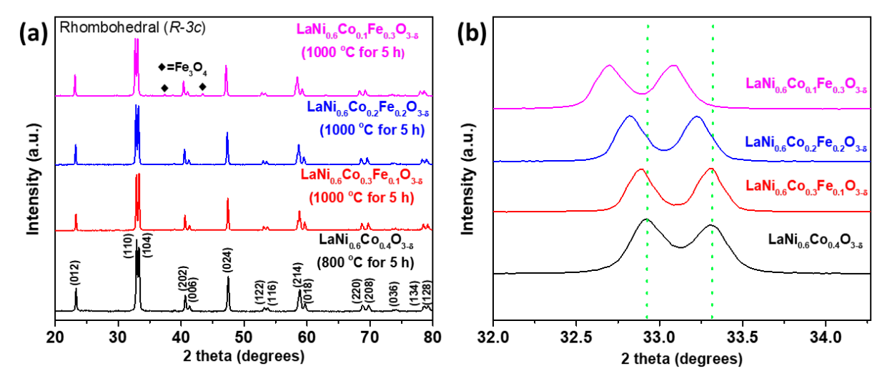
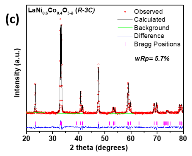
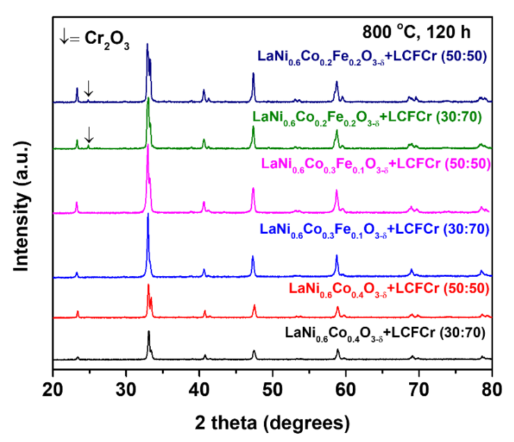
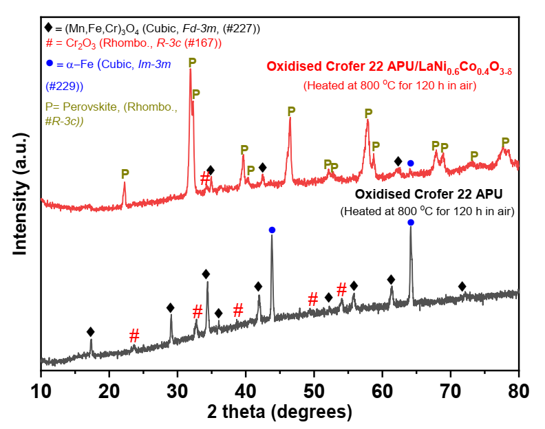
3. Results and Discussion
4. Conclusions
Author Contributions
Funding
Institutional Review Board Statement
Informed Consent Statement
Data Availability Statement
Acknowledgments
Conflicts of Interest
References
- Mogensen, M.B.; Chen, M.; Frandsen, H.L.; Graves, C.; Hansen, J.B.; Hansen, K.V.; Hauch, A.; Jacobsen, T.; Jensen, S.H.; Skafte, T.L.; et al. Reversible solid-oxide cells for clean and sustainable energy. Clean Energy 2019, 3, 175–201. [Google Scholar] [CrossRef]
- Kwon, Y.; Kang, S.; Bae, J. Development of a PrBaMn2O5+δ-La0.8Sr0.2Ga0.85Mg0.15O3−δ composite electrode by scaffold infiltration for reversible solid oxide fuel cell applications. Int. J. Hydrog. Energy 2020, 45, 1748–1758. [Google Scholar] [CrossRef]
- Mogensen, M.B. Materials for reversible solid oxide cells. Curr. Opin. Electrochem. 2020, 21, 265–273. [Google Scholar] [CrossRef]
- Shen, M.; Ai, F.; Ma, H.; Xu, H.; Zhang, Y. Progress and prospects of reversible solid oxide fuel cell materials. iScience 2021, 24, 103464. [Google Scholar] [CrossRef]
- Simner, S.P.; Anderson, M.D.; Pederson, L.R.; Stevenson, J.W. Performance variability of La(Sr)FeO3 SOFC cathode with Pt, Ag and Au current collectors. J. Electrochem. Soc. 2005, 152, A1851–A1859. [Google Scholar] [CrossRef]
- Mori, M.; Liu, Y. La0.6Sr0.4Co0.2Fe0.8O3−δ current collectors via Ag infiltration for microtubular solid oxide fuel cells with intermediate temperature operation. J. Electrochem. Soc. 2009, 156, B1182–B1187. [Google Scholar] [CrossRef]
- Tucker, M.C.; Cheng, L.; DeJonghe, L.C. Selection of cathode contact materials for solid oxide fuel cells. J. Power Sources 2011, 196, 8313–8322. [Google Scholar] [CrossRef]
- Morán-Ruiz, A.; Vidal, K.; Larrañaga, A.; Arriortua, M.I. Chemical compatibility and electrical contact of LaNi0.6Co0.4O3−δ (LNC) between Crofer22APU interconnect and La0.6Sr0.4FeO3 (LSF) cathode for IT-SOFC. Fuel Cells 2013, 13, 398–403. [Google Scholar] [CrossRef]
- Wilkinson, L.T.; Zhu, J.H. Ag-Perovskite composite materials for SOFC cathode–interconnect contact. J. Electrochem. Soc. 2009, 156, B905–B912. [Google Scholar] [CrossRef]
- Yang, Z.; Xia, G.; Singh, P.; Stevenson, J.W. Electrical contacts between cathodes and metallic interconnects in solid oxide fuel cells. J. Power Sources 2006, 155, 246–252. [Google Scholar] [CrossRef]
- Stodolny, M.K.; Boukamp, A.B.; Blank, D.H.A.; Van Berkel, F.P.F. La(Ni,Fe)O3 stability in the presence of chromia—A solid-state reactivity study. J. Electrochem. Soc. 2011, 158, B112–B116. [Google Scholar] [CrossRef] [Green Version]
- Sharma, V.I.; Yildiz, B. Degradation mechanism in La0.8Sr0.2CoO3 as contact layer on the solid oxide electrolysis cell anode. J. Electrochem. Soc. 2010, 157, B441–B448. [Google Scholar] [CrossRef]
- Kim, S.J.; Kim, K.J.; Choi, G.M. Effect of Ce0.43Zr0.43Gd0.1Y0.04O2−δ contact layer on the stability of the interface between GDC interlayer and YSZ electrolyte in the solid oxide electrolysis cell. J. Power Sources 2015, 284, 617–622. [Google Scholar] [CrossRef]
- Molero Sánchez, B. Development of Oxygen Electrodes for Reversible Solid Oxide Fuel Cells. Ph.D. Thesis, University of Calgary, Calgary, AB, Canada, 2017. [Google Scholar]
- Molero Sánchez, B.; Addo, P.; Buyukaksoy, A.; Birss, V. Performance enhancement of La0.3Ca0.7Fe0.7Cr0.3O3−δ air electrodes by infiltration methods. J. Electrochem. Soc. 2017, 164, F3123–F3130. [Google Scholar] [CrossRef]
- Quick Info. 2021. Available online: http://seeo2energy.com/ (accessed on 8 December 2021).
- Molero Sánchez, B.; Prado-Gonjal, J.; Ávila-Brande, D.; Chen, M.; Morán, E.; Birss, V. High performance La0.3Ca0.7Cr0.3Fe0.7O3−δ air electrode for reversible solid oxide fuel cell applications. Int. J. Hydrog. Energy 2015, 40, 1902–1910. [Google Scholar] [CrossRef]
- Molero Sánchez, B.; Prado-Gonjal, J.; Ávila-Brande, D.; Chen, M.; Morán, E.; Birss, V. Microwave-assisted synthesis and characterization of new cathodic material for solid oxide fuel cells: La0.3Ca0.7Fe0.7Cr0.3O3−δ. Ceram. Int. 2015, 41, 8411–8416. [Google Scholar] [CrossRef]
- Addo, P.K.; Molero Sánchez, B.; Chen, M.; Paulson, S.; Birss, V. CO/CO2 study of high performance La0.3Sr0.7Fe0.7Cr0.3O3−δ reversible SOFC electrodes. Fuel Cells 2015, 15, 689–696. [Google Scholar] [CrossRef]
- Molero Sánchez, B.; Addo, P.K.; Buyukaksoy, A.; Paulson, S.; Birss, V. Electrochemistry of La0.3Sr0.7Fe0.7Cr0.3O3−δ as an oxygen and fuel electrode for RSOFCs. Faraday Discuss. 2015, 182, 159–175. [Google Scholar] [CrossRef]
- Addo, P.K.; Molero Sánchez, B.; Buyukaksoy, A.; Paulson, S.; Birss, V. Sulfur tolerance of La0.3M0.7Fe0.7Cr0.3O3−δ (M = Sr, Ca) solid oxide fuel cell anodes. ECS Trans. 2015, 66, 219. [Google Scholar] [CrossRef]
- Masood Ansari, H.; Stuart, B.A.; Ahmad, N.; Birss, V. Unraveling the evolution of exsolved Fe–Ni alloy nanoparticles in Ni-doped La0.3Ca0.7Fe0.7Cr0.3O3−δ and their role in enhancing CO2–CO electrocatalysis. J. Mater. Chem. A 2021. [Google Scholar] [CrossRef]
- Zhu, J.H.; Ghezel-Ayagh, H. Cathode-side electrical contact and contact materials for solid oxide fuel cell stacking: A review. Int. J. Hydrog. Energy 2017, 42, 24278–24300. [Google Scholar] [CrossRef]
- Shong, W.-J.; Liu, C.-K.; Yang, P.; Lee, R.-Y.; Lin, K.-F. Evaluation of Ag–NiO mixture as a cathode contact material for solid oxide fuel cell applications. J. Ceram. Soc. Jpn. 2017, 125, 202–207. [Google Scholar] [CrossRef]
- Singh, P.; Yang, Z.; Viswanathan, V.; Stevenson, J.W. Observations on the structural degradation of silver during simultaneous exposure to oxidizing and reducing environments. J. Mater. Eng. Perform. 2004, 13, 287–294. [Google Scholar] [CrossRef]
- Lu, Z.G.; Zhu, J.H. Thermal Evaporation of pure Ag in SOFC-relevant environments. Electrochem. Solid State Lett. 2007, 10, B179–B182. [Google Scholar] [CrossRef]
- Morán-Ruiz, A.; Vidal, K.; Laguna-Bercero, M.Á.; Larrañaga, A.; Arriortua, M.I. Effects of using (La0.8Sr0.2)0.95Fe0.6Mn0.3Co0.1O3 (LSFMC), LaNi0.6Fe0.4O3−δ (LNF) and LaNi0.6Co0.4O3−δ (LNC) as contact materials on solid oxide fuel cells. J. Power Sources 2014, 248, 1067–1076. [Google Scholar] [CrossRef] [Green Version]
- Budiman, R.A.; Uzumaki, Y.; Hong, H.J.; Miyazaki, T.; Hashimoto, S.; Nakamura, T.; Yashiro, K.; Amezawa, K.; Kawada, T. Oxygen nonstoichiometry and transport properties of LaNi0.6Co0.4O3−δ. Solid State Ion. 2016, 292, 52–58. [Google Scholar] [CrossRef] [Green Version]
- Qiu, L.; Ichikawa, T.; Hirano, A.; Imanishi, N.; Takeda, Y. Ln1−xSrxCo1−yFeyO3−δ (Ln = Pr, Nd, Gd; x = 0.2, 0.3) for the electrodes of solid oxide fuel cells. Solid State Ion. 2003, 158, 55–65. [Google Scholar] [CrossRef]
- Zhao, L.; Shen, J.; He, B.; Chen, F.; Xia, C. Synthesis, characterization and evaluation of PrBaCo2−xFexO5+δ as cathodes for intermediate-temperature solid oxide fuel cells. Int. J. Hydrog. Energy 2011, 36, 3658–3665. [Google Scholar] [CrossRef]
- Choi, S.; Yoo, S.; Kim, J.; Park, S.; Jun, A.; Sengodan, S.; Kim, J.; Shin, J.; Jeong-Young, H.; Choi-Man, Y.; et al. Highly efficient and robust cathode materials for low-temperature solid oxide fuel cells: PrBa0.5Sr0.5Co2−xFexO5+δ. Sci. Rep. 2013, 3, 2426. [Google Scholar] [CrossRef] [Green Version]
- Ullmann, H.; Trofimenko, N.; Tietz, F.; Stover, D.; Ahmad-Khanlou, A. Correlation between thermal expansion and oxide ion transport in mixed conducting perovskite-type oxides for SOFC cathodes. Solid State Ion. 2000, 138, 79–90. [Google Scholar] [CrossRef]
- Huczkowski, P.; Christiansen, N.; Shemet, V.; Niewolak, L.; Abellan, J.; Singheiser, L.; Quadakkers, W.J. Growth mechanisms and electrical conductivity of oxide scales on ferritic steels proposed as interconnect materials for SOFC’s. Fuel Cells 2006, 6, 93–99. [Google Scholar] [CrossRef]
- Quadakkers, W.J.; Shemet, V.; Singheiser, L. High-Temperature Material. U.S. Patent No US6936217B2, 2003. [Google Scholar]
- VDM® Crofer 22 APU. 2021. Available online: https://www.vdm-metals.com/fileadmin/user_upload/Downloads/Data_Sheets/Data_Sheet_VDM_Crofer_22_APU.pdf (accessed on 8 December 2021).
- Shannon, R.D. Revised effective ionic radii and systematic studies of interatomic distances in halides and chalcogenides. Acta Cryst. 1976, 32, 751–767. [Google Scholar] [CrossRef]
- Nagai, T.; Ito, W.; Sakon, T. Change in the thermal expansion of a perovskite-type mixed conductor upon sample density. J. Am. Ceram. Soc. 2008, 91, 303–307. [Google Scholar] [CrossRef]
- Marrocchelli, D.; Bishop, R.S.; Tuller, H.L.; Yildiz, B. Understanding chemical expansion in non-stoichiometric oxides: Ceria and zirconia case studies. Adv. Funct. Mater. 2012, 22, 1958–1965. [Google Scholar] [CrossRef]
- Sun, J.; Liu, X.; Han, F.; Zhu, L.; Bi, H.; Wang, H.; Yu, S.; Pei, L. NdBa1−xCo2O5+δ as cathode materials for IT-SOFC. Solid State Ion. 2016, 288, 54–60. [Google Scholar] [CrossRef]
- Huang, K.; Lee, H.Y.; Goodenough, J.B. Sr- and Ni-Doped LaCoO3 and LaFeO3 Perovskites. J. Electrochem. Soc. 1998, 145, 3220–3227. [Google Scholar] [CrossRef]
- Takahashi, H.; Munakata, F.; Yamanaka, M. Ab initio study of the electronic structures in LaCoO3–SrCoO3 systems. Phys. Rev. B 1998, 57, 15211. [Google Scholar] [CrossRef]
- Lee, K.T.; Manthiram, A. LaSr3Fe3−yCoyO10−δ (0 ≤ y ≤ 1.5) intergrowth oxide cathodes for intermediate tem-perature solid oxide fuel cells. Chem. Mater. 2006, 18, 1621–1626. [Google Scholar] [CrossRef]
- Hjalmarsson, P.; Søgaard, M.; Hagen, A.; Mogensen, M. Structural properties and electrochemical performance of strontium- and nickel-substituted lanthanum cobaltite. Solid State Ion. 2008, 179, 636–646. [Google Scholar] [CrossRef]


| Composition | CT (°C)/ Time (h) | ST (°C)/Time (h) | Relative Density of Pellets (%) |
|---|---|---|---|
| LaNi0.6Co0.4O3−δ | 800/5 | 1300/5 | ~97 |
| LaNi0.6Co0.3Fe0.1O3−δ | 1000/5 | 1300/5 | ~95 |
| LaNi0.6Co0.2Fe0.2O3−δ | 1000/5 | 1300/5 | ~93 |
| LaNi0.6Co0.1Fe0.3O3−δ | 1000/5 | -- | ~93 |
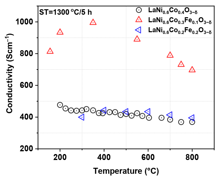
| Composition | Lattice Parameters | σ (800 °C) (S·cm−1) | |
|---|---|---|---|
| a, b (Å) | c (Å) | ||
| LaNi0.6Co0.4O3−δ | 5.4681 (3) | 13.1622 (9) | ~369 |
| LaNi0.6Co0.3Fe0.1O3−δ | 5.4729 (1) | 13.1614 (5) | ~697 |
| LaNi0.6Co0.2Fe0.2O3−δ | 5.4827 (3) | 13.1937 (6) | ~395 |
| LaNi0.6Co0.1Fe0.3O3−δ | 5.4935 (3) | 13.2282 (7) | -- |
Publisher’s Note: MDPI stays neutral with regard to jurisdictional claims in published maps and institutional affiliations. |
© 2022 by the authors. Licensee MDPI, Basel, Switzerland. This article is an open access article distributed under the terms and conditions of the Creative Commons Attribution (CC BY) license (https://creativecommons.org/licenses/by/4.0/).
Share and Cite
Singh, K.; Addo, P.K.; Thangadurai, V.; Prado-Gonjal, J.; Molero-Sánchez, B. LaNi0.6Co0.4−xFexO3−δ as Air-Side Contact Material for La0.3Ca0.7Fe0.7Cr0.3O3−δ Reversible Solid Oxide Fuel Cell Electrodes. Crystals 2022, 12, 73. https://0-doi-org.brum.beds.ac.uk/10.3390/cryst12010073
Singh K, Addo PK, Thangadurai V, Prado-Gonjal J, Molero-Sánchez B. LaNi0.6Co0.4−xFexO3−δ as Air-Side Contact Material for La0.3Ca0.7Fe0.7Cr0.3O3−δ Reversible Solid Oxide Fuel Cell Electrodes. Crystals. 2022; 12(1):73. https://0-doi-org.brum.beds.ac.uk/10.3390/cryst12010073
Chicago/Turabian StyleSingh, Kalpana, Paul Kwesi Addo, Venkataraman Thangadurai, Jesús Prado-Gonjal, and Beatriz Molero-Sánchez. 2022. "LaNi0.6Co0.4−xFexO3−δ as Air-Side Contact Material for La0.3Ca0.7Fe0.7Cr0.3O3−δ Reversible Solid Oxide Fuel Cell Electrodes" Crystals 12, no. 1: 73. https://0-doi-org.brum.beds.ac.uk/10.3390/cryst12010073