Article

A New Insight into the Role of Silicate-Type Binders on the Crushing Strength of Alumina Foams

by
Fernando de Almeida Costa Oliveira
1,*,
Stéphane Pommier
2,
Jorge Cruz Fernandes
3 and
Diamantino Dias
4
1
Laboratório Nacional de Energia e Geologia, I.P., Laboratory of Energy, Materials for Energy Unit, Estrada do Paço do Lumiar, 1649-038 Lisboa, Portugal
2
Institut Universitaire de Technologie du Limousin, Université de Limoges, 12 allée André-Maurois, CEDEX, 87065 Limoges, France
3
IDMEC—Mechanical Engineering Institute, Instituto Superior Técnico, University of Lisbon, Av. Rovisco Pais, 1049-001 Lisboa, Portugal
4
Rauschert Portuguesa, S.A., Estrada Nacional 249-4, Trajouce, 2785-653 São Domingos de Rana, Portugal
*
Author to whom correspondence should be addressed.
Submission received: 7 September 2022 / Revised: 26 September 2022 / Accepted: 29 September 2022 / Published: 2 October 2022

Abstract

:
Semi-closed cell macroporous alumina foams with relative densities ranging from 0.26 to 0.35 have been produced by the well-established replication method based on the coating of a polyurethane (PU) template foam by a ceramic slurry, followed by burnout of the PU template, and sintering of the ceramic skeleton. Collapse of the three-dimensional structure upon the volatilisation of the PU sponge can only be prevented using appropriate binders. Scarce data are available on the slurry formulations of commercial alumina foams. The aim of this study was to investigate the influence of silicate-type binders, namely kaolin and bentonite additives, on the crushing strength of alumina foams. The highest crushing strength of around 10 MPa was observed at a porosity of 66 ± 2%. The open-cell model is inadequate to fit the crushing strength data of such semi-closed cell type structures. Both microscopic and macroscopic flaws resulting from the foam processing method contribute to the wide scatter of the strength, thereby explaining the Weibull modulus ranging from 4 to 7. Both flaw populations require further improvement to maximise the crushing strength of these foams with high potential for the design of structured catalyst carriers and molten aluminium filters.

1. Introduction

Cellular ceramics materials are being increasingly used for many engineering purposes, particularly at high temperatures [1,2,3,4,5]. Cellular ceramics have several unique properties, such as high chemical and thermal stability, low mass and thermal conductivity, and high gas permeability and porosity, which make them lightweight structures.
Seeking the unique properties of these light materials has led to the development of the so-called engineered macroporous ceramics [6,7,8]. These materials have a high potential for many applications, such as catalyst substrates [9] and scaffolds for tissue engineering [10]. The term foam ought to be used only when the relative density of the material (density of the cellular solid divided by that of the solid it is made from) is < 0.3 [1].
The most widely used cellular materials are natural solids, such as wood and sponge, but synthetic cellular materials such as polymers and metals, and more recently ceramics, are being employed for the manufacturing of foams [11,12,13,14,15,16,17,18,19,20,21].
Among the materials currently being used to fabricate ceramic foams, oxide ceramics, such as alumina (Al2O3) [22,23] and zirconia (ZrO2) [24], are the most common ones, whereas non-oxide ceramics, such as silicon carbide (SiC) [25], are the most widely employed on the filtration market.
Unlike dense ceramics, the mechanical behaviour of highly porous ceramics is greatly influenced by their microstructure. The porous disordered nature of the cellular structure makes it difficult to model the relationship between macroscopic properties and structure. Indeed, the properties of a cellular material depend not only on the solid material making up the structure but also on the cell size, cell shape, type of porosity, and relative density. Additionally, the connectivity between cell walls can have a major contribution to the mechanical properties of such materials. For certain mechanical, thermal, and electrical properties of cellular materials, the percolation theory seems to be applicable. This theory uses power laws describing the effective properties as a function of the relative density. Accordingly, the relationship between ceramic foam properties and porosity is typically given by:
f o a m   p r o p e r t y s o l i d   p r o p e r t y = C i ( 1 ε ) n i
where: Ci and ni are constants dependent on the foam structure.
A comprehensive review of the mechanical behaviour of cellular ceramics highlights that most cellular ceramics are based on polymers and several attempts were made to develop micromechanical models, assuming that elastic deformations are primarily tensile and are carried by the cell edges [26].
Considering a simple cubic unit cell consisting of beams that form cell edges and plates which form the cell walls and where deformation is controlled by the bending of the struts within the unit cell, a sound approach for understanding the mechanical behaviour of cellular ceramics has been established [1]. The mechanical properties of cellular solids are thereby related to the mechanics of the expected deformation processes in the bulk cellular body, namely bending, buckling of cell edges and brittle fracture of its cell walls. In addition to using micromechanical models to describe the linear elastic behaviour of foams, the following relationship between crushing strength and relative density for brittle foams was derived:
σ c f σ f s = C 1 ( ρ ρ s ) 3 2
where σcf is the crushing strength of brittle foams; σfs the modulus of rupture of the cell wall material (typically of the order of 400 MPa for alumina [8]); C1~0.65 and (ρ/ρs) the relative density of the material [27]. This model assumes that a cell wall fails when the moment (Mf) acting on it exceeds:
M f = 1 6 σ f s t 3
where t is the square cross-section beam cell thickness and Mf is the fracture moment.
For higher-density (relative density > 0.1) materials, the solid present in the corners contributes to the density and must therefore be considered in the model [28]. During the fabrication of the foams, solid accumulates in the cell edges, because of surface tension, thickening the edges relative to the faces. The cell edges, therefore, carry most of the load when the open-cell foam is compressed, since the faces are so thin that their contribution to strength can be regarded as being very little, even though the bending of cell edges sets some of the thin faces in tension. Using the simple geometry consisting of a simple array of struts of square cross-section t and length L, the following equations were obtained:
ρ ρ s = ( t / l ) 2 + 0.766 ( t / l ) 3 0.766 ( 1 + t / l ) 3
σ c f σ f s = C 2 ( t / l ) 3 ( 1 + t / l ) 2
where the entire strut length is L = 1/2t + l +1/2t, l is the free unsupported length and C2 is a constant characteristic of the cellular geometry [28].
Based on the strut strength measurements of high purity alumina foams, with relative densities ranging from 0.09 to 0.25, the calculated exponent for Equation (2) was 1.70 with a 95% confidence interval of (1.46, 1.95), i.e., slightly higher than the theoretical value (1.5) [29]. For such measurements, a thin steel wire beneath the strut was used in direct contact with the load cell. A minimum of 30 strut measurements were carried out. The low Weibull modulus of the struts (2 to 3) indicates a wide flaw distribution. Both microscopic flaws, which consist of pores or cracks within the strut walls, and macroscopic flaws, include broken cell struts and triangular hollow struts in the structure, contribute to the scatter of strength in these materials and must be controlled to maximise the crushing strength of these open-cell ceramics.
The limited data still available in the literature were considered as being insufficient to give confidence that Equations (2) and (5) provide a good description of the crushing strength as a function of the relative density of brittle foams [30]. Experimental data obtained for cordierite foams revealed that the exponent was ≈3.3, i.e., twice that predicted by the model described by Equation (2) over the range of relative densities investigated (80% to 90%) [31]. Such discrepancy is attributed to several factors, including the morphological differences in the structural unit of the developed foams compared to a cubic open-cell foam, the presence of both open and closed cells, and the presence of non-periodic cells. Both the constant C1 and the density exponent are sensitive to the assumed values of σfs. The constant C1 for an isotropic foam was estimated to be equal to 0.16, assuming a tetrakaidekahedron unit cell [32].
Most data available in the literature regarding the compressive behaviour of ceramic foams concern typically (open cell) reticulated foams. Alumina foams are also being regarded as suitable catalyst supports in catalytical cracking processes. For such applications, the presence of closed cell windows allows for an increase in the geometric area of such foams. This would favour the increase in catalytically active sites. One should bear in mind that alumina foams have high temperature stability, but a low specific surface area, typically around 1 m2 g−1. This value needs to be significantly improved either through the application of an adequate washcoat or an additional increase in the porosity of the struts and cell walls of the foams. Such increase in porosity will result in a decrease in compressive strength. Thence, this work aimed to fabricate semi-closed cell alumina foams by the replication method using both kaolinite and bentonite binders, and to compare their crushing strengths. Indeed, it is well established that various clays, such as bentonite, ball clay, and kaolin, are regarded as beneficial against the collapse of the ceramic structure during the burnout of the polymeric template sponge and to optimise the rheological properties of the slurries [13]. However, there is no systematic investigation on the effect of such additives on the resistance to compression of alumina foams. To this end, it is important to characterise the raw materials since their characteristics greatly influence the mechanical properties of the developed foams.
The major outcome of this work was the development of a method of manufacturing alumina foams, reliably, with a minimum binder content.

2. Materials and Methods

2.1. Raw Materials

Commercial alumina powder from Almatis GmbH (F. R. Ludwigshafen am Rhein, Germany); designated by CT3000SG (batch 0521013320), was used. It was characterised using several techniques. Specific surface area was determined by means of a Monosorb MS-10 analyser, made by Quanta Chrome Corp., Boynton Beach, FL, USA. The apparent density was measured using a Hall flowmeter whereas flow time was determined on a Carney’s flowmeter. The tap density measurements were carried out in accordance with the EN 725-8:2006 standard. Finally, the true density was obtained by Helium pycnometry, using a AccuPyc 1330 Pycnometer made by Micrometrics Inc. Corp., Norcross, GA, USA.
Kaolin and bentonite clays, both supplied by Rauschert Portuguesa Lda. (São Domingos de Rana, Portugal), hereafter denoted as binders A (kaolin) and B (bentonite), were required to prevent the collapse of the foam structure during polymer removal and to optimise the rheological properties of the slurries, Table 1.
Kaolin clay contains kaolinite (82%) and quartz (8%) as main crystalline phases, together with muscovite (8%) and potassium feldspar (2%). Kaolinite has a two-layer structure of [(Si2O5)]2− and [Al2(OH)4]2+ molecular sheets with a nominal theoretical composition of Al2O3·2SiO2·2H2O or Al2Si2O5(OH)4 consisting of 39.5 wt.% Al2O3, 46.5 wt.% SiO2 and 14 wt.% H2O.
Bentonite is a clay composed mostly of montmorillonite (83%), quartz (7%), mica (4%), feldspar (2%), calcite (2%) and dolomite (2%).
The polymeric foams were manufactured by FLEXIPOL—Espumas Sintéticas, S.A. (São João da Madeira, Portugal). Polyurethane sponge, referred to as 20BR, was supplied in a cuboid shape with a density of 22 kg m−3. The mean cell size of the foam template was 687 ± 186 µm (ca. 40 ppi).

2.2. Ceramic Foam Manufacturing

Alumina foams were fabricated by the replication method [13]. Aqueous slurries with a solid content of 60 wt.% to 65 wt.% were prepared by mixing the ceramic particles in distilled water with various additive contents, Table 2.
Dispersion and homogenisation of the resulting slurries were achieved by ball milling using alumina balls for 12 h. Particle size distribution of the slurries was measured using a CILAS 1064 (Orleans, France) particle size analyser. The rheology of the slurries was optimised for each material. A commercial dispersant (Targon 1128, BK, Ladenburg, Germany) was used to adjust the viscosity of the slurries and obtain thixotropic behaviour (~1 wt.% of the total solid content). This means that the slurry behaves like a liquid when stirred and behaves as a solid as soon as the movement is stopped [33]. Otherwise, material gradients across the foams may result.
Special attention was paid to the immersion step, to guarantee that most of the entrapped air in the polymeric foam structure was thoroughly removed. Foam samples were dipped into the slurry and compressed to fill the void space. Then, the excess slurry was removed from the foam by passing it through a set of rotating rollers. The distance between the rollers was set at 5 mm, and the ratio between the height of the PU foams and the rollers’ distance was 3.3.
The foams were then dried under well-controlled humidity and heat conditions for 12 h. The temperature varied from 25 to 95 °C and the initial relative humidity was set at 60%.
Thereof, the burnout cycle of the polymeric templates was optimised to avoid the collapse of the foam structures using a Dankiln oven (Denmark), at temperatures up to 500 °C for 1 h, and a heating rate of 1 °C min−1 in static air. Once the content of additives needed to prevent the collapse of the structures was optimised, both burnout and sintering thermal cycles were carried out in an industrial electrical furnace at Rauschert Portuguesa Lda. The alumina foams were sintered at 1650 °C for 2 h.

2.3. Ceramic Foams Characterisation

Specimens were accurately measured after sintering to determine their volume. The bulk density and porosity of the resulting foams were determined from the mass-to-volume ratio. The true density of the solid material making up the ceramic foams was also determined using the He pycnometer, after crushing the foams into a fine powder using a mortar and pestle. The foams’ porosity was calculated according to:
ε = ( 1 ρ ρ s ) 100
where: ε is the foam porosity (in per cent); ρ is the bulk density of the foam; ρs is the true density of the solid making up the foam.
Crushing strength, or compressive strength, is the maximum stress a material can sustain under compression loading. The compressive strength of a material that fails by shattering fracture can be defined within fairly narrow limits as an independent property.
The crushing strength (σcs) was measured on cuboid blocks (about 22 mm × 22 mm × 13 mm) using a standard mechanical testing apparatus (Model 4302, Instron Corporation, Canton, MA, USA), fitted with a 10 kN load cell and flat steel plates, closing with a crosshead rate of 0.5 mm min−1. The cross-sectional area of the sample and the maximum failure load observed during testing were used to calculate the fracture stress. When testing cellular materials, it is important to ensure uniform loading over the entire foam. Otherwise, one can considerably underestimate the true crushing strength if non-compliant loading rams are used. As the surfaces of the foam test samples were not entirely flat, a compliant polyvinyl chloride flexible layer (2 mm thick) was used between the loading rams and the samples to assist in uniformly loading the bulk alumina foams, Figure 1. This ensures that the experimental scatter is reduced and increases the likelihood of sudden crack propagation rather than damage accumulation.

3. Results and Discussion

3.1. Raw Materials Characterisation

The alumina powder was thoroughly characterised: the flow time is equivalent to a flow rate of 0.11 g s−1, whereas the Hausner ratio (tap to apparent density ratio) is 1.22, i.e., slightly lower than expected for a moderately cohesive powder (HR between 1.25 and 1.40), Table 3.

3.2. Ceramic Foam Manufacturing

The particle size distribution of the slurries prepared by ball milling was as follows: d10 = 0.16 ± 0.06 µm, d50 = 0.60 ± 0.18 µm and d90 = 2.57 ± 0.94 µm. After firing in the industrial furnace, some samples showed cracks because they became stuck to the support plates. Hence, upon cooling, large thermal stresses were imposed on the materials, leading to macro cracks propagation throughout the ceramic foams, Figure 2a. This is particularly evident for alumina foams made from slurries 2A and 2B, suggesting that a glassy phase formed upon sintering at temperatures as high as 1650 °C, causing localised bonding between the samples and the supporting plates. The amount of glassy phase present is below the detection limit of XRD analysis.
Kaolin and bentonite clays are important to minimise the danger of the alumina foam’s structure collapsing during and after removal of the organic material: up to 10 wt.% addition of clays to the slurries was recommended to avoid such collapse [13]. On the other hand, these clays happen to be a fluxing agent, which reduces firing temperatures. Therefore, it must be kept to a minimum (<3 wt.% in the present study) to avoid its detrimental effect on the rheology of the slurries and the formation of an undesirable glassy phase which decreases the strength of the alumina foams.
Upon heating, kaolinite undergoes a series of reactions yielding mullite (3Al2O3·2SiO2 with 72 wt.% Al2O3 and 28 wt.% SiO2) at high temperatures. Dehydroxylation of kaolinite occurs at temperatures around 260 °C and 580 °C, whereas transient alumina-type spinel starts to form at typically ca. 980 °C and mullite crystallisation takes place in a glassy phase above 1600 °C.
Bentonite is known for its high swelling capacity, as well as the ability to absorb a significant amount of polymer on its surface, thereby altering the rheological behaviour of slurries and playing a crucial role in the adsorption mechanism of non-ionic compounds on hydrophilic surfaces [34].
Both the ceramic foams made from the 59 wt.% alumina powder slurry containing either 1 wt.% of binders A or B collapsed during burnout of the polymeric templates, Figure 2b. This highlights that the content of silicate-like binders required to prevent the collapse of the alumina foams ought to be higher than 1 wt.%.

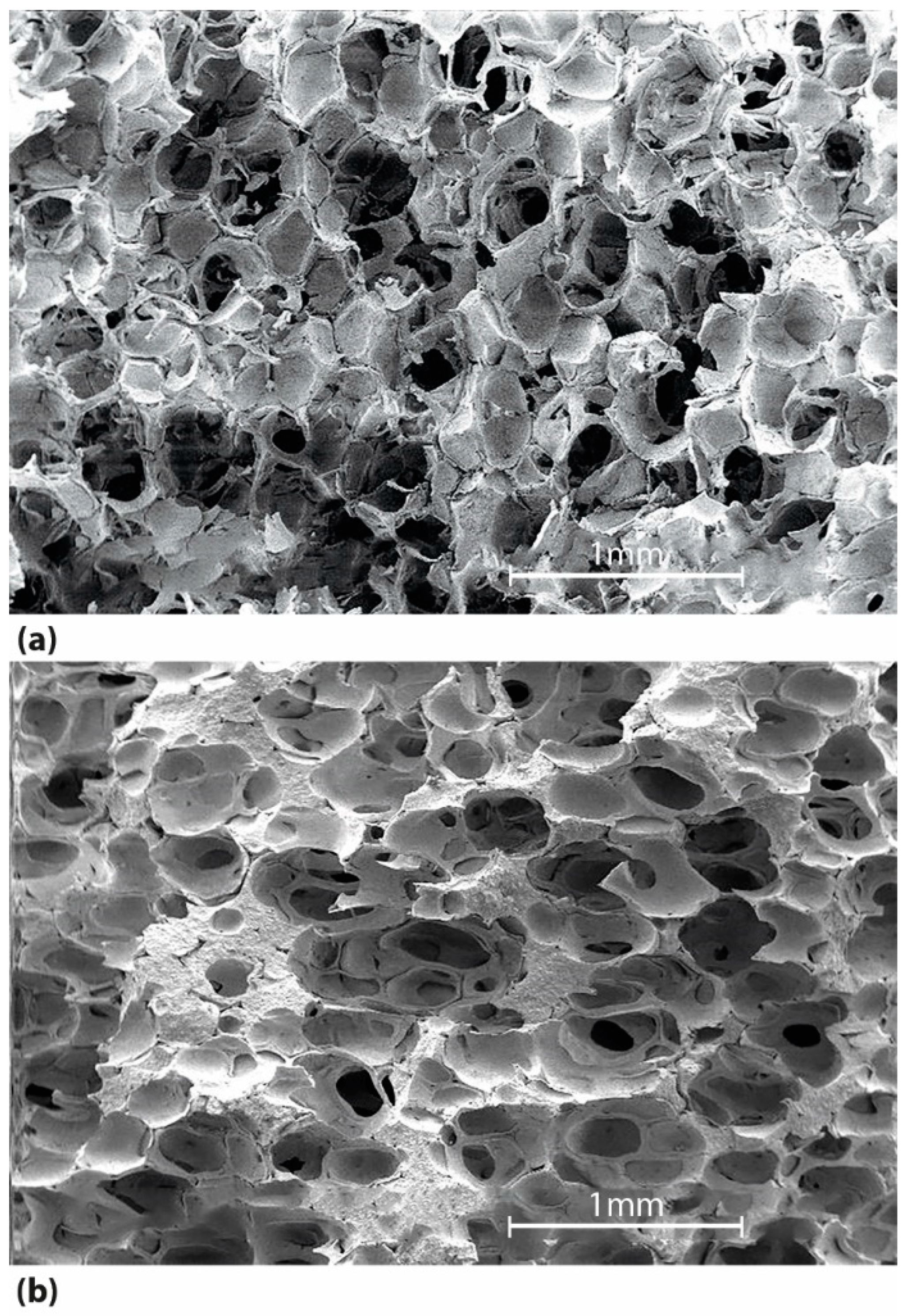
3.3. Ceramic Foams Characterisation

After sintering, the bulk density, relative density, and the porosity of each foam were measured (a minimum of 20 samples were produced for each slurry), Table 4.
The porosity of the alumina foams ranged from 64% to 75%, depending upon the slurry composition. The relative density is slightly higher than 0.3, except for Slurry 2A. This precludes the use of Equation (2) to estimate the crushing strength based on the relative density values of the fabricated foams. The exponent on the relative density term in Equation (2) is determined by the slope of the least-squares fit to the data.

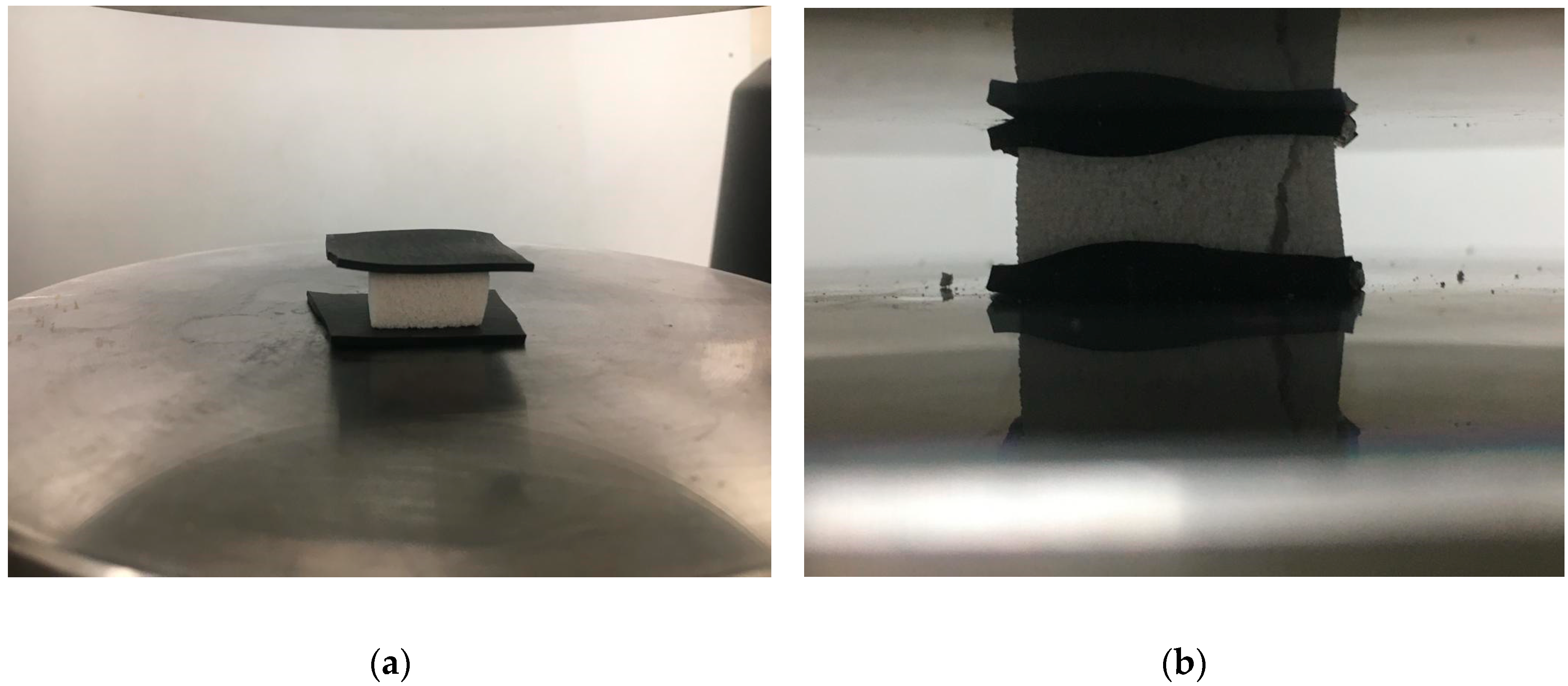
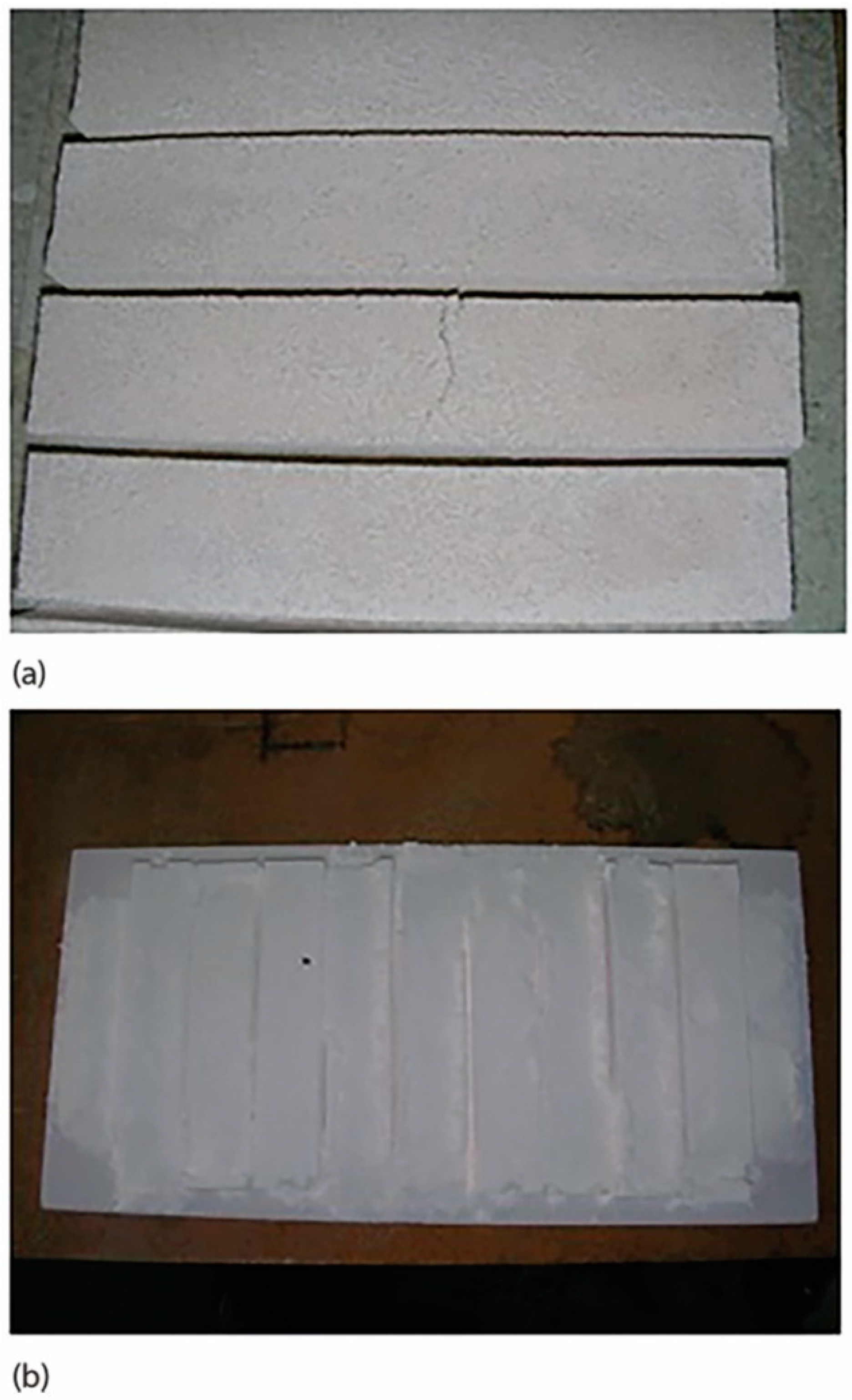
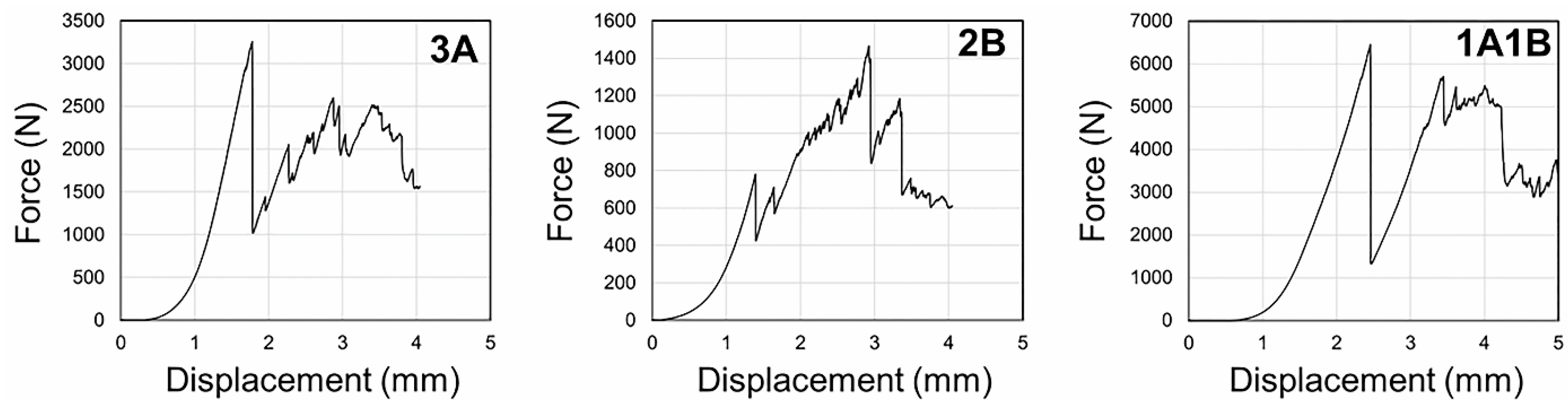
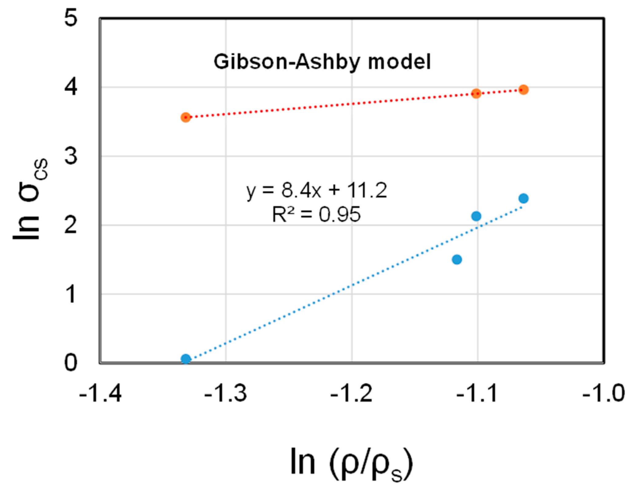
3.4. Crushing Strength

The crushing strengths of the fabricated foams (where n refers to the number of samples tested for each slurry) were measured for a minimum of 14 samples out of 20, indicating that the remaining ones contained manufacturing defects, and had to be discharged, Table 5.
Samples with lower porosity exhibited a typical brittle behaviour, i.e., after reaching the yield strength, catastrophic failure occurred owing to macroscopic crack propagation through the samples’ cross-section, as indicated by the sudden stress-drop in the force-displacement curves (3A and 1A1B). In contrast, samples with higher porosity (ε ~ 74%) presented a cellular-like behaviour where cracks do not propagate through the material, but fracture locally after buckling (2B), Figure 3.
Comparison with data reported in the literature is difficult because strength depends on the structures, which in turn varies with cell size, morphology, directionality (pores aligned in the direction of the applied load) and microstructure of both struts and cell walls. Up to now, there is no testing standard for the determination of the crushing strength of ceramic foams. Several experimental parameters, such as the rate of the applied load, the size and geometry of the loading plates, the use of a compliant pad between the loading plates and the sample, as well as the size of the sample, were found to affect the crushing strength as highlighted by Voigt et al. [35]. In particular, the sample size has a considerable effect on crushing strength, making comparisons difficult.
Considering that the failure occurs at a critical flaw size, the data can, however, be analysed using the weakest link theory. The probability Weibull function was found to be the most adequate way to describe the strength distribution of brittle ceramics [36]. The set of crushing strength was analysed using the two-parameter distribution model, where m is the shape parameter and σ0 is the scale parameter. The shape parameter m is known as the Weibull modulus and provides a measure of the scatter of the strength results, the lower the m value, the larger the extent of the scatter. The scale parameter is related to the distribution range so that the characteristic strength σ0 corresponds to a failure probability of 63.2%. The validity of the Weibull approach requires a relatively large number of test samples, say 20 or more. In the present study, a minimum of 14 samples out of 20 were tested, owing to defects occurring during manufacturing. The values presented in Table 5 were determined by the maximum likelihood technique, according to the ASTM C1239-13 [37]. The suitability of the Weibull distribution applied to porous ceramics was questioned [38,39]. Comparing four probability distributions, namely the Normal, Log-Normal, Weibull and Gamma to evaluate the crushing strength data of open-cell alumina foams has revealed that all distributions provide a sound representation of the data, since the differences between the goodness of fit (R2) were typically below 0.025 (except for the 30 ppi CS data series) [40].
The crushing strength of the alumina foams is primarily dependent on the (total) porosity of the foams. However, other parameters such as the type of additive used can also influence compressive strength. Higher crushing strengths were obtained for alumina foams produced using additive B. Increasing the solid load in the slurry from 60 wt.% to 65 wt.% also resulted in alumina foams having higher crushing strength. This is related to the raise in crushing strength with the increasing bulk density of the foams, as shown in Table 4. For a given composition, the bulk density will be dependent on the sintering conditions, namely the temperature and dwell time. The effect of the sintering temperature on the crushing strength of alumina foams containing 5 wt.% additives (TiO2, CaO and others) was investigated [41]. Strength increased from 0.27 MPa to 0.63 MPa when the temperature was raised from 1400 °C to 1500 °C, reaching a maximum of 1.3 MPa at 1550 °C. Overfiring did occur at 1600 °C, resulting in a slight decrease in strength (~1.2 MPa) attributed to grain growth. However, both the scatter of data and the dwell time were not provided.
The effect of porosity (in the range of 45% to 80%) on the compressive strength of ice-templated 3 mol% yttria-stabilised zirconia was evaluated to elucidate the validity of the Gibson and Ashby model (Equation (2)) for the prediction of the crushing strength [42]. This model describes the relationship between porosity and mechanical properties of cellular solids with open and closed-cell structures. It does not consider the effect of cell size on mechanical strength. An increase in crushing strength of open-cell alumina foams with increasing cell size was observed, owing to strut cracking at the smallest cell sizes [43]. On the other hand, the crushing strength of reticulated vitreous carbon (RVC) foams decreased with increasing cell size [44,45]. This difference in behaviour is attributed to the different microstructures. When ceramic foams are made by coating an open-cell polymer foam, the resulting struts are hollow, having a triangular hole shape (as seen in Figure 5 in ref. [31]), and numerous longitudinal strut cracks and cracks within the cell walls are present, owing to stresses arising from the drying and the burnout of the polymer. The origin of the strut cracking in alumina foams is attributed to the thermal expansion difference between the polymer and the ceramic coating, as α is 6 × 10⁻⁶ K−1 for alumina and around 100 × 10−6 K−1 for polyurethane [46]. In contrast, the struts in RVC foams are dense and triangular in cross-section, keeping the shape of the polymer foams. For this RVC foam, a value of the geometric constant C1 of 0.75 was calculated.
The tensile strength for a commercial Al2O3/50 vol.% ZrO2 (3.0 mol% Y2O3) open-celled material (with relative density in the range of 7% to 12%) was determined [47]. The scatter of the strength as a function of toughness data suggested that the size of the fracture-initiating crack appeared to be relatively independent of the material’s cell size.
The influence of the porosity on the uniaxial compression strength of porous alumina with porosities ranging from 30 vol.% to 75 vol.% was reported [48]. To produce such materials, a sacrificial template method and a gel casting process were combined. Polyethylene (PE) was used as a pore former. A transition in fracture mode from brittle to cellular-like fracture (by progressive damage accumulation) occurred at a porosity above 60 vol.% [48]. It was also noticed that the scatter of compressive strength decreased as the porosity increased.
The crushing strength of the developed foams was plotted as a function of the relative density, Figure 4. The exponent determined is 8.4, which is ca. 6 times higher than the slope of 1.5 predicted by the theoretical model (Equation (2)). It is important to realise that this type of plot does not consider the microstructure of the developed material and the assumptions of the model, which is based on a simple beam theory. Thus, the experimental values measured for the developed foams cannot be estimated based on the said model (Equation (2)). Not only the geometry of the cells resembles a simple cubic structure, but also the mechanism of fracture changed from cellular-like fracture, typical of open-cell foams, to brittle failure. The presence of closed thin cell walls may also affect the fracture process, thereby affecting the crack tip trajectory in such a way as to avoid closed cells.
The lowest density alumina foams made from Slurry 2A exhibited the lowest crushing resistance. Under compressive loading conditions, failure associated with the propagation of pre-existing cracks present within the struts supports the hypothesis that damage accumulation occurred before failure. This is further confirmed by the evidence suggesting that strut fracturing occurred, leading to spalling of debris at the contact area between the sample and the compliant layer, resulting from the cumulative damage of the structure. The sudden reduction events observed in the stress–strain curves are attributed to this spallation phenomenon.
As strut strength determines the mechanical behaviour of cellular solids, the crushing test can be used to evaluate processing parameters aimed at improving strut resistance. When working with materials whose properties are sensitive to the microstructure, one cannot use the available models to predict their mechanical behaviour. To make accurate predictions one must tailor the microstructure to achieve the desired properties.
The results of crushing strength are corroborated by evidence gathered by SEM observations, Figure 5. Fracture surfaces observed by SEM revealed that the structure of the alumina foams produced from slurries containing 58 wt.% alumina and 2 wt.% additive A (slurry 2A) are more porous than those observed for alumina foams made from slurries containing 58 wt.% alumina and 2 wt.% additive B (slurry 2B), Figure 5.
Indeed, the foams made from slurry 2A have a density of ca. 1.0 g cm−3 compared to 1.3 g cm−3 obtained for slurry 2B. Although most cells show closed-cell walls they are all interconnected making an exact replica of the original polyurethane templates. It is seen that the struts present in foams made from slurry 2B appear thicker than those observed in foams made from slurry 2A, judging from the localised areas where granular fracture morphology is apparent, Figure 5b. This would also account for the raise in crushing strength from 1 MPa to 8 MPa.
The effect of the inorganic binders on the phase composition of the alumina foams could not be investigated by XRD. The maximum amount added is close to the detection limit of this technique. It is most likely that the binders did form a (glassy) intergranular secondary phase contributing to the densification of the alumina powders. This aspect requires further investigation, which is out of the scope of the present study.

4. Conclusions

In this work, the type and content of binders added to the alumina slurries to prevent their collapse upon burnout of the polymeric templates were found to have a critical role in both the microstructure and the relative density of the resulting foams. When 1 wt.% binder was added to the slurries, the collapse of the alumina foams could not be avoided. SEM observations showed that the three-dimensional cell geometry of the foams developed are of the semi-closed type, meaning that many cells possess thin closed-cell windows. Both macro and microscopic flaws were observed throughout the structure, together with hollow struts.
The crushing strength of the foams raised with increasing relative density, in agreement with the theoretical model (Equation (2)). The results are, however, lower than those predicted by the model, since many pre-existing cracks account for the mechanical behaviour of the developed foams, which in turn is related to the thin coating of slurry applied to achieve a low density.
The crushing strength of the alumina foams was found to be dependent on the type of additive used. Higher crushing strengths were obtained for alumina foams produced using additive B. Increasing the solid load in the slurry also resulted in alumina foams having higher crushing strength when additive A was used, suggesting that fabrication of the alumina foams is very sensitive to the type of additive required to avoid the collapse of the structures upon removal of the polymeric template.
Fractography observations revealed that the most common fracture origins are lateral cracks within the struts. The fracture mode is sensitive to the relative density. Lower relative density (<0.33) favours a damage accumulation failure process, whilst increasing the relative density (≥0.33) results in catastrophic failure, typical of brittle ceramics, due to a macroscopic crack propagating through the sample, as indicated by a sudden stress drop in the stress–strain curve. One should tailor the strut properties, through processing control, to optimise the mechanical behaviour of the bulk alumina foams.

Author Contributions

Conceptualisation, F.d.A.C.O.; methodology, F.d.A.C.O., J.C.F.; validation, F.d.A.C.O., S.P., J.C.F. and D.D.; investigation, F.d.A.C.O., S.P., J.C.F. and D.D.; resources, F.d.A.C.O., D.D.; writing—original draft preparation, F.d.A.C.O.; writing—review and editing, F.d.A.C.O., J.C.F.; supervision, J.C.F.; project administration, F.d.A.C.O.; funding acquisition, J.C.F. All authors have read and agreed to the published version of the manuscript.

Funding

This research was funded by Fundação para a Ciência e a Tecnologia (FCT), through IDMEC, under LAETA, grant UIDB/50022/2020. The funding provided by FCT to INIESC-National Research Infrastructure for Concentrated Solar Energy through contract ALT20-03-0145-FEDER-022113 is also thanked.

Data Availability Statement

The datasets generated during and/or analysed during the current study are available from the corresponding author on reasonable request.

Acknowledgments

Thanks are due to Flexipol-Espumas Sintéticas SA, for donating the polyurethane foams.

Conflicts of Interest

The authors declare no conflict of interest.

References

  1. Gibson, L.J.; Ashby, M.F. Cellular Solids, Structure and Properties, 2nd ed; Cambridge University Press: Cambridge, UK, 1997. [Google Scholar]
  2. Colombo, P. Ceramics foams: Fabrication, properties and applications. In Key Engineering Materials; Kermel, C., Lardot, V., Libert, D., Urbain, I., Eds.; Trans Tech Publications: Zurich, Switzerland, 2002; Volume 206–213, pp. 1913–1918. [Google Scholar]
  3. Binner, J. Ceramic foams. In Cellular Ceramics: Structure, Manufacturing, Properties and Applications, 1st ed.; Scheffler, M.P., Colombo, P., Eds.; Wiley-VCH: Weinheim, Germany, 2005; Chapter 2.1; pp. 33–56. [Google Scholar]
  4. Colombo, P. Conventional and Novel Processing Methods for Cellular Ceramics. Philos. Trans. Roy. Soc. A 2006, 364, 109–124. [Google Scholar] [CrossRef]
  5. Costa Oliveira, F.A. Ceramic foams. In Foam Films and Foams–Fundamentals and Applications; Exerowa, D., Gochev, G., Platikanov, P., Liggieri, L., Miller, R., Eds.; CRC Press: Boca Raton, FL, USA; Taylor and Francis Group: Oxfordshire, UK, 2019; pp. 465–476. [Google Scholar]
  6. Chen, Y.; Wang, N.; Ola, O.; Xia, Y.; Zhu, Y. Porous ceramics: Light in weight but heavy in energy and environment technologies. Mater. Sci. Eng. Rep. R 2021, 143, 100589. [Google Scholar] [CrossRef]
  7. Ohji, T.; Fukushima, M. Macro-porous ceramics: Processing and properties. Int. Mater. Rev. 2012, 57, 115–131. [Google Scholar] [CrossRef]
  8. Studart, A.R.; Gonzenbach, U.T.; Tervoort, E.; Gauckler, L.J. Processing routes to macroporous ceramics: A review. J. Am. Ceram. Soc. 2006, 89, 1771–1789. [Google Scholar] [CrossRef]
  9. Ribeiro, F.; Silva, J.M.; Silva, E.; Vaz, M.F.; Costa Oliveira, F.A. Catalytic combustion of toluene on Pt zeolite coated cordierite foams. Catal. Today 2011, 176, 93–96. [Google Scholar] [CrossRef]
  10. Ranito, C.M.S.; Costa Oliveira, F.A.; Borges, J.P. Hydroxyapatite foams for bone replacement. In Key Engineering Materials; Li, P., Zhang, K., Colwell, C.W., Jr., Eds.; Trans Tech Publications Ltd.: Zurich, Switzerland, 2005; Volume 284–286, pp. 341–344. [Google Scholar]
  11. Montanaro, L.; Jorand, Y.; Fantozzi, G.; Negro, A. Ceramic foams by powder processing. J. Eur. Ceram. Soc. 1998, 18, 1339–1350. [Google Scholar] [CrossRef]
  12. Incera Garrido, G.; Patcas, F.C.; Lang, S.; Kraushaar-Czarnetzki, B. Mass transfer and pressure drop in ceramic foams: A description for different pore sizes and porosities. Chem. Eng. Sci. 2008, 63, 5202–5217. [Google Scholar] [CrossRef]
  13. Schwartzwalder, K.; Somers, A.V. Method of Making Porous Ceramic Articles. U.S. Patent 3,090,094, 21 May 1963. [Google Scholar]
  14. Lyckfeldt, O.; Ferreira, J.M.F. Processing of porous ceramics by ‘starch consolidation’. J. Eur. Ceram. Soc. 1998, 18, 131–140. [Google Scholar] [CrossRef]
  15. Fitzgerald, T.J.; Michaud, V.J.; Mortensen, A. Processing of microcellular SiC foams-Part II Ceramic foam production foams. J. Mater. Sci. 1995, 30, 1037–1045. [Google Scholar] [CrossRef]
  16. Qian, J.M.; Wang, J.P.; Qiao, G.J.; Jin, Z.H. Preparation of porous SiC ceramic with a woodlike microstructure by sol-gel and carbothermal reduction processing. J. Eur. Ceram. Soc. 2004, 24, 3251–3259. [Google Scholar] [CrossRef]
  17. Sepulveda, P.; Binner, J.G.P. Processing of cellular ceramics by foaming and in-situ polymerization of organic monomers. J. Eur. Ceram. Soc. 1999, 19, 2059–2066. [Google Scholar] [CrossRef] [Green Version]
  18. Sundermann, E.; Viedt, J. Method of Manufacturing Ceramic Foam Bodies. U.S. Patent 3,745,201, 10 July 1973. [Google Scholar]
  19. Ortega, F.S.; Sepulveda, P.; Pandolfelli, V.C. Monomer systems for the gel casting of foams. J. Eur. Ceram. Soc. 2002, 22, 1395–1401. [Google Scholar] [CrossRef]
  20. Green, D.J. Fabrication and mechanical properties of lightweight ceramics produced by sintering of hollow spheres. J. Am. Ceram. Soc. 1995, 68, 403–409. [Google Scholar] [CrossRef]
  21. Luyten, J.; Mullens, S.; Cooyman, J.; de Wild, A.M.; Thijs, I. New processing techniques of ceramic foams. Adv. Engineer. Mater. 2003, 5, 715–718. [Google Scholar] [CrossRef]
  22. Dammler, K.; Schelm, K.; Betke, U.; Fey, T.; Scheffler, M. Open-cellular alumina foams with hierarchical strut porosity by ice templating: A thickening agent study. Materials 2021, 14, 1060. [Google Scholar] [CrossRef] [PubMed]
  23. Lee, S.; Lee, C.Y.; Ha, J.H.; Lee, J.; Song, I.H.; Kwon, S.H. Enhancing compressive strength of reticulated porous alumina by optimizing processing conditions. Appl. Sci. 2021, 11, 4517. [Google Scholar] [CrossRef]
  24. Resende-Gonçalves, C.I.; Sampaio, N.; Moreira, J.; Carvalho, O.; Caramês, J.; Manzanares-Céspedes, M.C.; Silva, F.; Henriques, B.; Souza, J. Porous zirconia blocks for bone repair: An integrative review on biological and mechanical outcomes. Ceramics 2022, 5, 161–172. [Google Scholar] [CrossRef]
  25. Eom, J.H.; Kim, Y.W.; Raju, S. Processing and properties of macroporous silicon carbide ceramics: A review. J. Asian Ceram. Soc. 2013, 1, 220–242. [Google Scholar] [CrossRef] [Green Version]
  26. Brezny, R.; Green, D.J. Mechanical behavior of cellular ceramics. In Materials Science and Technology, Structure and Properties of Ceramics; Swain, M., Ed.; Wiley-VCH Verlag GmbH & Co. KGaA: Weinheim, Germany, 1994; Volume 11, pp. 463–516. [Google Scholar]
  27. Ashby, M.F. The mechanical properties of cellular solids. Metall. Trans A 1983, 14, 1755–1769. [Google Scholar] [CrossRef]
  28. Gibson, L.J.; Ashby, M.F. The mechanics of three-dimensional cellular materials. Proc. R. Soc. Lond. A 1982, 382, 43–59. [Google Scholar]
  29. Brezny, R.; Green, D.J. Fracture behavior of open-cell ceramics. J. Am. Ceram. Soc. 1989, 72, 1145–1152. [Google Scholar] [CrossRef]
  30. Maiti, S.K.; Gibson, L.J.; Ashby, M.F. Deformation and energy absorption diagrams for cellular solids. Acta Metall. 1984, 32, 1963–1975. [Google Scholar] [CrossRef]
  31. Costa Oliveira, F.A.; Dias, S.; Vaz, M.F.; Cruz Fernandes, J. Behaviour of open-cell cordierite foams under compression. J. Eur. Ceram. Soc. 2006, 26, 179–186. [Google Scholar] [CrossRef]
  32. Zhang, J.; Ashby, M.F. Theoretical Studies on Isotropic Foams; Report # CUED/C-Mats/TR 158; Cambridge University: Cambridge, UK, 1989. [Google Scholar]
  33. Voigt, C.; Aneziris, C.G.; Hubálková, J. Rheological characterization of slurries for the preparation of alumina foams via replica technique. J. Am. Ceram. Soc. 2015, 98, 1460–1463. [Google Scholar] [CrossRef]
  34. Luckham, P.F.; Rossi, S. The colloidal and rheological properties of bentonite suspensions. Adv. Colloid. Interface Sci. 1999, 82, 43–92. [Google Scholar] [CrossRef] [Green Version]
  35. Voigt, C.; Storm, J.; Abendroth, M.; Aneziris, C.; Kuna, M.; Hubálková, J. The influence of the measurement parameters on the crushing strength of reticulated ceramic foams. J. Mater. Res. 2013, 28, 2288–2299. [Google Scholar] [CrossRef]
  36. Weibull, W. A statistical distribution function of wide applicability. ASME J. Appl. Mech. 1951, 18, 293–297. [Google Scholar] [CrossRef]
  37. ASTM C1239-13; Standard Practice for Reporting Uniaxial Strength Data and Estimating Weibull Distribution Parameters for Advanced Ceramics. ASTM International: West Conshohocken, PA, USA, 2018.
  38. Keleş, Ö.; García, R.E.; Bowman, K.J. Deviations from Weibull statistics in brittle porous materials. Acta Mater. 2013, 61, 7207–7215. [Google Scholar] [CrossRef]
  39. Fedorov, A.V.; Gulyaeva, Y.K. Strength statistics for porous alumina. Powd. Technol. 2019, 343, 783–791. [Google Scholar] [CrossRef]
  40. Neumann, M.; Hubálková, J.; Voigt, C.; Grabenhorst, J.; Aneziris, C.G. On the fracture statistics of open-porous alumina foam structures. J. Eur. Ceram Soc. 2022, 42, 2331–2340. [Google Scholar] [CrossRef]
  41. Han, Y.; Li, J.; Wei, Q.; Tang, K. The effect of sintering temperatures on alumina foam strength. Ceram. Int. 2002, 28, 755–759. [Google Scholar] [CrossRef]
  42. Seuba, J.; Deville, S.; Guizard, C.; Stevenson, A.J. Mechanical properties and failure behavior of unidirectional porous ceramics. Sci. Rep. 2016, 6, 24326. [Google Scholar] [CrossRef] [Green Version]
  43. Dam, C.Q.; Brezny, R.; Green, D.J. Compressive behavior and deformation-mode map of an open-cell alumina. J. Mater. Res. 1990, 5, 163–171. [Google Scholar] [CrossRef]
  44. Brezny, R.; Green, D.J. The effect of cell-size on the mechanical-behavior of cellular materials. Acta Metall. Mater. 1990, 38, 2517–2526. [Google Scholar] [CrossRef]
  45. Brezny, R.; Green, D.J. Uniaxial strength behavior of brittle cellular materials. J. Am. Ceram. Soc. 1993, 76, 2185–2192. [Google Scholar] [CrossRef]
  46. Brown, D.D.; Green, D.J. Investigation of strut crack formation in open-cell alumina ceramics. J. Am. Ceram. Soc. 1994, 77, 1467–1472. [Google Scholar] [CrossRef]
  47. Lange, F.F.; Miller, K.T. Open-cell, low-density ceramics fabricated from reticulated polymer substrates. Adv. Ceram. Mater. 1987, 2, 827–831. [Google Scholar] [CrossRef]
  48. Meille, S.; Lombardi, M.; Chevalier, J.; Montanaro, L. Mechanical properties of porous ceramics in compression: On the transition between elastic, brittle, and cellular behavior. J. Eur. Ceram. Soc. 2012, 32, 3959–3967. [Google Scholar] [CrossRef]
Figure 1. Experimental setup for crushing strength measurements: (a) prior to testing and (b) crack failure event during testing.
Crystals 12 01394 g001
Figure 2. Evidence of cracking upon sintering of 2A type foams owing to interaction with supporting plate (a) and structure collapse (b) of the 1A type alumina foams after polymer burnout (sample sizes of 150 mm in length; 30 mm in width and 16.5 mm in height).
Crystals 12 01394 g002
Figure 3. Force–displacement curves obtained for alumina foams fabricated from slurries 3A, 2B and 1A1B.
Crystals 12 01394 g003
Figure 4. Crushing strength as a function of the relative density.
Crystals 12 01394 g004
Figure 5. SEM micrographs of the fracture surface of the alumina foam manufactured using slurry 2A (a) and slurry 2B (b), respectively.
Crystals 12 01394 g005
Table 1. Chemical composition of the binders.
KaolinBentonite
SiO253.353.1
Al2O332.416.8
Fe2O3 1.2 6.0
CaO0.06 3.1
Na2O0.04 4.7
MgO 0.2 4.8
K2O 1.6 1.9
TiO20.350.30
Table 2. Compositions of the alumina slurries.
SlurryAl2O3 (wt.%)A (wt.%)B (wt.%)
1A591-
1B59-1
2A582-
2B58-2
1A1B5811
3A623-
Table 3. Summary of the alumina powder characteristics.
Powder CharacteristicValue
Specific surface area2.5 m2 g−1
Flow time461 ± 30 s
Apparent density1.04 ± 0.02 g cm−3
Tap density1.27 ± 0.03 g cm−3
True density3.94 ± 0.01 g cm−3
Table 4. Bulk density (ρ) and porosity (ε) of the produced alumina foams.
Slurryρ (g cm−3)ρ/ρsε (%)
2A1.04 ± 0.040.2673.5 ± 1.0
2B1.31 ± 0.070.3367.1 ± 1.7
1A1B1.36 ± 0.080.3565.9 ± 1.9
3A1.29 ± 0.030.3367.5 ± 0.8
Table 5. Crushing strengths of the alumina foams.
Binder (wt.%)nσcs
(MPa)
mσ0
(MPa)
2% A14 1.1 ± 0.35.0 1.2
2% B15 8.4 ± 1.85.2 9.2
1%A–1%B1710.9 ± 1.57.411.5
3%A19 4.5 ± 1.23.9 4.9
Publisher’s Note: MDPI stays neutral with regard to jurisdictional claims in published maps and institutional affiliations.

