
Cracking Behavior, Microstructure and Properties of Selective Laser Melted Al-Mn-Mg-Sc-Zr Alloy

1
National Engineering & Technology Research Center for Non-Ferrous Metals Composites, GRINM Group Corporation Limited, Beijing 101407, China
2
Grinm Metal Composites Technology Co., Ltd., Beijing 101407, China
3
General Research Institute for Nonferrous Metals, Beijing 100088, China
*
Author to whom correspondence should be addressed.
Crystals 2022, 12(4), 565; https://0-doi-org.brum.beds.ac.uk/10.3390/cryst12040565
Submission received: 1 April 2022
/
Revised: 14 April 2022
/
Accepted: 14 April 2022
/
Published: 18 April 2022
(This article belongs to the Section Hybrid and Composite Crystalline Materials)
Abstract
:In this paper, the cracking of Al-Mn-Mg-Sc-Zr alloys prepared by selective laser melting (SLM) was comprehensively explored and the influence of process parameters on the generation and propagation of cracks was deeply studied. It was found that the higher laser power and volume energy density will lead to a decrease in the relative density of the material. The lower laser power or volume energy density will lead to cracking of the alloy. The microstructure analysis indicated that plenty of manganese-rich second phases precipitated at the bottom of the melt pool, which increased the tendency of cracking occurred at the bottom of the melt pool. Through the optimization of the process parameters, the SLM forming process parameters of the Al-5.22Mn-1.16Mg-0.81Sc-0.46Zr alloy are successfully obtained, and the crack-free tensile samples are prepared. The microstructure and mechanical properties of the as-deposited aluminum-manganese alloy is analyzed. The bottom and inside of the melt pool are equiaxed grains. The size of the equiaxial grains at the bottom of the melt pool is less than 2 μm, and the coarse equiaxial grains inside the melt pool are approximately 5 μm. As-deposited alloy has a room temperature tensile strength of 455.2 ± 0.7 MPa and elongation of 15.4 ± 0.3%. This study provides guidance for selective laser melting forming of high-strength aluminum-manganese alloy parts, and promotes the industrial production of high-strength aluminum alloy near net forming complex parts.
1. Introduction
With the rapid development of modern industries, high-tech-intensive industries, such as aviation and aerospace, have increasing requirements for metal structural materials. Therefore, materials with high specific strength, high reliability, low cost and long service time have become main development direction. Therefore, aluminum alloys are increasingly used in aerospace and other fields for the advantages of low density, high strength, good electrical and thermal conductivity [1]. Meanwhile, some researchers try to make parts lightweight and improve their structural strength through topology optimization. Topology optimization places high demands on the complexity of deconstructing parts that are difficult to form by traditional casting methods [2]. In this regard, additive manufacturing (AM) technology has a near net forming capability for complex parts, which can effectively meet the above requirements, so it has been greatly developed and widely used [3,4,5]. In the field of metal additive manufacturing, Selective Laser Melting (SLM) has a small melting pool and large cooling rate (104–106 K/s) [1], so it is regarded as one of the most promising technologies. Compared with alloys obtained using other additive processes, the alloys prepared by SLM have finer microstructures and improved performance [6]. Therefore, it is of great significance to use SLM to form high-strength aluminum alloy [7].
In recent years, there have been many reports on aluminum alloys formed by SLM, including Al-Si, Al-Zn-Mg, Al-Cu, Al-Mg and Al-Mn alloys, of which Al-Si is one of the most widely used alloys for SLM. The yield and tensile strengths of the SLM-formed AlSi10Mg alloy have been increased by 10% and 20%, respectively, compared to the conventional cast state [8]. However, due to its lower strength, SLM-formed Al-Si alloys are still not able to meet the growing industrial demand.
To solve this problem, numerous scholars have gradually transferred their attention to the traditional 2xxx and 7xxx series of high-strength aluminum alloys, and tried to use SLM to achieve their complex shape forming. Due to the large solidification range of 2xxx [9] and 7xxx [10] series aluminum alloys, it is found that both 2xxx and 7xxx alloys have a more severe tendency to crack during SLM forming, which limits their application. How to prepare crack-free 2xxx and 7xxx series aluminum alloys using SLM forming process has become an urgent problem. Zhang et al. [11] mixed 2 wt.% of Zr particles into the 2xxx-series alloy powder, which achieved grain refinement and reduced hot cracking tendency during SLM forming. The deposited Al-Cu-Mg alloys with Zr particles addition have higher yield strength (446 ± 4.3 MPa) and ultimate tensile strength (451 ± 3.6 MPa) than the Al-Cu-Mg alloy without Zr. Martin et al. [12] also mixed second phase ZrH2 particles into the 7xxx series alloys to avoid cracking of the alloy during the SLM forming process. It has been found that Zr (ZrH2) particles can form a large number of heterogeneous nucleated masses when forming aluminum alloys in SLM, refine the grains and greatly reduce the susceptibility to hot cracking, thus crack-free materials can be achieved. However, since the raw material used is a mixed powder composed of two powders, it is difficult to ensure the composition uniformity. In addition, Otani et al. [13] attempted to add Si to the 7xxx series of aluminum alloys and found that it significantly reduced microcracks during SLM forming and improved the formability of the 7075 alloy.
Numerous studies have shown that fine grains can avoid hot cracks [14,15]. The addition of either Sc (Zr) or Er (Zr) elements to aluminum alloys can have the effect of refining the grain. Geng et al. [16] carried out SLM forming of Al-Mn alloys by adding two elements, Er and Zr. Smaller grain size and crack-free samples were successfully obtained, but its mechanical properties are lower. It has been reported that Sc in aluminum alloys provides better grain refinement and more significant precipitation strengthening after heat treatment than Er elements [17]. In response to the needs of the development of high strength aluminum alloys, Airbus has developed Scalmalloy® alloys (Al-Mg-Sc-Zr) with superior performance based on SLM forming [18,19]. It provides ideas and experience for SLM forming of high strength aluminum alloys.
Jia et al. [20,21] have designed an Al-Mn-Sc high strength aluminum alloys composition based on the characteristics of the SLM forming process. In the deposited state, the tensile strength of this Al-Mn-Sc alloy is 438 MPa with the elongation of 19%. After heat treatment of 5 h at 300 °C the strength reached 556 MPa with the elongation of 18%. It provides a new idea and method for the formation of SLM of high strength aluminum alloys. Geng et al. [22] prepared Al-Mn alloy samples with tensile strength and yield strength more than 600 MPa by increasing the content of elements in Al-Mn-Sc alloy, which is one of the more outstanding properties of the SLM-formed aluminum alloys that have been reported.
At present, many scholars have analyzed and studied high strength Al-Mn alloys for SLM forming. However, there are few reports of crack generation in SLM-formed Al-Mn alloys. The avoidance of cracks and other defects in SLM forming of high strength aluminum alloys is essential to ensure a consistent yield and performance of the formed part. Therefore, the knowledge of the microscopic mechanism of crack occurrence will be crucial for industrial applications and production. In this study, the influence of the laser power and volume energy density on the formability of Al-Mn-Sc alloys is analyzed, revealing the relationship between the process parameters and the structure and morphology of the second phases, as well as cracking behavior. A set of process parameters suitable for the SLM forming of Al-5.22Mn-1.16Mg-0.81Sc-0.46Zr alloy is finally optimized through the analysis of cracks and relative density.
2. Materials and Methods
2.1. Powder Materials
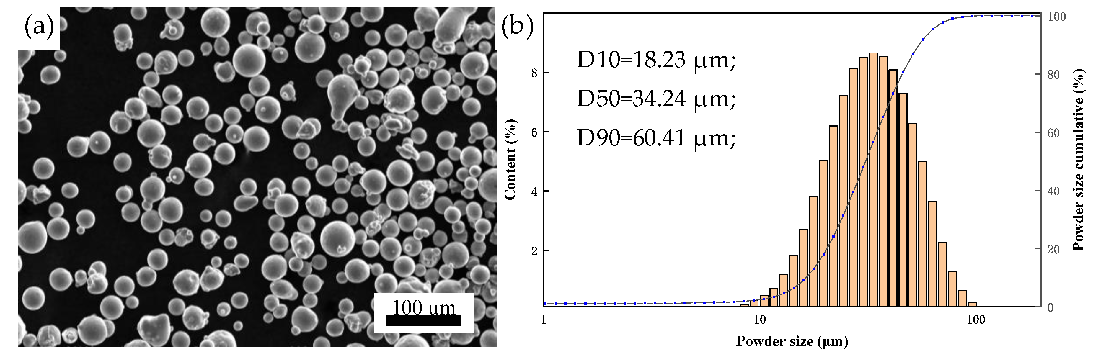
In this experiment, the raw material powder is prepared by inert gas atomized, and the powder size distribution and morphology of the powder are shown in the Figure 1. The size of the powder is in the range of 18–60 μm with an average value of around 34 μm. The sphericity of the powder is good, and the satellite powder is almost non-existent. The oxygen elements as well as other alloying elements are determined using the gas pulse infrared method (QB-QT-36-2014) as well as inductively coupled plasma atomic emission spectroscopy (ICP-AES, Burbach, North Rhine-Westphalia, Germany) and the results are shown in Table 1.
2.2. SLM Process
The SLM forming equipment uses the EP-M250 forming system(Beijing Eplus3D Technology Co., Ltd., Beijing, China), which has a maximum laser power of 500 W, a spot diameter of 70 μm and a forming chamber size of 258 mm × 258 mm × 350 mm. The 6061 alloys were selected as the deposition substrate due to its comparable expansion coefficient with the Al-Mn-Mg-Sc-Zr alloys. The machine default strip scan strategy with a scan direction rotation of 67° between consecutive layers was applied. In order to determine the relationship of cracking and the process parameters, simples with size of 60 mm × 12 mm × 12 mm are formed on substrate with preheating temperature of 140 °C, as shown in Figure 2. The chemical elemental composition of the formed samples is shown in Table 1.
The SLM process is an interaction between the laser and the powder. In addition to the properties of the powder used and the laser, there are many process parameters that affect the quality of the SLM formed alloy, such as volume energy density (VED), laser power (P), scanning speed (V), powder layer thickness (h), scanning track distance (L) and substrate preheating temperature. Different process parameters can also lead to large differences in the forming quality, surface topography, microstructure and mechanical properties of the alloy, so it is essential to optimize the process parameters. Some of the above processing parameters have the following mathematical relationship [23], as shown in Equation (1).
As known from the above equations, the VED can reflect the combined effect of P, V, L and h, while the L can be another object of study. In this study, the VED and P are successively analyzed as variables. The other processing parameters are set as constants, h = 0.03 mm; L = 0.1 mm; the substrate preheating temperature is 140 °C; and the scanning speed varies with the VED and P. First, this study fixes the P value at 410 W, then SLM forming is carried out for VED in the range of 118–143 J/mm3 with 4% increase each time (about 5 J/mm3) to find the best VED for the alloy. Second, the P was varied from 330 W to 430 W with a variable gradient of 20 W. Under the optimal VED, the optimization of the P is carried out. The detailed processing parameters are shown in Table 2.
2.3. Microstructure Characterization
In this study, the cracking behavior and densities of the formed samples are observed and analyzed using an Axiovert 200 MAT optical microscope (OM, Carl Zeiss AG, Oberkochen, Baden-Württemberg, Germany). The Archimedes drainage method is used to test the densities of the samples. The phase composition of the samples was determined by X’Pert Pro MPd polygrainline X-ray diffraction analyzer (XRD, Panalytical, almelo, Overijssel, Holland) from the Netherlands. The working tube voltage was 40 kV, the working current was 40 mA, and the scanning step was 0.033°.
The JSM-7900F field emission Scanning Electron Microscope (SEM, JEOL, Akishima, Tokyo, Japan) is used for the observation of porosity and microstructure, and the equipped Electron Backscattered Diffraction (EBSD, JEOL, Akishima, Tokyo, Japan), Back-Scattered Electron (BSE, JEOL, Akishima, Tokyo, Japan) and Electronic Channel Contrast (ECC, JEOL, Akishima, Tokyo, Japan) are used for the analysis of grain size and phase distribution, respectively. Samples for SEM were ground and then etched in a solution of 1% HF, 4% HNO3, and 95% H2O for 20 s to reveal the melt pool and grain boundaries. The FEI Tecnai F20 projection Energy Dispersive Spectroscopy (TEM, FEI, Hillsboro, OR, USA) and accompanying Energy Dispersive Spectroscopy (EDS, FEI, Hillsboro, OR, USA) are used to analyze the composition of the phases.
2.4. Mechanical Properties Analysis
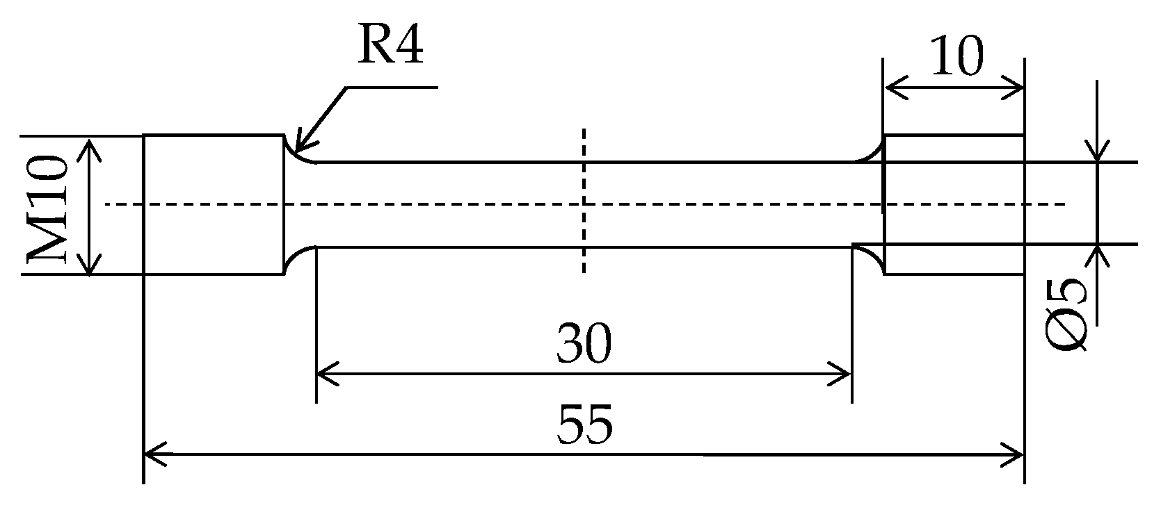
Tensile samples are processed in a direction parallel to the base plate and tested for mechanical properties on a micro-controlled electronic universal test machine at a rate of 0.45 mm/min, and test sample size according to ISO 6892-1-Metallic materials-Tensile testing-Part 1: Method of test at room temperature [24]. At least three samples are selected for each group of tensile tests and the tensile properties are averaged. The dimensions of the tensile samples are shown in Figure 3.
3. Results and Discussion
3.1. Optimization of Process Parameters
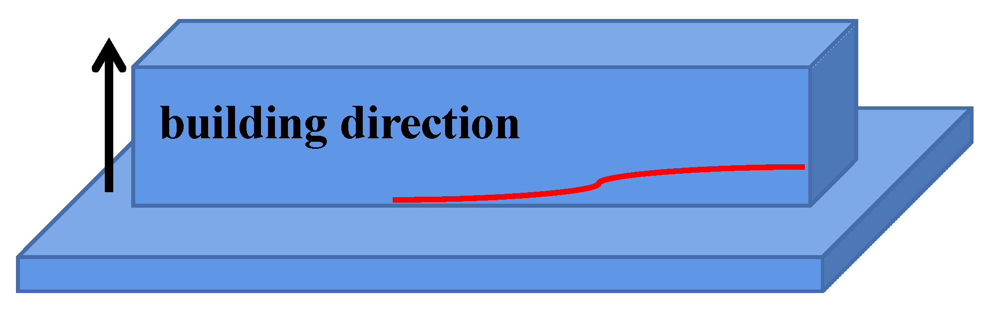
It is found that when the VED is low, the sample will crack. Surprisingly, each sample has cracks at the same position and there are many small cracks on the cross section, as shown in Figure 4. Therefore, subsequent experiments were conducted to analyze the surface of the crack.
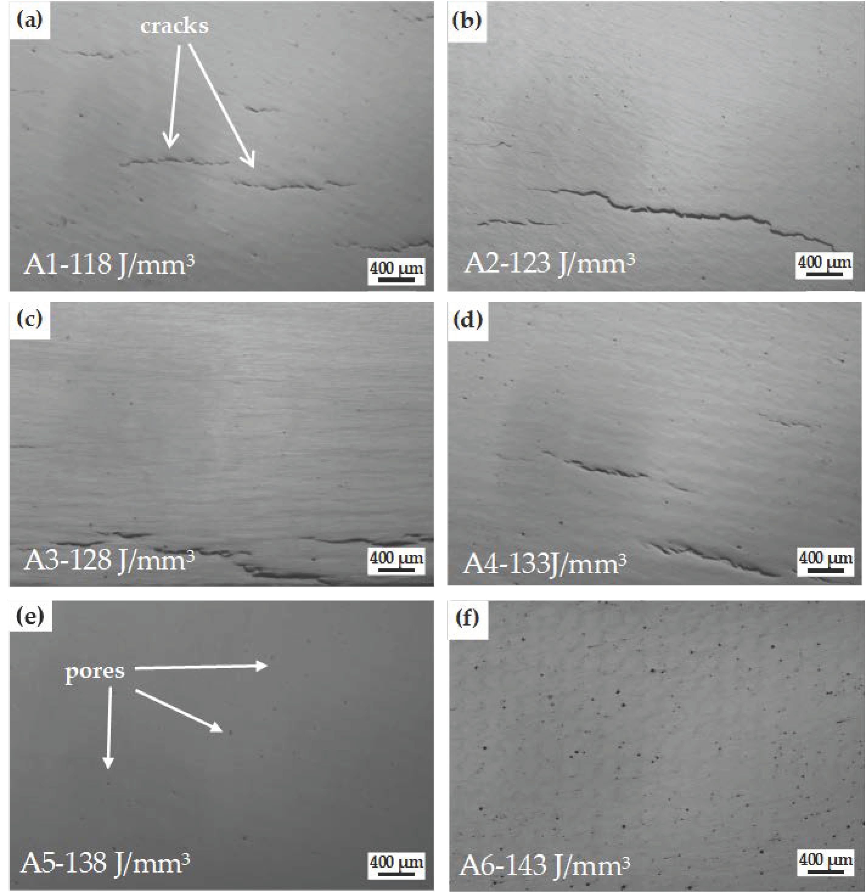
Figure 5 shows metallographic photographs of the formed samples at different energy densities. It shows that cracking occurs when the VED is 133 J/mm3 or less. Under the VED of 138 J/mm3, samples free of cracks can be obtained. When the VED increases further, it is found that the number and size of pores within the formed samples increased significantly, which would seriously affect the densities of the formed samples and deteriorate the mechanical properties, so the optimum VED is determined to be 138 J/mm3.
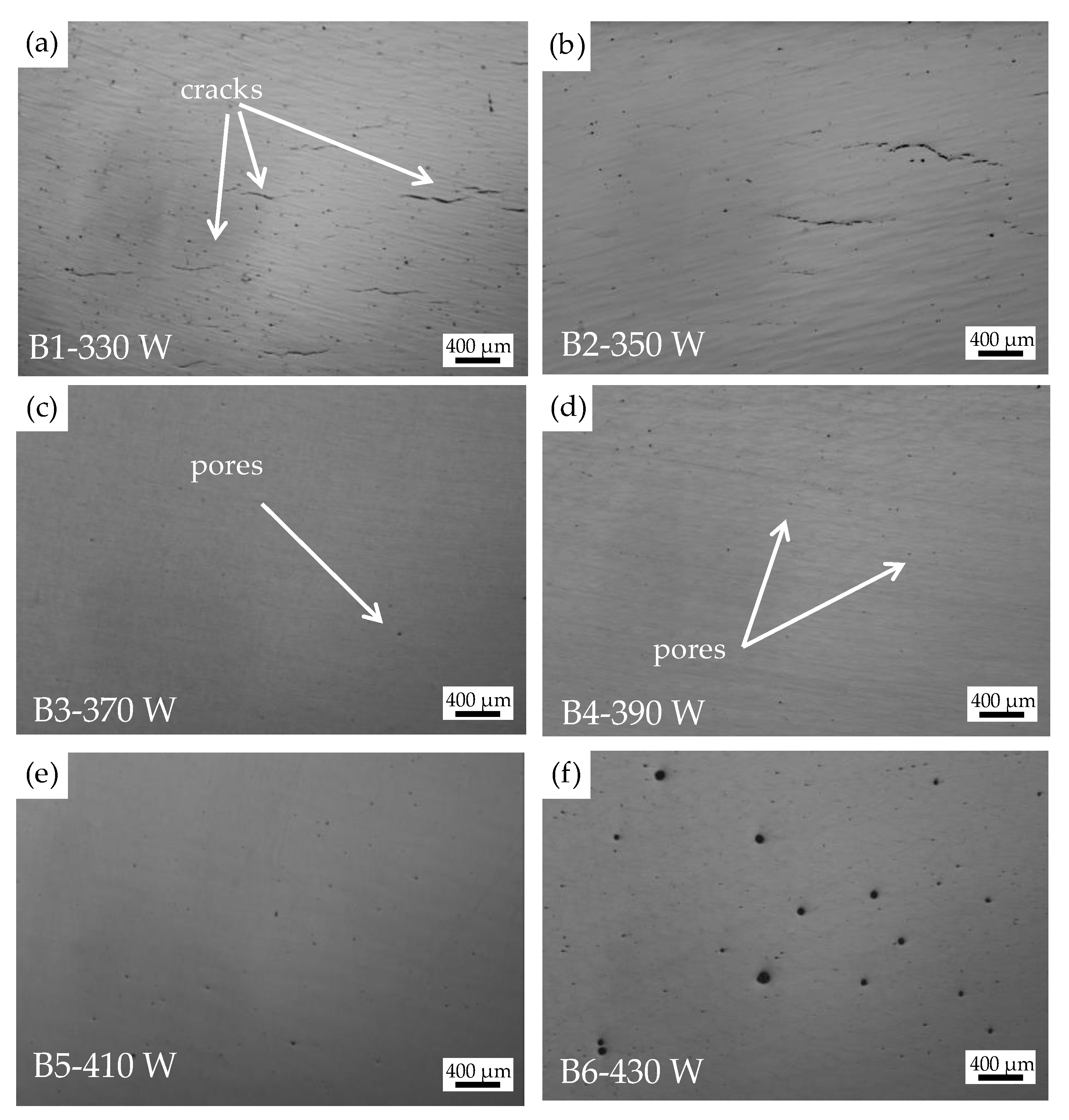
When the VED is set to 138 J/mm3, the formed samples still have small pores inside, which affected the density of the material. As the variable gradient in this experiment is only 5 J/mm3, the reason for the existing of large number of pores could be caused by a mismatch of other process parameters. Therefore, P is used as a variable for further experiments with a constant VED of 138 J/mm3. Figure 6 shows the metallographic morphology of the formed sample with different P. It is found that when the P is 350 W or less, the formed samples started to crack and the crack size is much reduced, indicating that the VED (138 J/mm3) is suitable for this alloy. The cracks disappeared when the P is higher than 370 W. However, as the P continued to increase, the number and size of the pores within the formed samples also increased. When the P reached 430 W, large pores are formed appeared as marked in Figure 6f. The higher P increases the laser impact on the melt pool and raises the temperature of the melt pool, leading to instability and increased evaporation of the melt pool, forming and typical evaporation pores. Such type of pores exhibits a near-round shape [20]. Chemical elemental analysis was carried out on the powder and samples and found a 14% decrease in the content of Mg elements. It is proved that higher molten pool temperature will lead to volatilization of low melting point elements, resulting in pores.
When the VED was 138 J/mm3 and the P was between 370 W and 410 W, crack-free and low porosity samples of Al-5.22Mn-1.16Mg-0.81Sc-0.46Zr alloys were ensured to be formed. The densities of the samples formed by the optimized processes are measured using the Archimedes drainage method, as shown in Table 3. Based on the results, the optimum forming process was finally determined to have a VED and P of 138 J/mm3 and 370 W, respectively.
3.2. Cracking Behavior
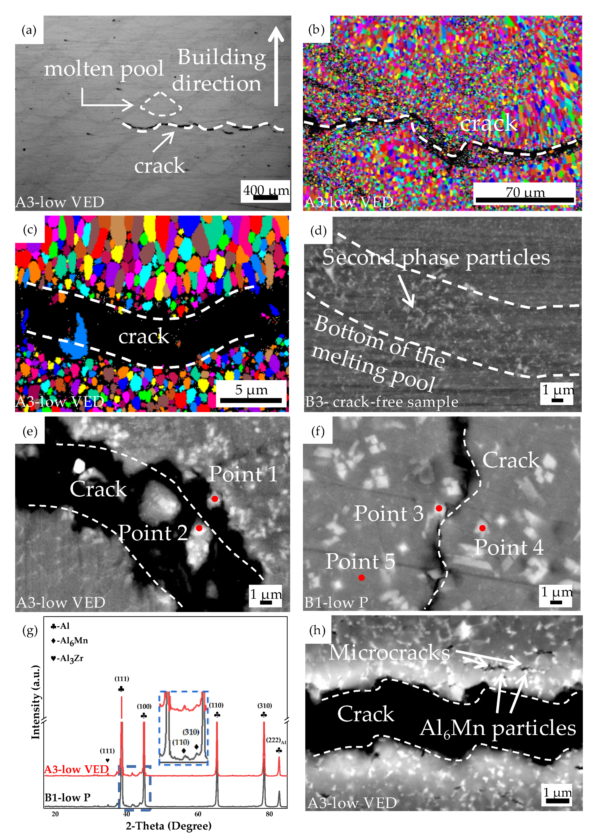
According to the analysis in 3.1, the size and number of cracks in alloy samples formed by different processes are different. The cracked samples are all caused by a mismatch between the two process parameters of lower VED or lower P. The low VED cracked samples (A3) and the low P cracked samples (B1) are further characterized their cracking behavior. In all the cracked samples, the cracks propagated in waves along the bottom of the melt pool, as shown in Figure 7a. In the EBSD image shown in Figure 7b,c, it is clear that the crack is extending along the bottom of the melt pool of the same forming layer. The bottom of the melt pool is composed of fine equiaxed grains. It has been proved that fine equiaxed grains have a strong shear capacity and that grain refining is considered an effective way to resist cracking, whereas in this study the crack initiation and propagation occurred within the fine grain region [15].
As shown Figure 7d, the second phases of the cracked-free sample (B3), showed little difference in size when compared to the lower VED cracked sample (A3, Figure 7e). However, the cracking occurred in the low VED samples. This is due to the lower VED resulting in a faster scanning speed, which reduces the laser interaction time with the powder and the melt pool presence time. The increased cooling rate on the one hand leads to an increase in the hot stress, and on the other hand to a decrease in the interlayer bonding of the sample due to a decrease in the energy intake. The effect of these two factors finally leads to the cracking of the alloy.
However, at the same VED, lower P can similarly cause cracking of the formed sample, as shown in Figure 7f. Lower P leads to an increase in the interaction time between the laser and the molten pool, and the size of the second phase formed increases significantly, with a regular angular shape. During SLM formation, the microscopic stress concentrations that form in the presence of higher thermal stresses may lead to cracking due to the formation of the angular shaped second phase.
In the Figure 7e,f, the second phase located around the crack (points 1–4) and the matrix (point 5) are analyzed using EDS and the results are shown in Table 4. The Mn element content in the matrix is significantly higher than the solid solution of Mn in the aluminum alloy (1.8 wt.%) [25], while the second phase appears more obviously enriched in Mn and Zr elements (e.g., point 2), and it can be judged that the second phase in this region is mainly enriched in Mn and contains little of the second phase composed of Sc and Zr. The second phases are likely to be Al6Mn and Al4Mn phases as judged from the Al-Mn phase diagram. XRD analysis of the cracked samples revealed that the Mn-rich phase in the alloy is Al6Mn (Figure 7g). The presence of the Al3Zr phase could also be detected, when combined with the Point 2 EDS analysis in Figure 7e, it is determined that a few Al3Zr particles are present around the crack.
It has been noted that for Al-Mn alloys formed by SLM, the Mn-rich phase will form an Al6Mn with a quasi-crystalline structure due to the rapid cooling of the SLM [26]. While the formation of the quasi-crystalline phase is considered to be a promising strategy for strengthening of aluminum alloys [27], although there are very brittle and hard at lower temperatures [28]. More Al6Mn phase formation will lead to cracking under hot stress and microscopic stress concentration around the sharp corner of the second phases with regular angular shape. We found a large number of Al6Mn particles at the grain boundaries of the cracked samples and found microcracking at the grain boundaries (Figure 7h). This verifies that Al6Mn has a high brittleness and hardness.
In summary, the addition of too much Mn to the alloy leads to a narrow range of forming processes and a high tendency to cracking during SLM. Appropriate reduction of the Mn element content is preferred for SLM forming of crack-free Al-Mn-Mg-Sc-Zr alloy parts.
3.3. Microstructure and Strengthening Mechanisms
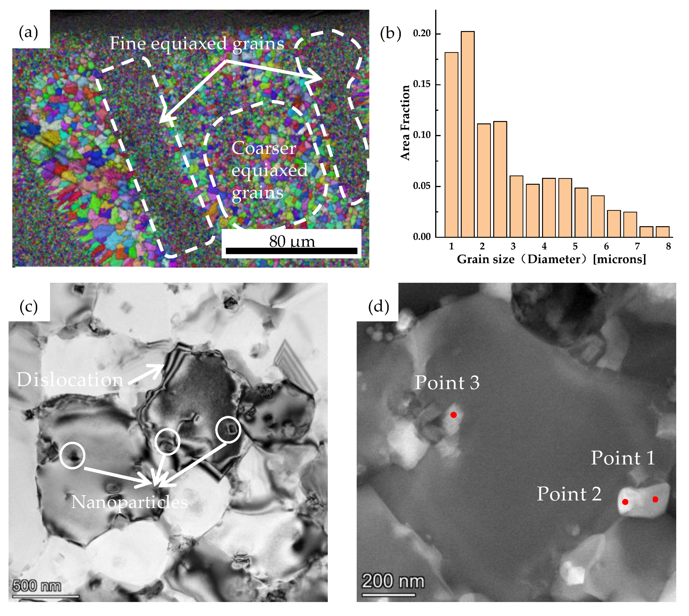
In this study, crack-free samples (B3) could be prepared at a VED and P of 138 J/mm3 and 370 W, respectively. The alloy was mainly found to be made up of fine equiaxed grains, as shown in Figure 8a,b. Statistical grain size shows that the equiaxed grains with no preferred orientation at the bottom of the melt pool are less than 2 μm, and the larger equiaxed grains within the melt pool are about 5 μm. Due to the addition of elements Sc and Mn, Al3Sc can act as a high-quality isomeric nucleation site, promoting the precipitation of α-Al grains with a grain refining effect. The Mn element without solid solution in the matrix will precipitate Al6Mn nanoparticles at the grain boundary, which effectively hinders the expansion of the grain boundary and inhibits the grain growth [29].
The fine grain structure ensures good combination of tensile strength and elongation. Under stress, the plastic deformation of adjacent grains of different orientations needs to be achieved by dislocations. Fine grains have a large number of grain boundaries, which act as a barrier to dislocations and inhibit deformation, resulting in the plastic deformation of one grain not being able to propagate directly to adjacent grains. It was found that a large number of dislocations were found at the grain boundaries, which is thought to have an extremely significant fine-grain strengthening effect, as shown in Figure 8c. According to the classical Hall-Petch relationship, sub-micron or even nano-sized grains will greatly increase the strength of the alloy [30]. There are two different sizes of equiaxed grains in this matrix, 5 μm and 2 μm, respectively. So, the following proposed modified Hall-Petch equation is used to estimate the corresponding strength increment [20], as shown in Equation (2).
where σ0 is the friction stress of pure aluminum (about 20 MPa), K is the Hall-Petch coefficient taken as 0.17 MPa [31], α is the area fraction of fine equiaxed grains (50% in this study based on EBSD statistics), d1 is the average grain size of equiaxed grains and d2 is the average columnar grain size (in width). The yield strength increment due to grain boundary strengthening is thereby calculated to be about 118 MPa.
According to reports, the SLM formed Al-Mn-Mg-Sc-Zr alloy contains a unique equiaxed-columnar bimodal grain structure with fine equiaxed grains at the bottom of the melt pool and elongated columnar grains inside the melt pool [32,33]. The reason for this difference may be related to the processing parameters used. The higher P and VED help to obtain near equiaxed grain structures [34]. This structure helps to reduce the anisotropy of the mechanical properties of the alloy material.
At the same time, nanoscale second phase particles can be found distributed inside the grain or at grain boundaries (Figure 8c). This may be related to the metallurgical properties of the SLM process. The higher cooling rates offer the possibility of solid solution of the elements Mn, Mg, Sc and Zr in the alloy matrix. The solid solution of a large number of alloying elements leads to lattice distortion of the matrix, which impedes dislocation movement and further increases the strength of the alloy. Moreover, during the SLM process, each layer of forming will have a thermal effect on the already solidified alloy. This results in the precipitation of a second phase of nanoparticles in the matrix. As shown in Figure 8d, the nanoparticles are distributed at the grain boundaries, and two distinct phases exist as judged by the difference in morphology. The nanoparticles are derived from EDS analysis (Table 5), which identified the two particles as Al6Mn and Al3(Sc, Zr) phases, respectively. Due to the dispersed distribution of such nanoparticles, the precipitation strengthening effect of the alloy can be significantly improved [35]. The motion of dislocations can be impeded due to the modulus differences between the precipitates and the surrounding Al matrix and thus significantly increase the strength of the alloy [36,37].
The main strengthening mechanisms that contribute to the high strength of the SLM Al-Mn-Mg-Sc-Zr alloy arise from fine grain strengthening, solid solution strengthening, and precipitation hardening. The interactions between the different strengthening mechanisms are often very complex. What is certain, however, is that the alloy should have relatively good mechanical properties.
3.4. Mechanical Properties Test
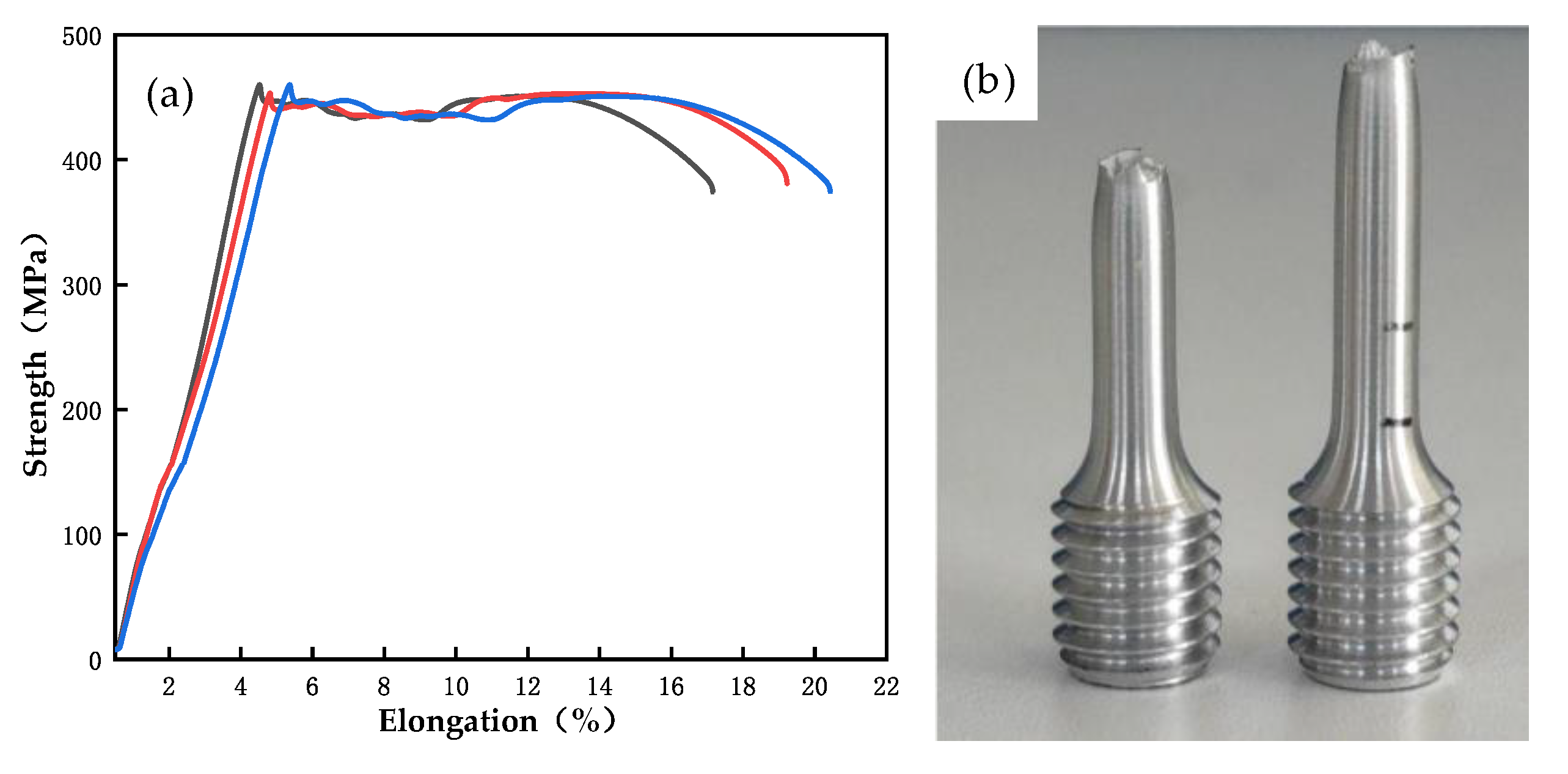
The typical stress-strain curves of crack-free samples(B3) are shown in Figure 9a. For the as-deposited samples, the tensile strength and elongation are 455.2 ± 0.7 MPa and 15.4 ± 0.3%, respectively. As shown in Figure 9b, the fracture surface is parallel to the maximum shear stress and has an angle of 45° with the principal stress, which has obvious necking phenomenon and is considered as ductile fracture. Compared with the Al-Mn-Mg-Sc-Zr alloy with similar composition (438 ± 3 MPa and 19 ± 3%), the tensile strength of the alloy is higher [20].
This is mainly due to the high elemental content of manganese in this study and the large number of Al6Mn nanoparticles precipitated at grain boundaries or within the grain, thus enhancing the effect of precipitation strengthening to improve the strength of the alloy. In Chapter 3.2 it was found that an increase in the elemental manganese content leads to the precipitation of a significant amount of Al6Mn second phase in the deposited alloy, these undoubtedly increase the risk of cracking during forming and lead to a reduction in the range of process parameters. Therefore, on the basis of this study, we hope that the manganese content should be reduced appropriately to improve the formability of the alloy and to prepare Al-Mn alloy parts with complex shapes.
4. Conclusions
In this study, the SLM of Al-Mn-Mg-Sc-Zr alloy is investigated, with a particular emphasis on the optimization processing parameters, microstructure and mechanical properties. The following conclusions are drawn from the findings:
- By optimizing the SLM forming process, crack-free samples of the Al-Mn-Mg-Sc-Zr alloy were finally prepared at a volume energy density of 138 J/mm3 and a laser power of 370–410 W. The highest relative density of the samples was achieved when the laser power was 370 W. The alloy formed by this processing has a dense structure and good mechanical property, which have a tensile strength of 455 MPa and an elongation of 15.4% at room temperature. This performance is higher than previously reported aluminum alloys.
- The increase of volume energy density will lead to the increase of porosity and the decrease of relative density. The lower volume energy density will lead to cracking of the alloy. The lower volume energy density finally leads to an increase in high thermal stresses and a decrease in interlaminar bonding, which leads to cracking. Keep the volume energy density constant and adjust the laser power. It can be found that increasing the laser power also increases the porosity, while decreasing it leads to cracking of the alloy. Reducing the laser power will increase the interaction time between laser and powder, reduce the cooling rate, and precipitate coarse angular Al6Mn phase. Thus increases the risk of microscopic stress concentrations, which can lead to cracking.
- The supersaturated solid solution phase obtained by the high cooling rate. High Sc and Mn contents provide more nucleation sites during alloy solidification. Combined with the high cooling rate of SLM, an excellent grain refinement effect is achieved. The grain size of the equiaxial grains at the bottom of the molten pool and inside the molten pool is reduced to 2 μm and 5 μm, respectively. There are a large number of finely dispersed Al6Mn and Al3(Sc, Zr) phases inside and between grains. Various strengthening mechanisms such as solid solution strengthening, fine grain strengthening and precipitation strengthening ensure that the alloy has high mechanical properties.
This research provides experience and guidance for high-strength aluminum alloy net shape forming complex parts, and promotes the production of selective laser melted aluminum alloy parts to meet the growing needs of the industry.
Author Contributions
Z.Z., W.P. and Y.Z. conceived, designed and carried out the experiments; Z.Z. wrote the main manuscript; W.P. and B.L. assisted with carrying out the experiments; Y.L. and Y.Z. reviewed the manuscript. All authors have read and agreed to the published version of the manuscript.
Funding
This research received no external funding.
Institutional Review Board Statement
Not applicable.
Informed Consent Statement
Not applicable.
Data Availability Statement
Date is contained within the article.
Acknowledgments
The financial support by GRINM Metal Composites Technology Co., Ltd. and research platform support by National Engineering and Technology Research Center for Non-ferrous Metal Matrix Composites, GRINM Group Co., Ltd. is greatly acknowledged.
Conflicts of Interest
The authors declare no conflict of interest.
References
- DebRoy, T.; Wei, H.L.; Zuback, J.S.; Mukherjee, T.; Elmer, J.W.; Milewski, J.O.; Beese, A.M.; Wilson-Heid, A.; De, A.; Zhang, W. Additive manufacturing of metallic components–Process, structure and properties. Prog. Mater. Sci. 2018, 92, 112–224. [Google Scholar] [CrossRef]
- Chen, L.-Y.; Liang, S.-X.; Liu, Y.; Zhang, L.-C. Additive manufacturing of metallic lattice structures: Unconstrained design, accurate fabrication, fascinated performances, and challenges. Mater. Sci. Eng. R Rep. 2021, 146, 100648. [Google Scholar] [CrossRef]
- Olakanmi, E.O.; Cochrane, R.F.; Dalgarno, K.W. A review on selective laser sintering/melting (SLS/SLM) of aluminium alloy powders: Processing, microstructure, and properties. Prog. Mater. Sci. 2015, 74, 401–477. [Google Scholar] [CrossRef]
- Derekar, K.S.; Addison, A.; Joshi, S.S.; Zhang, X.; Lawrence, J.; Xu, L.; Melton, G.; Griffiths, D. Effect of pulsed metal inert gas (pulsed-MIG) and cold metal transfer (CMT) techniques on hydrogen dissolution in wire arc additive manufacturing (WAAM) of aluminium. Int. J. Adv. Manuf. Technol. 2020, 107, 311–331. [Google Scholar] [CrossRef]
- Aldalur, E.; Suárez, A.; Veiga, F. Metal transfer modes for Wire Arc Additive Manufacturing Al-Mg alloys: Influence of heat input in microstructure and porosity. J. Mater. Process. Technol. 2021, 297, 117271. [Google Scholar] [CrossRef]
- Kotadia, H.R.; Gibbons, G.; Das, A.; Howes, P.D. A review of Laser Powder Bed Fusion Additive Manufacturing of aluminum alloys: Microstructure and properties. Addit. Manuf. 2021, 46, 102–155. [Google Scholar] [CrossRef]
- Zhang, J.; Song, B.; Wei, Q.; Bourell, D.; Shi, Y. A review of selective laser melting of aluminum alloys: Processing, microstructure, property and developing trends. J. Mater. Sci. Technol. 2019, 35, 270–284. [Google Scholar] [CrossRef]
- Roth, C.C.; Tancogne-Dejean, T.; Mohr, D. Plasticity and fracture of cast and SLM AlSi10Mg: High-throughput testing and modeling. Addit. Manuf. 2021, 43, 101998. [Google Scholar] [CrossRef]
- Han, J.-Q.; Wang, J.-S.; Zhang, M.-S.; Niu, K.-M. Relationship between amounts of low-melting-point eutectics and hot tearing susceptibility of ternary Al−Cu−Mg alloys during solidification. Trans. Nonferrous Met. Soc. China 2020, 30, 2311–2325. [Google Scholar] [CrossRef]
- Liu, P.; Hu, J.-Y.; Li, H.-X.; Sun, S.-Y.; Zhang, Y.-B. Effect of heat treatment on microstructure, hardness and corrosion resistance of 7075 Al alloys fabricated by SLM. J. Manuf. Process. 2020, 60, 578–585. [Google Scholar] [CrossRef]
- Zhang, H.; Zhu, H.; Nie, X.; Yin, J.; Hu, Z.; Zeng, X. Effect of Zirconium addition on crack, microstructure and mechanical behavior of selective laser melted Al-Cu-Mg alloy. Scr. Mater. 2017, 134, 6–10. [Google Scholar] [CrossRef]
- Martin, J.H.; Yahata, B.D.; Hundley, J.M.; Mayer, J.A.; Schaedler, T.A.; Pollock, T.M. 3D printing of high-strength aluminium alloys. Nature 2017, 549, 365–369. [Google Scholar] [CrossRef]
- Otani, Y.; Sasaki, S. Effects of the addition of silicon to 7075 aluminum alloy on microstructure, mechanical properties, and selective laser melting processability. Mater. Sci. Eng. A 2020, 777, 139079. [Google Scholar] [CrossRef]
- Opprecht, M.; Garandet, J.-P.; Roux, G.; Flament, C.; Soulier, M. A solution to the hot cracking problem for aluminium alloys manufactured by laser beam melting. Acta Mater. 2020, 197, 40–53. [Google Scholar] [CrossRef]
- Qbau, N.; Nam, N.D.; Ca, N.X.; Hien, N.T. The crack healing effect of scandium in aluminum alloys during laser additive manufacturing. J. Manuf. Process. 2020, 50, 241–246. [Google Scholar] [CrossRef]
- Geng, Y.; Jia, C.; Xu, J.; Zhang, Z.; Ju, H.; Wang, D.; Yu, L. Selective laser melting of a novel high-strength Er- and Zr-modified Al-Mn-Mg alloy. Mater. Lett. 2022, 313, 131762. [Google Scholar] [CrossRef]
- Jia, Q.; Rometsch, P.; Cao, S.; Zhang, K.; Huang, A.; Wu, X. Characterisation of AlScZr and AlErZr alloys processed by rapid laser melting. Scr. Mater. 2018, 151, 42–46. [Google Scholar] [CrossRef]
- Schmidtke, K.; Palm, F.; Hawkins, A.; Emmelmann, C. Process and Mechanical Properties: Applicability of a Scandium modified Al-alloy for Laser Additive Manufacturing. Phys. Procedia 2011, 12, 369–374. [Google Scholar] [CrossRef] [Green Version]
- Spierings, A.B.; Dawson, K.; Voegtlin, M.; Palm, F.; Uggowitzer, P.J. Microstructure and mechanical properties of as-processed scandium-modified aluminium using selective laser melting. CIRP Ann. 2016, 65, 213–216. [Google Scholar] [CrossRef]
- Jia, Q.; Rometsch, P.; Kürnsteiner, P.; Chao, Q.; Huang, A.; Weyland, M.; Bourgeois, L.; Wu, X. Selective laser melting of a high strength Al Mn Sc alloy: Alloy design and strengthening mechanisms. Acta Mater. 2019, 171, 108–118. [Google Scholar] [CrossRef]
- Jia, Q.; Rometsch, P.; Cao, S.; Zhang, K.; Wu, X. Towards a high strength aluminium alloy development methodology for selective laser melting. Mater. Des. 2019, 174, 107775. [Google Scholar] [CrossRef]
- Geng, Y.; Tang, H.; Xu, J.; Zhang, Z.; Xiao, Y.; Wu, Y. Strengthening mechanisms of high-performance Al-Mn-Mg-Sc-Zr alloy fabricated by selective laser melting. Sci. China Mater. 2021, 64, 3131–3137. [Google Scholar] [CrossRef]
- Galy, C.; Le Guen, E.; Lacoste, E.; Arvieu, C. Main defects observed in aluminum alloy parts produced by SLM: From causes to consequences. Addit. Manuf. 2018, 22, 165–175. [Google Scholar] [CrossRef]
- ISO 6892-1. 2019. Available online: https://www.iso.org/standard/78322.html (accessed on 1 November 2019).
- Du, Y.; Wang, J.; Zhao, J.; Schuster, J.C.; Weitzer, F.; Schmid-Fetzer, R.; Ohno, M.; Xu, H.; Liu, Z.-K.; Shang, S.-L.; et al. Reassessment of the Al–Mn system and a thermodynamic description of the Al–Mg–Mn system. Int. J. Mater. Res. 2007, 98, 855–871. [Google Scholar] [CrossRef]
- Bayoumy, D.; Schliephake, D.; Dietrich, S.; Wu, X.H.; Zhu, Y.M.; Huang, A.J. Intensive processing optimization for achieving strong and ductile Al-Mn-Mg-Sc-Zr alloy produced by selective laser melting. Mater. Des. 2021, 198, 109317. [Google Scholar] [CrossRef]
- Stan-Głowińska, K.; Rogal, Ł.; Góral, A.; Wierzbicka-Miernik, A.; Wojewoda-Budka, J.; Schell, N.; Lityńska-Dobrzyńska, L. Formation of a quasicrystalline phase in Al–Mn base alloys cast at intermediate cooling rates. J. Mater. Sci. 2017, 52, 7794–7807. [Google Scholar] [CrossRef] [Green Version]
- Pedrazzini, S.; Galano, M.; Audebert, F.; Collins, D.M.; Hofmann, F.; Abbey, B.; Korsunsky, A.M.; Lieblich, M.; Escorial, A.G.; Smith, G.D.W. Strengthening mechanisms in an Al-Fe-Cr-Ti nano-quasicrystalline alloy and composites. Mater. Sci. Eng. A 2016, 672, 175–183. [Google Scholar] [CrossRef] [Green Version]
- Cao, P.; Qian, M.; StJohn, D.H. Effect of manganese on grain refinement of Mg–Al based alloys. Scr. Mater. 2006, 54, 1853–1858. [Google Scholar] [CrossRef]
- Hu, J.; Shi, Y.N.; Sauvage, X.; Sha, G.; Lu, K. Grain boundary stability governs hardening and softening in ex-tremely fine nanograined metals. Science 2017, 355, 1292–1296. [Google Scholar] [CrossRef]
- Croteau, J.R.; Griffiths, S.; Rossell, M.D.; Leinenbach, C.; Kenel, C.; Jansen, V.; Seidman, D.N.; Dunand, D.C.; Vo, N.Q. Microstructure and mechanical properties of Al-Mg-Zr alloys processed by selective laser melting. Acta Mater. 2018, 153, 35–44. [Google Scholar] [CrossRef]
- Du, L.; Ke, L.; Xiao, M.; Dou, E.; Luo, Z.; Chen, Y.; Lai, C. Densification, microstructure and properties of Sc and Zr modified Al-Mn alloy prepared by selective laser melting. Opt. Laser Technol. 2022, 148, 107703. [Google Scholar] [CrossRef]
- Jia, Q.; Zhang, F.; Rometsch, P.; Li, J.; Mata, J.; Weyland, M.; Bourgeois, L.; Sui, M.; Wu, X. Precipitation kinetics, microstructure evolution and mechanical behavior of a developed Al–Mn–Sc alloy fabricated by selective laser melting. Acta Mater. 2020, 193, 239–251. [Google Scholar] [CrossRef]
- Yang, K.V.; Shi, Y.; Palm, F.; Wu, X.; Rometsch, P. Columnar to equiaxed transition in Al-Mg(-Sc)-Zr alloys produced by selective laser melting. Scr. Mater. 2018, 145, 113–117. [Google Scholar] [CrossRef]
- Rogachev, S.O.; Naumova, E.A.; Karelin, R.D.; Andreev, V.A.; Perkas, M.M.; Yusupov, V.S.; Khatkevich, V.M. Effect of Warm Equal-Channel Angular Pressing on the Structure and Mechanical Properties of Al–Mg–Ca–Mn–Fe–Zr Alloy. Phys. Met. Met. 2021, 122, 67–73. [Google Scholar] [CrossRef]
- Fink, W.L. Precipitation Hardening. J. Appl. Phys. 1942, 13, 75–83. [Google Scholar] [CrossRef]
- Wang, Q.; Li, Z.; Pang, S.; Li, X.; Dong, C.; Liaw, P.K. Coherent Precipitation and Strengthening in Compositionally Complex Alloys: A Review. Entropy 2018, 20, 878. [Google Scholar] [CrossRef] [Green Version]
Figure 1.
Powder analyze results: (a) powder morphology; (b) powder size distribution diagram.

Figure 2.
SLM formed samples.

Figure 3.
Shape and dimensions of the tensile sample (mm).

Figure 4.
Schematic diagram of crack location (Red curve represents the location of major cracks).

Figure 5.
Metallographic photographs of samples formed with different volume energy densities: (a) 118 J/mm3, (b) 123 J/mm3, (c) 128 J/mm3, (d) 133 J/mm3, (e) 138 J/mm3, (f) 143 J/mm3.
Figure 5.
Metallographic photographs of samples formed with different volume energy densities: (a) 118 J/mm3, (b) 123 J/mm3, (c) 128 J/mm3, (d) 133 J/mm3, (e) 138 J/mm3, (f) 143 J/mm3.

Figure 6.
Metallographic photographs of formed samples at different P: (a) 330 W, (b) 350 W, (c) 370 W, (d) 390 W, (e) 410 W, (f) 430 W.
Figure 6.
Metallographic photographs of formed samples at different P: (a) 330 W, (b) 350 W, (c) 370 W, (d) 390 W, (e) 410 W, (f) 430 W.

Figure 7.
Cracking analysis: (a) OM image of A3, (b) EBSD images of A3, (c) EBSD images of A3, (d) BSE image of B3, (e) BSE image of A3, (f) BSE image of B1, (g) XRD analysis of A3 and B1, (h) ECC image of A3.
Figure 7.
Cracking analysis: (a) OM image of A3, (b) EBSD images of A3, (c) EBSD images of A3, (d) BSE image of B3, (e) BSE image of A3, (f) BSE image of B1, (g) XRD analysis of A3 and B1, (h) ECC image of A3.

Figure 8.
Microscopic analysis of formed sample B3: (a) EBSD image. (b) Grain Size Statistics. (c) Bright-field TEM image, (d) Dark-field TEM image.
Figure 8.
Microscopic analysis of formed sample B3: (a) EBSD image. (b) Grain Size Statistics. (c) Bright-field TEM image, (d) Dark-field TEM image.

Figure 9.
Mechanical performance analysis: (a) Engineering stress-strain curves of the as-deposited samples; (b) Tensile fractural sample.
Figure 9.
Mechanical performance analysis: (a) Engineering stress-strain curves of the as-deposited samples; (b) Tensile fractural sample.


Table 1.
Chemical element content of powder and samples for SLM (wt.%).
| Element | Al | Mn | Mg | Sc | Zr | O |
|---|---|---|---|---|---|---|
| powder | Bal. | 5.22 | 1.16 | 0.81 | 0.46 | 0.01 |
| sample | Bal. | 5.22 | 1.00 | 0.82 | 0.46 | 0.01 |
Table 2.
Processing parameters of SLM.
| No. | Laser Power (P)W | Volume Energy Density (VED) J/mm3 | Scan Speed (V) mm/s | Scanning Track Distance (h) mm | Powder Layer Thickness (h) mm |
|---|---|---|---|---|---|
| A1 | 410 | 118 | 1158 | 0.1 | 0.03 |
| A2 | 410 | 123 | 1111 | 0.1 | 0.03 |
| A3 | 410 | 128 | 1068 | 0.1 | 0.03 |
| A4 | 410 | 133 | 1028 | 0.1 | 0.03 |
| A5 | 410 | 138 | 990 | 0.1 | 0.03 |
| A6 | 410 | 143 | 956 | 0.1 | 0.03 |
| B1 | 330 | 138 | 797 | 0.1 | 0.03 |
| B2 | 350 | 138 | 845 | 0.1 | 0.03 |
| B3 | 370 | 138 | 894 | 0.1 | 0.03 |
| B4 | 390 | 138 | 942 | 0.1 | 0.03 |
| B5 | 410 | 138 | 990 | 0.1 | 0.03 |
| B6 | 430 | 138 | 1039 | 0.1 | 0.03 |
Table 3.
Densities of formed samples.
| Process Parameters | Actual Density (g/cm3) | Relative Density (%) |
|---|---|---|
| VED = 138 J/mm3 and P = 410 W | 2.7506 | 98.59 |
| VED = 138 J/mm3 and P = 390 W | 2.7672 | 99.18 |
| VED = 138 J/mm3 and P = 370 W | 2.7704 | 99.30 |
Table 4.
EDS analysis of the second phases around the cracks shown in Figure 7e,f. (wt.%).
Table 4.
EDS analysis of the second phases around the cracks shown in Figure 7e,f. (wt.%).
| Element | Point 1 | Point 2 | Point 3 | Point 4 | Point 5 |
|---|---|---|---|---|---|
| Al | 87.99 | 84.49 | 87.33 | 86.45 | 92.69 |
| Mn | 8.36 | 10.2 | 9.78 | 10.28 | 5.40 |
| Mg | 1.73 | 2.09 | 1.72 | 1.85 | 0.62 |
| Sc | 1.03 | 1.05 | 0.5 | 0.7 | 0.72 |
| Zr | 0.89 | 2.16 | 0.67 | 0.72 | 0.58 |
Table 5.
EDS analysis of the second phases around grain boundaries shown in Figure 9d. (wt.%).
Table 5.
EDS analysis of the second phases around grain boundaries shown in Figure 9d. (wt.%).
| Element | Point 1 | Point 2 | Point 3 |
|---|---|---|---|
| Al | 78.75 | 72.39 | 78.56 |
| Mn | 20.13 | 27.15 | 1.00 |
| Mg | 0.81 | 0.22 | 0.92 |
| Sc | 0.01 | 0.04 | 9.89 |
| Zr | 0.30 | 0.20 | 9.64 |
Publisher’s Note: MDPI stays neutral with regard to jurisdictional claims in published maps and institutional affiliations. |
© 2022 by the authors. Licensee MDPI, Basel, Switzerland. This article is an open access article distributed under the terms and conditions of the Creative Commons Attribution (CC BY) license (https://creativecommons.org/licenses/by/4.0/).
Share and Cite
MDPI and ACS Style
Zhai, Z.; Pan, W.; Liang, B.; Liu, Y.; Zhang, Y. Cracking Behavior, Microstructure and Properties of Selective Laser Melted Al-Mn-Mg-Sc-Zr Alloy. Crystals 2022, 12, 565. https://0-doi-org.brum.beds.ac.uk/10.3390/cryst12040565
AMA Style
Zhai Z, Pan W, Liang B, Liu Y, Zhang Y. Cracking Behavior, Microstructure and Properties of Selective Laser Melted Al-Mn-Mg-Sc-Zr Alloy. Crystals. 2022; 12(4):565. https://0-doi-org.brum.beds.ac.uk/10.3390/cryst12040565
Chicago/Turabian StyleZhai, Ziyu, Wei Pan, Bo Liang, Yantao Liu, and Yongzhong Zhang. 2022. "Cracking Behavior, Microstructure and Properties of Selective Laser Melted Al-Mn-Mg-Sc-Zr Alloy" Crystals 12, no. 4: 565. https://0-doi-org.brum.beds.ac.uk/10.3390/cryst12040565
Note that from the first issue of 2016, this journal uses article numbers instead of page numbers. See further details here.