Article

Surface Quality Experimental Study on Rotary Ultrasonic Machining of Honeycomb Composites with a Circular Knife Cutting Tool

School of Mechanical and Automotive Engineering, Shanghai University of Engineering Science, Shanghai 201620, China
*
Author to whom correspondence should be addressed.
Submission received: 21 April 2022 / Revised: 7 May 2022 / Accepted: 11 May 2022 / Published: 19 May 2022
(This article belongs to the Special Issue Processing Technology of Brittle Crystal Materials)

Abstract

:
Honeycomb composites (HCs) are diversely employed in aerospace, national defense and other fields owing to their remarkable spatial geometry and excellent mechanical properties. Their complex hexagonal cell structure and heterogeneous material properties cause major problems when implementing high-quality processing. Surface defects generated by processing will reduce the capability and service lifespan of the honeycomb sandwich structure. Therefore, the high quality of HCs is a topic of close attention for researchers. In this paper, the consequences of different cutting parameters of rotary ultrasonic machining (RUM) on surface quality with an ultrasonic circular knife (UCK) were studied through multiple groups of single-factor and orthogonal experiments with two-factors/four-levels and one-factor/three-levels. The single factor experiment was used to explain the effect that the degree of cutting parameters has on surface quality, and the orthogonal experiments were applied to explain the interaction between the processing parameters and the influence law of each factor on surface quality. Therefore, the reasonable cutting parameters of HCs were determined through experimental results to provide guidance for the realization of the precise and efficient machining of HCs. This study can provide a basis for the subsequent comprehensive consideration of various factors to achieve high-quality machining of HCs.

1. Introduction

Compared with other structures of the same material, the honeycomb sandwich structure has excellent spatial geometry and mechanical properties [1]. The honeycomb core sandwich structure is a sandwich composite material formed by connecting the honeycomb core and the upper and lower panels with adhesive and curing. It has high stiffness along the axial direction of the cell, therefore, it can bear an impact force on the sandwich structure [2]. However, honeycomb is a typical thin-walled porous structure. The particularity of its structure leads to low in-plane rigidity of the honeycomb core, which is prone to various defects during processing and reduces the performance and service life [3,4,5,6,7,8,9]. The mechanical properties largely rely on honeycomb composite core density, quality and the bonding strength between the core and the panel [1,10]. Therefore, the influence of machining defects on the honeycomb core and its mechanical properties is a key factor to be considered. Consequently, it is significant to research the morphology features of the honeycomb composite (HCs) core and the effect of cutting parameters on HCs core surface quality.
Due to the merits of high processing efficiency and convenient manufacturing of processing equipment, conventional high-speed CNC milling was widely used in honeycomb core material processing. However, traditional processing methods cause the following problems, such as poor processing quality, harsh processing environment, tool wear and so on [11,12]. Thence, rotary ultrasonic machining technology (RUM) was applied to solve the shortcomings of traditional technologies for HC core machining. As a rapidly developing processing technology, RUM technology has been more and more widely employed in the processing of various materials such as composites [13,14,15,16], crystal [17], ceramics [18,19], titanium alloys [20,21], glass and aluminum alloys [22,23,24,25]. In the past, most scholars have carried out research on RUM technology, mainly including the design of the ultrasonic system and ultrasonic cutting tools, the degree of effect of the independent variable cutting parameters on the surface quality of the dependent variable, etc. Xiang et al. [26] proposed that the ultrasonic longitudinal–torsional composite vibration machining method has excellent performance and better surface morphology compared with the transonic longitudinal vibration machining method by analyzing the kinematics of the two processing methods. Xia et al. [27] optimized the structure of ultrasonic cutting tools and explored the influence of distinct tool structure parameters on the machining efficiency of the Nomex honeycomb composite core. Sun et al. [28] concluded that the introduction of RUM technology can significantly reduce the cutting generation of tool cutting forces during machining, thereby reducing the deformation of aluminum honeycomb core walls, resulting in high-quality workpieces. Ahmad et al. [29] conducted a comprehensive review on machining technologies for Nomex HC and Ahmad et al. [30] discussed the influence of different structural parameters of the UCK cutting tool used in machining on ultrasonic amplitude as well as the resonant frequency. Ahmad et al. [31] also researched RUM characteristics of Nomex HCs by a series of UCK cutting tools through a series of controlled variable experiments and orthogonal experimental methods. Asmael et al. [32] reported a review on carbon-fiber-reinforced plastic composites by ultrasonic machining. Hu et al. [33] proposed a cutting force model of a triangular blade on honeycomb composites by ultrasonic machining. Cao et al. [34] constructed a three-dimensional finite element model through ABAQUS to analyze the ultrasonic vibration-assisted tool of the Nomex honeycomb core.
In this paper, a group of single-factor experiments and orthogonal experiments of RUM technology with a circular ultrasonic knife for HC core in terms of the aluminum honeycomb core and the Nomex honeycomb core workpiece were conducted to discuss the effect of different processing parameters, i.e., tool feed rate, tool cutting width, ultrasonic spindle speed on surface quality. Then, we further analyzed the significance of different cutting parameters on surface quality through orthogonal experiments developed in this study. Therefore, the framework of this paper is arranged as follows. The experimental synopsis is introduced in Section 2. Section 3 shows the experimental program. The phenomenon and discussion are presented in Section 4. The next section, namely, Section 5, summarizes this paper.

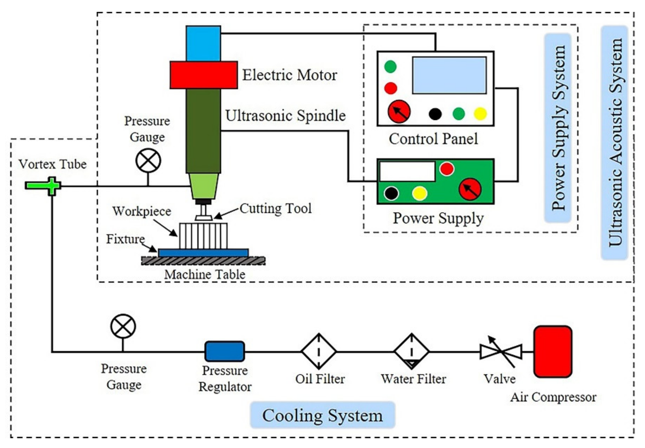
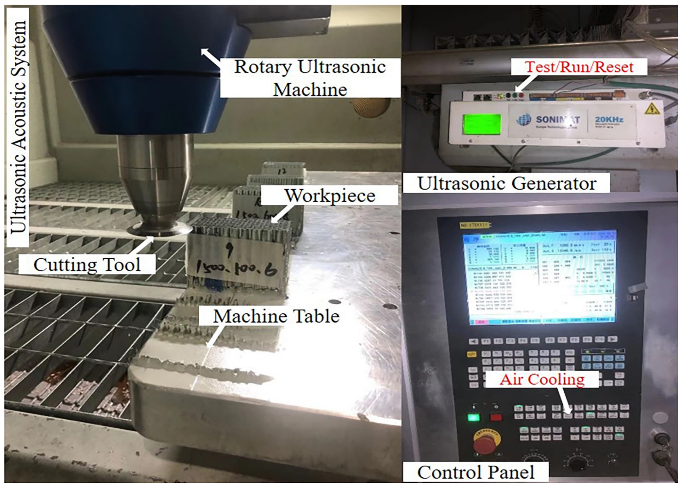
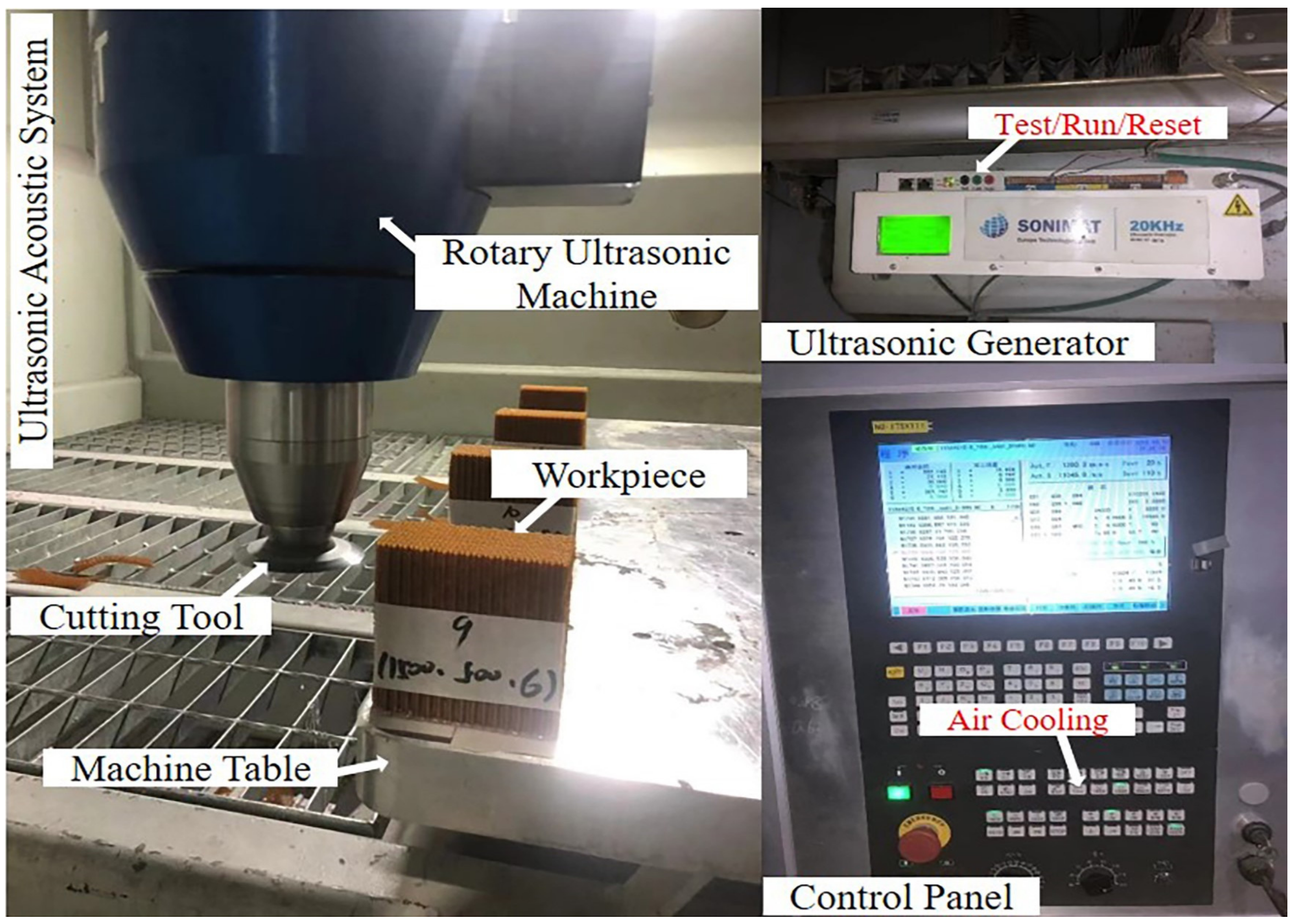
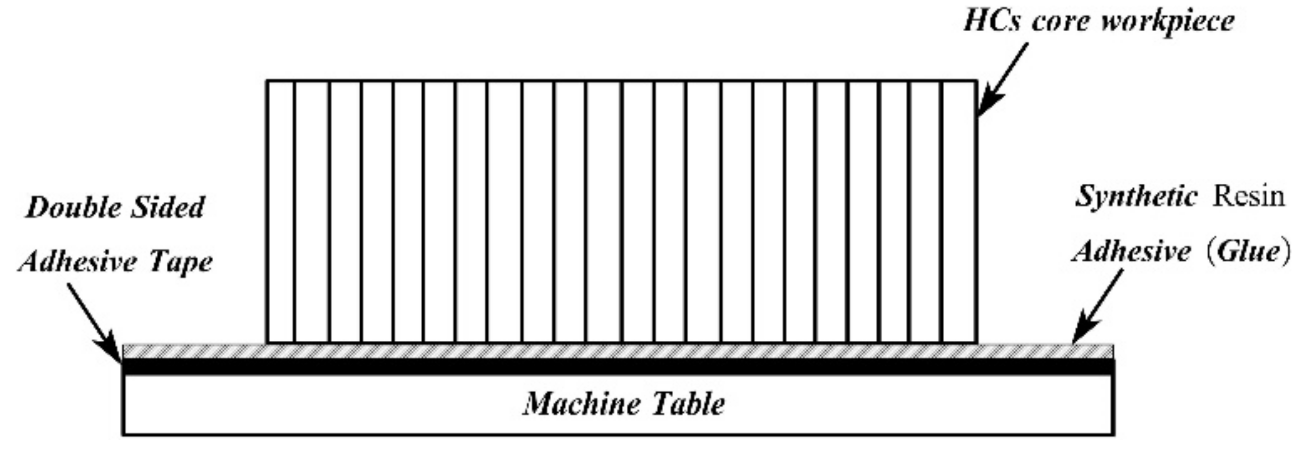
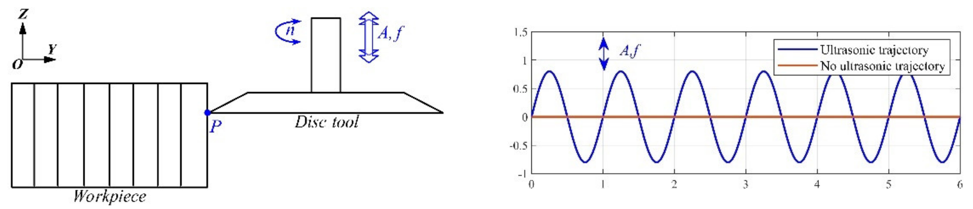
2. Experimental Synopsis

Most RUM systems are mainly composed of the following parts: ultrasonic power supply, ultrasonic converters, amplitude modifier (booster) and ultrasonic cutting tool. Ultrasonic power supply (ultrasonic generator) outputs high-frequency AC oscillating electrical signals. The ultrasonic transducer converts the high-frequency AC oscillating electrical signal output by the ultrasonic generator into a mechanical vibration signal with the same frequency, the ultrasonic transducer used in this paper is a piezoelectric ceramic sensor. The ultrasonic horn amplifies the amplitude of the weak mechanical vibration signal from the ultrasonic transducer to achieve the amplitude required for the actual cutting process, and at the same time, it can ensure that the entire acoustic system is always in a resonance state. The ultrasonic circular knife was used for processing the HC core. A schematic diagram of the RUM system for HC core workpiece machining was displayed in Figure 1.
In this paper, the experimental devices for RUM of Aluminum honeycomb composites (ALHCs) core workpiece and Nomex honeycomb composites (NHCs) core workpiece were illustrated in Figure 2 and Figure 3, respectively. Surface quality experiments for RUM of the HC core workpiece by UCK were executed on the ultrasonic machine tool (NO: IT5X111) produced by INNOTECH company. Ultrasonic equipment was installed on the machine tool, then ultrasonic cutting experiment was carried out by switching the power of the ultrasonic generator and air cooling was adopted for the cooling system in the machine tool, as shown in Figure 1, Figure 2 and Figure 3. Ultrasonic generator (Model: GT2010-GT2015), ultrasonic converters, amplitude modifier and ultrasonic cutting tool were developed by SONIMAT (EUROPE TECHNOLOGIES) in France. The major parameters of the RUM system are ultrasonic frequency (20 KHz), ultrasonic power (Max 1500 w), power supply:230 V mono 50/60 Hz, ultrasonic spline speed (Max 1000 rpm) and vibration amplitude (Max 0.08 mm). 63   mm disc cutting tool was used in the experiment, as shown in Figure 4.

3. Experiment Program

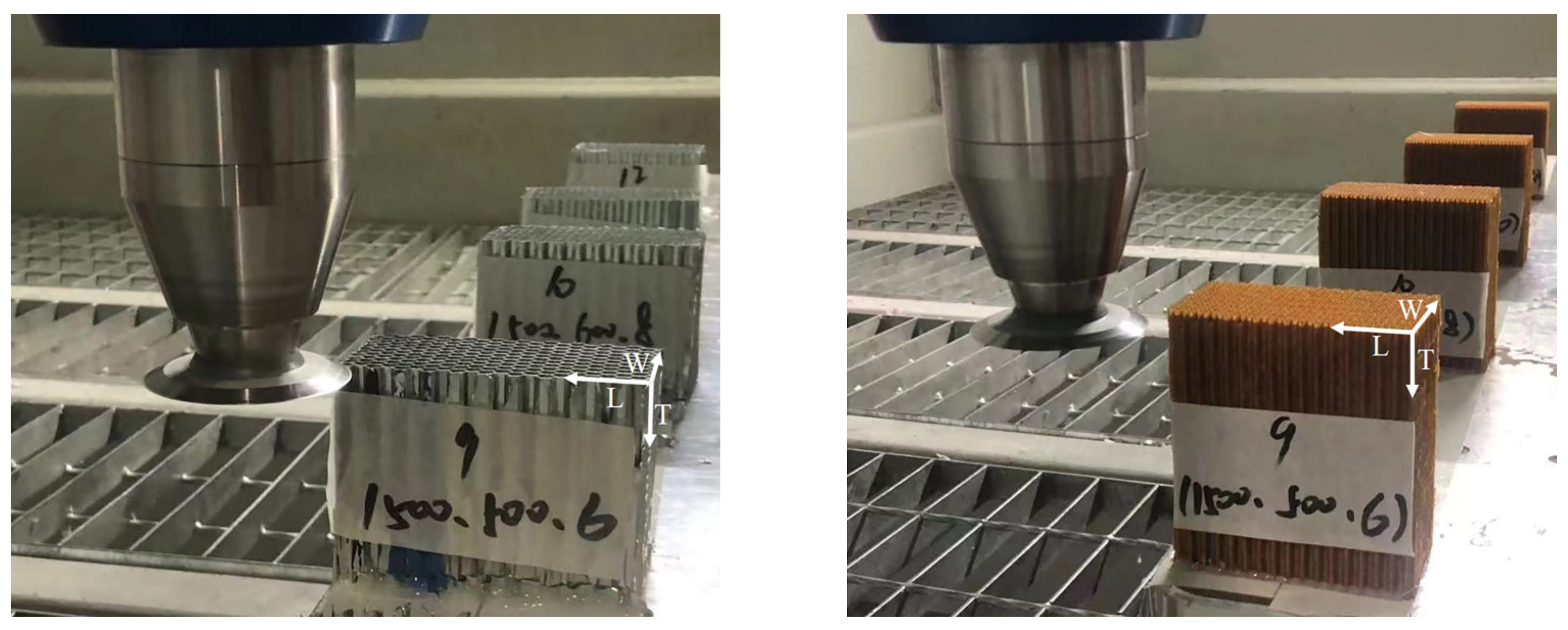
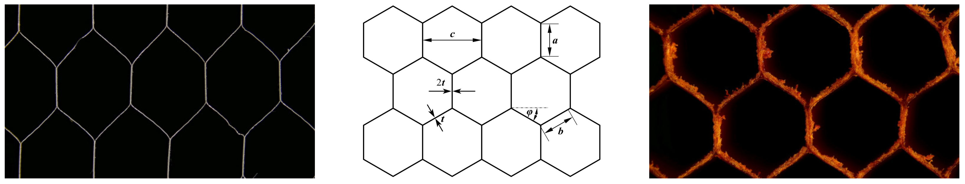
3.1. Materials Used in Experiment

In this experiment, the Nomex honeycomb composite core workpiece (Type Designation: ACCH-2I-1/8-3.0) was produced by AVIC Composite Materials Co., Ltd. The aluminum honeycomb composite core workpiece (Type Designation: HexWeb® CR-PAA-5052-3/16-3.1-Non-p) was produced by HEXCEL company. NHCs core workpieces with dimensions of ribbon (L), a direction perpendicular to the ribbon (W) and cell depth (T) as 100   mm × 50   mm × 100   mm and ALHCs core workpieces with dimensions of ribbon (L), a direction perpendicular to the ribbon (W) and cell depth (T) as 100   mm × 50   mm × 80   mm were used in this experiment, as shown in Figure 5. Key parameters for the hexagonal cellular structure of the workpiece are cell size, single wall thickness, double wall thickness and cell edges, as shown in Figure 5 and specimen attributes of ALHCs core workpiece and NHCs core workpiece were demonstrated in Table 1 and Table 2, respectively.
Double-sided adhesive tape and synthetic resin adhesive were used to fix ALHCs core and NHCs core workpiece (a group of four workpieces) on the machining table of the machine tool instead of fixing them on a special fixture due to the small dimensions of the workpiece. The fixing system of the specimen is shown in Figure 6.

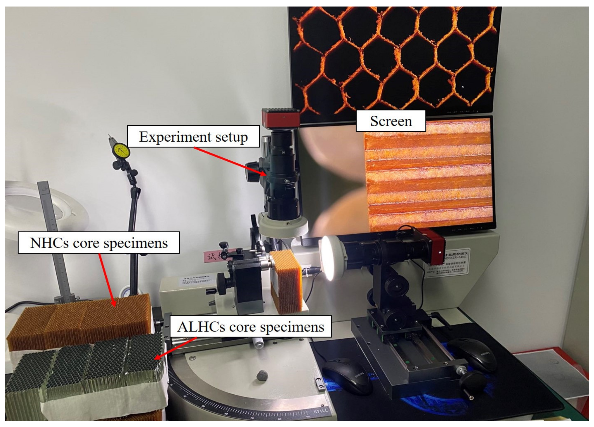
3.2. Measurement Methods for Surface Characteristics

To observe the machining results, a high-definition video detector (CHECKER145Linear-M, STILL, Guangdong China) was used to measure the surface morphology of ALHCs core and NHCs core workpieces after RUM, then, to observe processing defects of the workpiece under different cutting parameters and the effect on surface quality. The concrete analysis is reflected in Section 4. Experimental setup for surface morphology of ALHCs core and NHCs core workpieces are displayed in Figure 7.

3.3. Processing Conditions in the Experiment

High quality has always been the core goal of processing. Compared with traditional technology, rotary ultrasonic machining reduces surface defects and improves efficiency. Therefore, the reasonable selection of processing parameters has become the core issue to improve efficiency and workpiece surface quality. Thus, in this research, a group of single-factor experiments and orthogonal experiments with two-factors/four-levels and one-factor/three-levels were used to discuss the effect of cutting parameters such as cutting tool feed rate, tool cutting depth and ultrasonic spindle speed on surface quality. In experiments for ALHC core workpieces, the cutting depth remained at 0.8   mm for each experiment due to material property and great cutting effects. In the experiments for NHC core workpieces, cutting depth remained at 2   mm for each experiment. Vibration amplitude was kept fixed at 0.08   mm according to the manufacturer. According to the parameters of the ultrasonic equipment itself and the performance parameters of the machine tool with ultrasonic equipment, the single-factor experiments designed are illustrated in Table 3.
Through single-factor controlled variable method experiments, the effect of each parameter on the surface quality can be obtained. However, the interaction between different machining parameters cannot be illustrated in single-factor controlled variable method experiments. Therefore, two-factors/four-levels and one-factor/three-levels orthogonal experimental methods were designed to discuss the influence of distinct processing variables in this paper. Meanwhile, orthogonal experimental technology was used to obtain the optimal association of cutting parameters for rotatory ultrasonic machining of ALHC core workpieces and Nomex honeycomb core workpieces with a UCK cutting tool according to the orthogonal experiments. The parameter factors and levels in the orthogonal experiments of the RUM are displayed in Table 4. The two-factors/four-levels and one-factor/three-levels L 12 3 × 4 2 orthogonal experimental conditions of ALHC core and NHC core specimens are shown in Table 5.

4. Results and Discussion

The honeycomb sandwich structure consists of a high-strength adhesive bonding a relatively thin skin panel to a comparatively thick lightweight honeycomb core, and the overall structure is like a honeycomb structure. As the key component of a sandwich structure, a honeycomb core can greatly increase stiffness and strength on the premise of slightly increasing the overall quality of the sandwich structure, and is lightweight. Therefore, processing quality directly affects the performance and service life. RUM technology is used in composite material machining to greatly reduce defects and improve surface quality. Therefore, it is worthwhile to further study the processing characteristics of RUM with UCK and the influence of different cutting parameters on the workpiece surface quality. However, the ultrasonic cutting tool used in this experiment was newly fabricated, so tool tear was ignored and dust, delamination and collapse of cells did not exist in this study due to the RUM technology. In these experiments, the processing principle of the RUM technology and the disc cutting tool ultrasonic vibration trajectory are displayed in Figure 8. In this figure, A represents ultrasonic amplitude, f represents ultrasonic frequency, n represents disc tool rotary velocity and P represents any point on the disc cutting tool. When the disc cutting tool is without ultrasonic vibration, the tangential velocity V t was much greater than feed velocity V f , therefore, tool rotational motion was the main motion, and V t can be expressed as:
V t = π D n
where D represents disc cutting tool diameter.
When the disc cutting tool used ultrasonic vibration, the cutting tool produced displacement S with periodic changes in magnitude and direction along the tool axis. S can be expressed as:
S = A · sin 2 π f t + θ
where t represents the cutting time, θ represents the vibration initial phase angle. Differently to Equation 2, vibration cutting velocity along the tool axis ( Z direction) can be obtained as:
V s = 2 π f A · cos 2 π f t
In the RUM technology, the vibration cutting velocity V s was much greater than the tangential velocity V t   and feed velocity V f , therefore, tool vibration motion along the tool axis became the main motion in processing. The magnitude and the direction of V s changed periodically over time.
Then, the authors observed the effect of different processing parameters on the workpiece surface with a disc ultrasonic cutting tool. The surface morphology of the ALHC core and the NHC core workpieces under different processing parameters was analyzed in detail below.

4.1. ALHC Core Surface Quality Analysis

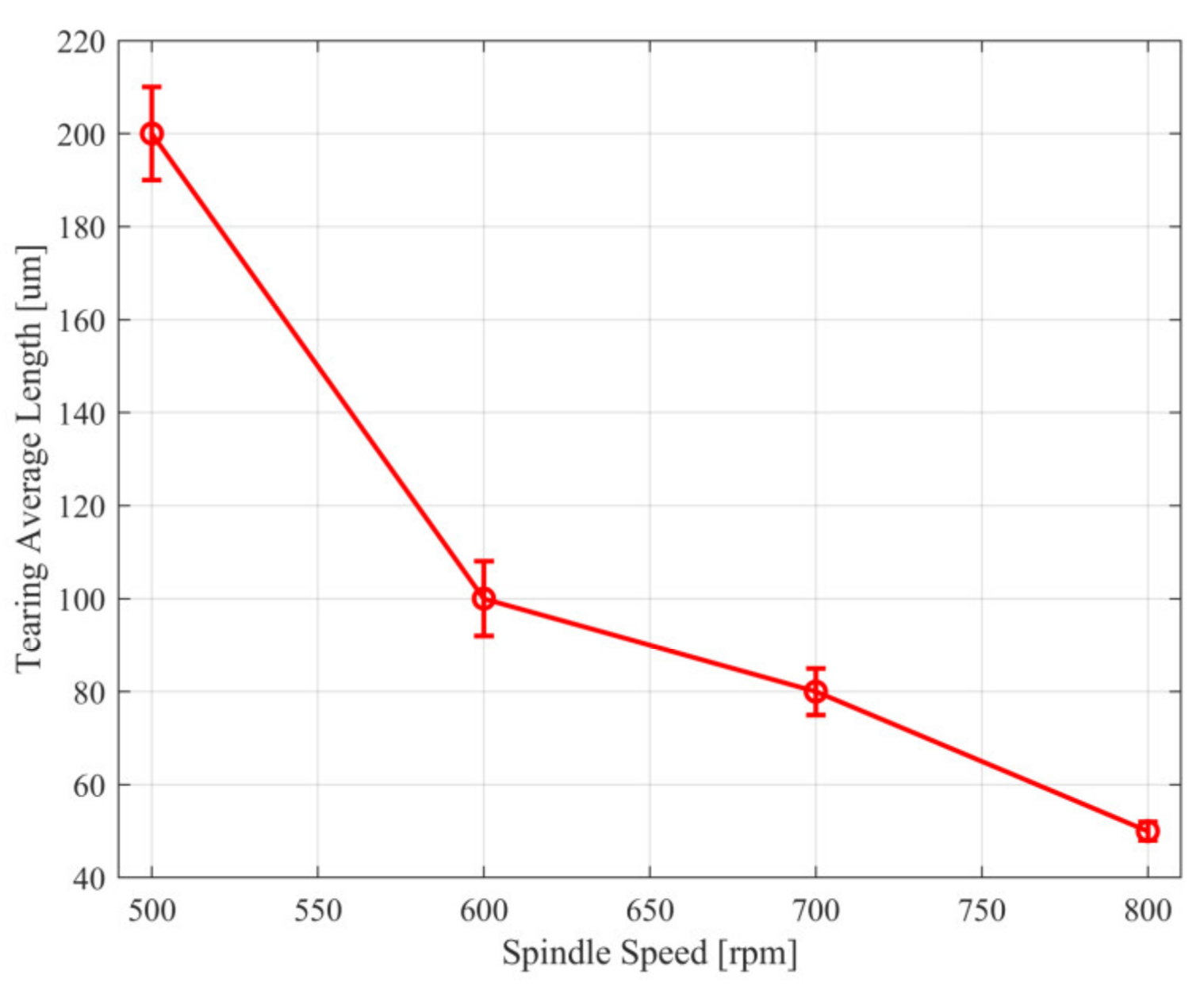
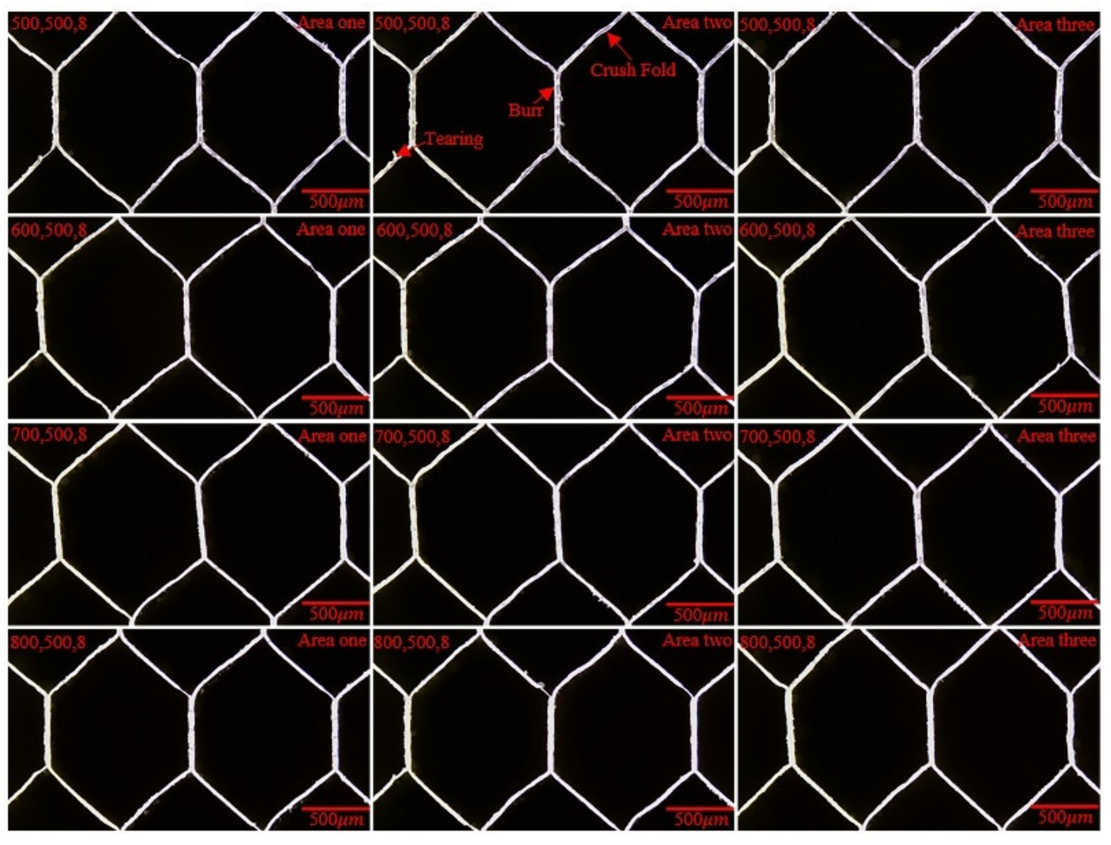
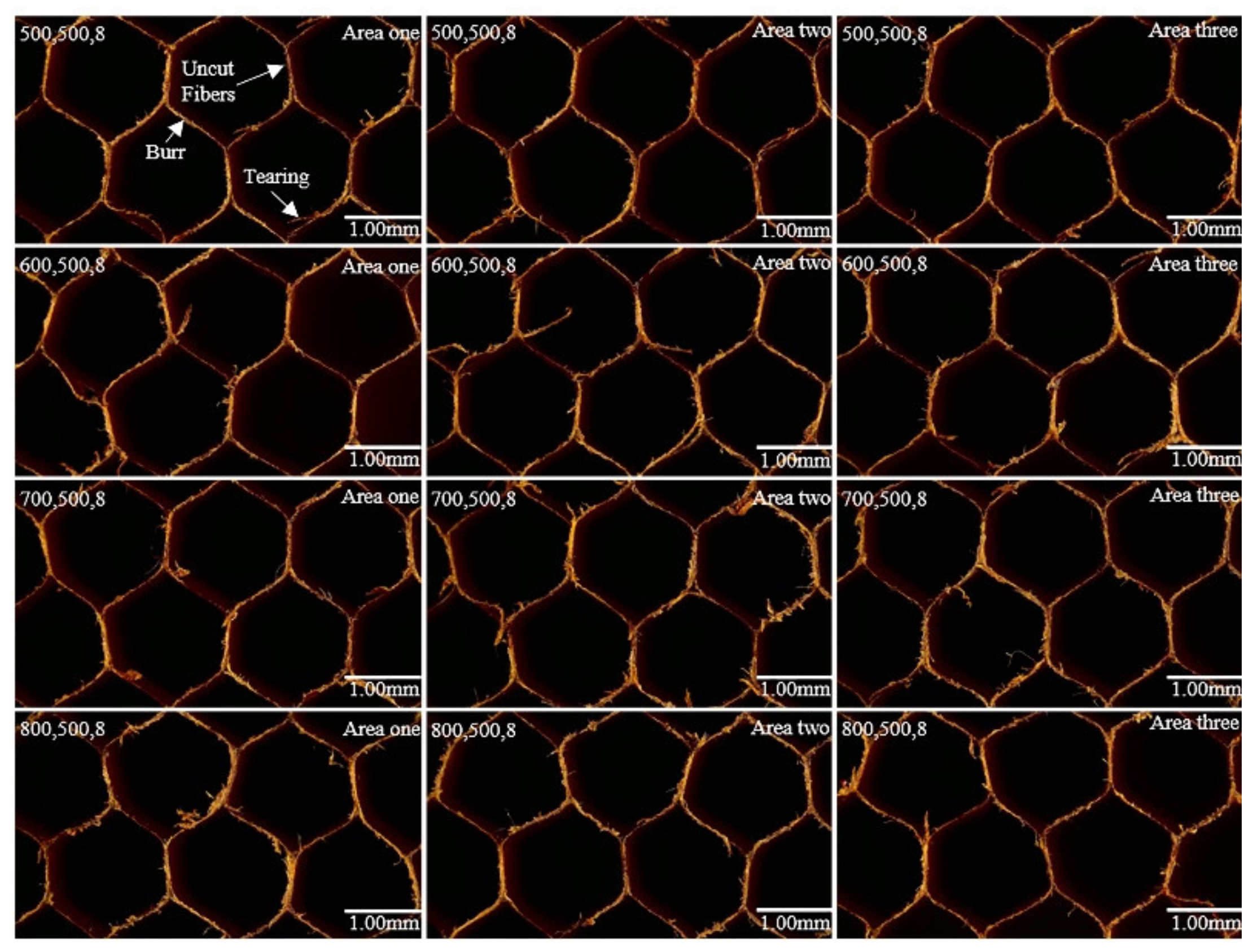
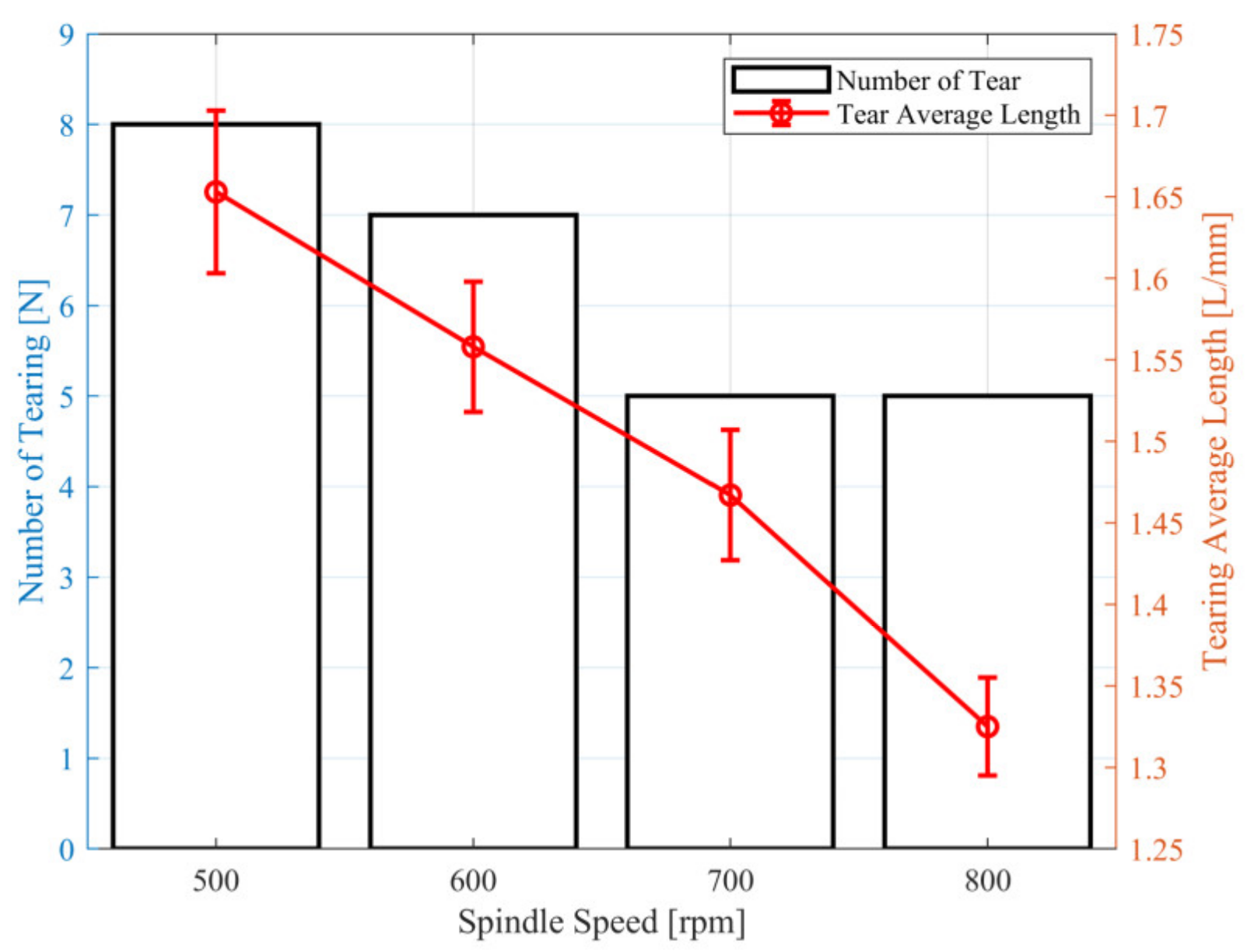
4.1.1. Results of Ultrasonic Spindle Speed on Surface Morphology

The effect degree of the ultrasonic spindle speed on the workpiece surface morphology was studied by rotatory ultrasonic machining tests on the ALHC core workpiece with a UCK cutting tool on the machine tool. The parameters of the cutting tool feed rate, tool cutting width, and tool cutting depth were fixed, and the spindle speed was gradually increased. The average length of tears L was used as the evaluation parameter to measure the surface quality due to tears that seriously affected the service life of the part. The processed surface was divided into three equal observation areas, two honeycomb cells can be observed in each observation area. The average tearing length was measured by the experiment setup in Figure 7, as shown in Figure 9. The surface quality experimental results of the RUM with the UCK cutting tool are shown in Figure 10.
As shown in Figure 9 and Figure 10, the feed rate is fixed at 500   mm / min , the cutting width is fixed at 8   mm and the cutting depth is fixed at 0.8   mm . The range of spindle speeds is 500~800 rpm. The defect mainly included tearing, burr and crush fold on the surface morphology with the machined workpiece. The amount and the average length of tearing decreased with increased spindle speed during the ultrasonic machining experiment of the ALHC core workpieces with an ultrasonic circular knife cutting tool. The shearing effect on the material increased with an increased spindle speed, therefore, the shearing length decreased in this experiment at different spindle speeds from 500~800 rpm. Burr changed the same as tearing.

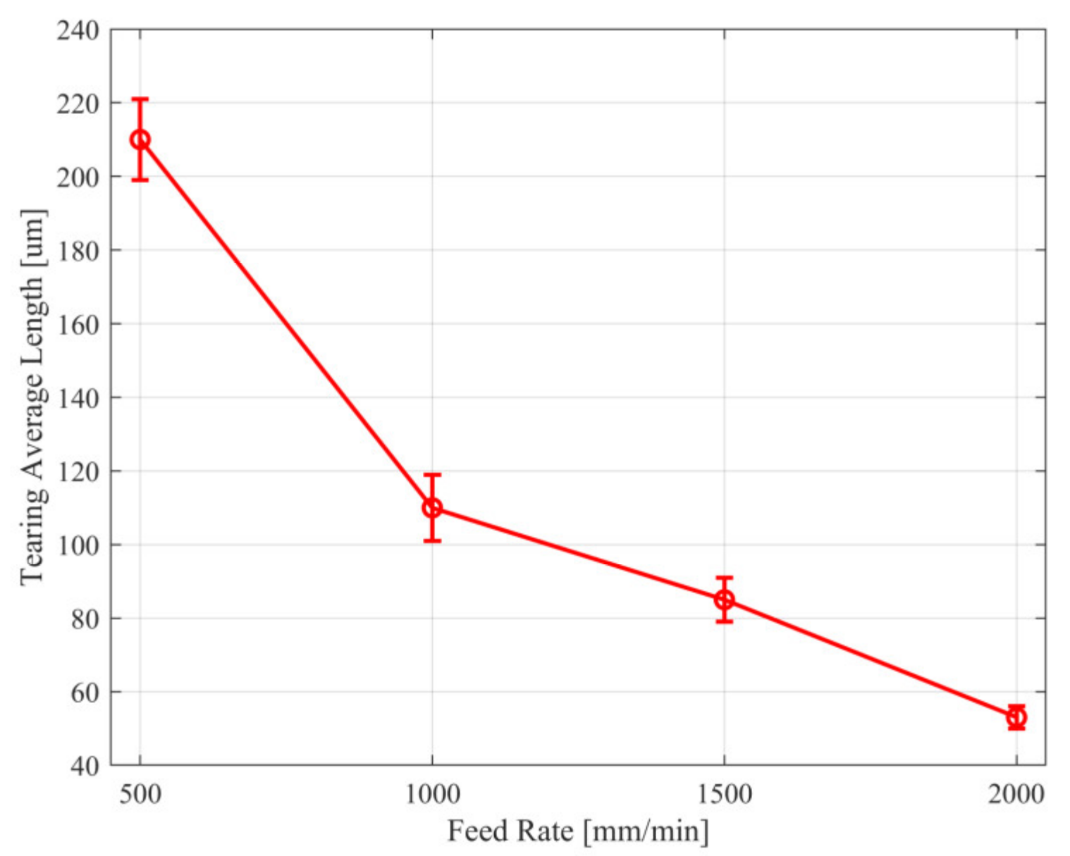
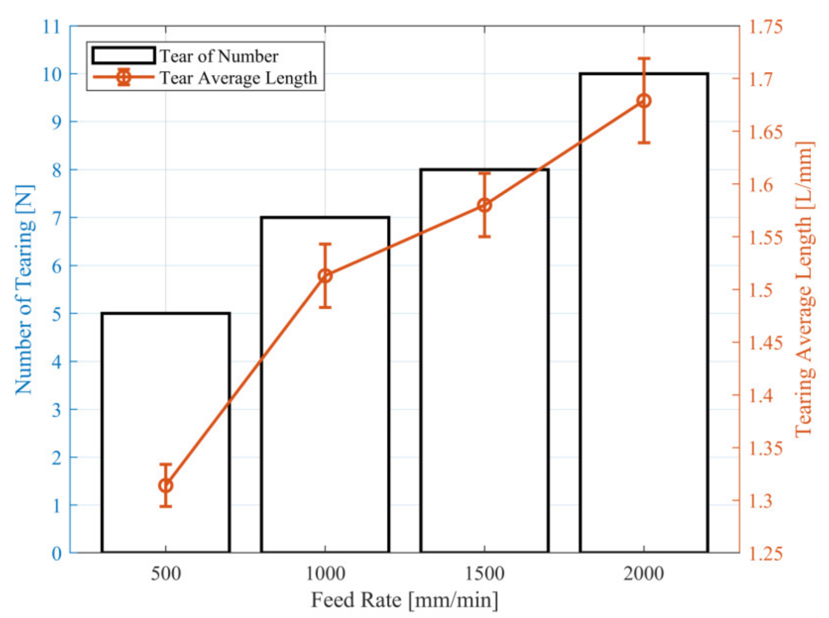
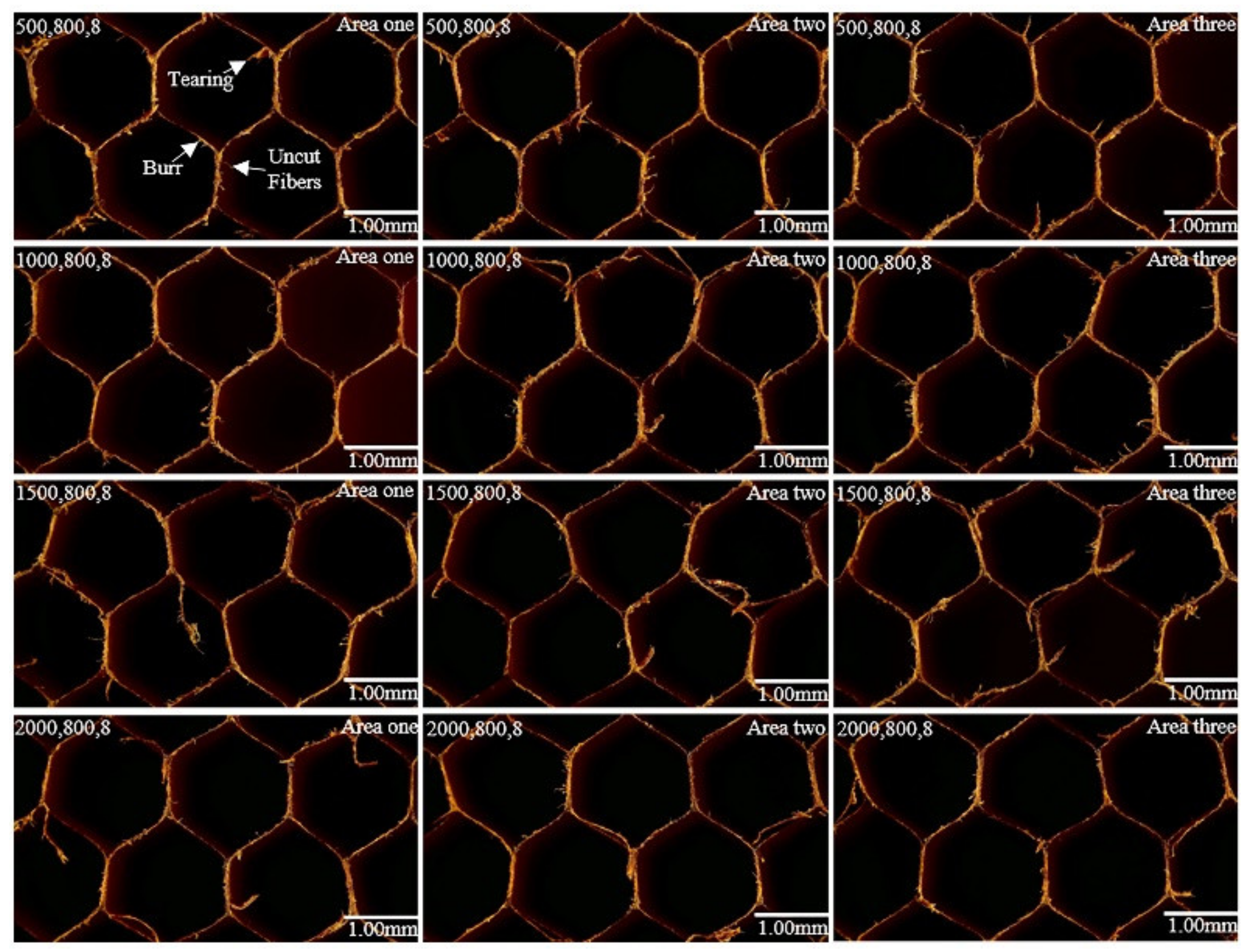
4.1.2. Results of Tool Feed Rate on Surface Morphology

The effect of the degree of tool feed rate on surface morphology was studied by rotatory ultrasonic machining tests on the ALHC core workpiece with a UCK cutting tool on the machine tool. The parameters of spindle speed, cutting width, and cutting depth were fixed, and the feed rate was gradually increased. The average tearing length was measured with the experimental setup in Figure 7, as shown in Figure 11. The surface quality experimental results of the RUM with a UCK cutting tool are shown in Figure 12.
As shown in Figure 11 and Figure 12, spindle speed is fixed at 800   rpm and cutting width is fixed at 8   mm . Both the number and length of tears decreased as the feed rate increased. The reason for this phenomenon was due to the increased feed rate speeding up the cutting process, shortening the touching time between the tool and the workpiece, thus improving the surface morphology to a certain extent, although the cutting force in the processing increased with an increased cutting tool feed rate.

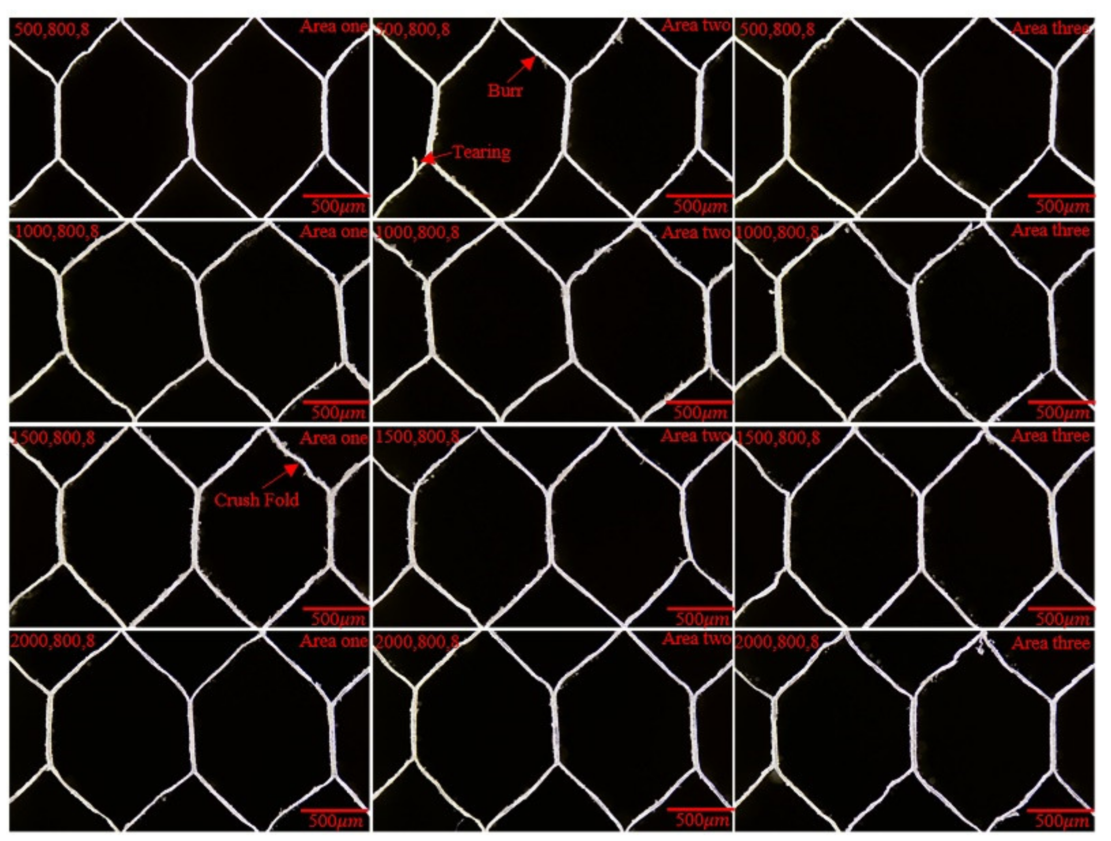
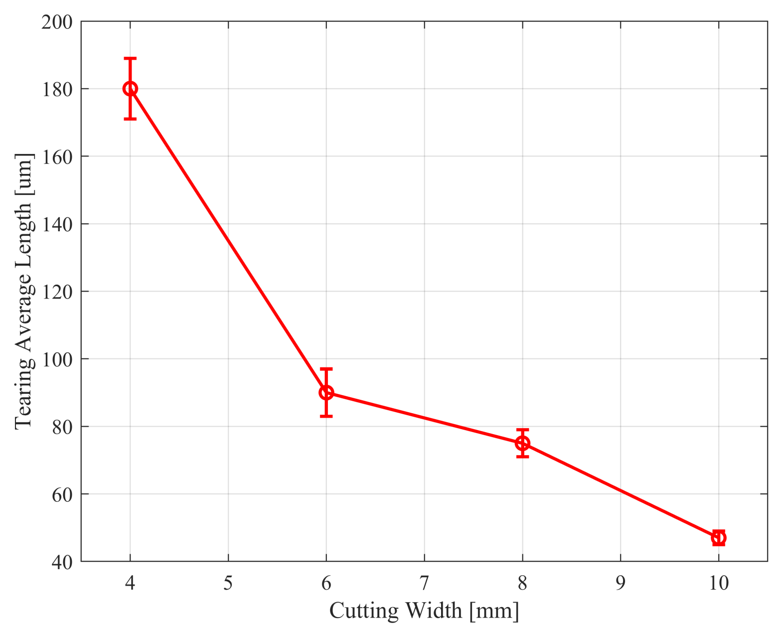
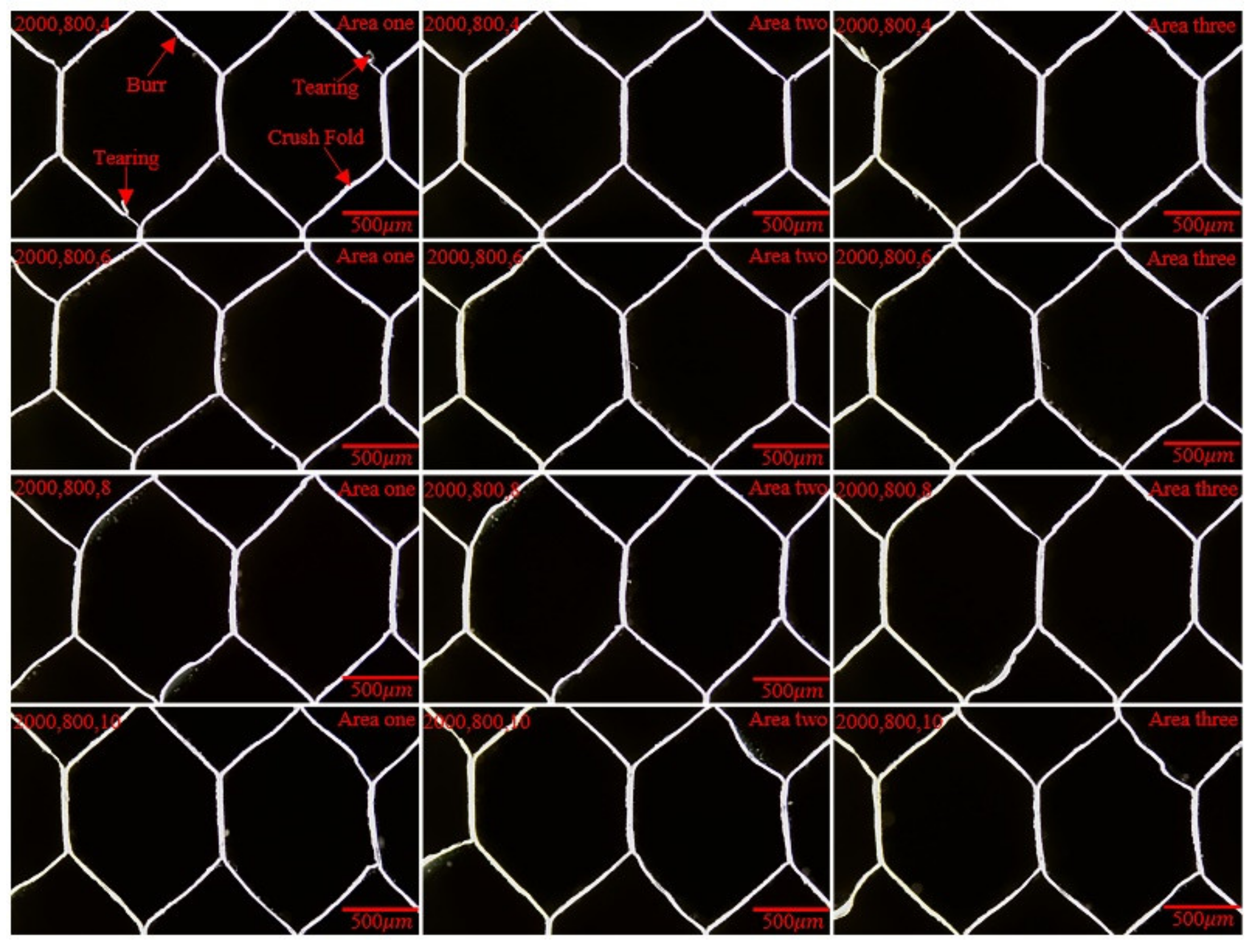
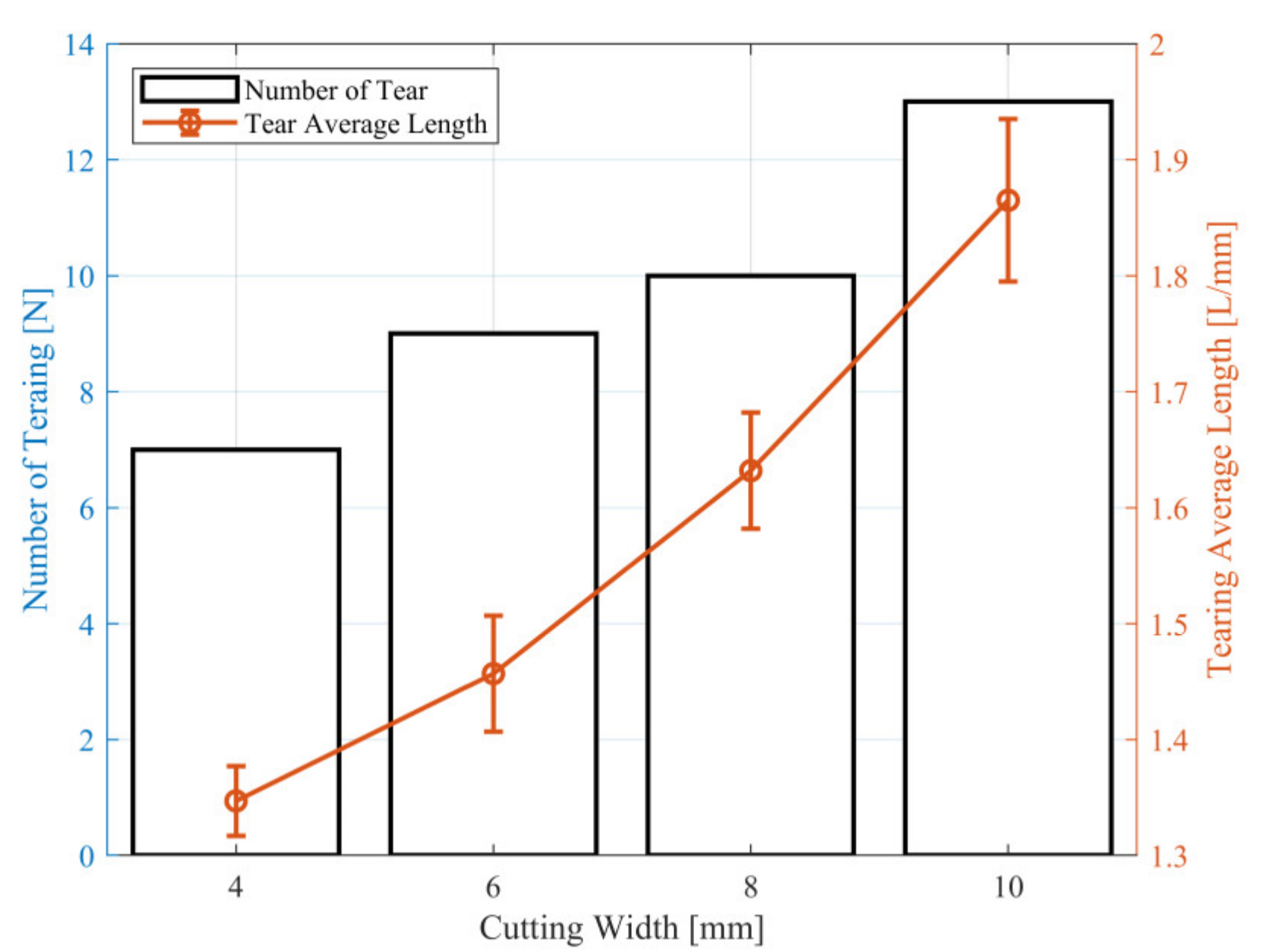
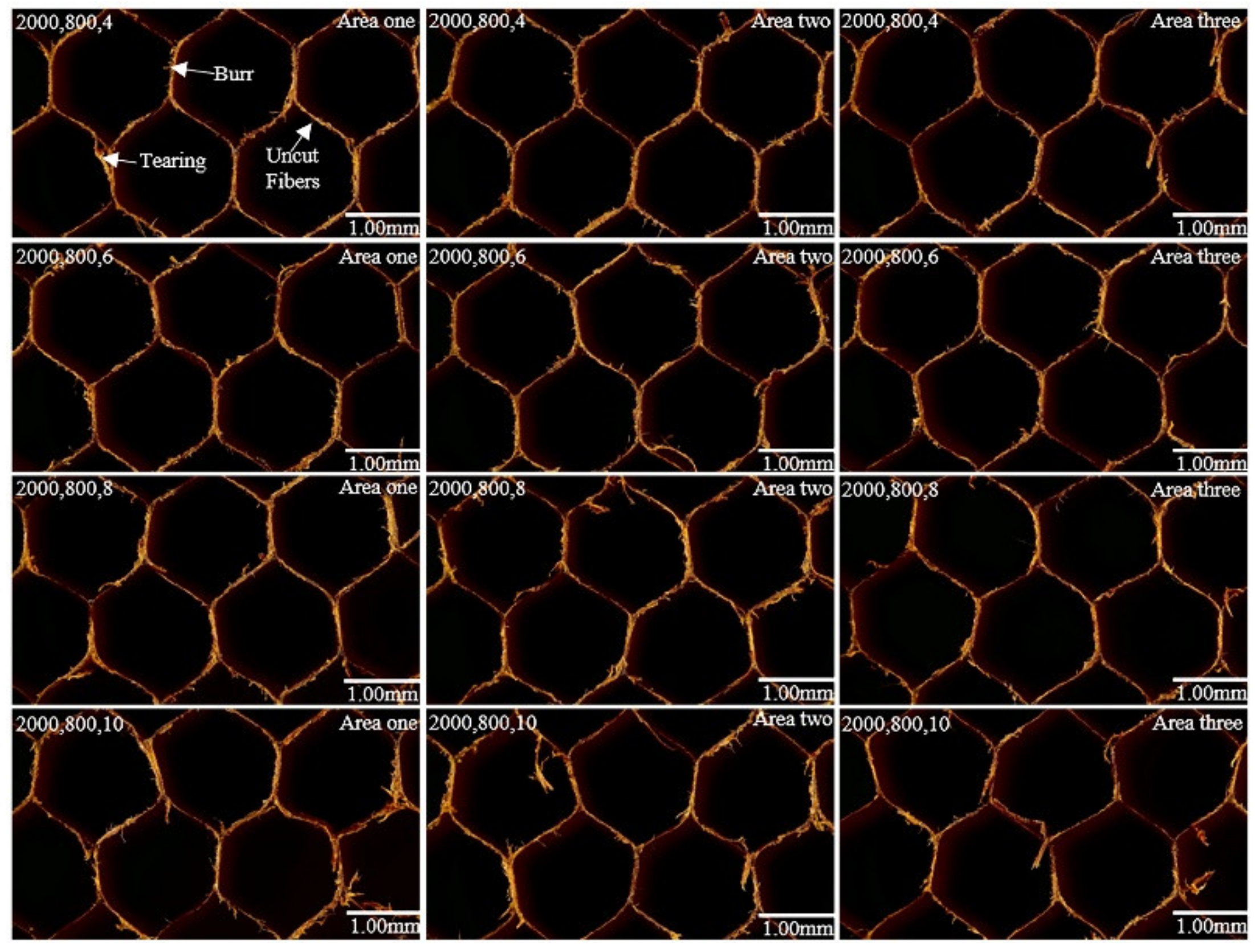
4.1.3. Result of Tool Cutting Width on Surface Morphology

The effect of the degree of cutting width on surface morphology was researched by rotatory ultrasonic machining experiments on the ALHC core workpiece with a UCK cutting tool on the machine tool at different cutting widths from 4   μ m to 10   μ m . The parameters of the ultrasonic spindle speed, tool feed rate, tool cutting depth were fixed. The average tearing length was measured by the experimental setup in Figure 7, as shown in Figure 13. The surface quality experimental results of the RUM with a UCK cutting tool are shown in Figure 14.
As shown in Figure 13 and Figure 14, the feed rate was fixed at 2000   mm / min and the spindle speed was fixed at 800   rpm . During the RUM experiments of the NCH core workpieces, tearing length decreased to a certain extent with an increased tool cutting width, but the effect was small. The authors found that the crush fold phenomenon was largely affected by the cutting width. The stiffness of the cell single wall was lower, therefore, the AL honeycomb cell single wall underwent plastic deformation due to the cutting force. The increase in tool cutting width increased the touching area between the cutting tool and the aluminum honeycomb, therefore, the material volume increased in the cutting process. The larger the cutting width, the more prone the aluminum honeycomb wall was to plastic deformation, which can lead to a crush fold defect.

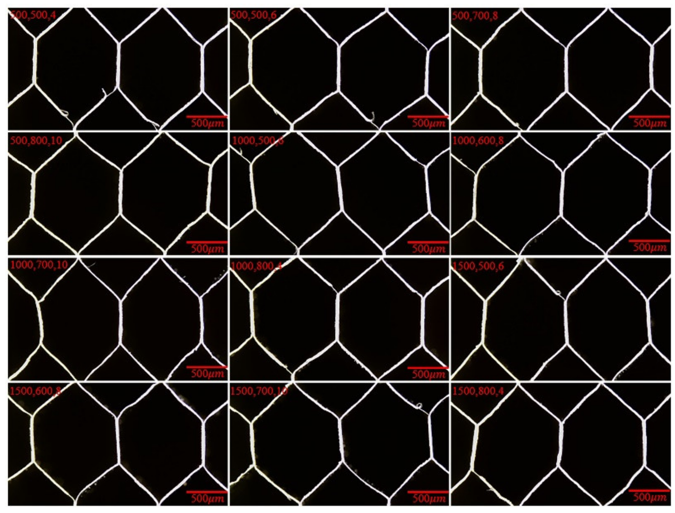
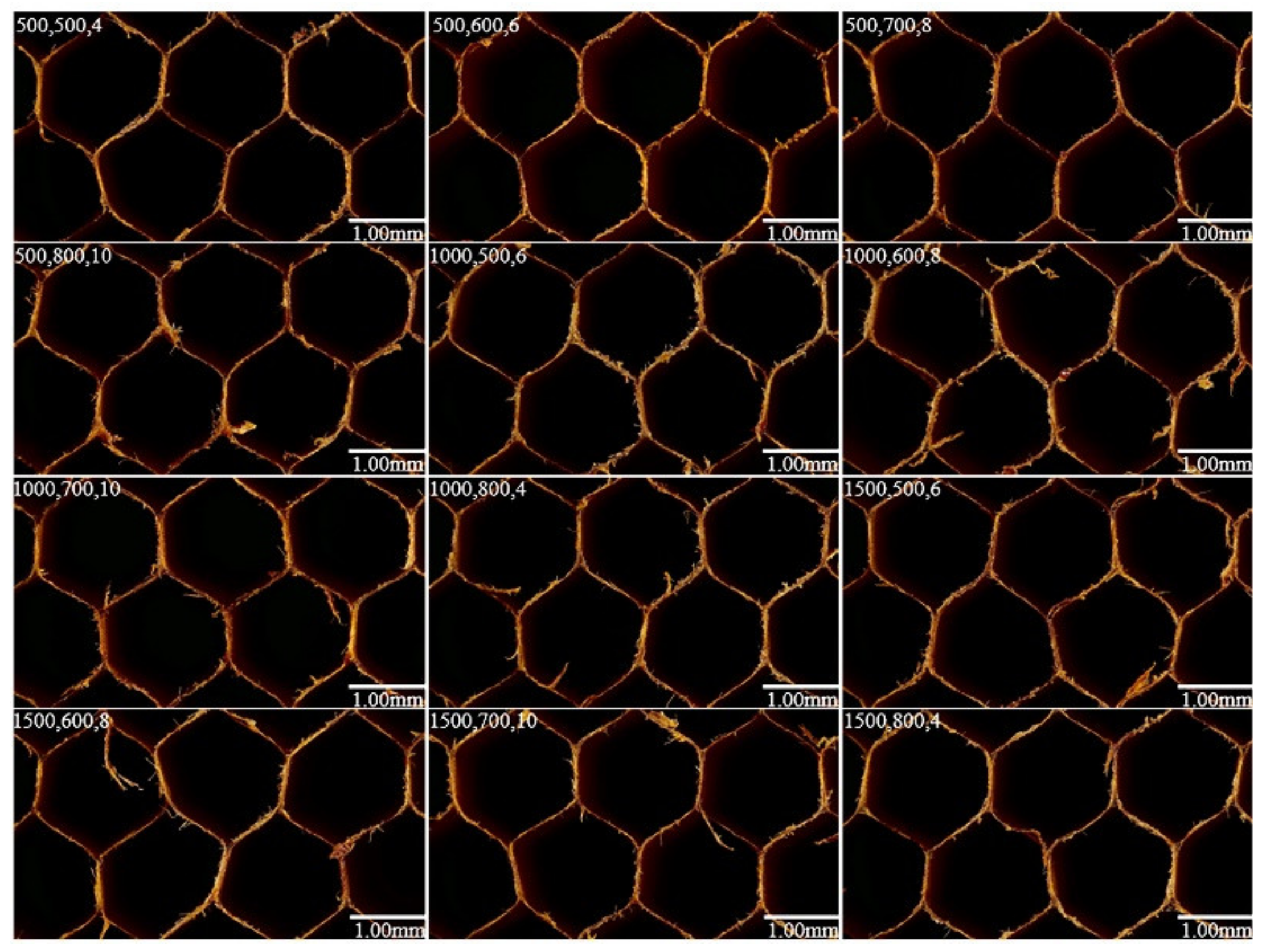
4.1.4. Results of Cutting Parameters on Surface Morphology by Two-Factors/Four-Levels and One-Factor/Three-Factors L 12 3 × 4 2 Orthogonal Experiments

The influence of a single variable on the surface morphology of the ALHC core workpiece can be obtained through a group of single-factor experiments. However, the effect of a different combination of multiple variables on surface morphology cannot be determined. Therefore, according to the performance of the machine tool and ultrasonic device, two-factors/four-levels and one-factor/three-factors orthogonal experiments technology was proposed to study the effect of different cutting parameters on surface morphology. In this paper, the influence of various parameters, namely ultrasonic spindle speed, cutting tool feed rate and cutting width under the constant value of vibration amplitude 0.08   mm and cutting depth 2   mm were obtained by rotatory ultrasonic machining on an ALHC core specimen with an ultrasonic circular knife cutting tool. The authors only showed surface experimental results in area one to save space, as shown in Figure 15. In order to further analyze the significance of machining variables, the results of the orthogonal experiments were quantified by the evaluation parameter, namely L , of surface macro-topography proposed above. The orthogonal experimental significance analysis results in the average length L of tearing, as shown in Table 6.
In conclusion from Table 6, the range variance of tearing average L among the three processing variables including ultrasonic spindle speed, tool feed rate and tool cutting width under the constant cutting depth and ultrasonic vibration amplitude during ultrasonic machining experiments of the Nomex honeycomb core workpiece by disc was:
R f e e d   r a t e > R s p i n d l e   s p e e d > R c u t t i n g   w i d t h
It can be seen from Equation (1) that feed rate has the maximum effect on the tearing average length L and the cutting width has the minimum influence on the tearing average L .

4.2. NHC Core Surface Quality Analysis

4.2.1. Results of Ultrasonic Spindle Speed on Surface Morphology

The influence of the degree of ultrasonic spindle speed on surface quality was studied by rotatory ultrasonic machining experiments on a Nomex HC core workpiece with a disc cutting tool on the machine tool. The parameters of tool feed rate, tool cutting width, and cutting depth were fixed, and the spindle speed was gradually increased. The number of tears N (length more than 1   mm ) and the average length of tears L were used as evaluation parameters to measure the surface quality as a surface with tears will seriously affect the service life of the part. The processed surface was divided into three equal observation areas, five honeycomb cells can be observed in each observation area, and the total number of tears and the average length of the three observation areas are counted. The surface quality experimental results of the RUM with a UCK cutting tool are shown in Figure 16. The average tearing length and amount were measured by the experimental setup in Figure 7, as shown in Figure 17.
As shown in Figure 16 and Figure 17, area one, area two, and area three represent the observation areas, respectively. The feed rate was fixed at 500   mm / min , the cutting depth was fixed at 2   mm and the cutting width was fixed at 8   mm . The average length of tears L decreased when increasing the ultrasonic spindle speed and the total number of tears changes less during the experiments on the Nomex HC core specimen with a disc cutting tool.
The reason for this conclusion is that the high-frequency vibration of the cutting tool makes the vibration speed far greater than the tangential speed of the disc cutter during RUM, and the main cutting motion is the ultrasonic vibration of the tool. The main force for fracture separation of the honeycomb wall is not the shear force, but the high-frequency impact force of the disc cutter on the chip and the machined surface. Therefore, the change of spindle speed has little effect on the extrusion and the friction force of the cutting tool on the material along the feeding direction, and the amount of tearing does not change significantly. However, the increase in spindle speed can increase the shearing effect on the material to a certain extent, therefore, the shearing length decreases with an increase in cutting tool speed. The cutting force in processing decreases with ultrasonic spindle speed which increases in rotatory ultrasonic machining experiments of the NHC core specimens, therefore, the number of burrs decreases.

4.2.2. Results of Tool Feed Rate on Surface Morphology

The effect of the degree of tool feed rate on surface quality was studied with rotatory ultrasonic machining experiments on a Nomex HCs core workpiece with a disc cutting tool on the machine tool. The parameters of spindle speed, cutting width, and cutting depth were fixed, and the feed rate was gradually increased. The average tearing length and amount of tears were measured by the experimental setup in Figure 7, as shown in Figure 18. The surface quality experimental results of the RUM by disc cutting tool are displayed in Figure 19.
As shown in Figure 18 and Figure 19, the spindle speed is fixed at 800   rpm and the cutting width is fixed at 8   mm . Both the number and length of tears increase as the feed rate increases. In ultrasonic cutting, the extrusion force of the cutting tool on the material decreases with a feed rate decrease. Therefore, the tearing defect generated by the cutting tool due to the compressive deformation of the honeycomb core wall increases when increasing the tool feed rate. However, RUM technology has a greater effect on reducing the extrusion force, therefore, the effect of feed rate on tearing tends to be gentle.

4.2.3. Results of Tool Cutting Width on Surface Morphology

The effect of the degree of tool cutting width on surface quality was studied by rotatory ultrasonic machining tests on a Nomex HC core workpiece with a disc cutting tool on the machine tool at different cutting widths from 4   μ m to 10   μ m . The parameters of the ultrasonic spindle speed, tool feed rate, and cutting depth were fixed. The average tearing length and amount of tears were measured by the experimental setup in Figure 7, as shown in Figure 20. The surface quality experimental results of RUM with the disc cutting tool are illustrated in Figure 21.
As shown in Figure 20 and Figure 21, the feed rate was fixed at 2000   mm / min and the spindle speed was fixed at 800   rpm .
Both the number and length of tears increase as the cutting width increases with the disc cutting tool during the RUM tests of the NCH core workpieces. The reason for this conclusion is that the touching area between the disc tool and the workpiece corresponding to the different cutting widths was also different, and the contact area was proportional to the cutting width, resulting in the larger the cutting width, the greater the friction between the tool and the workpiece in the cutting process. Burr changed the same as tearing.

4.2.4. Results of Cutting Parameters on Surface by Two-Factors/Four-Levels and One-Factor/Three-Factors L 12 3 × 4 2 Orthogonal Experiments

The influence degree of a single variable on the surface morphology of the Nomex HC core workpiece can be obtained through a group of single-factor experiments. However, the influence of a different combination of multiple variables on surface morphology cannot be determined. Therefore, according to the performance of the machine tool and the ultrasonic device, two-factors/four-levels and one-factor/three-factors orthogonal experiments technology were proposed to study the effect of different cutting parameters on surface morphology. In this study, the effect of cutting parameters on surface quality was investigated by establishing orthogonal experiments with different variable combinations. The authors only showed surface experiments in the results area one to save space, as shown in Figure 22. To further discuss the significance of cutting parameters, the results of orthogonal experiments were quantified by evaluation parameters, namely N ,   L , of the surface macro-topography, as proposed above. The orthogonal experimental significance analysis results of the total amount N and average length L of tearing were measured by the experimental device in Figure 7, as shown in Table 7 and Table 8 separately.
In conclusion from Table 7, the range in the variance of tearing amount N among the three processing variables including ultrasonic spindle speed, tool feed rate and tool cutting width under the same depth and ultrasonic vibration amplitude of ultrasonic machining for the Nomex HC core workpiece with a disc cutting tool was:
R c u t t i n g   w i d t h > R f e e d   r a t e > R s p i n d l e   s p e e d
From Equation (2) it can be observed that the cutting width has the maximum effect on the tearing amount N and the spindle speed has the least influence on the tearing amount N .
In conclusion from Table 8, the range in the variance of average tearing length L among the three processing variables including ultrasonic spindle speed, tool feed rate and tool cutting width under an identical depth and ultrasonic vibration amplitude of ultrasonic machining for the Nomex HC core workpiece with a disc cutting tool was:
R c u t t i n g   w i d t h > R s p i n d l e   s p e e d > R f e e d   r a t e
From Equation (3) it can be seen that the cutting width has the maximum effect on the average tearing length L and the feed rate has the least influence on the tearing average L .

5. Conclusions

In this paper, the surface quality experiment for rotatory ultrasonic machining (RUM) of a honeycomb composite core (aluminum honeycomb and Nomex honeycomb) by ultrasonic circular knife (UCK) was developed to research the influence of different cutting variables on surface morphology for the aluminum honeycomb composite (ALHCs) core workpiece and the Nomex honeycomb composite (NHCs) core workpiece through a serious of single-factor experiments. Then, the optimal processing parameters of ultrasonic machining were received through orthogonal experimental technology. The results can be concluded as follows.
For the ALHC core workpiece, processing defects mainly include burr, tearing and crush fold of RUM with an ultrasonic disc cutting tool. Burr and tearing decrease with increasing ultrasonic spindle speeds and disc tool feed rates due to the increase in spindle speed increasing the shearing effect on the material to a certain extent and the increasing disc tool feed rate can speed up the cutting process, shortening the touching time between the disc cutting tool and the workpiece. Crush folds were largely affected by the cutting width through a group of single-factor experiments and these defects increase with the increase in cutting width due to the aluminum honeycomb being more prone to plastic deformation when there is a larger contact area between the cutting tool and the aluminum honeycomb. Feed rate has the greatest effect on the tearing average of surface morphology and cutting width has the smallest influence during the RUM experiment with a UCK cutting tool through significance analysis of two-factors/four-levels and one-factor/three-levels ( L 12 3 × 4 2 ) orthogonal experimental results.
For the NHC core workpiece, burr, tearing and uncut fiber defects existed on the surface morphology of the RUM with a UCK cutting tool. Burr and tearing decrease when improving the ultrasonic spindle speed owing to the high-frequency impact force of the disc cutter on the chip and the machined surface. However, tearing increases with the improvement in disc tool feed rate because of an increase in extrusion force of the cutting tool on the material and the increase in material removal volume by the single-factor experiments. Therefore, burr and tearing increase when increasing the disc tool cutting width due to the increase in the touching area between the disc tool and the workpiece, resulting in an improvement in tool cutting force. Cutting width has the greatest effect on the tearing average and the number of tears to the surface morphology. Spindle speed has the smallest influence on the number of tears and the feed rate has the least effect on the tearing average during this experimental study by significance analysis of two-factors/four-levels and one-factor/three-levels ( L 12 3 × 4 2 ) orthogonal experimental results.
The research in this paper can provide a basis for the subsequent comprehensive consideration of various factors to achieve high-quality processing of HC and it should be noted that the conditions of all single-factor experiments and orthogonal experiments in this paper were designed according to the actual performance of ultrasonic CNC machine tools in a factory, therefore, the results of this paper are generally applicable to most factories involved in the high surface quality processing of honeycomb composites.

Author Contributions

G.L. contributed to the conceptualization. J.Y. contributed to the experiment, writing and editing. L.Z. contributed to the methodology. Q.G. and L.Q. provided resources and performed experiment verification. R.Z. contributed to the English in the manuscript. All authors have read and agreed to the published version of the manuscript.

Funding

The research is sponsored by the National Natural Science Foundation of China (No. 51775328).

Institutional Review Board Statement

Not applicable.

Informed Consent Statement

Not applicable.

Data Availability Statement

The datasets generated and analyzed during the current study are available from the corresponding author on reasonable request.

Acknowledgments

The authors would like to thank Sichuan Innov Aviation Technology Co., Ltd., China and Suzou Interroll CNC Technology Co., Ltd., China for supporting the experiment equipment.

Conflicts of Interest

The authors declare no conflict of interest.

References

  1. Harders, H.; Hupfer, K.; Rösler, J. Influence of cell wall shape and density on the mechanical behaviour of 2D foam structures. Acta Mater. 2005, 53, 1335–1345. [Google Scholar] [CrossRef]
  2. Habib, F.N.; Iovenitti, P.; Masood, S.H.; Nikzad, M. Cell geometry effect on in-plane energy absorption of periodic honeycomb structures. Int. J. Adv. Manuf. Technol. 2018, 94, 2369–2380. [Google Scholar] [CrossRef]
  3. Cvitkovich, M.K.; Jackson, W.C. Compressive Failure Mechanisms in Composite Sandwich Structures. J. Am. Helicopter Soc. 1999, 44, 260–268. [Google Scholar] [CrossRef]
  4. Zhou, G.; Hill, M.; Loughlan, J.; Hookham, N. Damage Characteristics of Composite Honeycomb Sandwich Panels in Bending under Quasi-static Loading. J. Sandw. Struct. Mater. 2006, 8, 55–90. [Google Scholar] [CrossRef]
  5. Kim, C.-G.; Jun, E.-J. Impact Resistance of Composite Laminated Sandwich Plates. J. Compos. Mater. 1992, 26, 2247–2261. [Google Scholar] [CrossRef]
  6. Abrate, S. Localized Impact on Sandwich Structures with Laminated Facings. Appl. Mech. Rev. 1997, 50, 69–82. [Google Scholar] [CrossRef]
  7. Lacy, T.E.; Hwang, Y. Numerical modeling of impact-damaged sandwich composites subjected to compres-sion-after-impact loading. Compos. Struct. 2003, 61, 115–128. [Google Scholar] [CrossRef]
  8. Aktay, L.; Johnson, A.F.; Kröplin, B.-H. Numerical modelling of honeycomb core crush behaviour. Eng. Fract. Mech. 2008, 75, 2616–2630. [Google Scholar] [CrossRef]
  9. Zhou, Z.; Wang, Z.; Zhao, L.; Shu, X. Experimental investigation on the yield behavior of Nomex honeycombs under combined shear-compression. Lat. Am. J. Solids Struct. 2012, 9, 515–530. [Google Scholar] [CrossRef] [Green Version]
  10. An, Q.; Dang, J.; Ming, W.; Qiu, K.; Chen, M. Experimental and Numerical Studies on Defect Characteristics During Milling of Aluminum Honeycomb Core. J. Manuf. Sci. Eng. 2019, 141, 031006. [Google Scholar] [CrossRef]
  11. Abbadi, A.; Tixier, C.; Gilgert, J.; Azari, Z. Experimental study on the fatigue behaviour of honeycomb sandwich panels with artificial defects. Compos. Struct. 2015, 120, 394–405. [Google Scholar] [CrossRef]
  12. Meruane, V.; del Fierro, V. An inverse parallel genetic algorithm for the identification of skin/core debonding in honeycomb aluminium panels. Struct. Control Health Monit. 2015, 22, 1426–1439. [Google Scholar] [CrossRef]
  13. Wang, J.; Feng, P.; Zhang, J.; Guo, P. Experimental study on vibration stability in rotary ultrasonic machining of ceramic matrix composites: Cutting force variation at hole entrance. Ceram. Int. 2018, 44, 14386–14392. [Google Scholar] [CrossRef]
  14. Wang, H.; Cong, W.; Ning, F.; Hu, Y. A study on the effects of machining variables in surface grinding of CFRP composites using rotary ultrasonic machining. Int. J. Adv. Manuf. Technol. 2018, 95, 3651–3663. [Google Scholar] [CrossRef]
  15. Yuan, S.; Li, Z.; Zhang, C.; Guskov, A. Research into the transition of material removal mechanism for C/SiC in rotary ultrasonic face machining. Int. J. Adv. Manuf. Technol. 2018, 95, 1751–1761. [Google Scholar] [CrossRef]
  16. Chen, X.; Wang, H.; Hu, Y.; Zhang, D.; Cong, W.; Burks, A.R. Rotary ultrasonic machining of CFRP compo-sites: Effects of machining variables on workpiece delamination. In International Manufacturing Science and Engineering Conference. Am. Soc. Mech. Eng. 2019, 58752, V002T03A051. [Google Scholar]
  17. Li, C.; Piao, Y.; Meng, B.; Hu, Y.; Li, L.; Zhang, F. Phase transition and plastic deformation mechanisms induced by self-rotating grinding of GaN single crystals. Int. J. Mach. Tools Manuf. 2022, 172, 103827. [Google Scholar] [CrossRef]
  18. Sandá, A.; Sanz, C. Rotary ultrasonic machining of ZrO2-NbC and ZrO2-WC ceramics. Int. J. Mach. Mach. Mater. 2020, 22, 165–179. [Google Scholar]
  19. Abdo, B.M.A.; El-Tamimi, A.; Alkhalefah, H. Parametric Analysis and Optimization of Rotary Ultrasonic Machining of Zirconia (ZrO2) Ceramics. IOP Conf. Series: Mater. Sci. Eng. 2020, 727, 012009. [Google Scholar] [CrossRef]
  20. Liu, J.; Jiang, X.; Han, X.; Zhang, D. Influence of parameter matching on performance of high-speed rotary ultra-sonic elliptical vibration-assisted machining for side milling of titanium alloys. Int. J. Adv. Manuf. Technol. 2019, 101, 1333–1348. [Google Scholar] [CrossRef]
  21. Zhang, M.; Zhang, D.; Geng, D.; Shao, Z.; Liu, Y.; Jiang, X. Effects of tool vibration on surface integrity in rotary ultrasonic elliptical end milling of Ti–6Al–4V. J. Alloy. Compd. 2020, 821, 153266. [Google Scholar] [CrossRef]
  22. Wang, J.; Zhang, J.; Feng, P.; Guo, P. Damage formation and suppression in rotary ultrasonic machining of hard and brittle materials: A critical review. Ceram. Int. 2018, 44, 1227–1239. [Google Scholar] [CrossRef]
  23. Wang, J.; Feng, P.; Zhang, J. Reducing edge chipping defect in rotary ultrasonic machining of optical glass by compound step-taper tool. J. Manuf. Process. 2018, 32, 213–221. [Google Scholar] [CrossRef]
  24. Zha, H.; Feng, P.; Zhang, J.; Yu, D.; Wu, Z. Material removal mechanism in rotary ultrasonic machining of high-volume fraction SiCp/Al composites. Int. J. Adv. Manuf. Technol. 2018, 97, 2099–2109. [Google Scholar] [CrossRef]
  25. Dong, S.; Liao, W.; Zheng, K.; Liu, J.; Feng, J. Investigation on exit burr in robotic rotary ultrasonic drilling of CFRP/aluminum stacks. Int. J. Mech. Sci. 2019, 151, 868–876. [Google Scholar] [CrossRef]
  26. Xiang, D.; Wu, B.; Yao, Y.; Liu, Z.; Feng, H. Ultrasonic longitudinal-torsional vibration-assisted cutting of Nomex® honeycomb-core composites. Int. J. Adv. Manuf. Technol. 2019, 100, 1521–1530. [Google Scholar] [CrossRef]
  27. Xia, Y.; Zhang, J.; Wu, Z.; Feng, P.; Yu, D. Study on the Design of Cutting Disc in Ultrasonic-Assisted Machining of Honeycomb Composites. In IOP Conference Series: Materials Science and Engineering; IOP Publishing: Bristol, UK, 2019; Volume 611, p. 012032. [Google Scholar]
  28. Sun, J.; Dong, Z.; Wang, X.; Wang, Y.; Qin, Y.; Kang, R. Simulation and experimental study of ultrasonic cutting for aluminum honeycomb by disc cutter. Ultrasonics 2020, 103, 106102. [Google Scholar] [CrossRef]
  29. Ahmad, S.; Zhang, J.; Feng, P.; Yu, D.; Wu, Z.; Ke, M. Processing technologies for Nomex honeycomb composites (NHCs): A critical review. Compos. Struct. 2020, 250, 112545. [Google Scholar] [CrossRef]
  30. Ahmad, S.; Zhang, J.; Feng, P.; Yu, D.; Wu, Z.; Ke, M. Research on Design and FE Simulations of Novel Ultrasonic Circular Saw Blade (UCSB) Cutting Tools for Rotary Ultrasonic Machining of Nomex Honeycomb Composites. In Proceedings of the 2019 16th International Bhurban Conference on Applied Sciences and Technology (IBCAST), Islamabad, Pakistan, 8–12 January 2019; pp. 113–119. [Google Scholar]
  31. Ahmad, S.; Zhang, J.; Feng, P.; Yu, D.; Wu, Z. Experimental study on rotary ultrasonic machining (RUM) character-istics of Nomex honeycomb composites (NHCs) by circular knife cutting tools. J. Manuf. Processes 2020, 58, 524–535. [Google Scholar] [CrossRef]
  32. Asmael, M.; Safaei, B.; Zeeshan, Q.; Zargar, O.; Nuhu, A.A. Ultrasonic machining of carbon fiber–reinforced plastic composites: A review. Int. J. Adv. Manuf. Technol. 2021, 113, 3079–3120. [Google Scholar] [CrossRef]
  33. Hu, X.; Yu, B.; Li, X.; Chen, N. Research on Cutting Force Model of Triangular Blade for Ultrasonic Assisted Cutting Honeycomb Composites. Proc. CIRP 2017, 66, 159–163. [Google Scholar] [CrossRef]
  34. Cao, W.; Zha, J.; Chen, Y. Cutting Force Prediction and Experiment Verification of Paper Honeycomb Materials by Ultrasonic Vibration-Assisted Machining. Appl. Sci. 2020, 10, 4676. [Google Scholar] [CrossRef]
Figure 1. Abridged general view of RUM system for HCs core.
Crystals 12 00725 g001
Figure 2. Experimental equipment of ultrasonic machining system for ALHCs core specimen.
Crystals 12 00725 g002
Figure 3. Experimental equipment of ultrasonic machining system for NHCs core specimen.
Crystals 12 00725 g003
Figure 4. UCK ( 63   mm Disc) cutting tool used in RUM experimental for HCs core workpiece.
Crystals 12 00725 g004
Figure 5. Honeycomb core workpieces and their structural parameters used in this experiment.
Crystals 12 00725 g005aCrystals 12 00725 g005b
Figure 6. Schematic of workpiece clamping system.
Crystals 12 00725 g006
Figure 7. Experimental setup for surface morphology.
Crystals 12 00725 g007
Figure 8. The RUM processing principle and disc tool trajectory.
Crystals 12 00725 g008
Figure 9. The effect of ultrasonic spindle speed on surface morphology.
Crystals 12 00725 g009
Figure 10. Surface morphology at different spindle speeds.
Crystals 12 00725 g010
Figure 11. The effect of tool feed rate on surface morphology.
Crystals 12 00725 g011
Figure 12. Surface morphology at different feed rate.
Crystals 12 00725 g012
Figure 13. The effect of tool cutting width on surface morphology.
Crystals 12 00725 g013
Figure 14. Surface morphology at different cutting widths.
Crystals 12 00725 g014
Figure 15. Surface morphology at different cutting parameters in orthogonal experiments.
Crystals 12 00725 g015
Figure 16. Surface morphology at different spindle speeds.
Crystals 12 00725 g016
Figure 17. The effect of ultrasonic spindle speed on surface morphology.
Crystals 12 00725 g017
Figure 18. The effect of tool feed rate on surface morphology.
Crystals 12 00725 g018
Figure 19. Surface morphology at different feed rates.
Crystals 12 00725 g019
Figure 20. The effect of tool cutting width on surface morphology.
Crystals 12 00725 g020
Figure 21. Surface morphology at different cutting widths.
Crystals 12 00725 g021
Figure 22. Surface morphology at different cutting parameters in orthogonal experiments.
Crystals 12 00725 g022
Table 1. Material attributes and cell parameters of AL honeycomb core workpiece.
Material PropertiesValueCell ParametersValue
Compressive modulus 513   MPa Cell size (c) 4.76   mm
Compressive strength 2.31   MPa Cell signal wall thickness (t) 0.05   mm
Plate shear strength L direction 1.45   MPa Cell edge (a) 1.37   mm
Plate shear strength W direction 0.86   MPa Cell edge (b) 1.37   mm
Plate shear modulus L direction 307.8   MPa Cell   wall   angle   ( φ )120°
Plate shear modulus W direction 150.48   MPa
Nominal density 49.6   kg / m 3
Table 2. Material attributes and cell parameters of Nomex honeycomb core workpiece.
Material PropertiesValueCell ParametersValue
Compressive modulus 131   MPa Cell size (c) 3.17   mm
Compressive strength 2.15   MPa Cell signal wall thickness (t) 0.13   mm
Plate shear strength L direction 1.28   MPa Cell edge (a) 1.83   mm
Plate shear strength W direction 0.60   MPa Cell edge (b) 1.83   mm
Plate shear modulus L direction 36   MPa Cell   wall   angle   ( φ )120°
Plate shear modulus W direction 20   MPa
Tensile strength 2.45   MPa
Tensile modulus 148   MPa
Nominal density 48   kg / m 3
Table 3. Control variables of experimental parameters.
VariableParameter LevelsConstant Parameters
Spindle Speed
( rpm )
500 ,   600 ,   700 ,   800 Feed   rate   500   mm / min ,   cutting   width   8   mm
Feed Rate
( mm / min )
500 ,   1000 ,   1500 ,   2000 Spindle   speed   800   rpm ,   cutting   width   8   mm
Cutting Width
( mm )
4 ,   6 ,   8 ,   10 Feed   rate   2000   mm / min ,   spindle   speed   800   rpm
Table 4. The relevant parameters used in orthogonal experiments.
Level Spindle   Speed   ( rpm ) Feed   Rate   ( mm / min ) Cutting   Width   ( mm )
1 500 500 4
2 600 1000 6
3 700 1500 8
4 800 10
Table 5. Two-factors/four-levels and one-factor/three-levels L 12 3 × 4 2 orthogonal table of ALHC and NHC core specimens.
Exp.Processing Factors
Spindle Speed ( rpm ) Feed Rate ( mm / min ) Cutting Width ( mm )
1 500 500 4
2 500 600 6
3 500 700 8
4 500 800 10
5 1000 500 6
6 1000 600 8
7 1000 700 10
8 1000 800 4
9 1500 500 6
10 1500 600 8
11 1500 700 10
12 1500 800 4
Table 6. Two-factors/four-levels and one-factor/three-levels orthogonal experimental significance analysis of average length of tearing L (mm).
Level Spindle   Speed   ( rpm ) Feed   Rate   ( mm / min ) Cutting   Width   ( mm )
1 0.215 0.243 0.185
2 0.198 0.185 0.179
3 0.171 0.151 0.172
Range   ( R ) 0.044 0.092 0.013
Table 7. Two-factors/four-levels and one-factor/three-levels orthogonal experimental significance analysis of total amount of tearing N.
Level Spindle   Speed   ( rpm ) Feed   Rate   ( mm / min ) Cutting   Width   ( mm )
1 25 25 16
2 23 26 18
3 22 28 22
Range   ( R ) 3 4 6
Table 8. Two-factors/four-levels and one-factor/three-levels orthogonal experimental significance analysis of average length of tearing L (mm).
Level Spindle   Speed   ( rpm ) Feed   Rate   ( mm / min ) Cutting   Width   ( mm )
1 1.724 1.417 1.347
2 1.538 1.515 1.632
3 1.482 1.628 1.769
Range   ( R ) 0.242 0.211 0.434
Publisher’s Note: MDPI stays neutral with regard to jurisdictional claims in published maps and institutional affiliations.

