
Spiral Pitch Control in Cholesteric Liquid Crystal Layers with Hybrid Boundary Conditions
Shubnikov Institute of Crystallography, Federal Scientific Research Centre “Crystallography and Photonics”, Russian Academy of Sciences, 119333 Moscow, Russia
*
Author to whom correspondence should be addressed.
Crystals 2023, 13(1), 10; https://0-doi-org.brum.beds.ac.uk/10.3390/cryst13010010
Submission received: 28 November 2022
/
Revised: 13 December 2022
/
Accepted: 15 December 2022
/
Published: 21 December 2022
(This article belongs to the Special Issue Recent Developments of Crystallography in RAS (Russian Academy of Sciences))
Abstract
:The optical spectra of the cholesteric liquid crystal (CLC) layers under conditions of hybrid anchoring show a short-wave shift under a pulsed electric field. This behavior is anomalous because it is associated with a decrease in the pitch of the cholesteric spiral, which is atypical at conditions when the electric field is perpendicular to the axis of the CLC spiral. An analytical model of the phenomenon is discussed, according to which the spiral pitch under hybrid boundary conditions can be greater than the natural pitch in an unlimited volume of CLC. An in-plane electric field, being localized near the homeotropic-alignment surface, can be treated as effectively influencing the azimuthal anchoring and leading to a variety of metastable states with both increased and decreased pitch. These metastable states with local minima of free energy prevent the spiral from unwinding, and corresponding bands of selective reflection can even be shifted to the short-wave region of the spectrum. The observed effect is also studied numerically. It is shown by numerical simulations that the localized electric field from short-pitch electrodes can also modify zenithal anchoring, which should allow for defect-free controlling of the spiral pitch and spectral stop-band location.
1. Introduction
Cholesteric liquid crystals (CLC) are unique representatives of liquid crystal (LC) materials because of their ability to spontaneously self-organize into spiral supramolecular structures [1,2,3]. Spirality, in turn, causes special optical properties. In particular, in the spectral range of wavelengths comparable to the spiral pitch, a selective reflection band arises for light with circular polarization, coinciding in sign with the sign (handedness) of the CLC spiral. The latter property makes it possible to consider CLCs as representatives of one-dimensional photonic crystals with a band gap (stop-band) corresponding to the selective reflection band that causes a variety of photonic properties useful for such optical devices as band pass filters, diffraction gratings, microlasers, etc. [4,5,6,7,8,9,10,11,12]. For light propagating along the axis of the spiral, the stop-band is determined by the range of wavelengths (pn||, pn⊥), where p is the spiral pitch, and n||,⊥ are the main refractive indices of the CLC. Obviously, the control of the spiral pitch is a key task when it comes to changing the spectral position of the stop-band in order to use the CLCs in photonic applications. Of particular interest are the CLC systems in which the pitch changes controllably under different kinds of external influences [13,14,15,16,17]. For example, it has been demonstrated in [16,17] that the spiral pitch can be controlled in wedge-shaped CLC cells for tuning the lasing wavelengths. However, in case of a fixed concentration of the chiral dopant, the tuning range is rather short (of about 10 nm on the wavelength scale), and the design of the wedge-structured CLC film with the spatial gradient of the chiral dopant is proposed for expanding the tuning range [17].
The behavior of CLCs in the magnetic and electric field was given considerable attention as early as the 20th century [18,19,20,21,22]. For example, in [18,19,20] it was shown that in case of an electric or magnetic field directed perpendicular to the axis of the spiral, the pitch of the spiral should increase, and at some critical field the spiral should disappear. However, in practice, we are not dealing with an infinite spiral. For example, if the axis of the spiral is oriented perpendicular to the CLC layer, then its length is limited by the thickness of the layer. In addition, at the boundaries of the layer, due to surface anchoring, the in-plane alignment direction of the CLC can be fixed, and the defect-free change in pitch is possible only as a result of transitions between topologically equivalent states, i.e., such states that allow the transition between them as a result of continuous deformation of the director field in the volume without the formation of domains and defects. For example, under planar boundary conditions, when the director is parallel to the plane of the CLC layer, the topologically equivalent states are only those that differ in the whole number of director’s turns over the layer thickness. The transition between such states is possible, for example, by creating a vertical orientation of the director in the center of the layer [23]. States differing by half the spiral turn are not topologically equivalent, and under rigid boundary conditions, the transition between such states is possible only through the formation of defects in the volume of the layer. The noted features lead to that in an electric field perpendicular to the axis of the spiral the latter does not experience continuous unwinding. Instead, a strong deformation of the spiral appears with the induction of higher-order bands of selective reflection [24]. For the latter reason, finding the conditions at which one can obtain a defect-free and controllable change in spiral pitch is quite important.
The aforesaid, however, applies only to cases of planar alignment at the boundaries of a CLC layer (in this work the spiral axis is assumed to be always perpendicular to the layer) with the same anchoring at both sides of the CLC layer. The creation, for example, of asymmetric boundary conditions, when the surface anchoring and alignment directions are different at the boundaries, allows for defect-free switching in an electric field, even between CLC states that differ by half of the director turn. The latter is possible due to a near-surface orientational transition and hydrodynamic flow coupling [25].
In this paper we consider the case of hybrid boundary conditions, when planar boundary conditions are implemented only at the first side of the CLC layer, while at the second boundary, the easy axis for the director alignment is oriented vertically (homeotropically). We study the influence of an electric field created using interdigitated electrodes at the CLC layer boundary with homeotropic alignment. The work includes two sections, which describe the procedure for preparing samples and measuring techniques, and experimental results and numerical modeling.
2. Materials and Methods
We prepared two types of samples with hybrid boundary conditions, where at one of the surfaces of the substrate the planar conditions for the CLC alignment were made, while on the other substrate (opposite boundary of the layer) the conditions were for the homeotropic alignment. In the first type (A), seen in Figure 1a, the homeotropic alignment was set on the surface of the substrate with an interdigitated system of chrome electrodes. In the second case (B), seen in Figure 1b, similar electrodes were placed on the surface of the substrate providing planar-alignment conditions. The easy axis of the planar alignment was oriented along the electrode’s stripes.
Planar boundary conditions were made by mechanical rubbing of polyimide films. For the two types of samples, the rubbing was made along the electrode’s stripes (the y-axis, Figure 1a). The polyimide films were coated onto substrates using spin-coating with 1 wt% amide solution followed by annealing at a temperature of 195 °C for one hour. Chromolan films were used to obtain the homeotropic alignment. They were prepared by spin-coating using a 0.1 wt% solution of chromium stearyl chloride and annealed at a temperature of 125 °C. It should also be noted that before coating the chromolan film onto the interdigitated electrodes, we first coated a polyimide film, which, as our experiments showed, provided additional protection against premature electrical breakdown. We also checked that the polyimide film under the layer of the homeotropic-alignment chromolan film did not change the vertical alignment, although we assumed that this polyimide film could affect the magnitude of the zenithal anchoring energy.
The interdigitated electrodes were made of the chromium strips along the y-axis and had a period of 25 μm (on the x-axis). The gap between the adjacent electrodes was 20 μm.
Teflon films with a thickness of 10 μm were used to form a gap between the substrates, which determined the thickness of the CLC layer (d). The actual thickness of the resulting gap was measured by the interference method and was found to be about 20% higher than the thickness of the Teflon gaskets (d = 12.8 μm).
The CLC was made on the basis of E7 (Merck) liquid crystal by adding 14.3 wt% of optically active compound (bis(2-Cl-4-methylpentyl)-diphenyl-4,4’-dicarboxylate, NIOPIK). At room temperature, this weight concentration of the compound provided a natural spiral pitch p0 ≅ 0.55 μm.
To measure the optical spectra, an installation based on an Olympus CX31 PF-5 (equipped with a U-CTR 30-2 trinocular tube) polarizing microscope and an Avantes AvaSpec-2048-USB 2-UA fiber-optic spectrometer were used. Spectra were measured in the external trigger mode during a time interval of a pulse of voltage applied to the electrodes of the CLC cell. The voltage pulses followed at intervals of 1000 ms and were 2 ms packets filled with a sinusoidal voltage at a frequency of 10 kHz. The voltage magnitude (Up-p) in the packets was varied in increments of 50 V up to 300 V. All the spectra were measured in unpolarized light for beam propagating along the z-axis (Figure 1a), so the surface with the electrodes was located closer to the light source.
3. Results and Discussion
3.1. Experimental Optical Transmittance Spectra
Figure 2 shows the optical transmittance spectra for two samples of type A and B. Spectra were measured for different electric field strengths. As can be seen, in the case of sample “A”, there is a pronounced short-wave shift of both the main band of selective reflection in the spectral region of 800–900 nm and the field-induced band of a higher order in the blue region of the spectrum (400–450 nm).
The occurrence of the higher-order induced band is associated with the deformation of the spiral, which was discussed in detail in [24]. It should be noted, however, that in [24], there were symmetric boundary conditions of the CLC alignment.
The most fundamental difference from the results of [24] is the presence of a short-wave spectral shift. A spectral shift of about 20 nm is very visible for the field-induced second-order reflection band in the range of 400–500 nm, as seen in Figure 2a. The most surprising is the short-wave shift. Indeed, we deal with the electric field oriented predominantly perpendicular to the axis of the cholesteric spiral. In this situation, at relatively high fields, it is reasonable to expect either the unwinding of the spiral, or, as in the mentioned work [24], the preservation of the spiral pitch. Therefore, quite expected would be either a shift of the selective reflection band to the long-wave region of the spectrum or the maintaining of its spectral position. In this regard, the spectra in Figure 2b, where the center of the main band as well as the induced band of the higher order retained their spectral position, are quite expected.
The appearance of the short-wave shift in the case of sample “A” and its absence in sample “B” forced us to think about the electric field influence, not only in terms of the deformation and unwinding of the spiral but also in terms of modification of the anchoring potential. Indeed, due to the inhomogeneous distribution of the electric field, in the case of sample “A”, the electric field at the homeotropic-alignment surface is higher than in the case of sample “B”. The higher electric field at the homeotropic-alignment surface tended to tilt the LC director to align it in the layer plane perpendicular to the electrode strips. Below, within a simple analytical model, we discuss the effective influencing of the anchoring by the electric field to explain the observed results.
3.2. Analytical Model
The samples “A” and “B” exhibited fundamentally different behavior, which can be understood if we refer to the following model. According to [26], in the case of CLC with a spiral pitch much less than the thickness of the layer, the free energy per unit area with the electric field turned off can be approximately represented as
where K1-3 are the moduli of elasticity; d is the thickness of the CLC layer; q0 and q are wave numbers that determine, respectively, the natural pitch of the spiral p0 = 2π/q0 and the pitch realized in the CLC layer p = 2π/q; φs1, θs1 and φs2, θs2 are, respectively, the azimuthal and zenithal angles of the director at the first and second boundaries of the layer; W1 and W2 are anchoring potentials, respectively, at the first and second boundaries.
The azimuthal angles are measured from the x-axis parallel to the planes of the substrates, and the zenith angles from the normal to them. It should be noted that in the case of chiral CLC, there is a relationship between the azimuthal angles at the first (φ¬s1) and second (φ¬s2) boundaries and the wavenumber q. This relationship can be represented as
where k is an integer, and the range of values for azimuthal angles covers sector π.
In our case of hybrid boundary conditions, a model situation is of interest, when at the first boundary there is a planar orientation (φs1 = 0, θs1 = π/2) with an infinite anchoring energy (rigid boundary conditions), and at the second boundary there is a homeotropic alignment with a relatively weak anchoring energy W2 ≡ W(φs, θs), where φs ≡ φs2, θs ≡ θs2. The “weak” anchoring energy means such a value at which, due to the elastic interaction, the director at the boundary deviates markedly from the normal to the plane of the layer, so that the angle θs can be close to π/2 and weakly dependent on q. Taking the first derivative of (1) by q, taking into account (2) and equating it to zero, we obtain a condition for the extreme of free energy:
If the second derivative of F is positive,
then the extremum condition (3) is the minimum condition from which the equation for the equilibrium value q is as follows:
In the case of the azimuthal anchoring degeneration, when dW/dφs = 0, the last term in (5) can be skipped, and it follows from (5) that if the tilt angle of director θs at the boundary is different from π/2, then q/q0 < 1 and, accordingly, the spiral pitch p in the CLC layer is greater than the natural pitch p0.
However, if a planar electric field exists near the homeotropic-alignment surface, then our assumption on the degeneration of the director’s azimuthal states is more incorrect, since the electric field vector already sets the allocated direction near the boundary. If the in-plane electric field is highly localized near the surface, then it can be interpreted in terms of an induced effective azimuthal anchoring W(φ). This in-plane field will also lead to greater deviation of the director from the normal at the homeotropic boundary, i.e., the angle θs will approach π/2 and according to (5), the pitch p = 2π/q may decrease, approaching the natural pitch p0 = 2π/q0 (q/q0 → 1).
Given that a highly localized in-plane electric field can be interpreted in terms of azimuthal anchoring energy, let us return to the case of the final energy of the azimuthal anchoring and consider this situation in more detail. As a model view of the potential for azimuthal anchoring energy, we will use the Rapini potential:
where φs is an angle with respect to the x-axis coinciding with the direction of the in-plane electric field. Taking into account (2) at φs1 = 0, and φs ≡ φs2, we obtain
and Equation (5) can be represented as
The solutions of Equation (8) can be visually illustrated graphically in the form of points of intersection of two functions f(ξ) and g(ξ), as shown in Figure 3:
where ξ = q/q0. For clarity, when constructing the curves in Figure 3, the following parameter values were chosen: q0d = 10π, Wa/(q0K2) = 0.5. For typical values K2 = 5 10−12 N and q0 = 2π μm −1, as example, the last parameter corresponds to an anchoring energy magnitude of ~0.03 mJ/m2, which is within a reasonable range of values [27].
The function f(ξ) is a linear relationship represented in the figure by a straight line. The function g(ξ) is an oscillating curve of sinusoidal shape with an amplitude proportional to the azimuthal anchoring energy. At infinitesimal anchoring, this sinusoidal curve merges with the abscissa axis, and Equation (8) has the only solution corresponding to the intersection of the straight line with the abscissa. For example, at θs = π/2 and infinitesimal anchoring, the line f(ξ) crosses the ordinate axis at f(0) = −1 and the abscissa axis at ξ = q/q0 = 1. Thus, in this case, the pitch of the spiral p is equal to the natural pitch p0. If there is a tilt of the director relative to the plane of the layer (θs < π/2), then the line f(ξ) is raised along the ordinate axis by a value (red curve), and the intersection point with the abscissa axis is shifted to lower values (ξ = q/q0 < 1), which corresponds to an increased value of the pitch p compared to the natural pitch p0. In the latter case, the selective reflection band is shifted to the long-wave region relative to the natural-pitch band. If one increases the angle of tilt, for example, by using a localized electric field, then there will be a short-wave shift of the selective reflection band. This shift cannot exceed the value of the |(p0 − p)(n|| − n^)/2|. In this case of zero azimuthal anchoring, the implemented spiral pitch corresponds to the global minimum of free energy.
In the case of finite anchoring, the situation changes radically, since there are many points of intersection of the line f(ξ) with the sinusoidal curve. Some of these intersections correspond to solutions for which there is a local minimum of free energy. The criterion for the local minimum is the condition (4), which in the case of potential (6) is
With typical parameters of the LC, the first term in (11) is much smaller than the amplitude of the second term, so it is convenient to determine the family of solutions for the local minimum based on the positive values of the second term, which, in turn, corresponds to the negative sign of the derivative function g(ξ) in Figure 3. The corresponding solutions (points of intersection f(ξ) and g(ξ))) are highlighted in Figure 3 with circle symbols.
For clarity, the inset in Figure 3 shows one of the possible transitions at a local electric field near the surface with increasing q (decreasing the pitch) of the spiral from the state “A”, characteristic of the case with the tilt angle θs¬ lower than π/2, to the state “C”, when the tilt is increased to be close to π/2. Note that “D” is metastable, and, in principle, subsequent jump transitions are possible to the lower energy state "D" and further states up to the ground state at ξ = q/q0 = 1. It is important, however, to emphasize that an increase in the strength of the electric field is equivalent to an increase in the amplitude of the azimuthal anchoring Wa and, accordingly, the amplitude of the function g(ξ). The latter, in turn, will lead to increasing the energy barrier between the states “C” and “D”. It is this feature that explains the relatively small spectral shift to the short-wave region of the spectrum, observed experimentally, as seen in Figure 2a.
The above consideration makes it possible not only to qualitatively explain the experimentally observed effect of the short-wave shift of the selective reflection band but also to preserve the spiral at sufficiently strong fields exceeding the spiral unwinding field. Indeed, field-induced azimuthal anchoring results in a high energy barrier between the metastable state and the ground unwound state. Thus, the spiral can be stable during some time, for instance, in pulsed electric fields. Additionally, to modify the azimuthal anchoring strength, the electric field should be sufficiently strong and localized at the homeotropic-alignment surface, which made the difference in performance between samples “A” and “B” in our experiment.
Attention should be paid to one more circumstance. If one creates a local vertical electric field, the tilt angle with respect to the z-axis will decrease, and the spiral should gradually unwind with no formation of defects, which is another very important property we address in the simulation section.
3.3. Numerical Simulations and Discussion
The above analytical consideration is highly simplistic. Therefore, in this section we present the results of numerical modeling. In addition to the geometry corresponding to our experimental studies, where the period of the interdigitated electrodes was relatively large (25 μm), we also consider a virtual case, where the period of the electrodes is in the submicron range, namely, 0.7 μm. In this case, the electric field is highly localized near the homeotropic-alignment surface, and it can be more reliably interpreted as a field that modifies the energy of the LC anchoring.
Numerical simulation was performed using software created by one of the authors (S.P.P.). The software is based on the solution of the equations of the continuum theory of LCs and Maxwell’s equations for the case of a three-dimensional inhomogeneous medium. The optical problem in this software package is solved both by the Berreman method [28,29] and by the finite difference time-domain (FDTD) method [30]. More details about the approaches used in our modeling can be found in [31].
Taking into account the features of a specific problem considered in this work, a simplified system of governing equations is as follows:
where μ is the Lagrange multiplier that is due to the constraint
γ is the rotational viscosity of LC, and F is the free energy density, expressed as
where K1, K2, and K3 are splay, twist, and bend elastic coefficients, respectively; γ is rotational viscosity; ε0 ≅ 8.85 10−12 F/m is the vacuum dielectric constant, and E is the electric field vector; wavenumber q0 is responsible for the LC chirality and spiral director distribution with the natural pitch p0 = 2π/q0 in case of the free boundary conditions and no electric field applied. The elastic parameters used in this work are as follows: K1 = 11 pN, K2 = 7 pN, K3 = 17 pN, and γ = 0.1 Pa s, which are close to those of popular E7 LC from Merck. A value of q0 is taken to be positive and defining the natural pitch of the right-handed helix p0 = 0.5 μm. Namely, this value for the spiral pitch is used at the starting time moment of the calculations by the relaxation method. A value of 0.1 Pa s for the rotational viscosity (γ) is not of principal significance in current simulations; it defines only the relaxation time scale for obtaining a steady state solution. In our case, for the CLC layer of a thickness of 10 μm, more than one second was necessary to obtain a stable solution with an equilibrium spiral pitch p. To find the electric field, Equations (12) was coupled with the Maxwell equations and . Thus, we assumed that the LC is the ideal dielectric with zero free charge density in the bulk.
While at the planar-alignment surface the rigid boundary conditions are assumed, the anchoring strength at the homeotropic alignment surface is defined as follows:
where nsx and nsy are x- and y-components, respectively, of the LC director at the alignment surface. This is actually the well-known Papoular–Rapini form [32] for the anchoring potential, which, in our case, was expressed in terms of the director components with respect to the vertical easy axis direction.
The optical spectra calculations are simplified by excluding the impact from the substrates and electrodes. This is done by setting the refractive indices of these elements to be equal to 1.5, which is close to the lowest refractive index of CLC. The output medium refractive index was also set to 1.5, which allows for the suppressing of the Fabry–Perot interference effect caused by multiple reflections from the LC layer and substrate boundaries. The principal refractive indices of our virtual LC material were n|| = 1.81 and n⊥ = 1.54 at the wavelength λ = 450 nm and n|| = 1.75, and n⊥ = 1.52 at the wavelength λ = 589 nm, so the spectral dispersion was taken into account. The spectra shown in this work are local and for the optical rays normal to the LC layer and passing through the middle point between the electrodes. The calculations were done for the nonpolarized light.
Figure 4 shows optical transmittance spectra for the virtual cell corresponding to the experimental geometry discussed above (thickness 12.8 μm; gap between the interdigitated electrode 20 μm) for both the electric field switched off and switched on. The varied parameter in these calculations was the anchoring strength Wz at the homeotropic-alignment surface. The field-off spectra (curves 1, 3) illustrated the well-known single selective reflection band in the near infrared range, which corresponds to the stop-band of width Δλ of about 100 nm, which is defined by pitch (p) of the spiral and the optical anisotropy (Δλ = p(n|| − n⊥)). One can see an impressively strong dependence of the stop-band position on the anchoring strength. Even at a rather weak anchoring strength (Wz = 0.025 mJ/m2), the stop band is centered at a wavelength of λm = 900 nm (curve 1), which is significantly red-shifted with respect to the wavelength λm = p0( n|| + n⊥)/2 ≅ 815 nm corresponding the CLC spiral characterized by the natural pitch p0 = 500 nm. With increases in the zenithal anchoring strength to a value of 0.05 mJ/m2, a stop-band is further shifted to the longer wavelengths (λm = 1090 nm), which corresponds to the spiral pitch of about 670 nm. The found increase in the spiral pitch with increasing anchoring strength agrees with our simplified analytical consideration.
Thus, the numerical simulations confirmed one of our basic ideas, namely, that the spiral pitch and corresponding spectral position of the stop-band can be controlled by changing the zenithal anchoring strength at the homeotropic-alignment surface. However, our experiments made with different homeotropic-alignment films showed that in all cases the spectral stop-band position was quite close to that defined by the natural pitch p0 [33]. This means that the zenithal anchoring strength in our experimental cells was rather weak and could be estimated at a level below 0.01 mJ/m2. Because of such weak zenithal anchoring provided by the alignment films, an important question arose about modification of the effective zenithal anchoring with the help of a localized electric field.
First, let us look at the simulation results in Figure 4 corresponding to the electric field switched on. In this case, we deal with the experimental geometry (Figure 1a), when the distance between the electrodes (w = 20 μm) is higher than the layer thickness (d = 12 μm). In this situation, the electric field is not strongly localized between the electrodes. Being applied across the layer thickness perpendicular to the spiral axis, this electric field results in the deformation of the spiral and appearance of the field-induced stop-band of the second order at wavelengths of about 450 and 530 nm for Wz = 0.025 and Wz = 0.05 mJ/m2 respectively, as seen in Figure 4 (curves 2, 4). The simulations also reproduce the observed small shift of the main stop-band to the shorter wavelengths. In particular, the blue shift is found to be higher for the case of the higher anchoring strength (curve 4). We also found that the value of the shift depends on a thickness of the LC layer, which is actually in agreement with our analytical model (see the discussion with respect to Figure 3), when the in-plane electric field effectively changes the azimuthal anchoring, so a multiple set of metastable states appear.
Both the experimental study and the numerical simulations show that the deformed state with the field-induced second-order stop-band exists during a finite time of about 50 ms. Thus, the effect of a rather small spectral shift of the stop-band can be used only in pulsed electric fields.
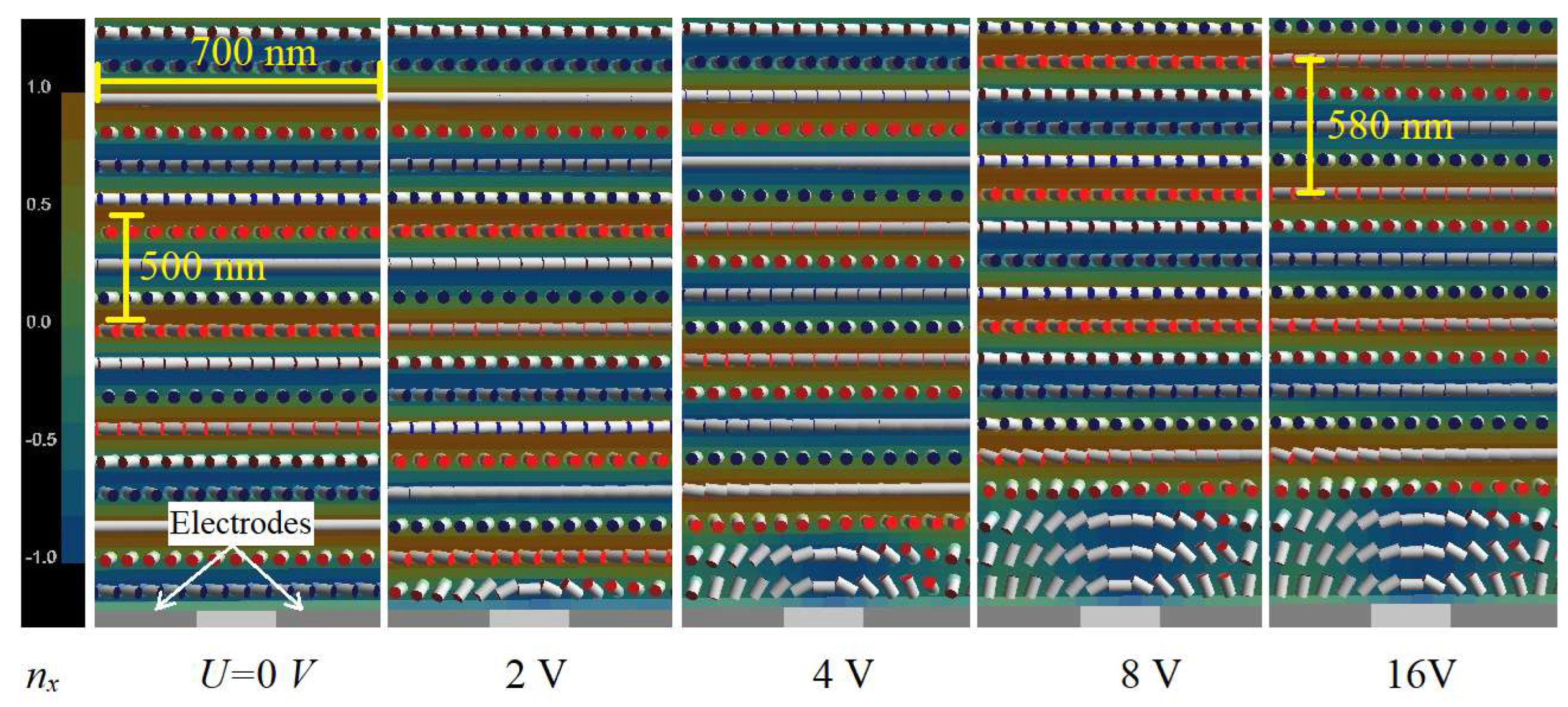
Quite promising results were simulated in the case where the electric field was strongly localized. Figure 5 shows the director distribution close to the homeotropic-alignment surface with the interdigitated electrodes of a submicron period of 700 nm and a gap between the electrodes of 200 nm. In this case, the electric field penetrates into the bulk only on a scale comparable with the spiral pitch (~500 nm), so the spiral across the layer thickness (d = 10 μm) remains stable.
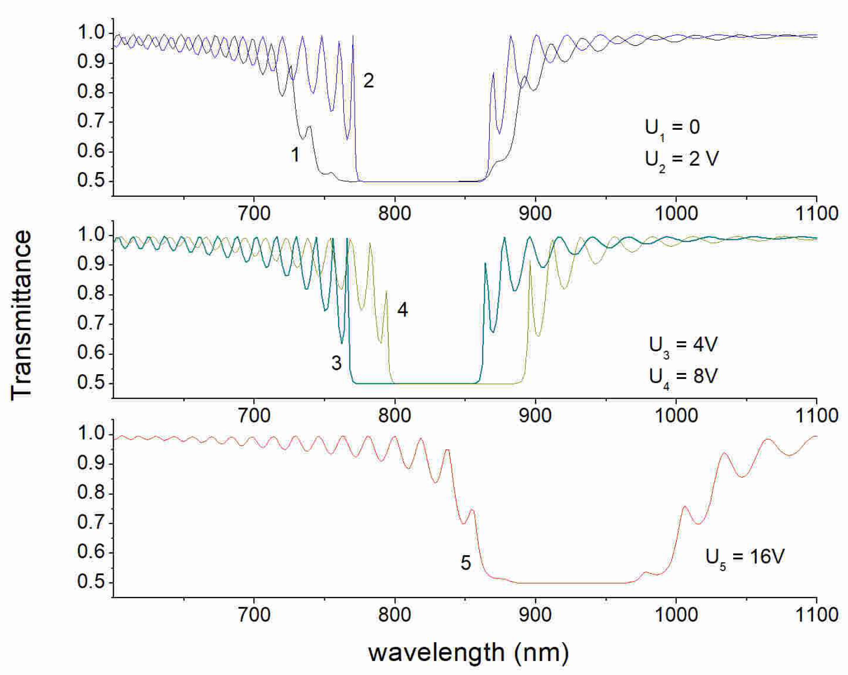
Because the width of the electrodes is significantly higher than the gap between the electrodes, the electric field is, on average, normal to the alignment surface, providing a tilted director orientation at the surface. This means that on average, we basically modify the zenithal anchoring strength, which results in a long-wavelength shift of the stop-band. The calculated spectra in Figure 6 show the pronounced stop-band shift more than 100 nm from a central wavelength of 815 nm (curve 1) up to about 930 nm at U = 16V (curve 5). This shift corresponds to changing the spiral pitch from 510 nm to about 580 nm. The shift, however, is not a regular one. At the lower voltages in a range of 2–4 V, a small shift to shorter wavelengths takes place. This can be explained by periodic flipping of the direction of the electric field vector from the horizontal to the vertical direction, so we still have multiple states defined by an effective field-induced azimuthal anchoring. Nevertheless, due to the local (near the surface) deformation, the spiral is stable over the time, and the pulse driving is not necessary to control the spectral stop-band position.
4. Conclusions
In conclusion, we found that in the case of hybrid boundary conditions, the spiral pitch in cholesteric LCs strongly depends on the zenithal anchoring strength at the homeotropic-alignment surface. The electric field from the planar system of electrodes located at this surface can effectively modify both azimuthal and zenithal anchoring strength. In cases where the gap between the electrodes is comparable or larger than the layer thickness, in addition to azimuthal anchoring modification, the electric field also results in deformation of the spiral across the layer thickness. In this case, one can observe both a second-order field-induced reflection band and an anomalous spectral shift of the principal stop-band to the shorter wavelengths. However, the spiral is unstable at these conditions, and the effect can be observed only in pulsed electric fields. The field-on stability of the spiral can be achieved in cases where the electric field is strongly localized on a scale of the spiral pitch near the alignment surface. This can be done using a short-pitch electrode grating located at the homeotropic-alignment surface. Using the localized electric field, the pitch of the cholesteric spiral and spectral position of the stop-band can be well controlled over a wide spectral range.
Author Contributions
Conceptualization, S.P.P., N.M.S. and N.M.S.; methodology, S.P.P. and N.M.S.; formal analysis, S.P.P. and N.M.S.; software, S.P.P.; investigation S.P.P., N.M.S. and B.A.U. and D.O.R.; writing S.P.P. All authors have read and agreed to the published version of the manuscript.
Funding
This work is supported by the Ministry of Science and Higher Education within a state assignment.
Conflicts of Interest
The authors declare no conflict of interest.
References
- de Gennes, P.G.; Prost, J. The Physics of Liquid Crystals; Oxford Science Publications: Oxford, UK, 1993. [Google Scholar]
- Belyakov, V.A. Diffraction Optics of Complex Structured Periodic Media; Springer: New York, NY, USA, 1992. [Google Scholar]
- Blinov, L.M. Structure and Properties of Liquid Crystals; Springer: New York, NY, USA, 2011. [Google Scholar]
- Kopp, V.I.; Zhang, Z.Q.; Genacka, A.Z. Lasing in chiral photonic structures. Prog. Quantum Electron. 2003, 27, 369–416. [Google Scholar] [CrossRef]
- Belyakov, V.A. From liquid crystals localized modes to localized modes in photonic crystals. J. Lasers Opt. Photonics 2017, 4, 153. [Google Scholar]
- Vetrov, S.Y.; Timofeev, I.V.; Shabanov, V.F. Localized modes in chiral photonic structures. Physics-Uspekhi 2020, 63, 33–35. [Google Scholar] [CrossRef]
- Ryabchun, A.; Bobrovsky, A. Cholesteric liquid crystal materials for tunable difractive optics. Adv. Opt. Mater. 2018, 6, 1800335. [Google Scholar] [CrossRef]
- Ortega, J.; Folcia, C.L.; Etxebarria, J.; Sierra, T. Ferroelectric chiral nematic liquid crystals: New photonic materials with multiple bandgaps controllable by low electric fields. Liq. Cryst. 2022, 45, 1518–1524. [Google Scholar] [CrossRef]
- Petriashvili, G.; Matranga, M.A.; De Santo, M.P.; Chilaya, G.; Barberi, R. Wide band gap materials as a new tuning strategy for dye doped cholesteric liquid crystals laser. Opt. Express 2009, 17, 4553–4558. [Google Scholar] [CrossRef]
- Meyer, R.B.; Lonberg, F.; Chang, C.C. Cholesteric liquid crystal smart reflectors. Mol. Cryst. Liq. Cryst. 1996, 288, 47–61. [Google Scholar] [CrossRef]
- Subacius, D.; Bos, P.; Lavrentovich, O. Switchable diffractive cholesteric gratings. Appl. Phys. Lett. 1997, 71, 1350–1352. [Google Scholar] [CrossRef] [Green Version]
- Hamdi, R.; Petriashvili, G.; De Santo, M.P.; Lombardo, G.; Barberi, R.C. Electrically controlled 1D and 2D cholesteric liquid crystal gratings. Mol. Cryst. Liq. Cryst. 2012, 553, 97–102. [Google Scholar] [CrossRef]
- Rumi, M.; White, T.J.; Bunning, T.J. Reflection spectra of distorted cholesteric liquid crystal structures in cells with interdigitated electrodes. Opt. Express 2014, 22, 16510. [Google Scholar] [CrossRef] [Green Version]
- Rumi, M.; Tondiglia, V.P.; Natarajan, L.V.; White, T.J.; Bunning, T.J. Non-Uniform Helix Unwinding of Cholesteric Liquid Crystals in Cells with Interdigitated Electrodes. ChemPhysChem 2014, 15, 1311. [Google Scholar] [CrossRef] [PubMed]
- Belyakov, V.A.; Kats, E.I. Surface anchoring and temperature variations of the pitch in thin cholesteric layers. JETP 2000, 91, 488. [Google Scholar] [CrossRef]
- Sarukhanyan, T.M.; Gharagulyan, H.; Rafayelyan, M.S.; Golik, S.S.; Alaverdyan, R.B. Multimode Robust Lasing in a Dye-Doped Polymer Layer Embedded in a Wedge-Shaped Cholesteric. Molecules 2021, 26, 6089. [Google Scholar] [CrossRef] [PubMed]
- Jeong, M.-Y.; Wu, J.W. Continuous spatial tuning of laser emission with tuning resolution less than 1 nm in a wedge cell of dye-doped cholesteric liquid crystals. Opt. Expess 2010, 18, 24221. [Google Scholar] [CrossRef] [Green Version]
- Meyer, R.B. Distortion of a cholesteric structure by a magnetic field. Appl. Phys. Lett. 1969, 14, 208. [Google Scholar] [CrossRef]
- de Gennes, P.G. Calcul de la distorsion d’une structure cholesterique par un champ magnetique. Solid State Commun. 1968, 6, 163. [Google Scholar] [CrossRef]
- Kahn, F.J. Electric-field-induced color changes and pitch dilation in cholesteric liquid crystals. Phys. Rev. Lett. 1970, 24, 209–212. [Google Scholar] [CrossRef]
- Chou, S.C.; Cheung, L.; Meyer, R.B. Effects of a magnetic field on the optical transmission in cholesteric liquid crystals. Solid State Commun. 1972, 11, 977. [Google Scholar] [CrossRef]
- Chigrinov, V.G.; Belyaev, V.V.; Belyaev, S.V.; Grebenkin, M.F. Instability of cholesteric liquid crystals in an electric field. Sov. Phys. JETP 1979, 50, 994–999. [Google Scholar]
- Berreman, D.W.; Heffner, W.R. New bistable liquid-crystal twist cell. J. Appl. Phys. 1981, 52, 3032. [Google Scholar] [CrossRef]
- Palto, S.P.; Barnik, M.I.; Geivandov, A.R.; Kasyanova, I.V.; Palto, V.S. Spectral and polarization structure of field-induced photonic bands in cholesteric liquid crystals. Phys. Rev. E 2015, 92, 032502. [Google Scholar] [CrossRef] [PubMed]
- Dozov, I.; Nobili, M.; Durand, G. Fast bistable nematic display using monostable surface switching. Appl. Phys. Lett. 1997, 70, 1179. [Google Scholar] [CrossRef]
- Palto, S.P. On mechanism of the helix pitch variation in a thin cholesteric layer confined between two surfaces. JETP 2002, 94, 260–269. [Google Scholar] [CrossRef]
- Choi, Y.; Yokoyama, H.; Gwag, S. Determination of surface nematic liquid crystal anchoring strength using nano-scale surface grooves. Opt. Express 2013, 21, 12135–12144. [Google Scholar] [CrossRef]
- Berreman, D.W. Optics in Stratified and Anisotropic Media: 4x4-Matrix Formulation. JOSA 1972, 62, 502–510. [Google Scholar] [CrossRef]
- Palto, S.P. An algorithm for solving the optical problem for stratified anisotropic media. JETP 2001, 92, 552–560. [Google Scholar] [CrossRef]
- Palto, S.P. The field-induced stop-bands and lasing modes in CLC layers with Deformed Lying Helix. Crystals 2019, 9, 469. [Google Scholar] [CrossRef] [Green Version]
- Palto, S.P. Simulation of electrooptical effects and dynamics of ferroelectric liquid crystals. Crystallogr. Rep. 2003, 48, 124–140. [Google Scholar] [CrossRef]
- Rapini, A.; Papoular, M. Distorsion d’une lamelle nématique sous champ magnétique conditions d’ancrage aux parois. J. Phys. Coll. 1969, 30, 54–56. [Google Scholar] [CrossRef]
- Shtykov, N.M.; Palto, S.P.; Umanskii, B.A.; Rybakov, D.O.; Simdyankin, I.V. Director Distribution in a CLC Hybrid Cell with a Small Helicoidal Pitch. Crystallogr. Rep. 2023. to be published. [Google Scholar]
Figure 1.
Schematic representation of two types of samples: (a) the homeotropic alignment is implemented on the bottom substrate with planar electrodes, and planar alignment is on the top substrate (alignment of the easy axis is along the electrode strips); (b) the planar alignment on the bottom substrate with electrodes, with the easy axis along the electrode strips; the top substrate provides the homeotropic alignment.

Figure 2.
Transmittance spectra for samples “A” (a) and “B” (b) at different magnitudes of the driving voltage Up-p: 0, 100, 200, and 300 V for the curves 1, 2, 3, and 4, respectively.
Figure 2.
Transmittance spectra for samples “A” (a) and “B” (b) at different magnitudes of the driving voltage Up-p: 0, 100, 200, and 300 V for the curves 1, 2, 3, and 4, respectively.

Figure 3.
Illustration of the graphic solution of Equation (8). A subset of the designated intersection points corresponds to a local minimum of free energy.
Figure 3.
Illustration of the graphic solution of Equation (8). A subset of the designated intersection points corresponds to a local minimum of free energy.

Figure 4.
Optical transmittance spectra with the electric field switched off (curves 1, 3) and switched on (curves 2, 4) at voltage U = 100 V for two values of the zenithal anchoring energy on the homeotropic-alignment surface: Wz = 0.025 mJ/m2 (top); Wz = 0.05 mJ/m2 (bottom).
Figure 4.
Optical transmittance spectra with the electric field switched off (curves 1, 3) and switched on (curves 2, 4) at voltage U = 100 V for two values of the zenithal anchoring energy on the homeotropic-alignment surface: Wz = 0.025 mJ/m2 (top); Wz = 0.05 mJ/m2 (bottom).

Figure 5.
Equilibrium distribution of the LCD director near the homeotropic-alignment surface with weak anchoring (Wz = 0.01 mJ/m2) for different values of voltage on interdigitated electrodes (electrode width 500 nm; gap between electrodes 200 nm). Images correspond to the xz plane (x-axis is horizontal direction, perpendicular to the electrode strips; the z-axis is vertical (normal to the plane of the CLC layer and corresponds to the spiral axis). The color scale corresponds to the x-component of the LC director.

Figure 6.
Transmittance spectra of the CLC layer for different values of electrical voltage U on the interdigitated electrodes: (1) U = 0 V; (2) U = 2V; (3) U = 4V; (4) U = 8V; (5) U = 16V. The corresponding director distributions are shown in Figure 5.
Figure 6.
Transmittance spectra of the CLC layer for different values of electrical voltage U on the interdigitated electrodes: (1) U = 0 V; (2) U = 2V; (3) U = 4V; (4) U = 8V; (5) U = 16V. The corresponding director distributions are shown in Figure 5.

Disclaimer/Publisher’s Note: The statements, opinions and data contained in all publications are solely those of the individual author(s) and contributor(s) and not of MDPI and/or the editor(s). MDPI and/or the editor(s) disclaim responsibility for any injury to people or property resulting from any ideas, methods, instructions or products referred to in the content. |
© 2022 by the authors. Licensee MDPI, Basel, Switzerland. This article is an open access article distributed under the terms and conditions of the Creative Commons Attribution (CC BY) license (https://creativecommons.org/licenses/by/4.0/).
Share and Cite
MDPI and ACS Style
Palto, S.P.; Rybakov, D.O.; Umanskii, B.A.; Shtykov, N.M. Spiral Pitch Control in Cholesteric Liquid Crystal Layers with Hybrid Boundary Conditions. Crystals 2023, 13, 10. https://0-doi-org.brum.beds.ac.uk/10.3390/cryst13010010
AMA Style
Palto SP, Rybakov DO, Umanskii BA, Shtykov NM. Spiral Pitch Control in Cholesteric Liquid Crystal Layers with Hybrid Boundary Conditions. Crystals. 2023; 13(1):10. https://0-doi-org.brum.beds.ac.uk/10.3390/cryst13010010
Chicago/Turabian StylePalto, Serguei P., Dmitry O. Rybakov, Boris A. Umanskii, and Nikolay M. Shtykov. 2023. "Spiral Pitch Control in Cholesteric Liquid Crystal Layers with Hybrid Boundary Conditions" Crystals 13, no. 1: 10. https://0-doi-org.brum.beds.ac.uk/10.3390/cryst13010010
Note that from the first issue of 2016, this journal uses article numbers instead of page numbers. See further details here.