Synthesis and Characterization of AlCoCrFeNiNbx High-Entropy Alloy Coatings by Laser Cladding

1
College of Mechanical and Electronic Engineering, Shandong University of Science and Technology, Qingdao 266590, China
2
Key Laboratory of Solidification Control and Digital Preparation Technology (Liaoning Province), School of Materials Science and Engineering, Dalian University of Technology, Dalian 116024, China
*
Author to whom correspondence should be addressed.
Crystals 2019, 9(1), 56; https://0-doi-org.brum.beds.ac.uk/10.3390/cryst9010056
Submission received: 11 December 2018
/
Revised: 8 January 2019
/
Accepted: 10 January 2019
/
Published: 20 January 2019
Abstract
:AlCoCrFeNiNbx (x in molar ratio x = 0, 0.25, 0.5, 0.75, and 1.0) high-entropy alloy (HEA) coatings were manufactured on 304 stainless steel by laser cladding. The constituent phases, microstructures, chemical composition, micro-hardness and wear resistance of the HEA coatings were investigated respectively by X-ray diffraction (XRD), scanning electron microscopy (SEM), energy-dispersive spectroscopy (EDS), a Vickers hardness tester and a friction/wear testing machine. It was found that an AlCoCrFeNi alloy coating without Nb consisted of body-centered-cubic (BCC) and order BCC (B2) phases, while the AlCoCrFeNiNbx (x > 0) alloy coatings consisted of BCC, B2 and Laves phases. Microstructures of the AlCoCrFeNiNbx alloy coatings evolved from equiaxed grain (x = 0) to hypoeutectic (0.25 ≤ x < 0.75), then to full eutectic (x = 0.75), and finally to hypereutectic (x > 0.75). With increasing Nb content, the Vickers hardness values increased. AlCoCrFeNiNb0.75 alloy coating with a fully eutectic microstructure demonstrated the best wear resistance among the AlCoCrFeNiNbx (x ≥ 0) alloy coatings.
1. Introduction
Generally, traditional alloys consist of one main element, whereas high entropy alloys (HEAs) are usually composed of five or more elements and their concentrations range from 5–35 at. % (atomic percent) [1,2,3]. The unique component design brings four core effects: high entropy effect, lattice distortion effect, sluggish diffusion and cocktail effect. Due to these effects, HEAs usually consist of simple solid solution structures, nano-structures or can even be amorphous [4,5,6] and they possess excellent properties such as high strength, good thermal stability, good electrical and magnetic performance and excellent corrosion and wear resistance [7,8,9,10,11,12,13,14,15,16,17]. Thus, HEAs have been extensively studied because of the unique design conception and their excellent properties.
Until now, many different methods have been successfully applied to synthesize HEAs [18], such as vacuum arc furnace, laser cladding, selective electron beam melting, laser engineered net shaping and so on. Among them, laser cladding, which melts the materials using a high energy density laser beam, is widely adopted to fabricate HEAs [19]. There are several advantages of laser cladding: firstly, the solidification rate is much faster than that of other fabrication methods so that a fine microstructure is obtained and many defects can be avoided during the laser cladding process [20]; secondly, the flexible and controllable working parameters give opportunities for different raw materials to form a thought-fitted layer. Additionally, the laser cladding technique will obviously reduce the cost, because the HEA coatings need less raw materials than other techniques such as arc melting [21]. Therefore, the laser cladding technique will undoubtedly become promising among various synthesis methods.
The AlCoCrFeCuNi alloy, with outstanding mechanical properties, was the first and most studied HEA system [1,22,23]. After that, the Cu element was removed because it easily segregates in the interdendritic region, deteriorating the mechanical properties of the alloy. Therefore, AlCoCrFeNi HEAs have been widely studied by many researchers [24,25,26,27,28,29,30]. Wang [28] discovered that the AlCoCrFeNi alloy displayed excellent mechanical properties, in which the yield strength, compressive strength and plastic strain reached 1250.96 MPa, 2004.23 MPa, and 32.7%, respectively. Kunce [30] fabricated a AlCoCrFeNi HEA through laser engineered net shaping and found that with an increase in laser scanning rate, the average grain size of the alloy decreased, resulting in the increment of micro-hardness. In addition, the effects of the addition of a secondary element such as Ti, V, C or Nb [31,32,33,34] into the AlCoCrFeNi alloy have also been studied in order to further tailor their microstructures and properties. Ma [34] added the Nb element into the AlCoCrFeNi HEA. The AlCoCrFeNiNbx alloys were fabricated using arc melting and the results showed that the alloys exhibited a eutectic microstructure and high strength/hardness. The high strength/hardness might result in outstanding wear resistance. Moreover, the AlCoCrFeNiNbx alloys fabricated by laser cladding were rarely researched.
Thus, in this study, laser cladding was employed to synthesize the AlCoCrFeNiNbx (x = 0, 0.25, 0.5, 0.75, and 1.0) HEAs on 304 stainless steel in order to enhance the wear resistance of the substrate. Then, the microstructure and mechanical properties (Vickers hardness and wear resistance) of the AlCoCrFeNiNbx HEA coatings were investigated.
2. Materials and Methods
The alloys of AlCoCrFeNiNbx (x value in molar ratio, x = 0, 0.25, 0.5, 0.75, and 1.0, denoted as Nb0, Nb0.25, Nb0.5, Nb0.75, and Nb1.0, respectively) were prepared. Al, Co, Cr, Fe, Ni and Nb powders with purity higher than 99.5% were used as the raw materials. The 304 stainless steel was applied as the substrate with a size of 25 mm × 15 mm × 8 mm in this work and the compositions were listed in Table 1. The substrates were treated with 180-grit abrasive paper to remove surface oxides and contaminants. Before the laser cladding, the HEA powders were placed onto the surface of the 304 stainless steel to form the powder bed with a thickness of 1.2 mm. Laser cladding was carried out by a semiconductor-type laser processing machine (LWS-500 Laserline, Koblenz, Germany). The parameters were: laser power = 1000 W, spot diameter = 3 mm, scan speed = 7 mm/s, and the high-purity argon was supplied to create a protective atmosphere during the laser cladding process.
The samples were cut perpendicular to the laser scanning direction. Half an alloy was ground, polished, and etched with alcohol dilute aqua regia for microstructure observation, while the remaining half was ground and polished for crystal structure and friction wear testing. The identification of constituent phases was accomplished by x-ray diffraction (XRD, XRD, Bruker, Ettlingen, Germany) with Co Kα radiation at 30 kV and 15 mA, a scanning speed of 5°/min and 2θ ranging from 30° to 120°. The microstructure and chemical composition of the coatings were measured using a field-emission-gun scanning electron microscope (SEM, Zeiss Supra 55, Oberkochen, Germany) with a working distance of 11 mm equipped and an energy-dispersive spectrometer (EDS). The Vickers hardness tester (MH-6L) was used to get the hardness values from the top of the HEAs coating to the 304 stainless steel substrate with a load of 4.9 N and a duration time of 15 s. The wear resistance was tested by a wear testing machine (CFT-I, Zhongke Kaihua, Lanzhou, China) under dry sliding friction. The test load of 10 N and a duration time of 30 min were used during wear testing and a Si3N4 ceramic ball with a diameter of 3 mm was selected as a counterpart. The worn surfaces of the samples were characterized by SEM. The depth and width of the worn surface were measured by a confocal laser scanning microscope (LEXT OLS4000, Olympus, Tokyo, Japan).
3. Results and Discussion
3.1. Phase Analysis
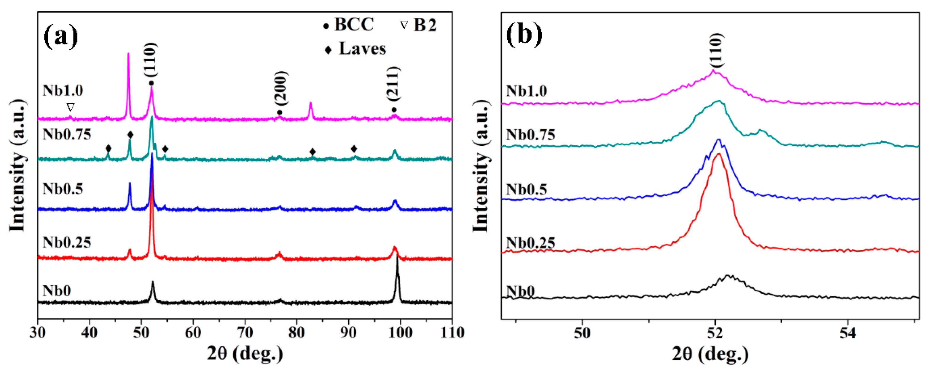
The XRD patterns of AlCoCrFeNiNbx (x = 0, 0.25, 0.5, 0.75, and 1.0) HEA coatings were shown in Figure 1a. It can be found that the Nb0 alloy coating only appeared in body-centered-cubic (BCC) diffraction peaks. Small peaks near 36° correspond to 001 reflections of the order BCC (B2) phase. The constituent phases of the AlCoCrFeNi laser cladding coating were the same as that of the arc melting ingot [35]. With the addition of Nb, the new diffraction peaks of the Laves phase appeared and the intensity was enhanced. Figure 1b gave the detailed scans for the (110) peak of the BCC solid solution phase. The peak of (110)BCC shifting to the lower 2θ with the increased Nb content indicates that the lattice parameters of the BCC solid solution phase increased. The lattice parameter (a) of the BCC solid solution were 2.8737 Å, 2.8828 Å, 2.8833 Å, 2.8830 Å and 2.8839 Å for Nb0, Nb0.25, Nb0.5, Nb0.75 and Nb1.0, respectively, which were calculated using the Bragg equation from the (110)BCC peak. The ε (ε = △a/a0, where △a =∣a−a0∣) [36] was used to evaluate the lattice strain of the BCC phase, wherein a0 was the lattice parameter of the Nb0 alloy coating, which was regarded as a “perfect” alloy. Results indicated that the lattice strain of the BCC phase of AlCoCrFeNiNbx increases with the increase in Nb content. The Nb1.0 alloy coating had the highest ε, indicating the largest lattice strain.
3.2. Microstructures
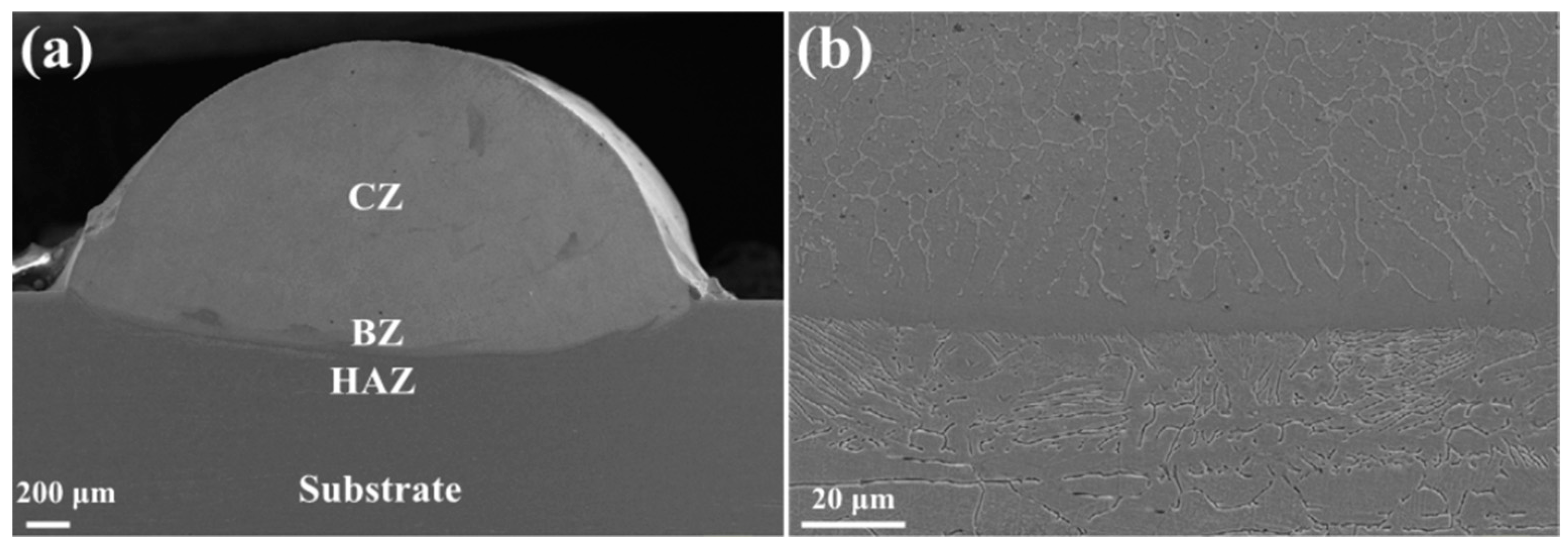
The micrographs of a cross-section and bonding zone were presented in Figure 2. As can be seen in Figure 2a, the cross-section showed a typical laser cladding shape with a width of about 3 mm and a thickness of about 1.2 mm and consisted of a cladding zone (denoted by CZ), bonding zone (denoted by BZ), heat-affected zone (denoted by HAZ) and substrate. There were no obvious holes, cracks or other defects in these alloy coatings. The distinct long, smooth bonding line was clearly seen at the interface of the coating and the substrate (seen in Figure 2b), which indicated a high-quality metallurgical combination between the HEA coating and the substrate. Different microstructures could be seen from BZ to CZ because the solidification microstructure depends on the temperature gradient of liquid (GL) and solidification rate (SR). Near the substrate, GL was large while SR tended to zero, so the value of GL/SR was very large and planar growth occurred. The GL/SR value decreased continually from the solid–liquid interface to the top of the molten pool and the microstructure changed from planar to columnar and then to equiaxed grain accordingly [37]. Table 2 displayed the EDS results from the bonding zone (BZ) for all coatings. It could be seen that the Fe content in the BZ was much higher than the nominal content but lower than that of the substrate for all samples. The reason for this might be that the Fe atom diffused from the 304 stainless steel substrate to the HEA coating during the laser cladding process. However, the atom diffusion happened in a short time and in a limited region, which ensured that the chemical composition of the HEA coating was close to that of the designed content.
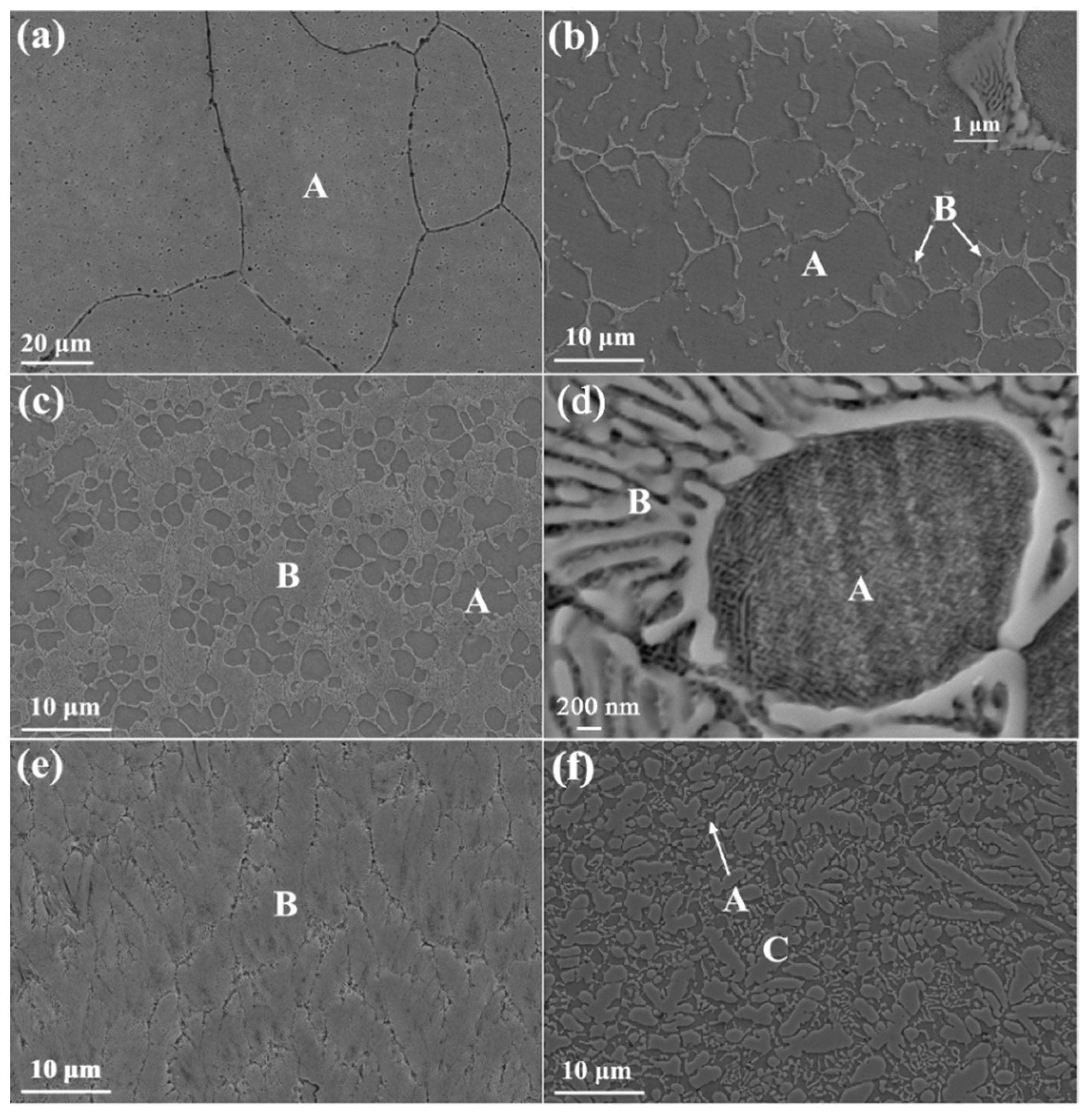
Figure 3 presented the microstructures of the CZ in AlCoCrFeNiNbx (x = 0, 0.25, 0.5, 0.75, 1.0) alloy coatings. For the Nb0 alloy coating, the equiaxed grain structure exhibited modulated basket-weave morphology particles as shown in Figure 3a. Similar results have been reported in the literature [38,39]. When Nb was added into the AlCoCrFeNi alloy, the microstructure changed significantly. From Figure 3b, we can see that the Nb0.25 alloy coating had a dendritic morphology, which consisted of modulated basket-weave morphology and lamellar microstructure in the dendritic (denote by A) and interdendritic regions (denoted by B), respectively. This indicated that the Nb0.25 alloy coating was hypoeutectic. With the increase of Nb content, the volume fraction of the lamellar microstructure increases. A typical hypoeutectic microstructure consisting of a dark flowery region (denote by A) and a eutectic region (denoted by B) was obtained for the Nb0.5 alloy coating, as shown in Figure 3c. From the high magnification SEM image of the Nb0.5 alloy coating (seen in Figure 3d), it can be found that region A also demonstrated a modulated structure with the basket-weave morphology, and region B showed the thin lamellar eutectic structure. The Nb0.75 alloy coating showed a full eutectic microstructure, as shown in Figure 3e. When the Nb content reached 1.0, the primary phase (denoted by C) appeared, indicating that the Nb1.0 alloy coating was hypereutectic.
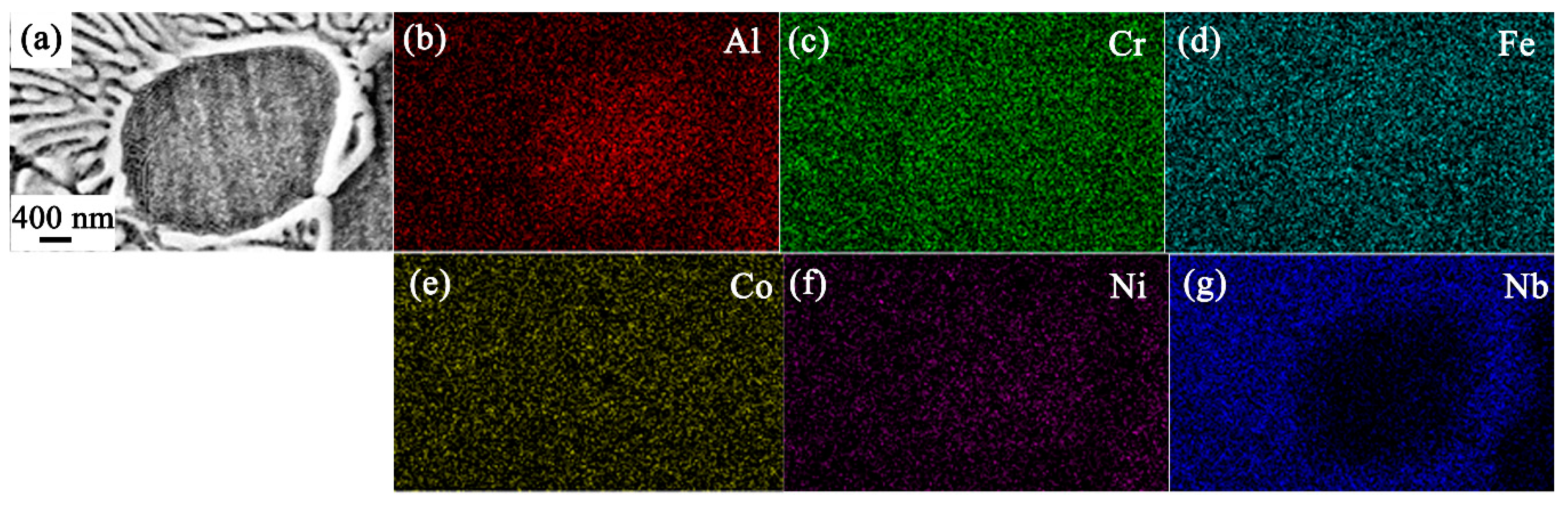
Table 3 displayed the EDS results of the coating zone (CZ) for all coatings. Figure 4 shows the EDS mapping of the AlCoCrFeNiNb0.5 alloy. It can be found that for the AlCoCrFeNiNbx (x > 0) alloy coatings, region A was enriched in Al and Ni elements while the Nb element was depleted. On the contrary, region C was enriched in the Nb element. Combined with the EDS and XRD results, region A was an Al, Ni-rich BCC and B2 phase, while region C was a Nb-rich Laves phase. The atom radius of the Nb element was the largest among all the alloying elements. So limited Nb element was dissolved into the AlCoCrFeNi alloy while the rest of the Nb element yielded the formation of the Nb-rich Laves phase. Furthermore, the Al–Ni atom pair possessed a very negative mixing enthalpy (−22 kJ/mol) [40] and tended to combine to form the Al, Ni-rich phase. It was concluded that the microstructures of AlCoCrFeNiNbx (x = 0, 0.25, 0.5, 0.75, 1.0) alloy coatings changed from BCC and B2 structure (x = 0) to hypoeutectic with primary BCC a B2 phases (0.25 ≤ x < 0.75) then to eutectic with a mixture of BCC, B2 and Laves phases (x = 0.75) and finally to hypereutectic with a primary Laves phase (0.75 < x ≤ 1).
3.3. Vickers Hardness
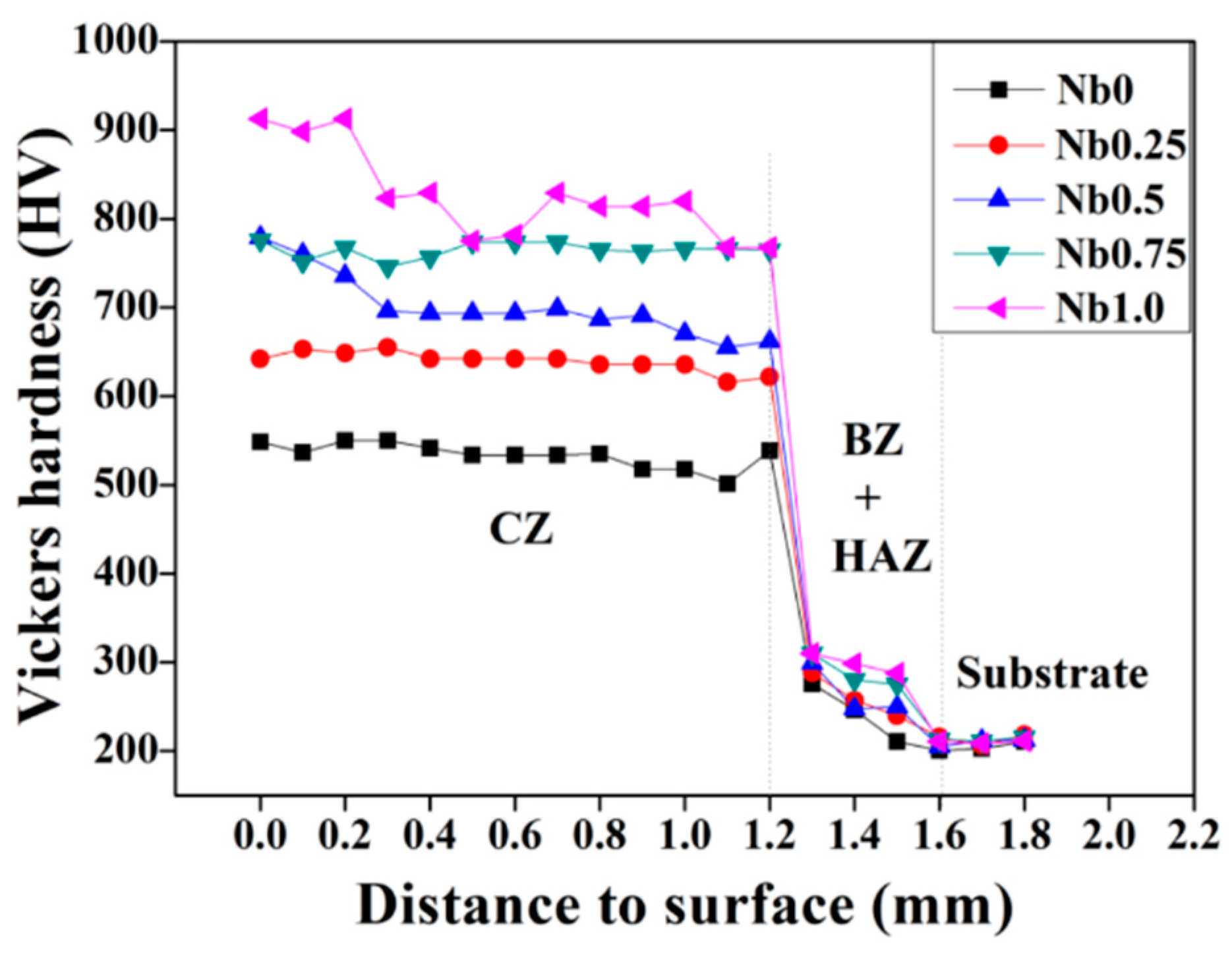
The Vickers hardness values for AlCoCrFeNiNbx (x = 0, 0.25, 0.5, 0.75, and 1.0) alloy coatings were displayed in Figure 5, which tested from the top of the coating to the substrate. With the increment of Nb content of AlCoCrFeNiNbx alloy coatings, the Vickers hardness increased. The Nb1.0 alloy coating showed the highest hardness value of 913 HV, which was almost four times higher than that of the 304 substrate. The high hardness of AlCoCrFeNiNbx alloy coatings might be ascribed to several reasons: firstly, the Nb atom is larger in size compared to the other five alloying atoms; some Nb element dissolved in the BCC/B2 solid solution phase could result in solid solution strengthening. Secondly, the Laves phase was a kind of hard phase which contributed to the high hardness. For the AlCoCrFeNiNbx (x = 0.25, 0.5, 0.75, 1.0) alloys, the volume fractions of the Laves phase are 15%, 32.7%, 52%, 66%, respectively. The increased volume fraction of the Laves phase with increasing Nb content led to the enhancement of Vickers hardness.
3.4. Wear Resistance
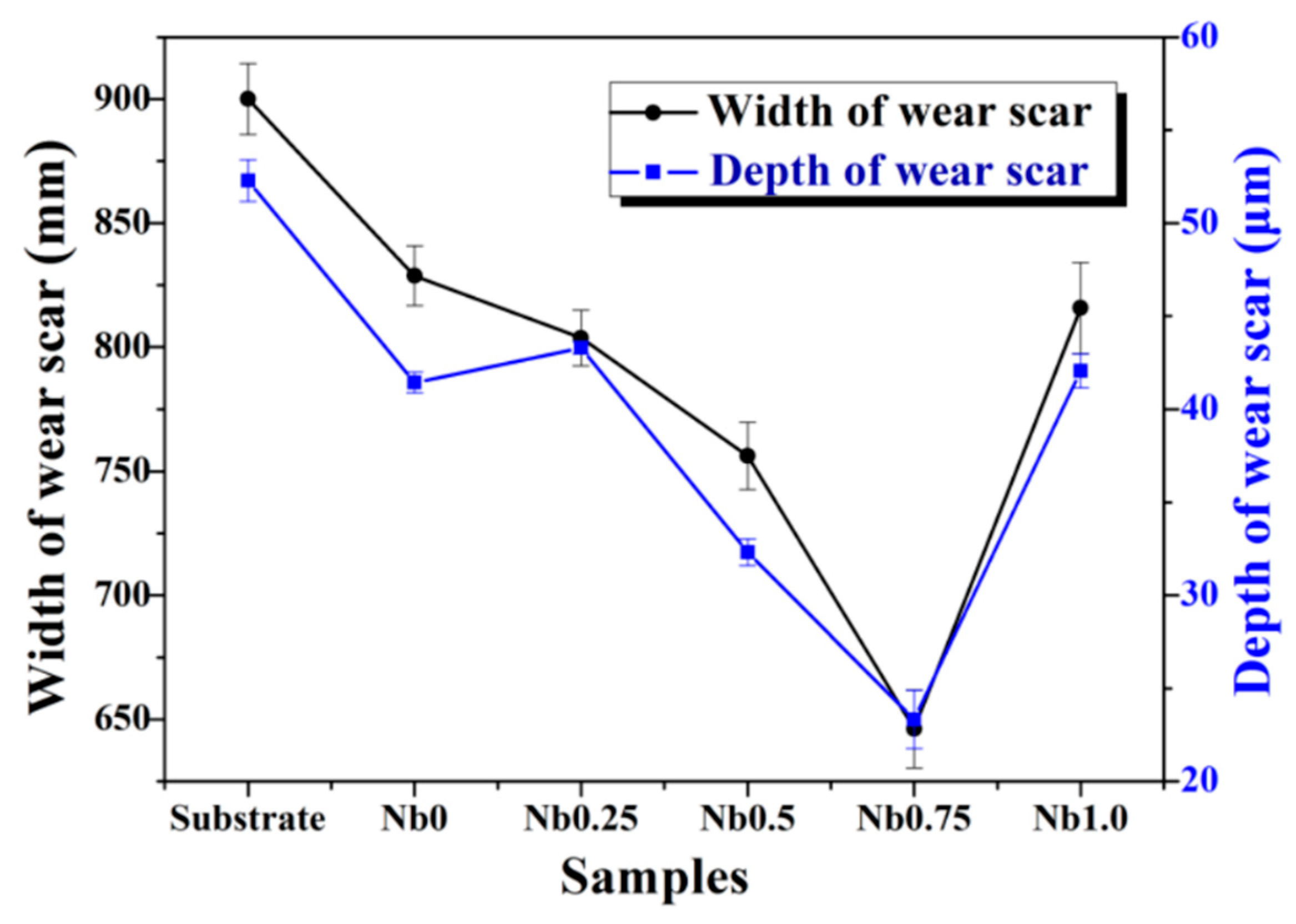
Figure 6 showed the wear scar width and depth of the substrate and the AlCoCrFeNiNbx alloy coatings. The wear scar of the 304 stainless steel substrate was the widest and deepest among all samples. In AlCoCrFeNiNbx alloy coatings, with the increase of Nb content from 0 to 0.75, the wear width and depth decreased. Further increasing the Nb content to 1.0, the wear width and depth increased, indicating the wear resistance got worse. The Nb0.75 alloy coating with the smallest value of wear scar width and depth indicated the best wear resistance. The excellent wear resistance of the Nb0.75 eutectic HEA coating resulted from the ductile BCC and B2 phases and the hard Laves phase coupled interaction. During the wear process, the hard Laves phase can play a role in resisting adhesive wear, and the soft BCC and B2 phases can support the hard and brittle Laves phase to prevent the expansion of brittle cracks. The interaction of the two phases improves the wear resistance of the alloy.
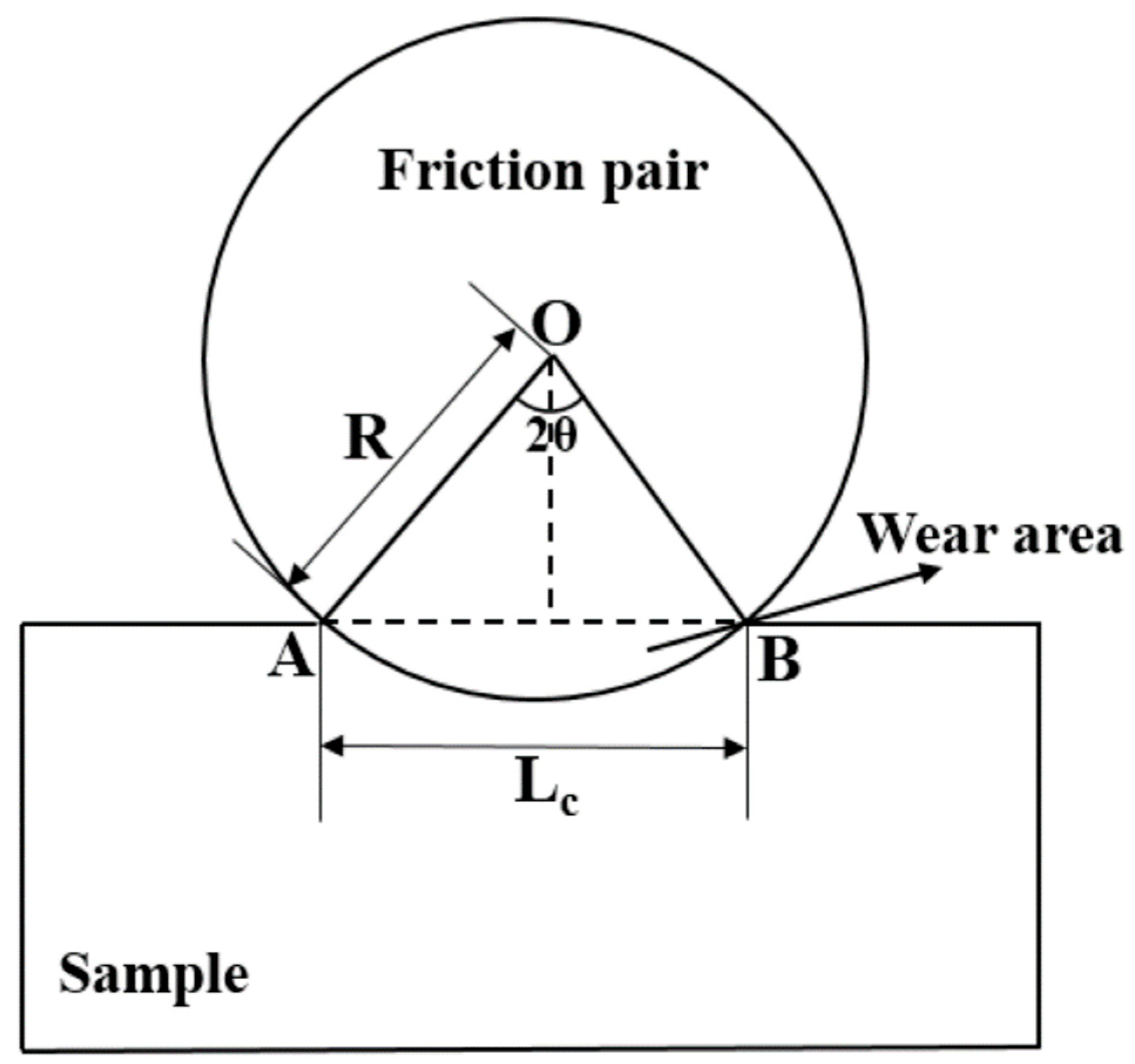
In order to further assess the wear resistance of the samples, wear data was obtained. Figure 7 shows the schematic of the calculation principal of wear volume (V), wherein, OA(R) is the radius of the friction pair, AB (Lc) is the wear scar width, L is the wear scar length, 2θ is the center angle of the grinding mark width AB, and θ can be estimated as:
St is the area of triangle OAB, which can be estimated as:
Ss is the area of sector OAB, which can be estimated as:
The wear area (S) can be expressed as: S = Ss − St. Therefore, wear volume (V) can be expressed as:
The calculated wear cross section and wear volume of the AlCoCrFeNiNbx alloy coatings are listed in Table 4. As observed in Table 4, the wear area and wear volume of the substrate were higher than that of the AlCoCrFeNiNbx alloy coatings, indicating that the alloy coatings possessed better wear resistance compared to the substrate. In addition, with the increase in Nb content, the wear area and wear volume of the AlCoCrFeNiNbx alloy coatings first decreased (0 ≤ x ≤ 0.75) and then increased (x > 0.75), which was consistent with the change trend of the wear scar width and depth. This indicated that the wear rate of AlCoCrFeNiNbx alloy coatings first decreased and then increased. The AlCoCrFeNiNb0.75 alloy coating possessed the best wear resistance.
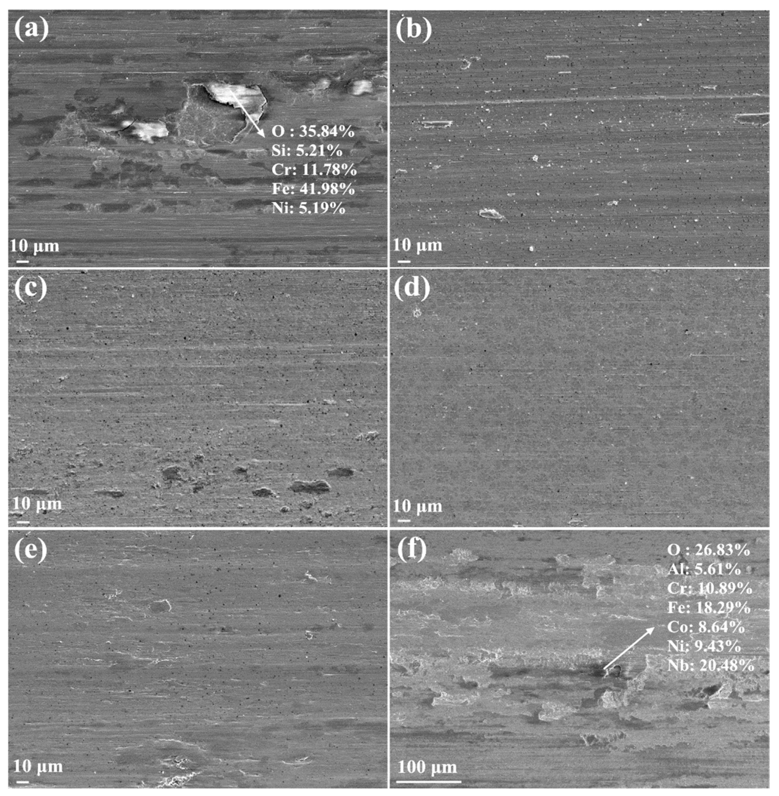
To investigate the wear behavior of AlCoCrFeNiNbx alloys coatings and the substrate, worn surfaces were observed using SEM. The results are shown in Figure 8. From Figure 8a, heavy scuffing and serious peeling could be seen on the 304 stainless steel substrate. Because the hardness of 304 stainless steel (250 HV) was much lower than that of the counterpart Si3N4 ball (1000 HV), the substrate was too soft to resist plastic deformation from the hard counterpart, causing heavy scuffing. The high temperature caused by the fast to-and-fro friction led to material oxidation, and then big pieces of material peeled off from the substrate. From the EDS results shown in Figure 8a, it can be found that the oxygen content was higher. Thus, for the substrate, abrasive wear is predominant and accompanied by oxidation wear and adhesive wear. For AlCoCrFeNiNbx (x = 0, 0.25, 0.5, and 0.75) alloy coatings, only a few wear debris and shallow scuffing was observed as shown in Figure 8b–e, indicating good wear resistance. This resulted from the higher hardness of alloy coatings—hard alloys can prevent severe plastic deformation when suffering wear and friction. The Nb0.75 alloy coating showed a very slight trace of abrasive wear and little material transfer as shown in Figure 8e. However, from Figure 8f, slight scuffing and obvious material loss could be seen on the surface of the Nb1.0 alloy coating. The Nb1.0 alloy coating has the largest hardness among all the alloys, which makes it brittle. During the wear test process, the hard material peeling off from the surface of the Nb1.0 alloy coating played a role of wedges [41]. Thus, adhesive wear was the dominating wear mechanism in the Nb1.0 alloy coating. Oxidation happened in all samples, which was verified by the EDS result in Figure 8f, indicating that the oxidation wear also was one of the wear mechanisms during the wear test. In conclusion, the dominant wear mechanism of AlCoCrFeNiNbx (x = 0, 0.25, 0.5, 0.75 and 1.0) alloy coatings changes from abrasive wear (x = 0–0.75) to adhesive wear (x = 1.0).
4. Conclusions
The AlCoCrFeNiNbx (x = 0, 0.25, 0.5, 0.75 and 1.0) alloy coatings were successfully synthesized by laser cladding on 304 stainless steel substrate. All the alloy coatings exhibited uniform microstructures, high hardness and excellent wear resistance compared to the substrate. The microstructures of the AlCoCrFeNiNbx (x = 0–1.0) alloy coatings evolved from equiaxed grain with BCC and B2 phases (x = 0) to hypoeutectic with primary BCC and B2 phases (0.25 ≤ x < 0.75), then to full eutectic with a mixture of BCC and B2 and Laves phases (x = 0.75) and finally to hypereutectic with a primary Laves phase (x = 1.0). In AlCoCrFeNiNbx (x = 0–1.0) alloy coatings, with the increase of Nb content, the Vickers hardness values increased. The Nb1.0 alloy coating showed the highest hardness value of 913 HV, which was almost four times higher than that of the substrate. Both the solid solution strengthening and larger volume fraction of the hard Laves phase contributed to the larger hardness value of alloy coatings. The AlCoCrFeNiNb0.75 alloy coating with a fully eutectic microstructure demonstrated the best wear resistance among the AlCoCrFeNiNbx alloy coatings tested.
Author Contributions
The experiment was designed by H.J. and D.L. The result analysis was performed by H.J. and D.L. H.J., K.H. and Z.C. were responsible for writing the paper.
Funding
This work was supported by the National Natural Science Foundation of China (Numbers 51671044, 51471044, 51525401 and 51574058), Dalian Support Plan for Innovation of High-level Talents (Top and Leading Talents, 2015R013), the Fundamental Research Funds for the Central Universities, and the National Key Research and Development Program of China (No.2016YB0701203).
Conflicts of Interest
The authors declare no conflict of interest.
References
- Yeh, J.W.; Chen, S.K.; Lin, S.J.; Gan, J.Y.; Chin, T.S.; Shun, T.T.; Tsau, C.H.; Chang, S.Y. Nanostructured High-Entropy Alloys with Multiple Principal Elements: Novel Alloy Design Concepts and Outcomes. Adv. Eng. Mater. 2004, 6, 299–303. [Google Scholar] [CrossRef]
- Zhang, Y.; Zuo, T.T.; Tang, Z.; Gao, M.C.; Dahmen, K.A.; Liaw, P.K.; Lu, Z.P. Microstructures and properties of high-entropy alloys. Prog. Mater. Sci. 2014, 61, 1–93. [Google Scholar] [CrossRef]
- Gao, M.C.; Yeh, J.W.; Liaw, P.K.; Zhang, Y. High Entropy Alloys Fundamentals and Applications; Springer International Publishing: Cham, Switzerland, 2016. [Google Scholar]
- Miracle, D.B.; Senkov, O.N. A critical review of high entropy alloys and related concepts. Acta Mater. 2017, 122, 448–511. [Google Scholar] [CrossRef] [Green Version]
- Ye, Y.F.; Wang, Q.; Lu, J.; Liu, C.T.; Yang, Y. High-entropy alloy: Challenges and prospects. Mater. Today 2016, 19, 349–362. [Google Scholar] [CrossRef]
- Schuh, B.; Mendez-Martin, F.; Völker, B.; George, E.P.; Clemens, H.; Pippan, R.; Hohenwarter, A. Mechanical properties, microstructure and thermal stability of a nanocrystalline CoCrFeMnNi high-entropy alloy after severe plastic deformation. Acta Mater. 2015, 96, 258–268. [Google Scholar] [CrossRef] [Green Version]
- Dong, Y.; Lu, Y.P.; Kong, J.R.; Zhang, J.J.; Li, T.J. Microstructure and mechanical properties of multi-component AlCrFeNiMox high-entropy alloys. J. Alloys Compd. 2013, 573, 96–101. [Google Scholar] [CrossRef]
- Xian, X.; Zhong, Z.H.; Zhang, B.W.; Song, K.J.; Chen, C.; Wang, S.; Cheng, J.G.; Wu, Y.C. A high-entropy V35Ti35Fe15Cr10Zr5 alloy with excellent high-temperature strength. Mater. Des. 2017, 121, 229–236. [Google Scholar] [CrossRef]
- Zuo, T.T.; Gao, M.C.; Ouyang, L.Z.; Yang, X.; Cheng, Y.Q.; Feng, R.; Chen, S.Y.; Liaw, P.K.; Hawk, J.A.; Zhang, Y. Tailoring magnetic behavior of CoFeMnNiX (X = Al, Cr, Ga, and Sn) high entropy alloys by metal doping. Acta Mater. 2017, 130, 10–18. [Google Scholar] [CrossRef]
- Zhang, Y.; Zuo, T.T.; Cheng, Y.Q.; Liaw, P.K. High-entropy alloys with high saturation magnetization, electrical resistivity, and malleability. Sci. Rep. 2013, 3, 1455. [Google Scholar] [CrossRef]
- Shi, Y.Z.; Yang, B.; Xie, X.; Brechtl, J.; Dahmen, K.A.; Liaw, P.K. Corrosion of AlxCoCrFeNi high-entropy alloys: Al-content and potential scan-rate dependent pitting behavior. Corros. Sci. 2017, 119, 33–45. [Google Scholar] [CrossRef]
- Shang, C.Y.; Axinte, E.; Sun, J.; Li, X.T.; Li, P.; Du, J.W.; Qiao, P.C.; Wang, Y. CoCrFeNi(W1−xMox) high-entropy alloy coatings with excellent mechanical properties and corrosion resistance prepared by mechanical alloying and hot pressing sintering. Mater. Des. 2017, 117, 193–202. [Google Scholar] [CrossRef]
- Yu, Y.; Wang, J.; Li, J.S.; Yang, J.; Kou, H.C.; Liu, W.M. Tribological Behavior of AlCoCrFeNi(Ti0.5) High Entropy Alloys under Oil and MACs Lubrication. J. Mater. Sci. Technol. 2016, 32, 470–476. [Google Scholar] [CrossRef]
- Feng, W.; Qi, Y.; Wang, S. Effects of Short-Range Order on the Magnetic and Mechanical Properties of FeCoNi(AlSi)x High Entropy Alloys. Metals 2017, 7, 482. [Google Scholar] [CrossRef]
- Klimova, M.; Stepanov, N.; Shaysultanov, D.; Chernichenko, R.; Yurchenko, N.; Sanin, V.; Zherebtsov, S. Microstructure and Mechanical Properties Evolution of the Al, C-Containing CoCrFeNiMn-Type High-Entropy Alloy during Cold Rolling. Materials 2017, 11, 53. [Google Scholar] [CrossRef] [PubMed]
- Moravcik, I.; Gouvea, L.; Cupera, J.; Dlouhy, I. Preparation and properties of medium entropy CoCrNi/boride metal matrix composite. J. Alloy. Compd. 2018, 748, 979–988. [Google Scholar] [CrossRef]
- Moravcik, I.; Gouvea, L.; Hornik, V.; Kovacova, Z.; Kitzmantel, M.; Neubauer, E.; Dlouhy, I. Synergic strengthening by oxide and coherent precipitate dispersions in high-entropy alloy prepared by powder metallurgy. Scr. Mater. 2018, 157, 24–29. [Google Scholar] [CrossRef]
- Murty, B.S.; Yeh, J.-W.; Ranganathan, S.; Bhattacharjee, P.P. High Entropy Alloy, 1st ed.; Elsevier Inc.: London, UK, 2014. [Google Scholar]
- Liu, J.L.; Yu, H.J.; Chen, C.; Weng, F.; Dai, J.J. Research and development status of laser cladding on magnesium alloys: A review. Opt. Lasers Eng. 2017, 93, 195–210. [Google Scholar] [CrossRef]
- Joseph, J.; Jarvis, T.; Wu, X.; Stanford, N.; Hodgson, P.; Fabijanic, D.M. Comparative study of the microstructures and mechanical properties of direct laser fabricated and arc-melted AlxCoCrFeNi high entropy alloys. Mater. Sci. Eng. A 2015, 633, 184–193. [Google Scholar] [CrossRef]
- Jiang, L.; Wu, W.; Cao, Z.; Deng, D.; Li, T. Microstructure Evolution and Wear Behavior of the Laser Cladded CoFeNi2V0.5Nb0.75 and CoFeNi2V0.5Nb High-Entropy Alloy Coatings. J. Therm. Spray Technol. 2016, 25, 806–814. [Google Scholar] [CrossRef]
- Kuznetsov, A.V.; Shaysultanov, D.G.; Stepanov, N.D.; Salishchev, G.A.; Senkov, O.N. Tensile properties of an AlCrCuNiFeCo high-entropy alloy in as-cast and wrought conditions. Mater. Sci. Eng. A 2012, 533, 107–118. [Google Scholar] [CrossRef]
- Wu, Z.F.; Wang, X.D.; Cao, Q.P.; Zhao, G.H.; Li, J.X.; Zhang, D.X.; Zhu, J.J.; Jiang, J.Z. Microstructure characterization of AlxCo1Cr1Cu1Fe1Ni1 (x = 0 and 2.5) high-entropy alloy films. J. Alloy. Compd. 2014, 609, 137–142. [Google Scholar] [CrossRef]
- Zhang, S.; Wu, C.L.; Zhang, C.H.; Guan, M.; Tan, J.Z. Laser surface alloying of FeCoCrAlNi high-entropy alloy on 304 stainless steel to enhance corrosion and cavitation erosion resistance. Opt. Laser Technol. 2016, 84, 23–31. [Google Scholar]
- Chen, S.; Chen, X.; Wang, L.; Liang, J.; Liu, C. Laser cladding FeCrCoNiTiAl high entropy alloy coatings reinforced with self-generated TiC particles. J. Laser Appl. 2017, 29, 012004. [Google Scholar] [CrossRef]
- Zhang, C.; Zhang, F.; Diao, H.Y.; Gao, M.C.; Tang, Z.; Poplawsky, J.D.; Liaw, P.K. Understanding phase stability of Al-Co-Cr-Fe-Ni high entropy alloys. Mater. Des. 2016, 109, 425–433. [Google Scholar] [CrossRef] [Green Version]
- Manzoni, A.; Daoud, H.; Volkl, R.; Glatzel, U.; Wanderka, N. Phase separation in equiatomic AlCoCrFeNi high-entropy alloy. Ultramicroscopy 2013, 132, 212–215. [Google Scholar] [CrossRef] [PubMed]
- Wang, Y.P.; Li, B.S.; Ren, M.X.; Yang, C.; Fu, H.Z. Microstructure and compressive properties of AlCrFeCoNi high entropy alloy. Mater. Sci. Eng. A 2008, 491, 154–158. [Google Scholar] [CrossRef]
- Zhang, Y.; Ma, S.G.; Qiao, J.W. Morphology Transition from Dendrites to Equiaxed Grains for AlCoCrFeNi High-Entropy Alloys by Copper Mold Casting and Bridgman Solidification. Metall. Mater. Trans. A 2011, 43, 2625–2630. [Google Scholar] [CrossRef]
- Kunce, I.; Polanski, M.; Karczewski, K.; Plocinski, T.; Kurzydlowski, K.J. Microstructural characterisation of high-entropy alloy AlCoCrFeNi fabricated by laser engineered net shaping. J. Alloy. Compd. 2015, 648, 751–758. [Google Scholar] [CrossRef]
- Zhou, Y.J.; Zhang, Y.; Wang, Y.L.; Chen, G.L. Solid solution alloys of AlCoCrFeNiTix with excellent room-temperature mechanical properties. Appl. Phys. Lett. 2007, 90, 181904. [Google Scholar] [CrossRef]
- Dong, Y.; Zhou, K.Y.; Lu, Y.P.; Gao, X.X.; Wang, T.M.; Li, T.J. Effect of vanadium addition on the microstructure and properties of AlCoCrFeNi high entropy alloy. Mater. Des. 2014, 57, 67–72. [Google Scholar] [CrossRef]
- Zhu, J.M.; Fu, H.M.; Zhang, H.F.; Wang, A.M.; Li, H.; Hu, Z.Q. Microstructure and compressive properties of multiprincipal component AlCoCrFeNiCx alloys. J. Alloy. Compd. 2011, 509, 3476–3480. [Google Scholar] [CrossRef]
- Ma, S.G.; Zhang, Y. Effect of Nb addition on the microstructure and properties of AlCoCrFeNi high-entropy alloy. Mater. Sci. Eng. A 2012, 532, 480–486. [Google Scholar] [CrossRef]
- Munitz, A.; Salhov, S.; Hayun, S.; Frage, N. Heat treatment impacts the micro-structure and mechanical properties of AlCoCrFeNi high entropy alloy. J. Alloy. Compd. 2016, 683, 221–230. [Google Scholar] [CrossRef]
- Zhu, J.M.; Fu, H.M.; Zhang, H.F.; Wang, A.M.; Li, H.; Hu, Z.Q. Synthesis and properties of multiprincipal component AlCoCrFeNiSix alloys. Mater. Sci. Eng. A 2010, 527, 7210–7214. [Google Scholar] [CrossRef]
- Cai, Y.C.; Chen, Y.; Luo, Z.; Gao, F.; Li, L. Manufacturing of FeCoCrNiCux medium-entropy alloy coating using laser cladding technology. Mater. Des. 2017, 133, 91–108. [Google Scholar] [CrossRef]
- Borkar, T.; Chaudhary, V.; Gwalani, B.; Choudhuri, D.; Mikler, C.V.; Soni, V.; Alam, T.; V. Ramanujan, R.; Banerjee, R. A Combinatorial Approach for Assessing the Magnetic Properties of High Entropy Alloys: Role of Cr in AlCoxCr1−xFeNi. Adv. Eng. Mater. 2017, 19, 1700048. [Google Scholar]
- Chaudhary, V.; Gwalani, B.; Soni, V.; Ramanujan, R.V.; Banerjee, R. Influence of Cr Substitution and Temperature on Hierarchical Phase Decomposition in the AlCoFeNi High Entropy Alloy. Sci. Rep. 2018, 8, 15578. [Google Scholar] [CrossRef] [PubMed]
- Takeuchi, A.; Inoue, A. Classification of Bulk Metallic Glasses by Atomic Size Difference, Heat of Mixing and Period of Constituent Elements and Its Application to Characterization of the Main Alloying Element. Mater. Trans. 2005, 46, 2817–2829. [Google Scholar] [Green Version]
- Zeisig, J.; Schädlich, N.; Giebeler, L.; Sander, J.; Eckert, J.; Kühn, U.; Hufenbach, J. Microstructure and abrasive wear behavior of a novel FeCrMoVC laser cladding alloy for high-performance tool steels. Wear 2017, 382–383, 107–112. [Google Scholar] [CrossRef]
Figure 1.
(a) X-ray diffraction (XRD) patterns of the AlCoCrFeNiNbx (x = 0, 0.25, 0.5, 0.75 and 1.0) alloy coatings. (b) Detailed scans for the (110) peak of the body-centered-cubic (BCC) solid solution phase. a.u. = arbitrary units; B2 = order BCC.
Figure 1.
(a) X-ray diffraction (XRD) patterns of the AlCoCrFeNiNbx (x = 0, 0.25, 0.5, 0.75 and 1.0) alloy coatings. (b) Detailed scans for the (110) peak of the body-centered-cubic (BCC) solid solution phase. a.u. = arbitrary units; B2 = order BCC.

Figure 2.
Micrographs of the cross-section and bonding zone of the alloy coating. (a) Cross-section, (b) bonding zone. CZ = cladding zone; BZ = bonding zone; HAZ = heat-affected zone.
Figure 2.
Micrographs of the cross-section and bonding zone of the alloy coating. (a) Cross-section, (b) bonding zone. CZ = cladding zone; BZ = bonding zone; HAZ = heat-affected zone.

Figure 3.
Scanning electron microscopy (SEM) images of high entropy alloy (HEA) coatings: (a) Nb0, (b) Nb0.25, (c) Nb0.5, (e) Nb0.75, (f) Nb1.0; (d) magnification of the Nb0.5 alloy coating. The image inserted in (b) was the high magnification of the B region in Nb0.25 alloy coating. A = primary phase; B = eutectic region; C = another primary phase.

Figure 4.
EDS mapping of AlCoCrFeNiNb0.5: (a) secondary electron image, (b) Al, (c) Cr, (d) Fe, (e) Co, (f) Ni, (g) Nb.
Figure 4.
EDS mapping of AlCoCrFeNiNb0.5: (a) secondary electron image, (b) Al, (c) Cr, (d) Fe, (e) Co, (f) Ni, (g) Nb.

Figure 5.
Vickers hardness of the substrate and AlCoCrFeNiNbx (x = 0, 0.25, 0.5, 0.75, and 1.0) alloy coatings.
Figure 5.
Vickers hardness of the substrate and AlCoCrFeNiNbx (x = 0, 0.25, 0.5, 0.75, and 1.0) alloy coatings.

Figure 6.
The wear scar width and depth of the substrate and the AlCoCrFeNiNbx (x = 0, 0.25, 0.5, 0.75, and 1.0) alloy coatings.
Figure 6.
The wear scar width and depth of the substrate and the AlCoCrFeNiNbx (x = 0, 0.25, 0.5, 0.75, and 1.0) alloy coatings.

Figure 7.
Calculation principle of the wear volume.

Figure 8.
SEM images of wear surfaces: (a) the substrate and (b) Nb0, (c) Nb0.25, (d) Nb0.5, (e) Nb0.75, (f) Nb1.0.
Figure 8.
SEM images of wear surfaces: (a) the substrate and (b) Nb0, (c) Nb0.25, (d) Nb0.5, (e) Nb0.75, (f) Nb1.0.


Table 1.
Chemical compositions of 304 stainless steel (wt. %).
| Element | Cr | Ni | Mn | Si | C | Fe |
|---|---|---|---|---|---|---|
| Content | 18.56 | 8.78 | ≤2.0 | ≤2.0 | ≤1.0 | Balance |
Table 2.
Energy-dispersive spectroscopy (EDS) results of the bonding zone (BZ) for AlCoCrFeNiNbx (x = 0, 0.25, 0.5, 0.75, and 1.0) alloy coatings (at. %).
Table 2.
Energy-dispersive spectroscopy (EDS) results of the bonding zone (BZ) for AlCoCrFeNiNbx (x = 0, 0.25, 0.5, 0.75, and 1.0) alloy coatings (at. %).
| Alloys | Regions | Al | Cr | Fe | Co | Ni | Nb |
|---|---|---|---|---|---|---|---|
| Nb0 | Nominal | 20 | 20 | 20 | 20 | 20 | 0 |
| BZ | 9.26 | 19.87 | 57.2 | 5.04 | 8.63 | 0 | |
| Nb0.25 | Nominal | 19.05 | 19.05 | 19.05 | 19.05 | 19.05 | 4.75 |
| BZ | 4.41 | 21.97 | 60.32 | 4.7 | 8.61 | 0 | |
| Nb0.5 | Nominal | 18.18 | 18.18 | 18.18 | 18.18 | 18.18 | 9.1 |
| BZ | 4.44 | 22.25 | 60.21 | 4.44 | 8.65 | 0 | |
| Nb0.75 | Nominal | 17.39 | 17.39 | 17.39 | 17.39 | 17.39 | 13.05 |
| BZ | 3.78 | 23.61 | 61.25 | 4.31 | 7.05 | 0 | |
| Nb1.0 | Nominal | 16.67 | 16.67 | 16.67 | 16.67 | 16.67 | 16.65 |
| BZ | 5.61 | 23.52 | 56.58 | 4.72 | 8.09 | 1.48 |
Table 3.
EDS results of the coating zone (CZ) for AlCoCrFeNiNbx (x = 0, 0.25, 0.5, 0.75, and 1.0) alloy coatings (at. %).
Table 3.
EDS results of the coating zone (CZ) for AlCoCrFeNiNbx (x = 0, 0.25, 0.5, 0.75, and 1.0) alloy coatings (at. %).
| Alloys | Regions | Al | Cr | Fe | Co | Ni | Nb |
|---|---|---|---|---|---|---|---|
| Nb0 | Nominal | 20 | 20 | 20 | 20 | 20 | 0 |
| A | 19.02 | 20.56 | 23.71 | 18 | 18.71 | 0 | |
| Nb0.25 | Nominal | 19.05 | 19.05 | 19.05 | 19.05 | 19.05 | 4.75 |
| A | 14.07 | 17.08 | 33.99 | 13.17 | 19.49 | 2.19 | |
| B | 9.41 | 16.74 | 29.98 | 13.85 | 15.26 | 14.76 | |
| Nb0.5 | Nominal | 18.18 | 18.18 | 18.18 | 18.18 | 18.18 | 9.1 |
| A | 20.14 | 17.92 | 25.08 | 14.85 | 18.49 | 3.52 | |
| B | 10.77 | 17.92 | 25.32 | 15.62 | 12.93 | 17.44 | |
| Nb0.75 | Nominal | 17.39 | 17.39 | 17.39 | 17.39 | 17.39 | 13.05 |
| B | 6.69 | 17.19 | 28.89 | 13.73 | 7.62 | 25.89 | |
| Nb1.0 | Nominal | 16.67 | 16.67 | 16.67 | 16.67 | 16.67 | 16.65 |
| A | 23.66 | 15.3 | 23.33 | 13.52 | 20.31 | 3.88 | |
| C | 9.53 | 15.57 | 23.33 | 12.9 | 8.84 | 29.82 |
Table 4.
Wear data of the substrate and the AlCoCrFeNiNbx high-entropy alloy coatings.
| Sample | Wear Cross Section (S) (μm2) | Wear Volume (V) (mm3) |
|---|---|---|
| Substrate | 0.041661 | 0.208304 |
| Nb0 | 0.032378 | 0.161889 |
| Nb0.25 | 0.029493 | 0.147463 |
| Nb0.5 | 0.024503 | 0.122513 |
| Nb0.75 | 0.021138 | 0.105689 |
| Nb1.0 | 0.030857 | 0.154284 |
© 2019 by the authors. Licensee MDPI, Basel, Switzerland. This article is an open access article distributed under the terms and conditions of the Creative Commons Attribution (CC BY) license (http://creativecommons.org/licenses/by/4.0/).
Share and Cite
MDPI and ACS Style
Jiang, H.; Han, K.; Li, D.; Cao, Z. Synthesis and Characterization of AlCoCrFeNiNbx High-Entropy Alloy Coatings by Laser Cladding. Crystals 2019, 9, 56. https://0-doi-org.brum.beds.ac.uk/10.3390/cryst9010056
AMA Style
Jiang H, Han K, Li D, Cao Z. Synthesis and Characterization of AlCoCrFeNiNbx High-Entropy Alloy Coatings by Laser Cladding. Crystals. 2019; 9(1):56. https://0-doi-org.brum.beds.ac.uk/10.3390/cryst9010056
Chicago/Turabian StyleJiang, Hui, Kaiming Han, Dayan Li, and Zhiqiang Cao. 2019. "Synthesis and Characterization of AlCoCrFeNiNbx High-Entropy Alloy Coatings by Laser Cladding" Crystals 9, no. 1: 56. https://0-doi-org.brum.beds.ac.uk/10.3390/cryst9010056
Note that from the first issue of 2016, this journal uses article numbers instead of page numbers. See further details here.