Article

Ion Transport Behavior through Thermally Reduced Graphene Oxide Membrane for Precise Ion Separation

1
School of Nuclear Science and Technology, Lanzhou University, Lanzhou 730000, China
2
CAS Key Laboratory of Chemistry of Northwestern Plant Resources and Key Laboratory for Natural Medicine of Gansu Province, Lanzhou Institute of Chemical Physics, Lanzhou 730000, China
3
Key Laboratory of Special Function Materials and Structure Design, Ministry of Education, Lanzhou 730000, China
*
Authors to whom correspondence should be addressed.
Submission received: 7 March 2019 / Revised: 11 April 2019 / Accepted: 18 April 2019 / Published: 20 April 2019

Abstract

:
The cation transport behavior of thermally treated reduced graphene oxide membranes (GOMs) is reported. The GOMs were reduced by heat treatment at 25, 80, and 120 °C and then characterized by Fourier transform infrared spectroscopy, X-ray powder diffraction, and X-ray photoelectron spectroscopy to determine oxygen group content, C/O ratio, and layer spacing. The permeation rates of various cations with different sizes and charge numbers through these membranes were measured to understand the effect of the cations on transport behavior. The results indicated that the cation transport through the membranes depended on the layer spacing of the membrane and ion size and charge. Cations of the same valence permeating through the same GOM could be differentiated by their hydration radius, whereas the same type of cation passing through different GOMs could be determined by the spacing of the GOM layers. The cation valence strongly affected permeation behavior. The GOM that was prepared at 120 °C exhibited a narrow layer spacing and high separation factors for Mg/Ca, Mg/Sr, K/Ca, and K/Fe. The cations moving through the membrane could insert into the membrane lamellas, which neutralized the negative charge of the membrane, enlarged the layer spacing of the GOMs, and affected cation permeation.

1. Introduction:

Graphene, a two-dimensional (2D) material, has been attracting much attention because of its excellent physical and chemical properties, which may be useful in many biomedical, energy, environmental, and desalination applications [1,2]. It has been reported that monolayer graphene with functionalized nanopores can be used as a membrane for molecular separation [3]. Ion separation by monolayer graphene is very similar to that by an ionic channel in a cell membrane. Monolayer graphene exhibits excellent separation performance for ions, gases, and even isotopes. However, monolayer graphene is a high-cost, hard to process, and frangible 2D material, which limits its potential for practical applications [4]. Therefore, researchers have shifted their focus from monolayer graphene to graphene oxide membranes (GOMs) with a multilayer structure. Graphene oxide (GO) is a graphene derivative that can be easily processed into separation membranes with the ability to sieve ions and molecules [5,6,7]. A number of researchers have proposed that transport of ions and molecules can be limited by the interlayer spacing between the layers of GOM, where the cutoff size is determined by an effective interlayer spacing (d) of ~9 Å [4,7,8]. Most metal ions should pass between GOM layers because the hydration radii of metal ions are less than 4.5 Å. The permeation flux should be large when the hydration radius of the metal ion is small. A GO sheet consists of three types of regions: Holes, pristine graphitic regions, and oxidized regions with areal percentages of approximately 2%, 16%, and 82%, respectively, as detected by ultra-high-resolution transmission electron microscopy [9,10,11]. A GOM with a thickness of 1 μm has more than 1000 layers, and the 2% contribution from the pores is negligible. In contrast, the oxidized and pristine graphitic regions of GO affect the permeability of GOMs. The oxidized regions maintain a certain distance between the graphitic layers through electrostatic repulsion. Water present in a GOM inserts into the GO layers and forms hydrogen bonds; conversely, water molecules in the non-oxidized regions slide without friction. Water molecules or metal ions feel little resistance when passing through the oxidized regions in a GOM, whereas they receive resistance through hydrogen bond formation with oxygen-containing groups or electrostatic adsorption when passing through the oxidized regions [12,13]. Therefore, the oxygen-containing regions affect the electronegativity between the GO layers, which in turn influences the ability of charged materials to pass between the layers.
There are many ways to prepare GO, and the C/O ratio of GO is affected by the preparation method. The C/O ratio will increase (oxygen content will decrease) when the GO retention time is extended or the GO solution is heated, which gives partially reduced graphene oxide (rGO) [14]. GO can be reduced by ultraviolet irradiation [15] or by exposure to hydroiodic acid steam [16]. Choi et al. [8] found that oxygen-containing groups were lost when GO solution was heated, and the interlayer spacing decreased from 8.68 Å for the sample heated at 120 °C to 5.62 Å for the sample heated at 230 °C. Both the electronegativity and interlayer spacing of rGO is influenced by its content of oxygen-containing groups.
The GO layers in a GOM swell when it is immersed in water because the water molecules enter between the layers, decreasing the GOM stability. GOM stability can be increased by cross-linking the GO layers using a cross-linking agent [17,18,19]. Dopamine is a biologically versatile molecule that contains both catechins and primary amine functional groups. A very thin polydopamine (PDA) layer can be formed on the surface of various substrates through dopamine polymerization and spontaneous self-assembly in an alkaline environment. A PDA layer can react with functional groups of organic materials [20,21,22].
In this paper, GOMs are prepared on polyethersulfone (PES) substrate membranes covered by PDA by vacuum filtration. The GOMs are reduced by heat treatment at 25, 80, or 120 °C. The influences of the hydrated ionic radius and GOM interlayer spacing on the permeability of the reduced GOMs are determined by evaluating the permeation behaviors of main group ions through the membranes. The adsorption performance of the GOMs for K+, Ca2+, and Fe3+ is studied to determine the residual amounts of metal ions in the GOM layers and their influence on the layer spacing and Na+ permeability. The electrostatic interaction between the GOMs and cations is considered according to ion permeability.

2. Experimental

2.1. Preparation of GO Composite Membrane

Materials and synthesis of GO are described in Supplementary Information 1 and 2 [23]. Dopamine solution was mixed with a buffer solution of tris-hydrochloric acid (pH = 8) and then poured onto a watch glass. A PES membrane was immersed in the dopamine solution for 24 h. A GOM was obtained by vacuum filtration of dilute GO solution through the PES substrate. To cross link the amino groups of PDA and carboxyl groups of GO and adjust the interlayer distance, GOMs were treated at 25, 80, or 120 °C for 1 h after a few drops of concentrated hydrochloric acid was added onto the surface of each membrane. The membranes treated at 25, 80, and 120 °C are labeled as GO-25, GO-80, and GO-120, respectively. An untreated GOM was used as a reference.

2.2. Characterization of GO Composite Membranes

A scanning electron microscope (JSM-6710F, JEOL, Sapporo, Japan) was used to examine the surfaces and cross sections of the prepared membranes after gold coating. A Fourier transform infrared (FTIR) spectrometer (Nicolet, CA, USA) was used to analyze the functional groups present in the composite films. An X-ray diffractometer (PANalytical, Almelo, Netherlands) was used to characterize the interlayer spacing of the composite membranes. A particle size analyzer (Mastersize 2000, Malvern, UK) was used to determine the zeta potential of the GO solution. An X-ray photoelectron spectrometer (Axis Ultra DLD, Kratos, Shimadzu, Japan) was used for elemental analysis of the composite membranes. A laser confocal Raman spectrometer (HR800, Horiba Jobin Yvon, Paris, France) was used to observe the defects on the composite membranes. A specific surface area and porosity analyzer (ASAP2020, Micromeritics Instrument, Shanghai, China) was used to measure the Brunauer–Emmett–Teller surface area, pore size, and pore volume distribution of the composite membranes. Elemental contents of GOMs were analyzed by Elemental analyzer (Vario EL, Elementar, Hanau, Germany)

2.3. Stability and Tensile Properties of GO Composite Membranes

Untreated GOM, GO-25, GO-80, and GO-120 were soaked in water, ethanol, and a water: ethanol (1:1 v/v) mixture. After 24 h, the membranes were observed to determine their stability. The membranes were then sonicated and the duration that the membrane remained intact was recorded. The tensile properties of the composite membranes at a stretching speed of 50 mm/min were examined using an electronic universal testing machine (WDW-200, Bairoe, Shanghai, China) controlled by a microcomputer.

2.4. Ion Permeation Tests

Ion permeation experiments were performed using a custom-made device (Figure S1), which consisted of two tanks separated by an osmosis membrane. The diameter of the hole between the tanks was 2 cm and the permeation area of the membrane was π cm2. The feed tank was filled with a mixed salt or sodium nitrate solution and the permeate tank contained the driving solution (nitric acid or salt solution). A GO composite membrane, covered with another PES film, was clamped in place in the middle hole of the infiltration device. A salt solution (40 mL, 0.02 mol/L) was added to the feed tank and the permeate tank was filled with driving liquid (nitric acid or nitrate solution; 40 mL,1.0 mol/L). Both sides were vigorously stirred using magnetic stirring bars to promote mass transfer. After 12 h, the two tanks were sampled. Metal ion concentrations were measured using an atomic absorption spectrometer (AAnalyst 700, PerkinElmer, Massachusetts, USA). The permeation rate of metal ions was obtained by Equation (1) and the separation factor (α) was calculated using Equation (2):
P% = Cf/C0 × 100%,
α = C f 1 C 01 C f 2 C 02 ,
where P is the permeation rate and Cf and C0 (mg/L) are the final cation concentration in the permeate tank and initial cation concentration in the feed tank, respectively. Cf1 and C01 are the final concentration of cation 1 in the permeate tank and initial concentration of cation 1 in the feed tank, respectively, and Cf2 and C02 are the final concentration of cation 2 in the permeate tank and initial concentration of cation 2 in the feed tank, respectively.

2.5. Sorption Experiments

GO-120 membranes were immersed in KNO3, Ca(NO3)2, and Fe(NO3)3 solutions (0.02 mol/L) for 12 h; these membranes were labeled as GO-K, GO-Ca, and GO-Fe, respectively. The permeation behavior of these membranes was then assessed using Na+.

3. Results and Discussion

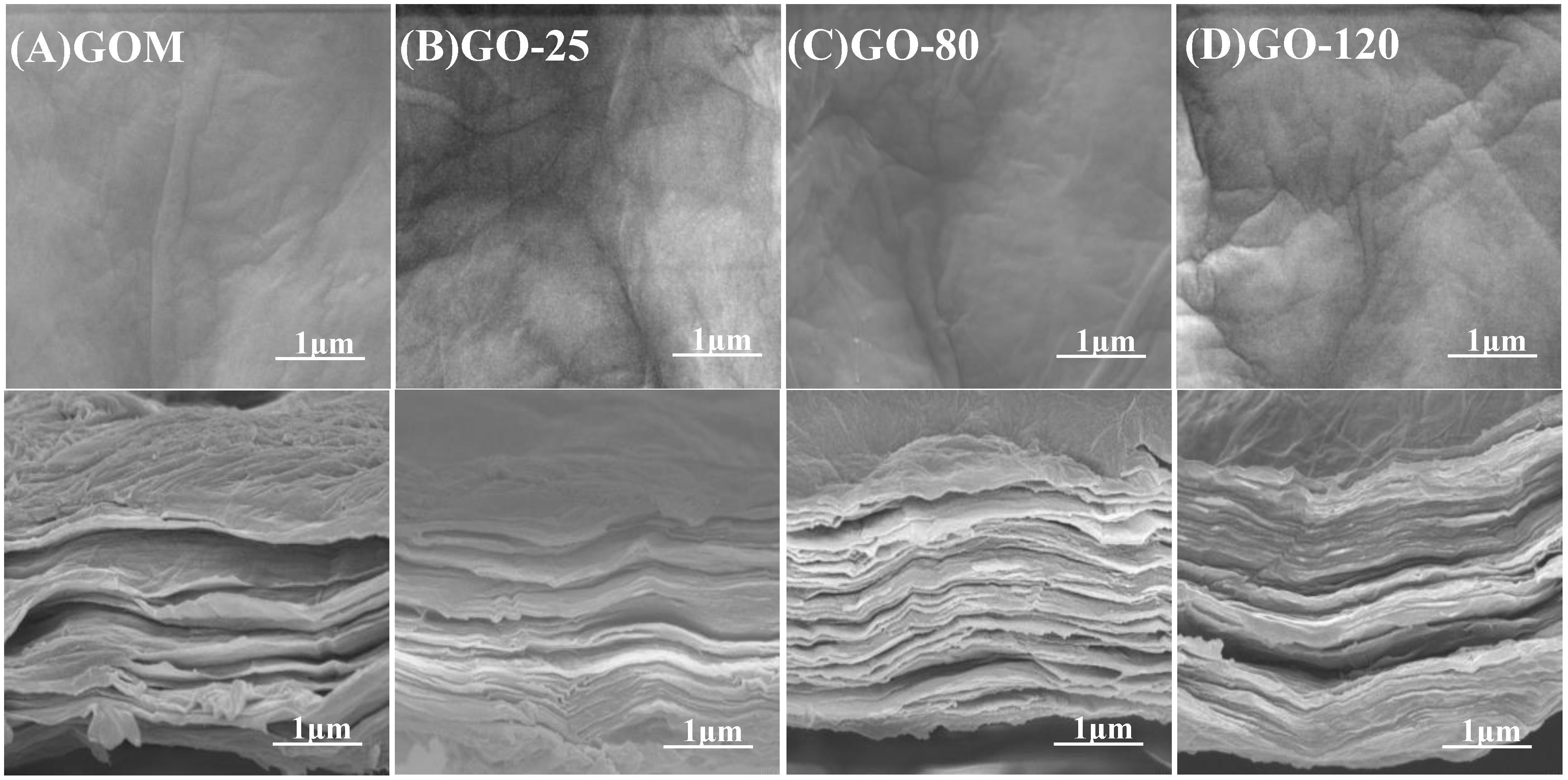
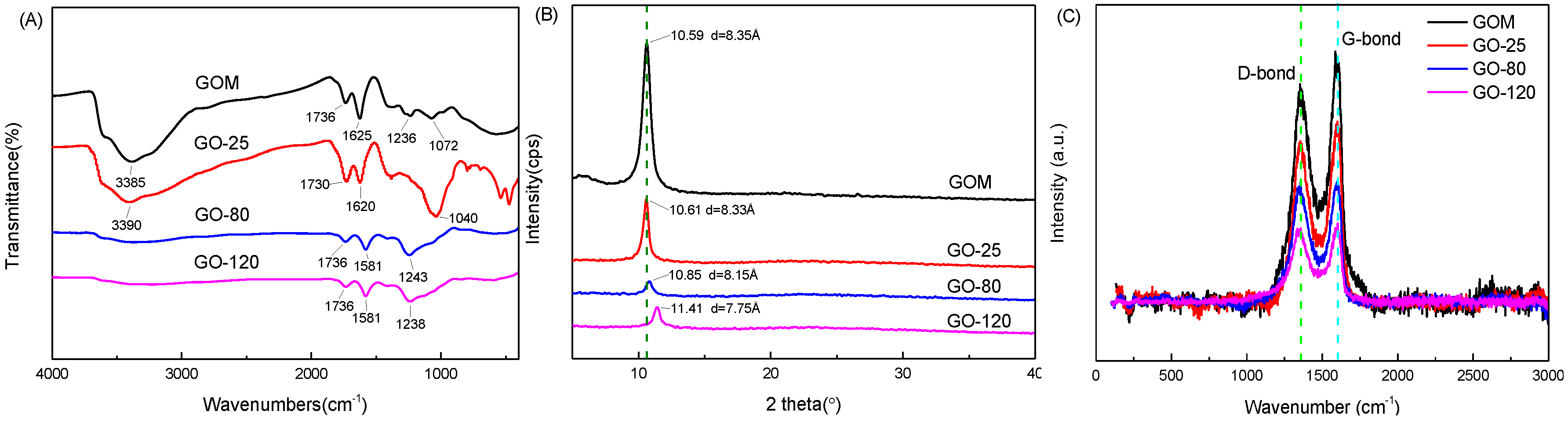
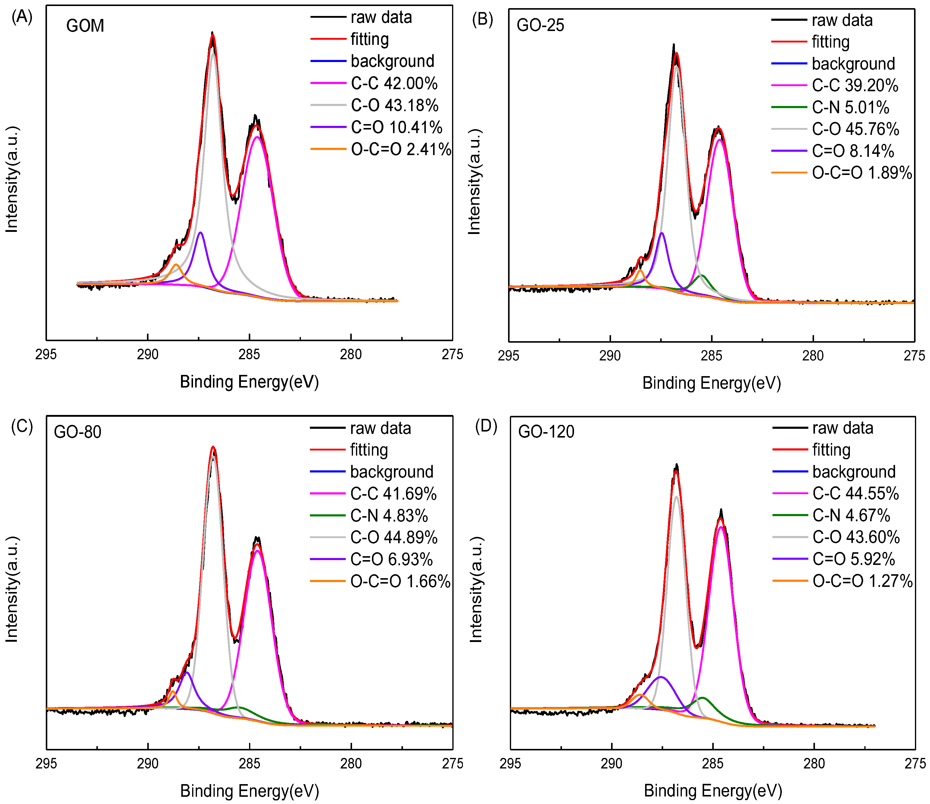
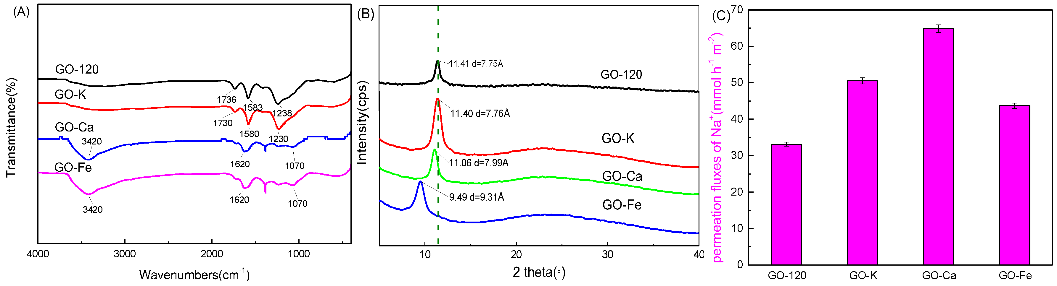
3.1. Structure Characteristics and Stability of GO Composite Membrane

The surfaces and cross sections of the GOMs were characterized by scanning electron microscopy (SEM). Figure 1A–D show the surface morphology and layer structure of untreated GOM, GO-25, GO-80, and GO-120, respectively. The membranes display wrinkled surfaces and stacked lamellar structures [19]. No obvious defects were visible on the membrane surfaces and the surface wrinkles are the same as untreated GOM. The layer structure cross-linked by PDA is more orderly than that of untreated GOM shown cross sections of Figure 1, which may be because the cross-linking of PDA and heat treating led to a small layer distance [24].
Figure 2A shows the FTIR spectra of untreated GOM, GO-25, GO-80, and GO-120. After reduction, the intensity of the peak from untreated GOM at 1236 cm−1 that originated from epoxy groups decreased and that of the peak at 1040 cm−1 from C-O-C groups increased, which may have been caused by the ring-opening reaction of the epoxy groups during reduction. A new peak appeared at 1581 cm−1, which corresponded to the carbon skeletal vibration of the graphene sheets. The intensity of the peak at 1736 cm−1 ascribed to C=O bonds decreased, and those at 3385 cm−1 from OH and 1072 cm−1 from C-O disappeared, which indicated that the corresponding groups of GO had been reduced during heat treatment. The observed behavior is similar to the results reported in the literature [24].
Figure 2B shows the X-ray diffraction (XRD) patterns of untreated GOM, GO-25, GO-80, and GO-120. Untreated GOM, GO-25, GO-80, and GO-120 displayed diffraction signals at 2θ of 10.59°, 10.61°, 10.85°, and 11.41°, respectively. From these peaks, we calculated the interlayer spacing (d) of the GOMs using the Bragg equation [25], which gave d values of 8.35, 8.33, 8.15, and 7.75 Å for untreated GOM, GO-25, GO-80, and GO-120, respectively. The d-spacing of the GO film (8.35 Å) was similar to previously reported values [17,19,26,27]. With increasing treatment temperature, the layer spacing of the GOMs gradually decreased. As the treatment temperature rose, some of the oxygen-containing groups in GO fell off to form rGO. The higher the treatment temperature, the greater the degree of reduction of the GOM. Thus, the degree of deoxygenation (i.e., reduction) strongly affected the average d-spacing of the GOM, and was related to its hydrophilicity. Figure 2B also showed that the diffraction peaks after heat treatment were considerably wider and weaker than that of the original GO, which may have been caused by the partial destruction of the crystal structure during heat treatment [8,22].
The zeta potentials of GO, GOs-80, and GOs-120 solutions (GOs-80, and GOs-120 were GO solution heated in 80, and 120 °C for 1 h under stirring, respectively) were measured, as shown in Figure S2. The GO, GOs-80, and GOs-120 solutions remained electronegative within the pH range of 2–10 [28,29,30]. With increasing pH, the H+ concentration in solution decreases and the surface charge became more and more negative [31]. The surface potential of the GOs was related to the treatment temperature, and the potential of the GOs was GO < GOs-80 < GOs-120. We propose that the surface potential decreased because of the decrease in the content of oxygen-containing groups as the treatment temperature was raised [30].
Raman spectroscopy was used to characterize the structure of the GOM, as shown in Figure 2C. The G band at around 1580 cm−1 and D band at around 1350 cm−1 were the main features in the Raman spectrum of GO, which were assigned to the sp2 hybridization of the graphitized structure and local lattice defects, respectively. The intensity ratio of the D to the G peak (ID/IG) is an important parameter to characterize the defect density in graphene. The calculated ID/IG values of the untreated GOM, GO-25, GO-80, and GO-120 were 0.88, 0.9, 0.95, and 0.97, respectively. ID/IG increased with treatment temperature, indicating that the content of lattice defects increased, which should affect the infiltration of cations [32].
X-ray photoelectron spectroscopy (XPS) analysis of the untreated GOM, GO-25, GO-80, and GO-120 is presented in Figure S3 and C1s spectra are displayed in Figure 3. Figure S3 showed that GO-25, GO-80, and GO-120 exhibited three peaks, whereas the untreated GOM only exhibited two peaks. This demonstrated that PDA was successfully cross-linked with GO during heat treatment at all temperatures. The elemental analysis confirmed that GO-25, GO-80, and GO-120 contained nitrogen, as listed in Table S1.
Figure 3A reveals that there were four peaks in the C1s spectrum of the untreated GOM; namely, C-C at 284.6 eV with a content of 42.00%, C-O with a peak area of 43.18% at 286.8 eV, C=O with a content of 10.41% at 287.3 eV, and O-C=O at 288.5 eV with a content of 2.41% [18]. The C1s spectra of GO-25, GO-80, and GO-120 are provided in Figure 3B–D, respectively. Five peaks were observed at binding energies of 284.6, 285.5, 286.8, 287.3, and 288.5 eV, which corresponded to C-C, C-N, C-O, C=O, and O-C=O groups, respectively [26]. The strength of the signals from C=O and O-C=O bonds in GO-25, GO-80, and GO-120 decreased markedly after heat treatment, which indicated that oxygen functional groups were partially removed by the thermal reaction [28]. This also demonstrated that the content of C=O bonds decreased and that of C-C bonds increased with rising treatment temperature. Moreover, nitrogen contents of approximately 1% were detected for GO-25, GO-80, and GO-120 after cross-linking with PDA measured by elemental analyzer [33] (see Table S1).
The stability of the untreated GOM, GO-25, GO-80, and GO-120 was studied by immersion of the membranes in water, ethanol, and a 1:1 water/ethanol mixture. The GOMs remained intact for 24 h in all of the solutions. During subsequent ultrasonication, the GOM broke into pieces after a few seconds, whereas GO-25, GO-80, and GO-120 remained intact for more than 5 min. Therefore, the stability of GO-25, GO-80, and GO-120 was improved after cross-linking with PDA via heat treatment. The tensile strength of the films was measured; the tensile strengths of GO-25, GO-80, and GO-120 were 5.61, 4.89, and 4.78 MPa, respectively. Thus, the composite membranes possess both good tensile strength and high stability [34].
The parameters of BET surface area, pore size and pore volume distribution were listed in Table S2. The specific surface area was 12.1633, 60.4379, and 55.3727 m2 g−1 and the pore size was 50.38802, 1.90113, and 2.15128 nm for GO-25, GO-80, and GO-120, indicating that temperature had a very significant effect on surface character. The BET surface area was big, and the pore size was small when the temperature increased. This was the same result as the XRD characterization.

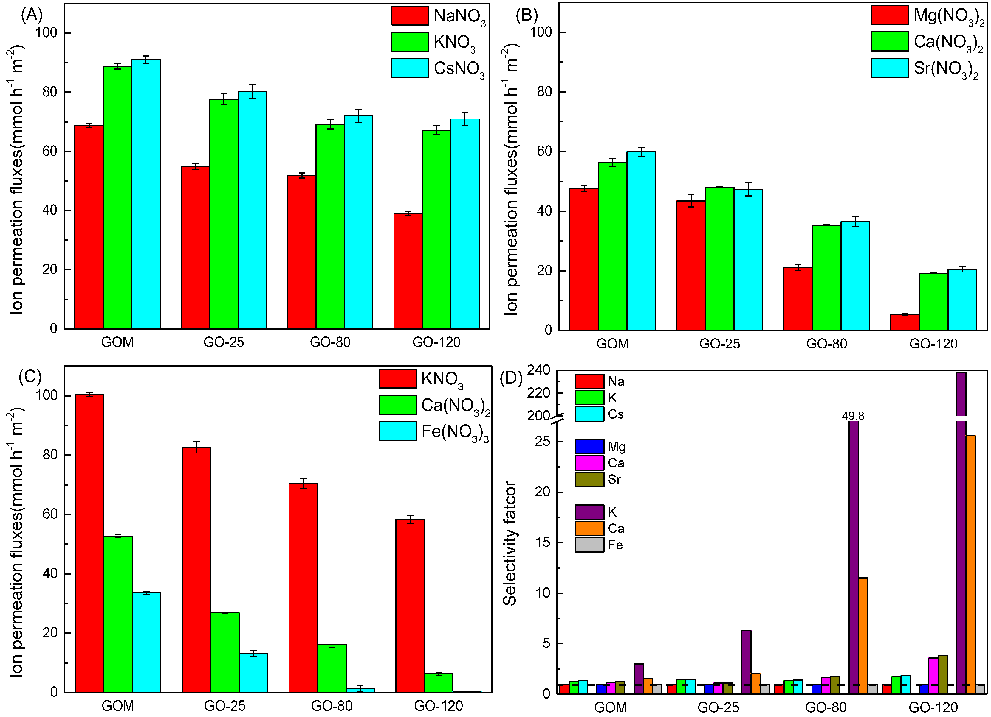
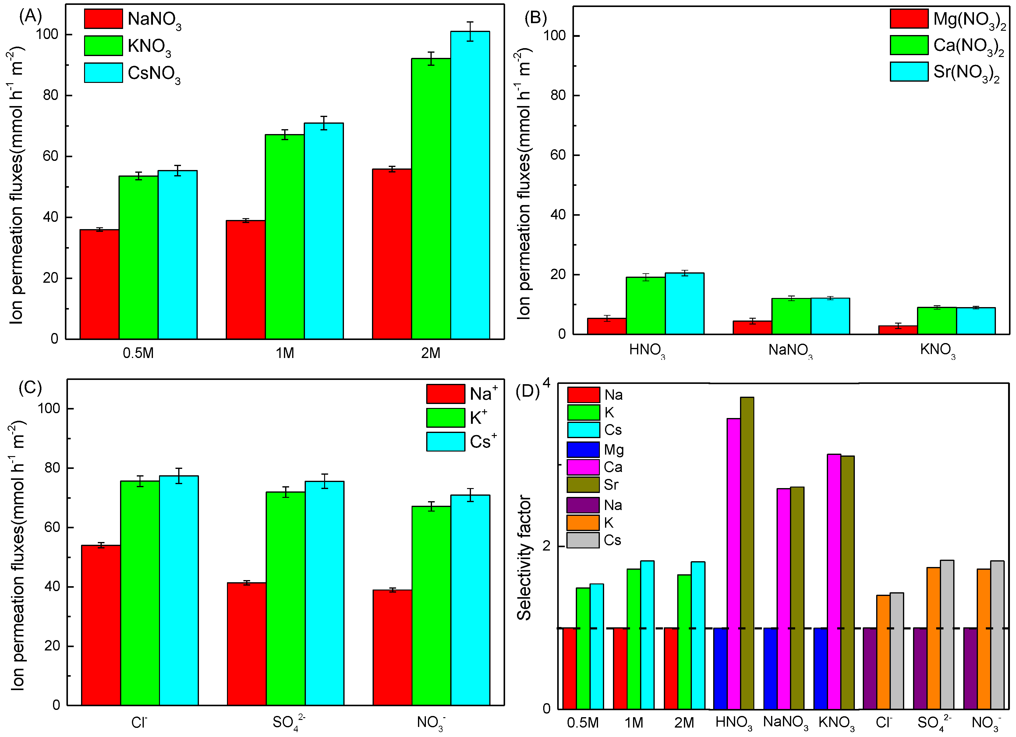
3.2. Metal Ion Permeation through the GOMs

The permeation rates of mixed salt solutions through the untreated GOM, GO-25, GO-80, and GO-120 are shown in Figure 4. A kinetic study of Na+ permeation flux through the untreated GOM, GO-25, GO-80, and GO-120 is presented in Figure S4. The Na+ permeation amount increased over time and the order of transport was untreated GOM > GO-25 > GO-80 > GO-120. Figure 4A–C illustrate that metal ions permeated through the GOMs with the order of untreated GOM > GO-25 > GO-80 > GO-120. The XRD results indicated that the d-spacing of the GOMs was untreated GOM > GO-25 > GO-80 > GO-120. Therefore, the larger the interlayer spacing, the higher the ion permeability of the GOMs [22]. The BET surface area and pore size also demonstrated that GO-25 had big pore size and small surface area to the benefit of cation permeation.
Figure 4A,B show that the permeabilities of the GOMs to alkali metals and alkaline earth metals were: Cs+ > K+ > Na+ and Sr2+ > Ca2+ > Mg2+, which were opposite to the order of the sizes of their hydrated ionic radii (Table 1). The permeability of the GOMs to monovalent alkali metal ions was greater than that to bivalent alkaline earth metal ions. Many studies have reported that cations of the same valence with a smaller hydrated ionic radius display higher permeation than those with larger hydrated ionic radius and the permeability of monovalent ions in the first main group is greater than that of bivalent ions [6,19,29]. Figure 4C shows the permeability behavior of K+, Ca2+, and Fe3+ through the untreated GOM, GO-25, GO-80, and GO-120. For all GOMs, the order of permeability was K+ > Ca2+ > Fe3+, which was opposite to the order of their hydrated ionic radii (Table 1). Lim et al. [19] proposed that the ionic permeability through a GOM was related to the interaction between GO oxygen-containing functional groups and cations in addition to the cation hydrated ionic radius. Therefore, a strong interaction between cations and GO will prevent ions from permeating through the GO layer.
Figure 4D and Table S3 show the separation factors between three types of cations in mixed solutions calculated using Equation (2), in which the smallest permeation flux was the denominator. The separation factors of cations through the GOMs were smallest for the untreated GOM and largest for GO-120. The separation factors of K/Na and Cs/Na using the GO-120 membrane were 1.72 and 1.82, respectively, and reached 3.57 and 3.83 for Ca/Mg and Sr/Mg. The separation factors of K/Fe and Ca/Fe when K+, Ca2+ and Fe3+ permeated through GO-120 were 238.20 and 25.61, respectively, which were much higher than other reported previously [6] and [19]. Overall, GO-120 displayed the best separation behavior for main group elements amongst GO-25, GO-80, and GO-120.
Figure 5A shows the permeation rates of Na+, K+ and Cs+ through GO-120 when the concentration of nitric acid in the permeate tank was 0.5, 1.0, and 2.0 mol/L. When H+ passed through GO-120, hydrogen bonds were formed between H+ and the oxygen-containing groups of GO-120, which neutralized the electronegativity of GO-120. As a result, the electrostatic attraction between GO-120 and metal ions decreased as the H+ concentration in the permeate tank increased and the permeability of the metal ions rose [36].
The penetration behavior of Mg(NO3)2, Ca(NO3)2, and Sr(NO3)2 mixed solutions through GO-120 when the driving solution in the permeate tank was HNO3, NaNO3, or KNO3 (1.0 mol/L) is shown in Figure 5B. The permeability order was Sr2+ > Ca2+ > Mg2+ when Mg(NO3)2, Ca(NO3)2, and Sr(NO3)2 were passed through GO-120, whereas the order was HNO3 > NaNO3 > KNO3 when different driving solutions were used. The permeate flux of the cations from the feed tank into permeate tank was lower when the driving solution was NaNO3 or KNO3 compared with the case when HNO3 solution was used because the ionic strength was the same in the feed and permeate tanks [37].
Figure 5C shows the infiltration behavior of Na+, K+, and Cs+ through GO-120 when anions were Cl, SO42−, and NO3 in feed tank and 1.0 mol/L HNO3 in permeate tank. The observed order of the permeability rates was chloride > sulfate > nitrate. GO is negatively charged (see Figure S2) and thus repels anions through Donnan repulsion. The GO-120 membrane strongly rejected sulfate because of its high valence state [14,30], which resulted in the low permeation of sulfate. The low permeability of nitrate arose from the same concentration of nitrate anion in the permeate and feed tanks.
Figure 5D and Table S4 present the separation factors for three mixed cations with different feed or permeate solutions through the GO-120 membrane. The separation factors of K/Na and Cs/Na were 1.49–1.81 when the nitric acid concentration was 0.5, 1.0, or 2.0 mol/L in permeate tank, whereas it was 1.40–1.83 when anions were Cl, SO42−, and NO3 in the feed solution. The nitric acid concentration and salt species had weak effects on the separation factors of K/Na and Cs/Na. When the driving solution was HNO3, NaNO3 and KNO3, the separation factors of Ca/Mg and Sr/Mg were 2.71–3.83, which indicated a high possibility of effective separation.

3.3. Metal Ion Insertion into the GO-120 Membrane

To determine the residual amount of metal ions in the membrane and their influence on cation permeability through the membrane, the sorption of K+, Ca2+, and Fe3+ on GO-120 and the subsequent permeability of Na+ were studied. Figure S5 shows the XPS analysis of GO-K, GO-Ca. and GO-Fe. K+, Ca2+, and Fe3+ were adsorbed on GO-120 with adsorption contents of 0.03%, 0.34%, and 0.50%, respectively. These results show that Fe3+ was adsorbed the most readily whereas K+ was the most difficult for GO-120 to adsorb. From these results, we can infer that the cations with a high valence state and small radius are easily adsorbed [37].
GO-120, GO-K, GO-Ca, and GO-Fe were characterized by FTIR spectroscopy (Figure 6A). The characteristic peaks of GO-K were nearly the same as those of GO-120. However, the peaks at 1734 cm−1 (originating from C=O) of GO-Ca and GO-Fe became weak compared with that for GO-120, which reflected the reaction between –COOH and metal ions, and the peak at 1230 cm−1 from epoxy groups disappeared, which may have been caused by the ring-opening reaction of epoxy groups. Because GO-120 contained a large number of epoxy functional groups, GO coordinating with metal ions may lead to the opening of the epoxy C=O groups, which produced C-O bonds [37]; therefore, the intensity of the C-O vibration peak at 1070 cm−1 was obviously enhanced after ion adsorption [38]. In addition, a peak at 3420 cm−1 ascribed to the OH stretching vibration peak of water combined with metal ions was observed for GO-K, GO-Ca, and GO-Fe.
GO-120, GO-K, GO-Ca, and GO-Fe were also characterized by XRD; the results are shown in Figure 6B. In the XRD patterns, peaks appeared at 11.41°, 11.40°, 11.06°, and 9.49° for GO-120, GO-K, GO-Ca, and GO-Fe, respectively, giving layer spacings of 7.75, 7.76, 7.99, and 9.31 Å, respectively. The interlayer spacings of GO-K, GO-Ca, and GO-Fe were greater than that of GO-120. This is because the cations in the GO layers increased the distance between GO layers [14,17,38]. GO-Fe had the largest d-spacing, which is because Fe3+ has the largest hydrated ionic radius among K+, Ca2+, and Fe3+. Cho et al. [14] studied the insertion of alkali metal ions into GO layers and found that the GO layer spacing increased with the hydrated ionic radius of the ions inserted in the GO layers. Yu and colleagues proposed that there is a strong interaction between the hydrated metal ions and GO and the hydrated ions strongly adsorb on the aromatic rings of GO, which controls the spacing between GO layers [38]. Hydrated ions help to support the GO layers and larger ions result in a larger interlayer spacing.
Figure 6C shows the Na+ permeability of GO-120, GO-K, GO-Ca, and GO-Fe. The order of Na+ permeation flux was GO-120 < GO-Fe < GO-K < GO-Ca. GO-K has almost the same layer spacing as that of GO-120, but the permeation rate of GO-K was higher than that of GO-120. This indicates that K+ in the GO interlayer partially neutralized the electronegativity of GO and facilitated Na+ permeation. GO-Fe, which adsorbed approximately 0.50% Fe3+ on the GO layers, exhibited a certain repulsive force to Na+ after neutralizing the electronegativity of the GOM. Therefore, the electrostatic interaction between GO and metal ions could affect the cation permeability of GOMs. This finding was consistent with the low permeate flux of high-valence cations caused by electrostatic repulsion [6,19].

4. Conclusions

Stable GOMs with different layer spacing were fabricated by thermal treatment. The permeate fluxes of alkali and alkaline earth metal ions through the membranes increased with decreasing hydration radius of the cations and increasing layer spacing of the membrane. A high cation valence led to low permeation because of electrostatic repulsion. GO-120 had a narrow d-spacing and high separation factors for K/Na, Cs/Na; Ca/Mg, Sr/Mg; and K/Fe, Ca/Fe compared with those of the other GOMs. Cations can insert into the GO layers as they pass through the GOM, enlarging the d-spacing and neutralizing the electronegativity of the GOM. Such behavior is beneficial for cation transport through GOMs, although an excess of cations between the GO layers can repel other cations out of the GOM through electrostatic repulsion.

Supplementary Materials

The following are available online at https://0-www-mdpi-com.brum.beds.ac.uk/2073-4352/9/4/214/s1, Figure S1: The photo of the home-made filtration device. Figure S2: Zeta potential of GO, GOs-80, and GOs-120. Figure S3: Full spectrum spectra of GOM, GO-25, GO-80, and GO-120. Table S2. The surface character of GO-25, GO-80, and GO-120. Figure S4: Effect of time to Na+ permeation fluxes through GOM, GO-25, GO-80, and GO-120 membrane. 0.02 mol/L NaNO3 solution in feed tank, 1.0 mol/L HNO3 in permeate tank. Figure S5: XPS survey spectra of (A) GO-K, (B) GO-Ca, (C) GO-Fe. Table S1: Element composition of GO-25, GO-80, and GO-120. Table S2: The surface character of GO-25, GO-80, and GO-120. Table S3: Separation factor of GOM, GO-25, GO-80, and GO-120 membrane to mixture ions ([M] = 0.02 mol/L). Table S4: Separation factor of GO-120 membrane to mixture ions ([M] = 0.02 mol/L).

Author Contributions

B.H. and Q.M. carried out the membrane prepared and permeate experiments; H.W. and L.L. measured and analyzed the data; T.L. and W.T. designed diagram and analyzed membrane properties; P.H. and L.Q. conceived and wrote the paper; Z.L. and W.S. gave supervision and advice on the experiments and revised the paper.

Funding

Financial support from the National Science Foundation of China (Grants 21571088, 21876073)

Acknowledgments

We thank Natasha Lundin, PhD, from Liwen Bianji, Edanz Editing China (www.liwenbianji.cn/ac), for editing the English text of a draft of this manuscript.

Conflicts of Interest

The authors declare no conflict of interest.

References

  1. O’Hern, S.C.; Jang, D.; Bose, S.; Idrobo, J.C.; Song, Y.; Laoui, T.; Kong, J.; Karnik, R. Nanofiltration across Defect-Sealed Nanoporous Monolayer Graphene. Nano Lett. 2015, 15, 3254–3260. [Google Scholar] [CrossRef] [Green Version]
  2. Mi, B. Graphene oxide membranes for ionic and molecular sieving. Science 2014, 343, 740–742. [Google Scholar] [CrossRef] [PubMed]
  3. Li, Z.; Liu, Y.; Zhao, Y.; Zhang, X.; Qian, L.; Tian, L.; Bai, J.; Qi, W.; Yao, H.; Gao, B.; et al. Selective Separation of Metal Ions via Monolayer Nanoporous Graphene with Carboxyl Groups. Anal. Chem. 2016, 88, 10002–10010. [Google Scholar] [CrossRef] [PubMed]
  4. Abraham, J.; Vasu, K.S.; Williams, C.D.; Gopinadhan, K.; Su, Y.; Cherian, C.T.; Dix, J.; Prestat, E.; Haigh, S.J.; Grigorieva, I.V.; et al. Tunable sieving of ions using graphene oxide membranes. Nat. Nanotechnol. 2017, 12, 546–550. [Google Scholar] [CrossRef] [Green Version]
  5. Yang, Q.; Su, Y.; Chi, C.; Cherian, C.T.; Huang, K.; Kravets, V.G.; Wang, F.C.; Zhang, J.C.; Pratt, A.; Grigorenko, A.N.; et al. Ultrathin graphene-based membrane with precise molecular sieving and ultrafast solvent permeation. Nat. Mater. 2017, 16, 1198–1202. [Google Scholar] [CrossRef] [Green Version]
  6. Jia, Z.; Shi, W. Tailoring permeation channels of graphene oxide membranes for precise ion separation. Carbon 2016, 101, 290–295. [Google Scholar] [CrossRef]
  7. Chen, L.; Shi, G.; Shen, J.; Peng, B.; Zhang, B.; Wang, Y.; Bian, F.; Wang, J.; Li, D.; Qian, Z.; et al. Ion sieving in graphene oxide membranes via cationic control of interlayer spacing. Nature 2017, 550, 380–383. [Google Scholar] [CrossRef] [PubMed]
  8. Choi, W.; Chun, K.Y.; Kim, J.; Han, C.S. Ion transport through thermally reduced and mechanically stretched graphene oxide membrane. Carbon 2017, 114, 377–382. [Google Scholar] [CrossRef]
  9. Huang, L.; Li, Y.; Zhou, Q.; Yuan, W.; Shi, G. Graphene oxide membranes with tunable semipermeability in organic solvents. Adv. Mater. 2015, 27, 3797–3802. [Google Scholar] [CrossRef] [PubMed]
  10. Nair, R.R.; Wu, H.A.; Jayaram, P.N.; Grigorieva, I.V.; Geim, A.K. Unimpeded Permeation of Water Through Helium-Leak-Tight Graphene-Based Membranes. Science 2012, 335, 442–444. [Google Scholar] [CrossRef]
  11. Erickson, K.; Erni, R.; Lee, Z.; Alem, N.; Gannett, W.; Zettl, A. Determination of the Local Chemical Structure of Graphene Oxide and Reduced Graphene Oxide. Adv. Mater. 2010, 22, 4467–4472. [Google Scholar] [CrossRef] [PubMed]
  12. Liu, G.; Jin, W.; Xu, N. Graphene-based membranes. Chem. Soc. Rev. 2015, 44, 5016–5030. [Google Scholar] [CrossRef] [PubMed]
  13. Hung, W.S.; An, Q.F.; Guzman, M.D.; Lin, H.Y.; Huang, S.H.; Liu, W.R.; Hu, C.C.; Lee, K.R.; Lai, J.Y. Pressure-assisted self-assembly technique for fabricating composite membranes consisting of highly ordered selective laminate layers of amphiphilic graphene oxide. Carbon 2014, 68, 670–677. [Google Scholar] [CrossRef]
  14. Cho, Y.H.; Kim, H.W.; Lee, H.D.; Shin, J.E.; Yoo, B.M.; Park, H.B. Water and ion sorption, diffusion, and transport in graphene oxide membranes revisited. J. Membr. Sci. 2017, 544, 425–435. [Google Scholar] [CrossRef]
  15. Deng, H.; Sun, P.Z.; Zhang, Y.J.; Zhu, H.W. Reverse osmosis desalination of chitosan cross-linked graphene oxide/titania hybrid lamellar membranes. Nanotechnology 2016, 27, 274002. [Google Scholar] [CrossRef]
  16. Liu, H.; Wang, H.; Zhang, X. Facile Fabrication of Freestanding Ultrathin Reduced Graphene Oxide Membranes for Water Purification. Adv. Mater. 2015, 27, 249–254. [Google Scholar] [CrossRef]
  17. Jia, Z.; Wang, Y. Covalently crosslinked graphene oxide membranes by esterification reactions for ions separation. J. Mater. Chem. A 2015, 3, 4405–4412. [Google Scholar] [CrossRef]
  18. Jin, L.; Wang, Z.; Zheng, S.; Mi, B. Polyamide-crosslinked Graphene Oxide Membrane for Forward Osmosis. J. Membr. Sci. 2018, 545, 11–18. [Google Scholar] [CrossRef]
  19. Lim, M.Y.; Choi, Y.S.; Kim, J.; Kim, K.; Shin, H.; Kim, J.J.; Shin, D.M.; Lee, J.C. Cross-linked graphene oxide membrane having high ion selectivity and antibacterial activity prepared using tannic acid-functionalized graphene oxide and polyethyleneimine. J. Membr. Sci. 2017, 521, 1–9. [Google Scholar] [CrossRef]
  20. Hu, M.; Mi, B. Enabling Graphene Oxide Nanosheets as Water Separation Membranes. Environ. Sci. Technol. 2013, 47, 3715–3723. [Google Scholar] [CrossRef]
  21. Liu, Z.; Wu, W.; Liu, Y.; Qin, C.; Meng, M.; Jiang, Y.; Qiu, J.; Peng, J. A mussel inspired highly stable graphene oxide membrane for efficient oil-in-water emulsions separation. Sep. Purif. Technol. 2018, 199, 37–46. [Google Scholar] [CrossRef]
  22. Zhan, Y.; Wan, X.; He, S.; Yang, Q.; He, Y. Design of durable and efficient poly(arylene ether nitrile)/bioinspired polydopamine coated graphene oxide nanofibrous composite membrane for anionic dyes separation. Chem. Eng. J. 2018, 333, 132–145. [Google Scholar] [CrossRef]
  23. Marcano, D.C.; Kosynkin, D.V.; Berlin, J.M.; Sinitskii, A.; Sun, Z.; Slesarev, A.; Alemany, L.; Lu, W.; Tour, J. Improved synthesis of graphene oxide. ACS Nano 2010, 4, 4806–4814. [Google Scholar] [CrossRef] [PubMed]
  24. Wang, J.; Huang, T.; Zhang, L.; Yu, Q.J.; Hou, L. Dopamine crosslinked graphene oxide Membrane for simultaneous removal of organic pollutants and trace heavy metals from aqueous solution. Environ. Technol. 2018, 39, 3055–3065. [Google Scholar] [CrossRef]
  25. Pope, C.G. X-ray Diffraction and the Bragg Equation. J. Chem. Educ. 1997, 74, 129. [Google Scholar] [CrossRef]
  26. Hung, W.S.; Tsou, C.H.; Guzman, M.D.; An, Q.F.; Liu, Y.L.; Zhang, Y.M.; Hu, C.C.; Lee, K.R.; Lai, J.Y. Cross-linking with diamine monomers to prepare composite graphene oxide-framework membranes with varying d-spacing. Chem. Mater. 2014, 26, 2983–2990. [Google Scholar] [CrossRef]
  27. Ma, F.; Li, Z.; Zhao, H.; Geng, Y.; Zhou, W.; Li, Q.; Zhang, L. Potential application of graphene oxide membranes for removal of Cs(I) and Sr(II) from high level-liquid waste. Sep. Purif. Technol. 2017, 188, 523–529. [Google Scholar] [CrossRef]
  28. Hu, M.; Mi, B. Layer-by-layer assembly of graphene oxide membranes via electrostatic interaction. J. Membr. Sci. 2014, 469, 80–87. [Google Scholar] [CrossRef]
  29. Hu, M.; Zheng, S.; Mi, B. Organic fouling of graphene oxide membranes and its implications for membrane fouling control in engineered osmosis. Environ. Sci. Technol. 2016, 50, 685–693. [Google Scholar] [CrossRef] [PubMed]
  30. Oh, Y.; Armstrong, D.L.; Finnerty, C.; Zheng, S.; Hu, M.A. Torrents, B. Mi, Understanding the pH-responsive behavior of graphene oxide membrane in removing ions and organic micropollulants. J. Membr. Sci. 2017, 541, 235–243. [Google Scholar] [CrossRef]
  31. Baskoro, F.; Wong, C.B.; Kumar, S.R.; Chang, C.W.; Chen, C.H.; Chen, D.W.; Lue, S.J. Graphene oxide-cation interaction: Inter-layer spacing and zeta potential changes in response to various salt solutions. J. Membr. Sci. 2018, 554, 253–263. [Google Scholar] [CrossRef]
  32. Wu, J.X.; Xu, H.; Zhang, J. The application of Raman spectroscopy in the structural characterization of graphene. J. Chem. China 2014, 3, 301–308. [Google Scholar]
  33. Zhang, P.; Gong, J.L.; Zeng, G.M.; Deng, C.H.; Yang, H.C.; Liu, H.Y.; Huan, S.Y. Cross-linking to prepare composite graphene oxide-framework membranes with high-flux for dyes and heavy metal ions removal. Chem. Eng. J. 2017, 322, 657–666. [Google Scholar] [CrossRef]
  34. Fahmi, M.Z.; Wathoniyyah, M.; Khasanah, M.; Rahardjo, Y.; Wafiroh, S. Incorporation of graphene oxide in polyethersulfone mixed matrix membranes to enhance hemodialysis membrane performance. RSC Adv. 2018, 8, 931–937. [Google Scholar] [CrossRef] [Green Version]
  35. Nightingale, E.R., Jr. Phenomenological theory of ion solvation. Effective radiiof hydrated ions. J. Phys. Chem. 1959, 63, 1381–1387. [Google Scholar] [CrossRef]
  36. Wang, L.; Guo, X.; Cao, K.; Li, B.; Li, Y. Effective charge-discriminated group separation of metal ions under highly acidic conditions using nanodiamond-pillared graphene oxide membrane. J Mater. Chem. A 2017, 5, 8051–8061. [Google Scholar] [CrossRef]
  37. Liu, T.; Yang, B.; Graham, N.; Yu, W.; Sun, K. Trivalent metal cation cross-linked graphene oxide membranes for NOM removal in water treatment. J. Membr. Sci. 2017, 542, 31–40. [Google Scholar] [CrossRef]
  38. Yu, W.; Yet Yu, T.; Graham, N. Development of a stable cation modified graphene oxide membrane for water treatment. 2D Mater. 2017, 4, 045006. [Google Scholar] [CrossRef] [Green Version]
Figure 1. SEM surface and cross-section images of (A) GOM, (B) GO-25, (C) GO-80, (D) GO-120.
Crystals 09 00214 g001
Figure 2. (A) FTIR spectra of GOM, GO-25, GO-80, GO-120, (B) XRD patterns of GOM, GO-25, GO-80, GO-120 and (C) Raman spectra of GOM, GO-25, GO-80, GO-120.
Crystals 09 00214 g002
Figure 3. XPS survey spectra of (A) GOM, (B) GO-25, (C) GO-80, (D) GO-120.
Crystals 09 00214 g003
Figure 4. Ion-penetration flux (AC) through GOM, GO-25, GO-80, GO-120 membrane and separation factor of cations (D) through GOM, GO-25, GO-80, GO-120 membrane. (A) NaNO3, KNO3, CsNO3 mixed solution in feed tank, (B) Mg(NO3)2, Ca(NO3)2, Sr(NO3)2 mixed solution in feed tank and (C) KNO3, Ca(NO3)2, Fe(NO3)3 mixed solution in feed tank; and 1.0 mol/L HNO3 in permeate tank in A, B, and C; [M] = 0.02 mol/L, t = 12 h.
Crystals 09 00214 g004
Figure 5. Effect of nitric acid concentration (A) and species of the driving solution in permeate tank (B); Effect of salts species in feed tank (C); and separation factor of mixed ions (D). (A) NaNO3, KNO3 and CsNO3 mixed solution in feed tank, 0.5, 1.0, or 2.0 mol/L HNO3 in permeate tank; (B) Mg(NO3)2, Ca(NO3)2 and Sr(NO3)2 in feed tank, 1.0 mol/L HNO3, NaNO3 or KNO3 in permeate tank (C) chloride, sulfate and nitrate salt of Na, K, Cs in feed tank, 1.0 mol/L HNO3 in permeate tank; [M] = 0.02 mol/L, t = 12 h.
Crystals 09 00214 g005
Figure 6. FTIR spectra (A) and XRD patterns (B) of GO-120, GO-K, GO-Ca, GO-Fe; Permeability of Na+ through GO-120, GO-K, GO-Ca, and GO-Fe (C). (C) 0.02 mol/L NaNO3 solution in feed tank, 1.0 mol/L HNO3 in permeate tank; t = 12 h.
Crystals 09 00214 g006
Table 1. Radii of ions in crystal and hydrated states [35].
IonsIons Radii in Crystal(Å)Hydrated Ions Radii(Å)
Na+0.953.58
K+1.333.31
Cs+1.693.29
Mg2+0.654.28
Ca2+0.994.12
Sr2+1.134.12
Fe3+0.754.28

