Electro-Optical Effects of a Color Polymer-Dispersed Liquid Crystal Device by Micro-Encapsulation with a Pigment-Doped Shell


1
Smart Display Lab, Department of Electronic Engineering, Shanghai Jiao Tong University, Shanghai 200240, China
2
Division of Electronic and Display Engineering, Hoseo University, Asan, Chungnam 336-795, South Korea
*
Author to whom correspondence should be addressed.
Crystals 2019, 9(7), 364; https://0-doi-org.brum.beds.ac.uk/10.3390/cryst9070364
Submission received: 25 June 2019
/
Revised: 10 July 2019
/
Accepted: 11 July 2019
/
Published: 17 July 2019
(This article belongs to the Special Issue Patterned-Liquid-Crystal for Novel Displays)
Abstract
:Polymer-dispersed liquid crystals (PDLCs) refer to nematic liquid crystals, which are embedded in a polymer matrix. A conventional PDLC device is fabricated by phase separation. However, this method leads to non-uniform electro-optical characteristics of the device due to the non-uniform size distribution of the liquid crystal droplets. Moreover, the PDLC device is switched between the transparent state and the scattering state so that a full color scheme is intrinsically impossible without a color filter. In this paper, a fabrication method for a color PDLC device with uniform size and shape for liquid crystal droplets is proposed. Droplets of a fairly uniform size in large quantities can be obtained by means of membrane emulsification. Microcapsules are fabricated by complex coacervation with gelatin and gum arabic. By adding red, green, and blue pigments, color microcapsules are obtained. The electro-optical effects of the fabricated color PDLC devices are also demonstrated. The driving voltage of the device is 90 V, and the switching time is 8.3 ms. In the turn-on state, the measured hazes of red, green, and blue PDLC devices are 16.89%, 15.82%, and 18.55%, respectively, while in the turn-off state, the measured hazes of those devices are 65.21%, 67.32%, and 70.76%, respectively.
1. Introduction
Polymer-dispersed liquid crystals (PDLCs) refer to nematic liquid crystals, which are embedded in a polymer matrix [1]. Unlike conventional liquid crystal devices [2,3,4,5], which rely on birefringence, a PDLC device exploits the light scattering effects. The typical PDLC device can switch between a transparent state and a light scattering state by the electric field. It also has been used in a variety of optical devices such as switchable windows [6], shutters [7], gratings [8], etc. Therefore, PDLCs can be operated without a polarizer, thus reducing the loss of light. Fergason [9] proposed a micro-encapsulation method to form liquid crystal droplets within the polymer, and later West [10] investigated the phase separation behavior of mixtures of liquid crystal and polymer. This method can be used to separate the liquid crystal from the polymer solution via heat or ultraviolet (UV) light. However, with this method, it is difficult to control the size of the droplets, causing droplets of various sizes to be formed. This leads to non-uniform electro-optical characteristics of a device. Therefore, a means of creating liquid crystal droplets with a uniform size and shape is required.
Another big challenge regarding PDLC devices is the realization of full color. Conventionally, a color PDLC can be achieved by adopting a color filter or a guest–host mode with the addition of dichroic dyes [11,12]. However, when using a color filter, the fabrication process time and cost will substantially increase. In the guest–host mode, the color shift is caused by the anisotropic properties of the dichroic dye. Moreover, this type of device is short-lived, because the dichroic dye is vulnerable to ultraviolet light.
To address both the non-uniform size distribution and the full color display, we propose a color PDLC device, which is characterized by a colored core–shell structure. The fabrication process of color PDLCs with a core–shell structure of uniform size is investigated. The electro-optical properties are also demonstrated in terms of the voltage–transmittance curve, response time, and spectroscopic properties.
2. Materials and Methods
2.1. Formation of Liquid Crystal Droplets by Membrane Emulsification
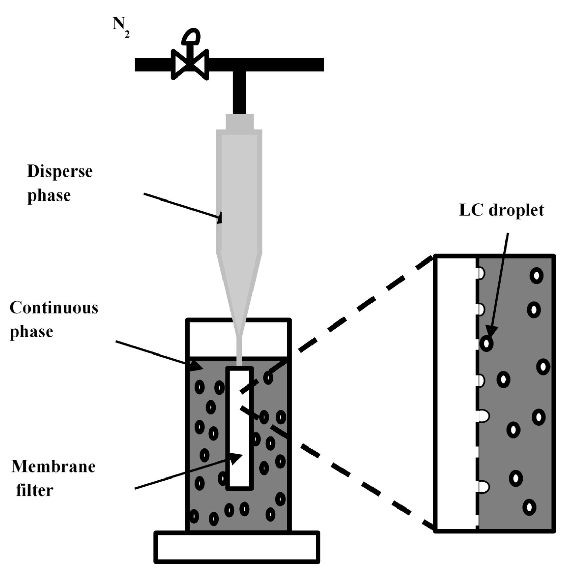
Membrane emulsification is an emulsification technique, for example, the Shirasu-porous-glass membrane emulsification method to make monodispersed emulsions developed by Nakashima et al. [13]. It is suitable for the fabrication of all types of droplets, including oil in water emulsion and water in oil emulsion. Also, membrane emulsification can form small-sized and uniform droplets. The schematic diagram of the droplet-forming process is depicted in Figure 1. The dispersed phase escapes through the porous membrane filter into the moving continuous phase. At the surface of membrane filter, the dispersed droplets, which pass though the pore of the filter, will be detached by the shear stress in the continuous phase. In this way, droplet size can be effectively controlled by the shear stress.
The surfactant (sodium dodecyl sulfate, C12H25SO4Na) doped water and liquid crystal (BHR71200-100, Linktecs Co., Ltd., Korea) are used as the continuous phase and dispersed phase, respectively. The continuous phase is made by mixing 200 mL of water with 1 g of SDS. The detailed specifications of the liquid crystal are listed in Table 1. The ordinary refractive index of the liquid crystal is 1.506 and its refractive index anisotropy is 0.199. The higher the refractive index anisotropy, the greater the scattering of light will be.
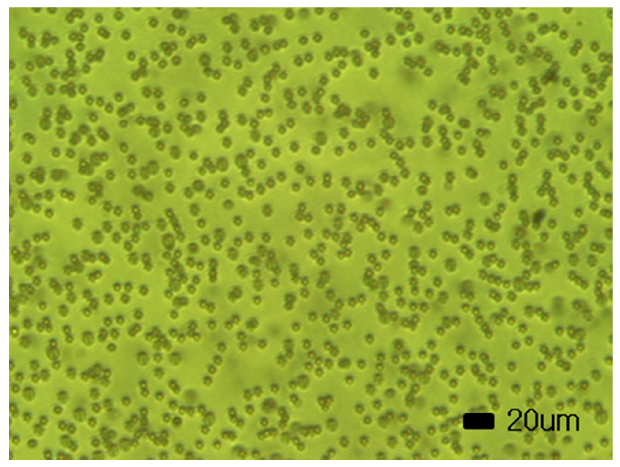
The liquid crystals are injected into the emulsification device with a membrane filter. Nitrogen gas is injected so that the liquid crystals could emerge from the membrane filter. At that time, the continuous phase is stirred at a constant velocity to obtain uniform-sized droplets. In our experiment, using the membrane filter with a pore size of 1.1 µm, liquid crystal droplets with a diameter of about 4 µm are fabricated. Figure 2 shows the fabricated liquid crystal droplets using a membrane filter with a pore size of 1.1 µm. The pore size of the membrane filter and the stirring velocity are important parameters, by which the size of the droplet could be determined. Smaller liquid crystal droplets can be obtained by using a membrane filter with a small pore size and a fast stirring velocity. When the pore size is 1.0 µm, the variation coefficient of the emulsion droplets is 14.4% and that of the fabricated polymer particles is 16.5% [14].
2.2. Pigment-Doped Color Microcapsule
Complex coacervation was first investigated by forming coacervate droplets using a system of gelatin and gum arabic [15]. It is mainly used for micro-encapsulation and is based on the interaction among oppositely charged polymers. The interaction causes a phase separation into two liquid colloids to form insoluble complexes known as a coacervate phase. The coacervate phase is more viscous and concentrated than the initial solution [16].
Gelatin is used as the shell material. It is a water-soluble protein with good film-forming ability, which finds applications in the food and biotechnology fields. There are two types of gelatin depending on the material and manufacturing method. Gelatin has an isoelectric point that is the pH, at which the total charge of the molecular surface is zero. Based on the isoelectric point, it is a positive ion in an acid and negative ion in the alkaline. Therefore, the condition of the pH is an important parameter with regard to the complex coacervation. The micro-encapsulation process of liquid crystals is carried out by means of the complex coacervation of gelatin and gum arabic as a negative-ion colloid.
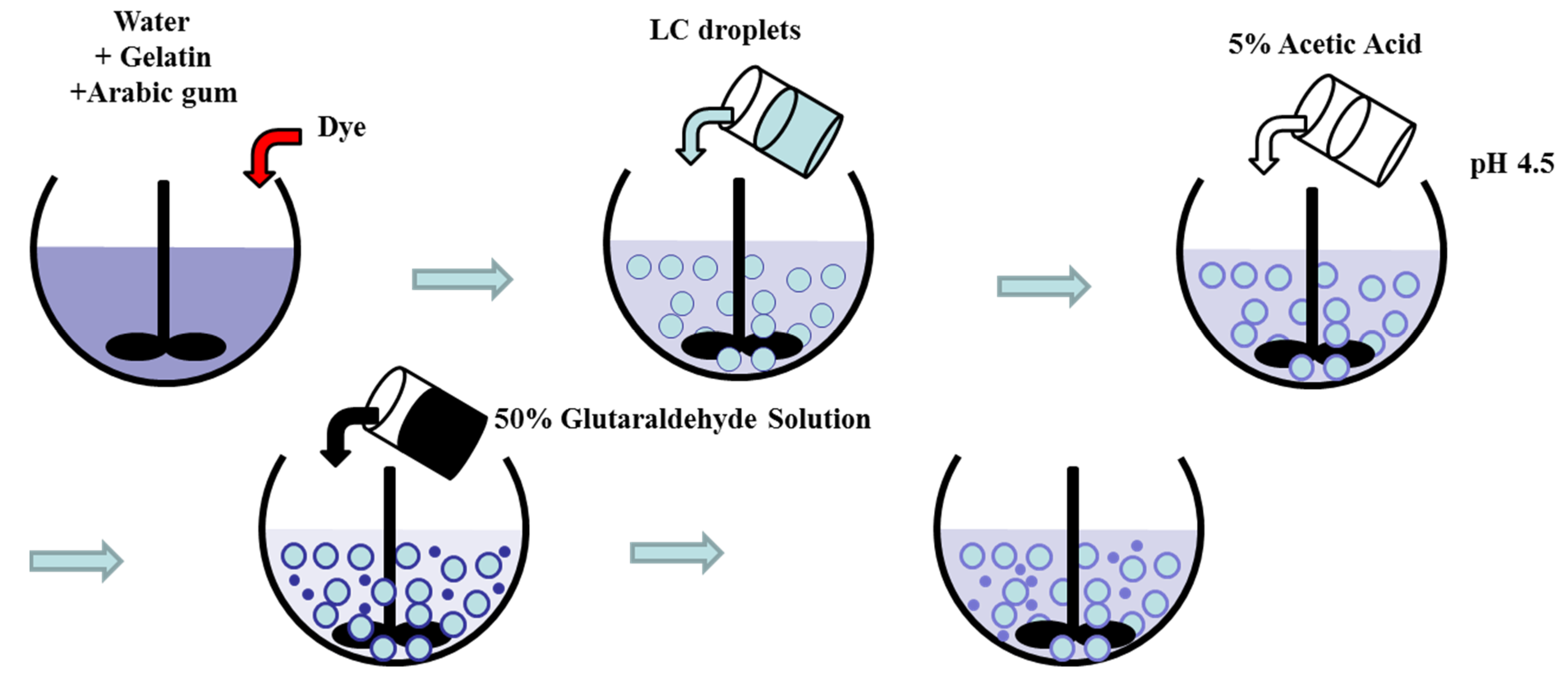
Figure 3 shows the preparation process of the core–shell structured liquid crystal microcapsule. First, a 5 wt% gelatin aqueous solution and a 5 wt% gum arabic aqueous solution are prepared for 1 h at 40 °C. After the dissolution of gelatin and gum arabic, the red, green, and blue pigments are mixed, and then the dispersed liquid crystal droplets are added [17]. To adjust the pH, acetic acid is added until pH 4.5 is reached, according to a pH meter. As time passes, the liquid crystal droplets form into a mass. Therefore, by adding deionized water after the adjusting pH, the concentration of the mixture decreases. For gelation of the mixture, the temperature is kept at 4 °C, and then glutaraldehyde is added and the temperature is maintained at 4 °C. The mixture is then stirred for 24 h. Then, the microcapsules obtained from the above process are rinsed.
2.3. Fabrication Process of the Color PDLC Device
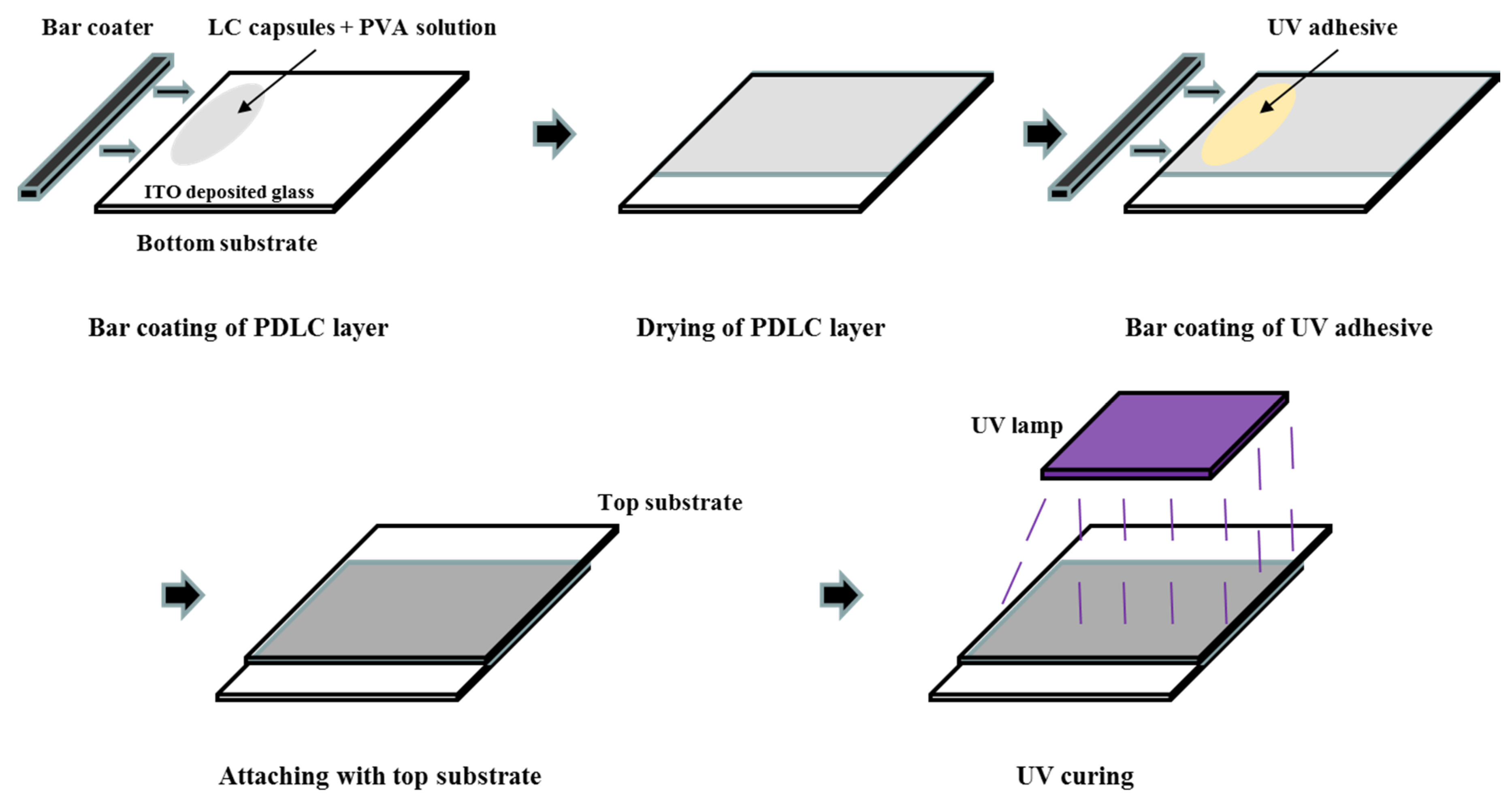
Using the prepared microcapsules, the PDLC device is fabricated, as shown in Figure 4. Indium tin oxide (ITO)-deposited glass is used as the top and bottom substrates. To clean the substrate, de-ionized water, acetone, and isopropyl alcohol (IPA) are used. After the cleaning process, a coating of the mixture of the liquid crystal capsules and polyvinyl alcohol (PVA) solution is applied by a bar coater (Gist). Polyvinyl alcohol (PVA205, Curaray), which has a refractive index of 1.51, is used as the polymer binder. The coated layer is dried at the room temperature. After drying of the PDLC layer, the top substrate is bonded to the bottom substrate using a UV adhesive with a thickness of 1 µm. By curing the device with UV light, the PDLC device is fabricated.
3. Electro-Optical Effects of Color PDLCs
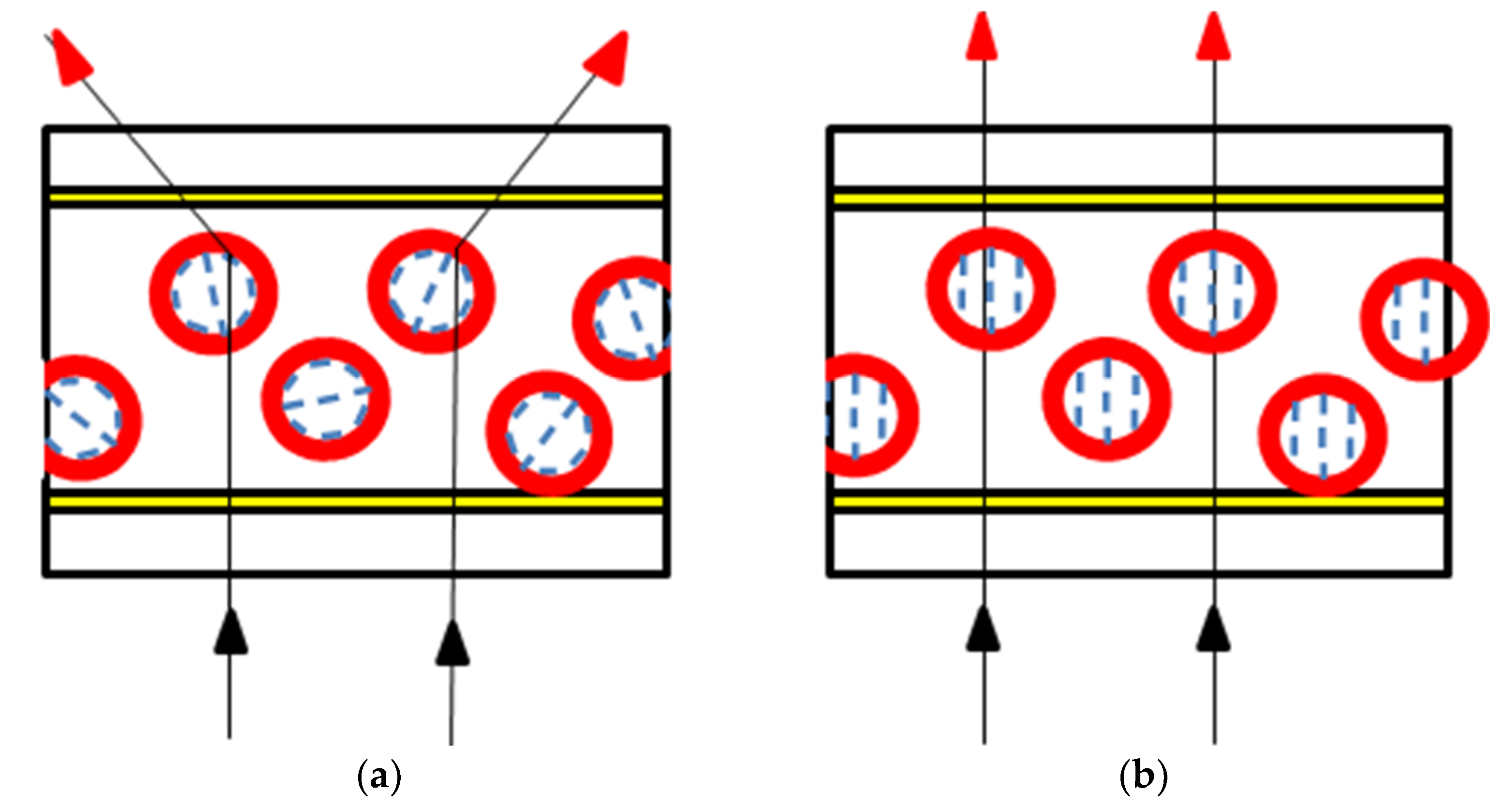
Figure 5 shows the switching behavior of color PDLCs with the core–shell structure. When no voltage is applied, the encapsulated liquid crystals with the color shell are dispersed in the polymer matrix. The liquid crystal molecules in the droplets assume a bipolar or radial configuration depending on the interaction characteristics, which causes the light scattering. By contrast, when a voltage is applied, the liquid crystal molecules are oriented in parallel to the electric field. In this state, light is transmitted by minimizing the scattering, as the ordinary refractive index of the liquid crystal and the refractive index of polymer are nearly identical.
The parameters, which affect the optical properties of the PDLC device, include the shape and size of the droplets, the density, and the refractive index. The intensity of transmitted light I is described as follows [18]:
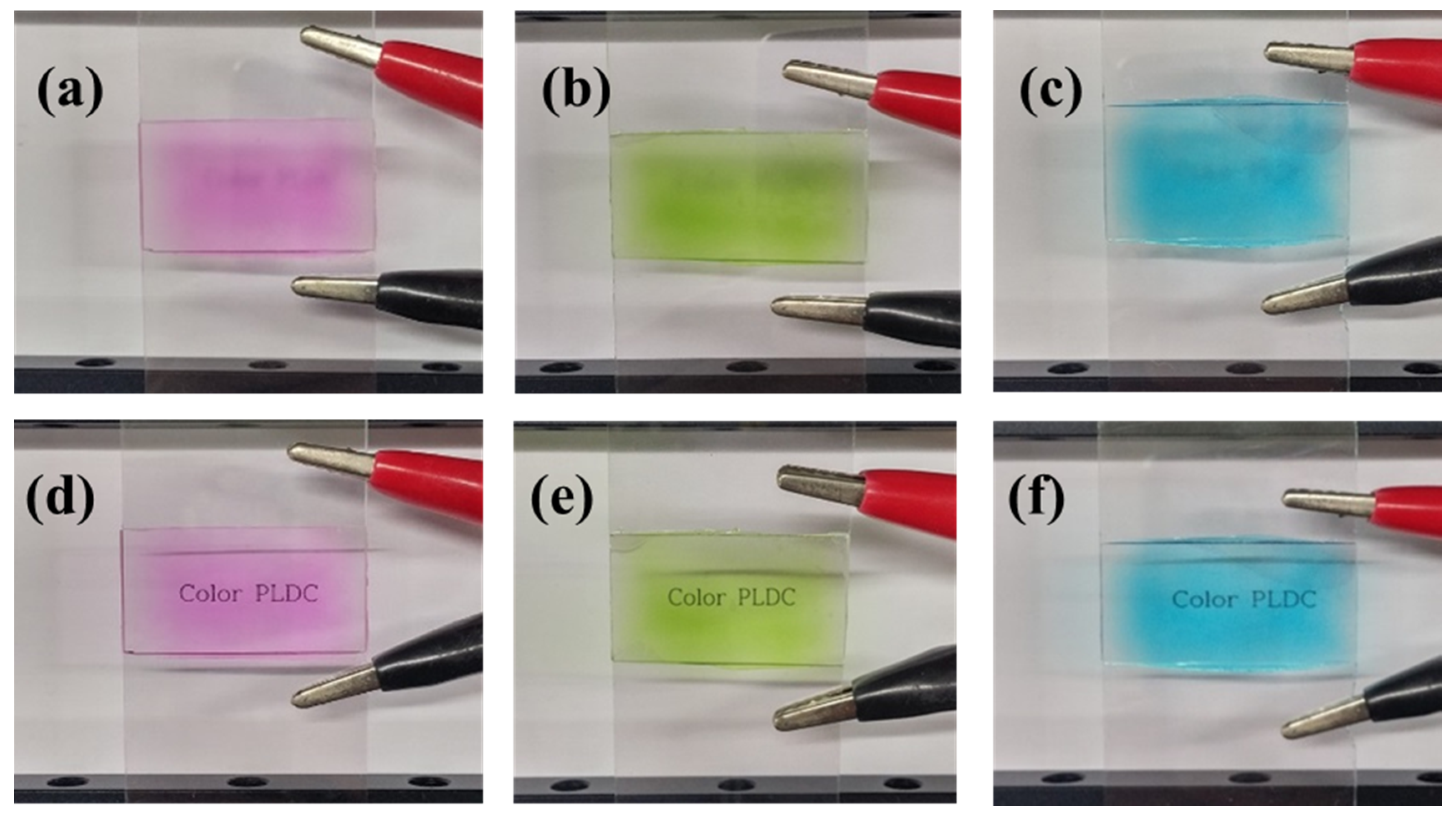
where I0 is the incidence light to the PDLC device, N is the density of the liquid crystal droplets, d is the distance, and σ is related to the orientation of the droplets. The driving voltage of the PDLC device is affected by the characteristics of liquid crystals, such as the elastic constant and the dielectric anisotropy, the size of droplets, and the cell gap of the device. A high electric field is required when the elastic constant and the dielectric anisotropy are large and small, respectively. Also, a higher electric field is required when the droplet is very small due to the increase in the anchoring energy on the surface of the droplet. Figure 6 shows the electro-optical effects of the fabricated color PDLCs, where both the scattering state (voltage off) and transparent state (voltage on) of the red/green/blue PDLC device are demonstrated.
4. Results
4.1. Voltage–Transmittance Characteristics
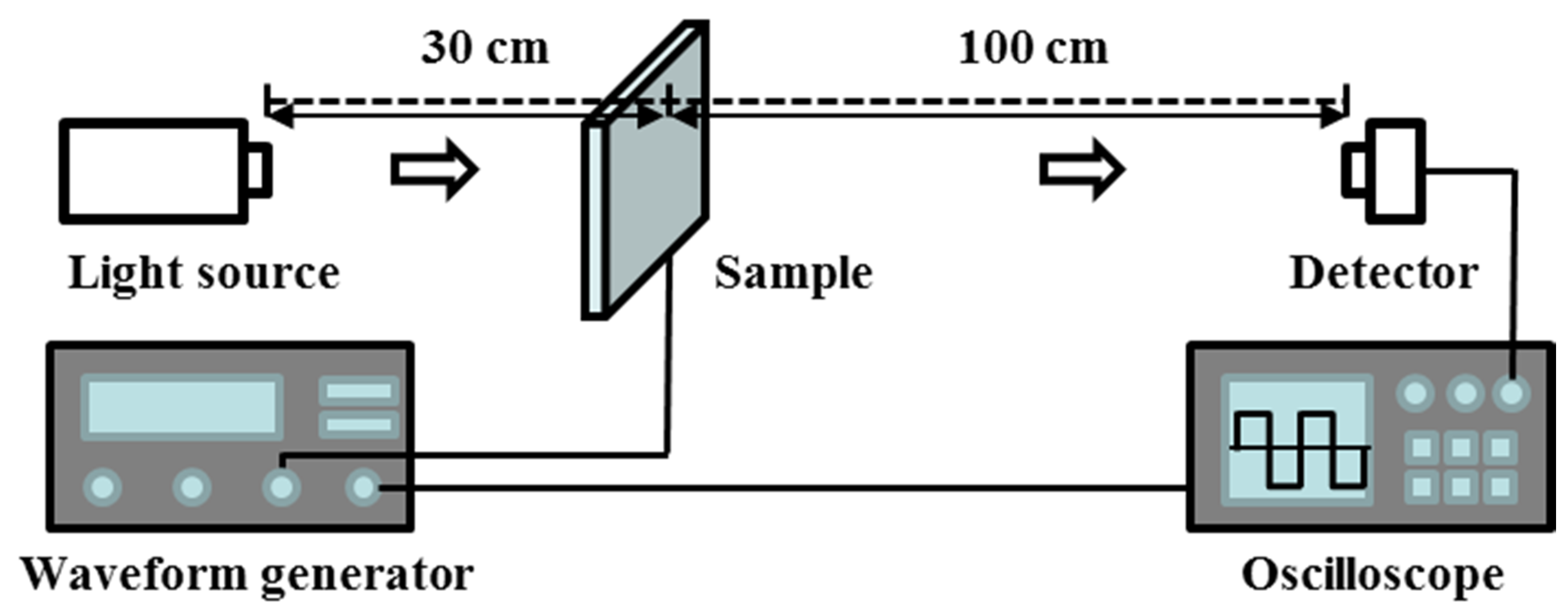
The transmittance properties with respect to the applied voltage of the device are measured. Figure 7 shows the schematic diagram of the measurement system. Using a waveform generator, voltages from 0 V to 110 V are applied and then the waveform and transmittance are observed simultaneously. A halogen lamp (Kwangwoo Co., Ltd., Korea) is used as the light source.
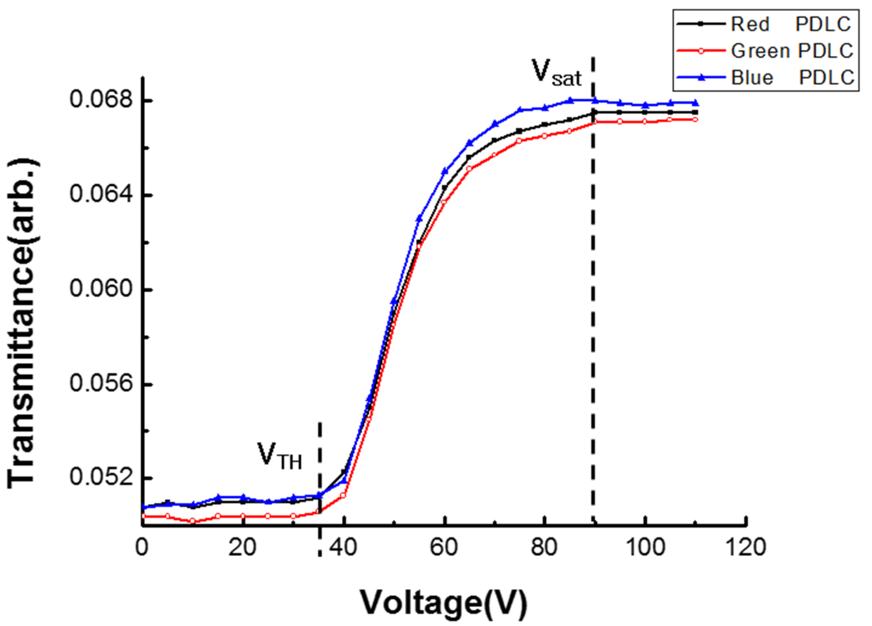
The lowest transmittance (TL) and highest transmittance (TH) are defined as the transmittance when the voltages are 0 V and 90 V, respectively. Figure 8 shows the measured voltage–transmittance curves. The transmittance of all the color PDLCs begins to change around 40 V, and the transmittance is saturated around 90 V. The driving voltage of PDLC can be further reduced by adding the nanoparticles [19].
4.2. Response Time
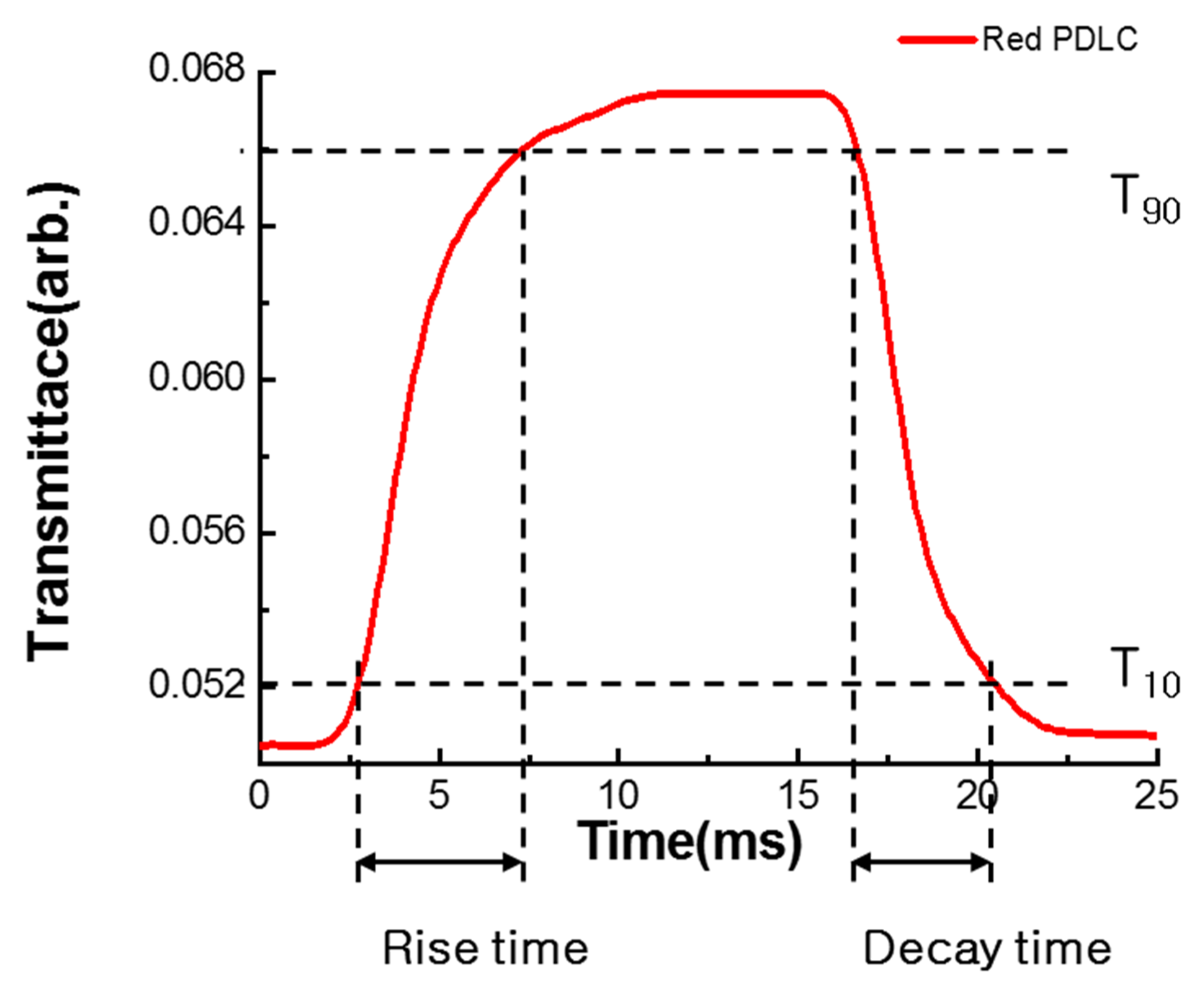
The switching property of PDLCs is related to the viscosity of the liquid crystals. When the viscosity of the liquid crystals increases, the switching time will increase as well. Fast switching can be achieved by adjusting the thickness of the device and the high-driving voltage [20]. The measured response time of the red PDLC device is shown in Figure 9. The switching time is measured by applying a voltage of 90 V at 1 kHz. The rise time and decay time of the red PDLCs are 4.6 ms and 3.7 ms, respectively. As a total, the switching time of the red PDLCs is 8.3 ms.
4.3. Tranmission Spectra
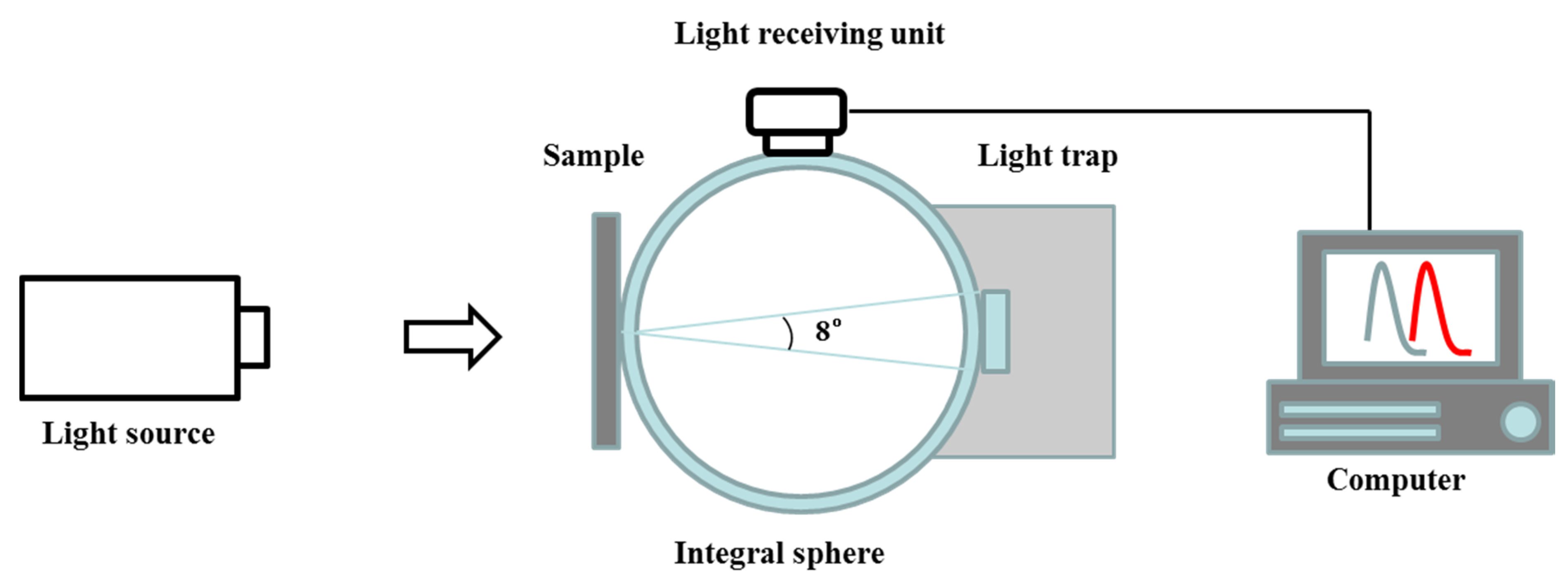
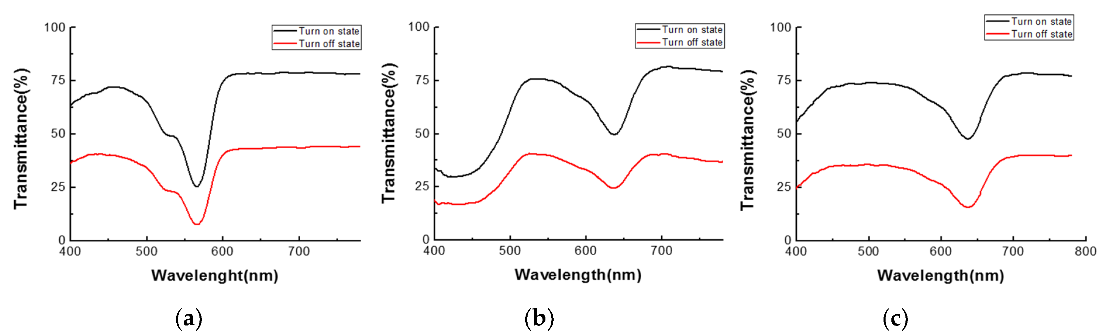
The transmittance with respect to the wavelength is measured using a haze meter (JCH-200S), as shown in Figure 10. The light from the light source first transmits through the sample, then is reflected in the integral sphere, and finally arrives at the light receiving unit. In the meantime, the transmission spectra are measured by the JCH-200S. Figure 11 shows the transmission spectra of the color PDLC device. For the red PDLCs, the transmittance is 75% when the voltage is applied. On the other hand, the transmittance is 38% when the voltage is removed. The results of the green and blue PDLCs are almost same as those of the red PDLCs.
4.4. Haze
Haze is measured by the haze meter (JCH-200S). After passing through the PDLC sample in the integrating sphere, light emitted by the halogen lamp is split into the scattered light and transmitted light. The inner surface of integrating sphere, which is uniformly coated with a highly reflective material, i.e. barium sulfate, can diffusively reflect the light towards the detector. The servomotor of the haze meter can rotate the wheel from the white plate to light trap to measure the scattered light and transmitted light, respectively. Then, the haze is calculated by:
where Ts is the scattered light and Tt is the transmitted light passing through the sample. Table 2 lists the results of the haze measurement. For the red PDLC device, the measured levels of haze are 16.89% and 65.21%, when the voltage is applied and removed, respectively. For the green and blue PDLC devices, the measured levels of haze are 15.82% and 18.55% in the turn-on state, while they are 67.32% and 70.76% in the turn-off state. Incidentally, the contrast ratio can be improved by incorporating other light modulation mechanisms, such as Kerr effect [21,22,23].
5. Conclusions
In this paper, a full color PDLC device with droplets adhering to a uniform size and shape has been demonstrated. Droplets of a fairly uniform size in large quantities can be obtained by means of membrane emulsification. With this method, liquid crystal droplets 4 µm in size are fabricated via membrane emulsification. Microcapsules are obtained by the complex coacervation with gelatin and gum arabic. By adding red, green, and blue pigments, color microcapsules are achieved. For the fabrication of PDLC devices, a mixture of 10 µm is coated on the bottom substrate using the bar coater. After drying the mixture, a UV adhesive is coated on the surface of the layer, and then the top substrate is attached to the bottom substrate to assemble the color PDLC device. Electro-optical properties of the fabricated color PDLC devices are evaluated. According to the experimental results, the saturation voltage of the device is 90 V, and the total switching time is 8.3 ms. In the turn-on state, the measured hazes of the red, green, blue PDLC devices are 16.89%, 15.82%, and 18.55%, respectively. In the turn-off state, the measured hazes of the devices are 65.21%, 67.32%, and 70.76%, respectively.
Author Contributions
Conceptualization, C.P.C. and C.G.J.; experiments: D.S.K.; writing—original draft preparation, D.S.K.; writing—review and editing, C.P.C. and C.G.J.; funding acquisition, C.P.C. and C.G.C.
Funding
This research is funded by the National Natural Science Foundation of China under Grant 61831015, the Science and Technology Commission of the Shanghai Municipality under Grant 19ZR1427200, and the Korea Institute for Advancement of Technology (KIAT) under Grant S2755592.
Conflicts of Interest
The authors declare no conflict of interest.
References
- Bunning, T.J.; Natarajan, L.V.; Tondiglia, V.P.; Sutherland, R.L. Holographic polymer-dispersed liquid crystals (H-PDLCs). Annu. Rev. Mater. Sci. 2000, 30, 83–115. [Google Scholar] [CrossRef]
- Jhun, C.G.; Chen, C.P.; Yoon, T.-H.; Kim, J.C. Multidomain structure for infinite memory time of bistable chiral splay nematic liquid crystal device. Jpn. J. Appl. Phys. 2006, 45, 5117–5120. [Google Scholar] [CrossRef]
- Chen, C.P.; Jhun, C.G.; Yoon, T.-H.; Kim, J.C. Viewing angle switching of tristate liquid crystal display. Jpn. J. Appl. Phys. 2007, 46, L676–L678. [Google Scholar] [CrossRef]
- Chen, C.P.; Lee, J.H.; Yoon, T.-H.; Kim, J.C. Monoview/dual-view switchable liquid crystal display. Opt. Lett. 2009, 34, 2222–2224. [Google Scholar] [CrossRef] [PubMed]
- Chen, C.P.; Wu, Y.; Zhou, L.; Wang, K.; Zhang, Z.; Jhun, C.G. Crosstalk-free dual-view liquid crystal display using patterned E-type polarizer. Appl. Opt. 2017, 56, 380–384. [Google Scholar] [CrossRef] [PubMed] [Green Version]
- Cupelli, D.; Nicoletta, F.P.; Manfredi, S.; Vivacqua, M.; Formoso, P.; De Filpo, G.; Chidichimo, G. Self-adjusting smart windows based on polymer-dispersed liquid crystals. Appl. Phys. Lett. 1999, 74, 3945–3947. [Google Scholar] [CrossRef]
- Nicoletta, F.P.; De Filpo, G.; Lanzo, J.; Chidichimo, G. A method to produce reverse-mode polymer-dispersed liquid-crystal shutters. Sol. Energy Mater. Sol. Cells 2009, 93, 2008–2012. [Google Scholar] [CrossRef]
- He, Z.-H.; Chen, C.P.; Zhu, J.L.; Yuan, Y.C.; Li, Y.; Hu, W.; Li, X.; Li, H.J.; Lu, J.G.; Su, Y.K. Electrically tunable holographic polymer templated blue phase liquid crystal grating. Chin. Phys. B 2015, 24, 064203. [Google Scholar] [CrossRef]
- Fergason, J.L. Encapsulated liquid crystal and method. U.S. Patent 4435047, 16 September 1981. [Google Scholar]
- West, J.L. Phase separation of liquid crystals in polymers. Mol. Cryst. Liq. Cryst. 1988, 157, 427–441. [Google Scholar] [CrossRef]
- Seki, H.; Uchida, T.; Shibata, Y. Dichroic dyes for guest-host liquid-crystal cells. Mol. Cryst. Liq. Cryst. 1986, 138, 349–365. [Google Scholar] [CrossRef]
- Kumar, P.; Neeraj; Kang, S.W.; Lee, S.H.; Raina, K.K. Analysis of dichroic dye-doped polymer-dispersed liquid crystal materials for display devices. Thin Solid Films 2011, 520, 457–463. [Google Scholar] [CrossRef]
- Vladisavljevic, G.T.; Schubert, H. Preparation and analysis of oil-in-water emulsions with a narrow droplet size distribution using Shirasu-porous-glass (SPG) membranes. Desalination 2002, 144, 167–172. [Google Scholar] [CrossRef]
- Yuyama, H.; Hashimoto, T.; Ma, G.H.; Nagai, M.; Omi, S. Mechanism of suspension polymerization of uniform monomer droplets prepared by glass membrane (Shirasu porous glass) emulsification technique. J. Appl. Polym. Sci. 2000, 78, 1025–1043. [Google Scholar] [CrossRef]
- Cosgrove, T. Colloid Science: Principles, Methods and Applications, 2nd ed.; Wiley: Chichester, West Sussex, UK, 2010. [Google Scholar]
- De Kruif, C.G.; Weinbreck, F.; de Vries, R. Complex coacervation of proteins and anionic polysaccharides. Curr. Opin. Colloid Interface Sci. 2004, 9, 340–349. [Google Scholar] [CrossRef]
- Kim, D.S.; Yeo, D.B.; Heo, K.C.; Gwag, J.S.; Jhun, C.G. Color polymer dispersed liquid crystal device with colored core-shell structure. Mol. Cryst. Liq. Cryst. 2015, 613, 39–44. [Google Scholar] [CrossRef]
- Chen, C.P.; Kim, K.H.; Yoon, T.H.; Kim, J.C. A viewing angle switching panel using guest–host liquid crystal. Jpn. J. Appl. Phys. 2009, 48, 062401. [Google Scholar] [CrossRef]
- Jamil, M.; Ahmad, F.; Rhee, J.T.; Jeon, Y.J. Nanoparticle-doped polymer-dispersed liquid crystal display. Curr. Sci. 2011, 101, 1544–1552. [Google Scholar]
- Bahadur, B. Liquid crystal displays. Mol. Cryst. Liq. Cryst. 1984, 109, 3–93. [Google Scholar] [CrossRef]
- Ge, Z.; Gauza, S.; Jiao, M.; Xianyu, H.; Wu, S.T. Electro-optics of polymer-stabilized blue phase liquid crystal displays. Appl. Phys. Lett. 2009, 94, 101104. [Google Scholar] [CrossRef] [Green Version]
- Rao, L.; Yan, J.; Wu, S.T.; Yamamoto, S.I.; Haseba, Y. A large Kerr constant polymer-stabilized blue phase liquid crystal. Appl. Phys. Lett. 2011, 98, 081109. [Google Scholar] [CrossRef] [Green Version]
- Chen, C.P.; Li, Y.; Su, Y.; He, G.; Lu, J.; Qian, L. Transmissive interferometric display with single-layer Fabry-Pérot filter. J. Disp. Technol. 2015, 11, 715–719. [Google Scholar] [CrossRef]
Figure 1.
Schematic diagram of membrane emulsification. The dispersed phase escapes through the porous membrane filter into the moving continuous phase. At the surface of the membrane filter, the dispersed droplets, which pass though the pore of the filter, will be detached by the shear stress in the continuous phase. In this way, droplet size can be effectively controlled by the shear stress.

Figure 2.
Fabricated liquid crystal droplets using a membrane filter with a pore size of 1.1 µm. The pore size of the membrane filter and the stirring velocity are important parameters, by which the size of the droplet can be determined. The smaller liquid crystal droplets can be obtained when using a membrane filter with a small pore size and the fast stirring velocity.

Figure 3.
Preparation process of the core–shell structured liquid crystal microcapsule. First, a 5 wt% gelatin aqueous solution and a 5 wt% gum arabic aqueous solution are prepared for 1 h at 40 °C. After the dissolution of gelatin and gum arabic, the red, green, and blue pigments are mixed and then the dispersed liquid crystal droplets are added. To adjust the pH, acetic acid is added until pH 4.5 is reached, according to a pH meter. As time passes, the liquid crystal droplets form into a mass. Therefore, by adding deionized water after the adjusting pH, the concentration of the mixture decreases. For gelation of the mixture, the temperature is kept at 4 °C, and then glutaraldehyde is added and the temperature is maintained at 4 °C. The mixture is then stirred for 24 h. Then, the microcapsules obtained from the above process are rinsed.

Figure 4.
Fabrication process of the polymer-dispersed liquid crystals (PDLCs) device. Indium tin oxide (ITO)-deposited glass is used as the top and bottom substrates. To clean the substrate, de-ionized water, acetone, and isopropyl alcohol (IPA) are used. After the cleaning process, a coating of the mixture of the liquid crystal capsules and polyvinyl alcohol (PVA) solution is applied by a bar coater (Gist). Polyvinyl alcohol (PVA205, Curaray), which has a refractive index of 1.51, is used as the polymer binder. The coated layer is dried at room temperature. After drying of the PDLC layer, the top substrate is bonded to the bottom substrate using UV adhesive with a thickness of 1 µm. By curing the device with UV light, the PDLC device is fabricated.

Figure 5.
Switching behavior of our color PDLCs with a core–shell structure. (a) When no voltage is applied, the encapsulated liquid crystals with a color shell are dispersed in the polymer matrix. The liquid crystal molecules in the droplet assume a bipolar or radial configuration depending on the interaction characteristics, which causes the light scattering. (b) By contrast, when a voltage is applied, the liquid crystal molecules are oriented in parallel to the electric field. In this state, light is transmitted by minimizing the scattering as the ordinary refractive index of the liquid crystal and the refractive index of polymer are nearly identical.

Figure 6.
Electro-optical effects of our color PDLC device. The scattering states of (a) the red PDLC device, (b) green PDLC device, and (c) blue PDLC device without a voltage being applied. The transparent states of (d) the red PDLC device, (e) green PDLC device, and (f) blue PDLC device with a voltage being applied.

Figure 7.
Schematic diagram of the experimental setup for measuring the voltage–transmittance (V–T) curves and response time. Using a waveform generator, voltages from 0 V to 110 V are applied and then the waveform and transmittance are observed simultaneously. A halogen lamp is used as the light source.

Figure 8.
Measured V–T curves of the color PDLCs. The transmittance of all the color PDLCs begins to change around 40 V, and the transmittance is saturated around 90 V.
Figure 8.
Measured V–T curves of the color PDLCs. The transmittance of all the color PDLCs begins to change around 40 V, and the transmittance is saturated around 90 V.

Figure 9.
Measured response time of the red PDLCs. The switching time is measured by applying a voltage of 90 V at 1 kHz. The rise time and decay time of the red PDLCs are 4.6 ms and 3.7 ms, respectively. As a total, the switching time of the red PDLCs is 8.3 ms.
Figure 9.
Measured response time of the red PDLCs. The switching time is measured by applying a voltage of 90 V at 1 kHz. The rise time and decay time of the red PDLCs are 4.6 ms and 3.7 ms, respectively. As a total, the switching time of the red PDLCs is 8.3 ms.

Figure 10.
Schematic diagram of the haze meter. The light from the light source first transmits through the sample, then is reflected in the integral sphere, and finally arrives at the light receiving unit.
Figure 10.
Schematic diagram of the haze meter. The light from the light source first transmits through the sample, then is reflected in the integral sphere, and finally arrives at the light receiving unit.

Figure 11.
Transmission spectra of transmitted light in the on and off states of (a) red, (b) green, and (c) blue PDLC devices, respectively.
Figure 11.
Transmission spectra of transmitted light in the on and off states of (a) red, (b) green, and (c) blue PDLC devices, respectively.


Table 1.
Properties of the liquid crystal (BHR71200-100).
| Properties | Value | |
|---|---|---|
| Clearing Point | 99 °C | |
| Flow Viscosity | 20 mm2s−1 | |
| Refractive anisotropy | ne | 1.705 |
| no | 1.506 | |
| Δn | 0.199 | |
| Dielectric anisotropy | ε∥ | 27.9 |
| ε⊥ | 6.6 | |
| Δε | 21.3 | |
Table 2.
Measured hazes of the color PDLC devices.
| Red PDLC | Green PDLC | Blue PDLC | |
|---|---|---|---|
| Haze (turn-on state) | 16.89% | 15.82% | 18.55% |
| Haze (turn-off state) | 65.21% | 67.32% | 70.76% |
© 2019 by the authors. Licensee MDPI, Basel, Switzerland. This article is an open access article distributed under the terms and conditions of the Creative Commons Attribution (CC BY) license (http://creativecommons.org/licenses/by/4.0/).
Share and Cite
MDPI and ACS Style
Chen, C.P.; Kim, D.S.; Jhun, C.G. Electro-Optical Effects of a Color Polymer-Dispersed Liquid Crystal Device by Micro-Encapsulation with a Pigment-Doped Shell. Crystals 2019, 9, 364. https://0-doi-org.brum.beds.ac.uk/10.3390/cryst9070364
AMA Style
Chen CP, Kim DS, Jhun CG. Electro-Optical Effects of a Color Polymer-Dispersed Liquid Crystal Device by Micro-Encapsulation with a Pigment-Doped Shell. Crystals. 2019; 9(7):364. https://0-doi-org.brum.beds.ac.uk/10.3390/cryst9070364
Chicago/Turabian StyleChen, Chao Ping, Dae Soo Kim, and Chul Gyu Jhun. 2019. "Electro-Optical Effects of a Color Polymer-Dispersed Liquid Crystal Device by Micro-Encapsulation with a Pigment-Doped Shell" Crystals 9, no. 7: 364. https://0-doi-org.brum.beds.ac.uk/10.3390/cryst9070364
Note that from the first issue of 2016, this journal uses article numbers instead of page numbers. See further details here.